

Craftsman 486.24449 Owner's Manual
SF=AR8
OWNERS
MANUAL
Model No.
486.24449
CAUTION:
Before usingthisproduct,
read thismanualand follow
all Safety Rules and
OperatingInstructions.
1
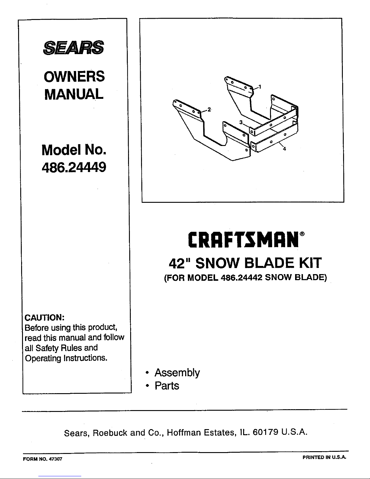
CRAFTSMANo
42" SNOW BLADE KIT
(FOR MODEL 486.24442 SNOW BLADE)
• Assembly
• Parts
Sears, Roebuck and Co., Hoffman Estates, IL. 60179 U.S.A.
FORM NO. 47307 PRINTED IN U.S_-
CARTON CONTENTS
1. LH. Frame Support Bracket
2. R.H. Frame Support Bracket
3, Upper Support Bracket
4. Lower Support Bracket
5. 1/4• x 3/4" Hex Bolt (2)
6. 1/4" LockWasher (2)
7. 1/4" Hex Nut (2)
24133 PiN
24134 P/N
24389 P/N
24388 PiN
43012 P/N
43177 P/N
43178 PiN
Use the following instructions in place of the instructions
for figures 1 through 5 in your blade owner's manual.
Use the 3/8 • bolts, nUtsand washers which are supplied
with your snow blade.
&
CAUTION: Do not begin assembling
until the tractor engine, muffler and
exhaust have been allowed to cool off.
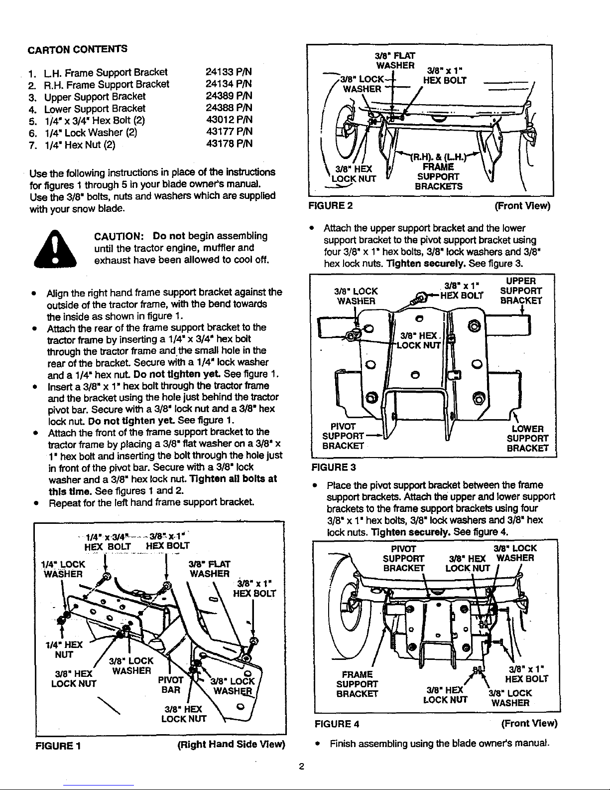
• Align the right hand frame support bracket against the
outside ofthe tractor frame, with the bend towards
the inside as shown in figure 1.
• Attach the rear of the frame support bracket to the
tractor frame by inserting a 1/4" x 3/4" hex bolt
through the tractor frame andthe small hole in the
rear of the bracket. Secure with a 1/4' lock washer
and a 1/4" hex nut. Do not tighten yet. See figure 1.
• Insert a 3/8" x 1• hex bolt through the tractor frame
and the bracket usingthe hole just behind the tractor
pivot bar. Secure with a 3/8" locknut and a 3/8" hex
lock nut. Do not tighten yet. See figure 1.
• Attach the front ofthe/tame support bracket to the
tractor frame by placing a 3/8•fiat washer ona 3/8" x
1' hex bolt and inserting the boltthrough the hole just
in front ofthe pivot bar. Secure with a 3/8" lock
washer and a 3/8" hex lock nut. Tighten all bolts at
this time. See figures 1 and 2.
• Repeat for the left hand frame support bracket.
• 1/4" X-3/4_...... 3/8"-X.-1_'
HE]( BOLT HE]( BOLT
1/4" LOCK | 3/8" FLAT
wA_;HER _ WASHER
3/8"x t"
HE](BOLT
1/4" HEX
NUT
3/8" HE](
LOCK NUT
\
PIVOT
BAR
3/8" HEX
LOCK NUT
FIGURE 1 (Right Hand Side Vie,/,
I 3/8" FLAT
--_. WASHER 3/8"x 1"
/3/8" LOCK--_ HEX BOLT _
/ WASHER 1---'- / _/
f .. .
[ --LOCKNUT w _urr'urtJ _j
L BRACKETS \
FIGURE 2 (Front View
Attach the upper supportbracket and the lower
supportbracket tothe pivot support bracket using
four3/8' x 1" hex bolts, 3/8" lock washers and 3/8'
hex lock nuts.Tighten securely. See figure 3.
3/8" x 1" UPPER
3/8" LOCK SUPPORT
WASHER BRACKET
PIVOT
SU
BRACKET
O
LOWER
SUPPORT
BRACKET
FIGURE 3
Place the pivot supportbracket between the frame
supportbrackets. Attach the upper and lower support
brackets to the frame support brackets using four
3/8" x 1• hex bolts, 3/8" lockwashers and 3/8" hex
lock nuts. Tighten securely. See figure 4.
PIVOT 3/8" LOCK
SUPPORT 3/8" HEX WASHER
BRACKET LOCKNUT
3/8" X 1"
FRAME HEX BOLT
SUPPORT
BRACKET 3/8" HEX 3/8" LOCK
LOCK NUT WASHER
FIGURE 4 (Front View
• Finish assembling usingthe blade owner's manual.
2
 Loading...