

Craftsman 486.24443 Owner's Manual
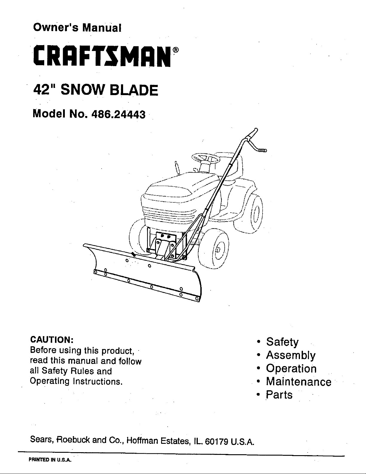
Owner's Manual
CRRFTSMRN
42" SNOW BLADE
Model No, 486.24443
CAUTION:
Before using this product,
read this manual and follow
all Safety Rules and
Operating Instructions.
• Safety
• Assembly
• Operation
• Maintenance
• Parts
Sears, Roebuck and Co., Hoffman Estates, IL. 60179 U.S.A.
PRINTED IN U.S.A.
SAFETY'RULES .......................................................... 2
ACCESSORIES ........................................................... 3
FULL SIZE HARDWARE CHART. ................................ 3
CARTON CONTENTS ................................................. 4
ASSEMBLY .............................................................. 5-9
OPERATION ........................................................ 10-11
MAINTENANCE ......................................................... 11
SERVICE AND ADJUSTMENTS ................................ 12
STORAGE ................................................................. 12
TROUBLESHOOTING ............................................... 13
REPAIR PARTS ILLUSTRATION ............................. 14
REPAIR PARTS LIST ................................................ 15
PARTS ORDERING/SERVICE ............... BACK COVER
LIMITED ONEYEAR WARRANTY ON 42" SNOW BLADE
Foroneyear from the date of purchase, when this snow blade is maintained and lubricated according to the operating and
maintenance instructions in the owneCs manual, Sears will repair any defect in material or workmanship free of charge.
Ifthissnow blade is usedfor commeroial or rentalpurposes,thiswarranty applies for only 90 days fromthe date of purchase.
Thiswarranty does not cover repairs necessary because ofoperator negligence or abuse, includingthe failure to maintain
the equipment according to instructionscontained in the owner's manual.
WARRANTY SERVICE IS AVAILABLE BY CONTACTING THE NEAREST SEARS SERVICE CENTER/DEPARTMENT
IN THE UNITED STATES.
This warranty applies only while this product is in the United States.
This warraintygives you specific legal rights, and you may also have other rights which vary from state to state.
Sears, Roebuck and Co. D/817 WA. Hoffman Estates, Chicago, IL 60179
Any power equipment can cause injury if operated improperly or if the user does not understand how to operate
the equipment. Exercise caution at all times, when using power equipment.
1. Read the tractor and snow blade owner's manuals
and know how to operate your tractor before using
tractor with snow blade attachment.
2. Never operate tractor and snow blade without wearing
properclothing suited to weather conditions and
operation of controls.
3. Never allow children to operate tractor and snow
blade, and do notallow adults to operate without
proper instructions.
4. Always begin with transmission infirst (low) gear and
gradually increase speed as required.
Look for this symbol to point out important safety precautions. It mean--Attention!! I
I
Become alert!! Your safety, Is Involved,
I
The model number and serial numbers will be found on a
decal attached to the snow blade.
You should record both the serial number and the date of
purchase and keep in a safe place for future reference.
MODELNUMBER.
SERIALNUMBER:
DATE OFPURCHASE:
486.24443
2"
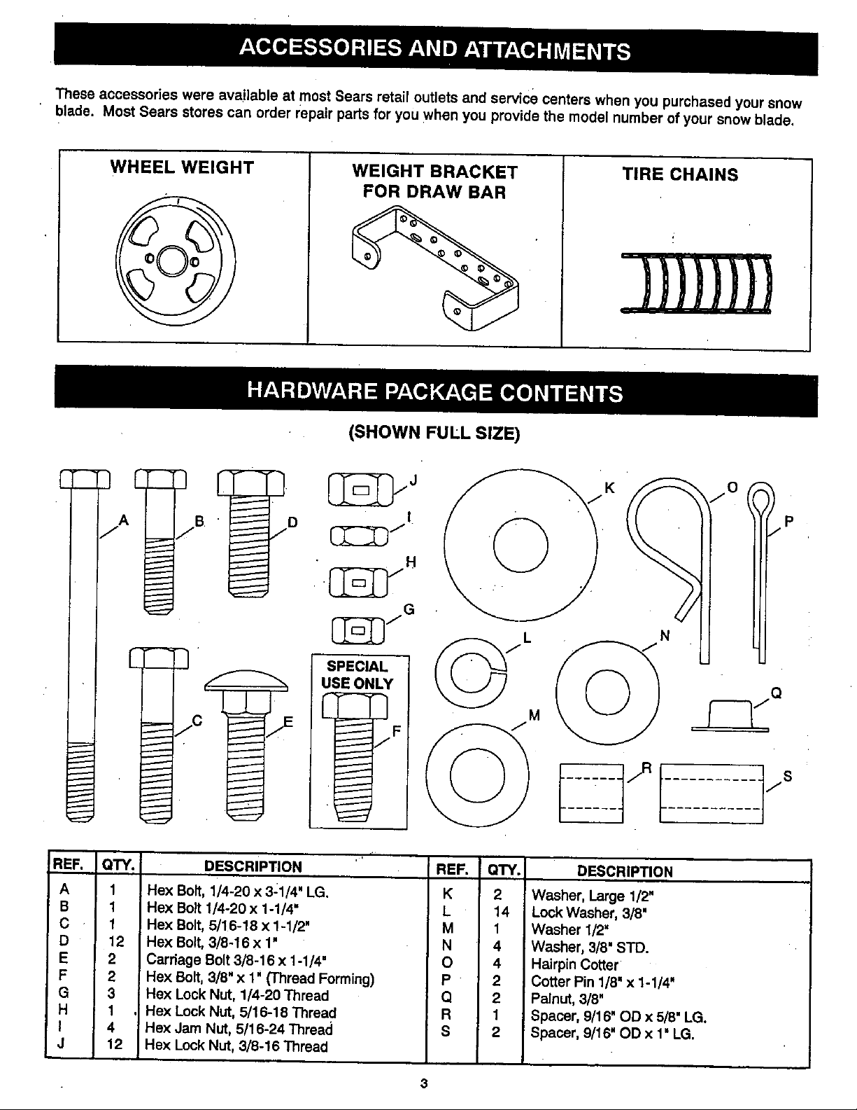
These accessories were available at most Sears retail outlets and service centers when you purchased your snow
blade Most Sears stores can order repair parts for you when you provide the model number of your snow blade
WHEEL WEIGHT WEIGHT BRACKET
FOR DRAW BAR
(SHOWN FUlL SIZE)
TIRE CHAINS
Aj
REF.
A
B
C
D
E
F
G
H
I
J
QTY. DESCRIPTION
q
1 Hex Bolt, 1/4-20 x 31/4' LG
1 Hex Bolt 1/4-20 x 1-1/4"
1 Hex Bolt, 5/16-18 x 1-1/2'
12 Hex Bolt, 3/8-16 x 1'
2 Carriage Bolt 3/8-16 x 1-1/4'
2 Hex Bolt, 3/8" x 1' (Thread Forming)
3 Hex Lock Nut, 1/4-20 Thread
1 Hex Lock Nut, 5/16-16 Thread
4 Hex Jam NUt, 6/16-24 Thread
12 Hex Lock NUt, 3/8-16 Thread
REF. QTY. DESCRIPTION
K 2 Washer, Large 1/2"
L 14 Lock Washer, 3/8'
M 1 Washer 1/2"
N 4 Washer, 3/8' STD.
O 4 Hairpin Cotter
P 2 Cotter Pin 1/8' x 1-1/4'
Q 2 Palnut, 3/8'
R 1 Spacer, 9/16' OD x 5/8" LG.
S 2 Spacer, 9/16" OD x 1' LG.
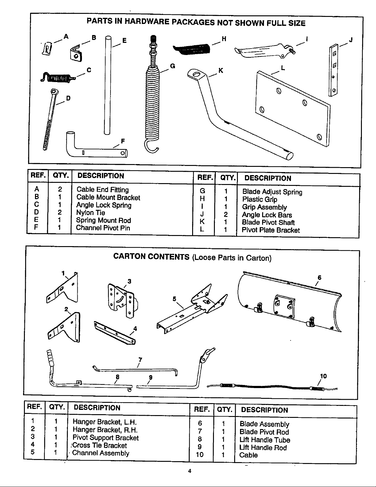
PARTS IN HARDWARE PACKAGES NOT SHOWN FULL SIZE
fA B H I
G
o 0
REF. I QTY. DESCRIPTION REF. QTY. DESCRIPTION
A 2
B 1
C 1
D 2
E 1
F 1
Cable End Fitting
Cable Mount Bracket
Angle Lock Spring
Nylon Tie
Spring Mount Rod
Channel Pivot Pin
G
H
I
J
K
L
1 Blade Adjust Spring
1 Plastic Grip
1 Grip Assembly
2 Angle Lock Bars
1 Blade Pivot Shaft
1 Pivot Plate Bracket
J
J
CARTON CONTENTS (Loose Parts in Carton)
2
3
l 7
e 9 0
_ / /
• u,
6
lO
/
REF. I QTY.
1 1
2 1
3 1
4 1
5 1
DESCRIPTION
Hanger Bracket, L.H.
Hanger Bracket, R.H.
Pivot Support Bracket
;Cross Tie Bracket
, Channel Assembly
REF. QTY.
6 1
7 1
8 1
9 1
10 1
DESCRIPTION
Blade Assembly
Blade Pivot Rod
Lift Handle Tube
Uft Handle Rod
Cable
4
TOOLS REQUIRED FOR ASSEMBLY
(I)
(i)
(i)
Pliers
Hemmer
Adjustable Wrench (or socket set)
9/16" Open End or Box End Wrench
7/16" Open End or Box End Wrench
1/2" Open End or Box End Wrench
• REMOVAL OF PARTS FROM CARTON
• Remove the loose parts and the hardware packages
from the carton. Lay out all parts and hardware and
identify using the illustrations on pages 3 and 4.
NOTE: Right hand (R.H.) and left hand (LH.) are deter-
mined from the operators position while seated
on the tractor.
&
CAUTION: Do not begin assembling
until the tractor engine, muffler and
exhaust deflector have been allowed
to cool off.
TRACTOR PREPARATION
• Allow engine, muffler and exhaust deflector to cool
before beginning.
• Refer to tractor owners manual to remove mower
deck or any other attachment you may have mounted
to your tractor. Mark all loose parts and save for
re-assembly.
• Refer to tractor owner's manual to remove tractor
hood for easier assembly of blade to tractor frame.
IF YOUR TRACTOR HAS FRONT SUSPENSION
BRACKETS LIKE FIGURE 1
• Remove two bolts from each side of the tractor
frame as shown in figure 1.
NOTE: Bolts should be assembled back into the holes
if the hanger brackets (figure 2) are removed from
the tractor frame.
REMOVE BOLTS FROM THESE HOLES
FIGURE 1
FRONT
SUSPENSION
BRACKET
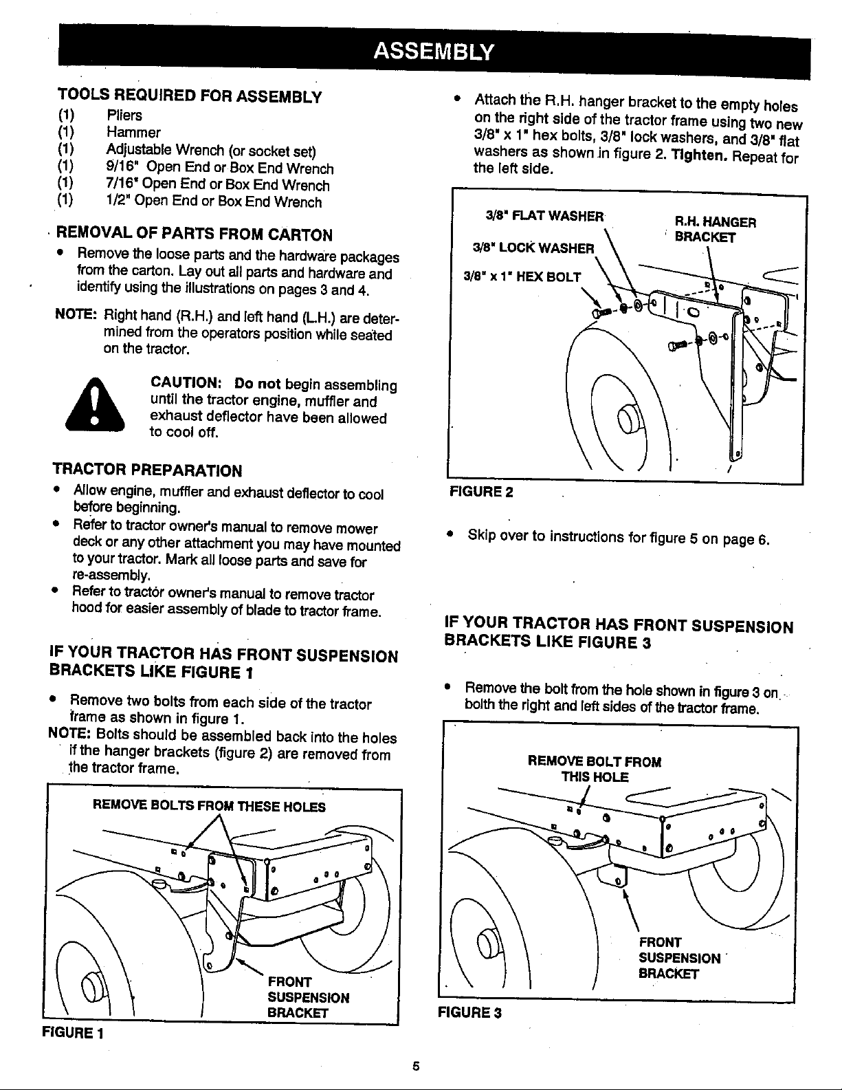
,, Attach the R.H. hanger bracket to the empty holes
on the right side of the tractor frame using two new
3/8' x 1" hex bolts, 3/8" lock washers, and 3/8" flat
washers as shown in figure 2. Tighten. Repeat for
the left side.
3/8" FLAT WASHER R,H. HANGER
3/8" LoCK WASHER \ ' BRACKET
!
FIGURE2
• Skip over to instructions for figure 5 on page 6.
IF YOUR TRACTOR HAS FRONT SUSPENSION
BRACKETS LIKE FIGURE 3
• Remove the bolt from the hole shown in figure 3 on
bolth the right and left sides ofthe tractor frame.
FIGURES
THIS HOLE
 Loading...