

Page 1
OPERATOR'S MANUAL
10 In. TABLE SAW
Model No.
315.284620
WARNING: To reduce the risk of injury, the
user must read and understand the operator’s
manuai before using this product.
Customer Help Line: 1-800-932-3188
Product distributed in the United States by Sears Brands Management Corporation
Hoffman Estates, IL 60179
Visit the Craftsman web page: www.craftsman.com
987000-910
4-23-10 (REV:03)
Save this manual for future reference
US
Page 2

TABLE OF CONTENTS
Warranty............................................................................................................................................................................2
Introduction.......................................................................................................................................................................2
General Safety Rules.....................................................................................................................................................3-4
Specific Safety Rules.....................................................................................................................................................4-5
Symbols.........................................................................................................................................................................6-7
Electrical........................................................................................................................................................................... 8
Glossary of Terms.............................................................................................................................................................9
Features.....................................................................................................................................................................10-13
Tools Needed..................................................................................................................................................................13
Loose Parts.....................................................................................................................................................................14
Assembly...................................................................................................................................................................15-21
Operation...................................................................................................................................................................22-35
Adjustments...............................................................................................................................................................36-38
Maintenance...................................................................................................................................................................38
Accessories.....................................................................................................................................................................39
Troubleshooting.........................................................................................................................................................39-40
Illustrated Parts List...................................................................................................................................................41-50
Parts Ordering/Service.......................................................................................................................................Back Page
WARRANT
CRAFTSMAN ONE YEAR FULL WARRANTY
FOR ONE YEAR from the date of purchase, this product is warranted against any defects in material or workmanship.
Defective product will receive free repair or free replacement if repair is unavailable.
For warranty coverage details to obtain repair or replacement, visit the web site: www.craftsman.com
This warranty does not cover the blade, which is an expendable part that can wear out from normal use within the war
ranty period.
This warranty is void if this product is ever used while providing commercial services or if rented to another person.
This warranty gives you specific legal rights, and you may also have other rights which vary from state to state.
Sears Brands Management Corporation, Hoffman Estates, IL 60179
INTRODUCTIO
I
J
j
This tool has many features for making its use more pleasant and enjoyable. Safety, performance, and dependability
have been given top priority in the design of this product making it easy to maintain and operate.
Page 3

GENERAL SAFETY RULES
j
Mm WARNING: Read and understand all instruc
tions. Failure to follow all instructions listed below,
may result in electric shock, fire and/or serious
personal injury.
READ ALL INSTRUCTIONS
■ KNOW YOUR POWER TOOL. Read the operator’s
manual carefully. Learn the saw’s applications and
limitations as well as the specific potential hazards
related to this tool.
■ GUARD AGAINST ELECTRICAL SHOCK BY PRE
VENTING BODY CONTACT WITH GROUNDED
SURFACES. For example, pipes, radiators, ranges,
refrigerator enclosures.
■ KEEP GUARDS IN PLACE and in good working order.
■ REMOVE ADJUSTING KEYS AND WRENCHES.
Form habit of checking to see that keys and adjusting
wrenches are removed from tool before turning it on.
■ KEEP WORK AREA CLEAN. Cluttered areas and
benches invite accidents. DO NOT leave tools or
pieces of wood on the saw while it is in operation.
■ DO NOT USE IN DANGEROUS ENVIRONMENTS.
Do not use power tools in damp or wet locations or
expose to rain. Keep the work area well lit.
■ KEEP CHILDREN AND VISITORS AWAY. All visitors
should wear safety glasses and be kept a safe
distance from work area. Do not let visitors contact
tool or extension cord while operating.
■ MAKE WORKSHOP CHILDPROOF with padlocks and
master switches, or by removing starter keys.
■ DON’T FORCE TOOL. It will do the job better and
safer at the feed rate for which it was designed.
■ USE RIGHT TOOL. Don’t force the tool or attachment
to do a job it was not designed for. Don’t use it for a
purpose not intended.
■ USE THE PROPER EXTENSION CORD. Make sure
your extension cord is in good condition. Use only a
cord heavy enough to carry the current your product
will draw. An undersized cord will cause a drop in line
voltage resulting in loss of power and overheating. A
wire gauge size (A.W.G.) of at least 14 is recommended
for an extension cord 25 feet or less in length. If in
doubt, use the next heavier gauge. The smaller the
gauge number, the heavier the cord.
■ DRESS PROPERLY. Do not wear loose clothing,
gloves, neckties, or jewelry. They can get caught
and draw you into moving parts. Rubber gloves and
nonskid footwear are recommended when working
outdoors. Also wear protective hair covering to contain
long hair.
■ ALWAYS WEAR SAFETY GLASSES WITH SIDE
SHIELDS. Everyday eyeglasses have only impact-
resistant lenses, they are NOT safety glasses.
SECURE WORK. Use clamps or a vise to hold work
when practical. It’s safer than using your hand and
frees both hands to operate tool.
DON’T OVERREACH. Keep proper footing and
balance at all times.
MAINTAIN TOOLS WITH CARE. Keep tools sharp
and clean for better and safer performance. Follow
instructions for lubricating and changing accessories.
DISCONNECT TOOLS. When not in use, before
servicing, or when changing attachments, blades, bits,
cutters, etc., all tools should be disconnected.
AVOID ACCIDENTAL STARTING. Be sure switch is off
when plugging in any tool.
USE RECOMMENDED ACCESSORIES. Consult the
operator’s manual for recommended accessories. The
use of improper accessories may risk injury.
NEVER STAND ON TOOL. Serious injury could occur
if the tool is tipped or if the cutting tool is unintention
ally contacted.
CHECK DAMAGED PARTS. Before further use of
the tool, a guard or other part that is damaged should
be carefully checked to determine that it will operate
properly and perform its intended function. Check for
alignment of moving parts, binding of moving parts,
breakage of parts, mounting and any other conditions
that may affect its operation. A guard or other part that
is damaged must be properly repaired or replaced by
an authorized service center to avoid risk of personal
injury.
USE THE RIGHT DIRECTION OF FEED. Feed work
into a blade or cutter against the direction of rotation of
blade or cutter only.
NEVER LEAVE TOOL RUNNING UNATTENDED.
TURN THE POWER OFF. Don’t leave tool until it
comes to a complete stop.
PROTECT YOUR LUNGS. Wear a face or dust mask if
the cutting operation is dusty.
PROTECT YOUR HEARING. Wear hearing protection
during extended periods of operation.
DO NOT ABUSE CORD. Never yank cord to discon
nect from receptacle. Keep cord from heat, oil, and
sharp edges.
WHEN OPERATING A POWER TOOL OUTSIDE, USE
AN OUTDOOR EXTENSION CORD MARKED “W-A”
OR “W”. These cords are rated for outdoor use and
reduce the risk of electric shock.
KEEP BLADES CLEAN, SHARP, AND WITH
SUFFICIENT SET. Sharp blades minimize stalling
and kickback.
KEEP HANDS AWAY FROM CUTTING AREA. Keep
hands away from blades. Do not reach underneath
work or around or over the blade while blade is
rotating. Do not attempt to remove cut material when
blade is moving.
Page 4

GENERAL SAFETY RULES
J
BLADE COASTS AFTER BEING TURNED OFF. NEVER USE IN AN EXPLOSIVE ATMOSPHERE.
Normal sparking of the motor could ignite fumes.
INSPECT TOOL CORDS PERIODICALLY. If damaged,
have repaired by a qualified service technician at
an authorized service facility. The conductor with
insulation having an outer surface that is green with
or without yellow stripes is the equipment-ground
ing conductor. If repair or replacement of the electric
cord or plug is necessary, do not connect the equip
ment-grounding conductor to a live terminal. Repair
or replace a damaged or worn cord immediately. Stay
constantly aware of cord location and keep it well away
from the rotating blade.
INSPECT EXTENSION CORDS PERIODICALLY and
replace if damaged.
GROUND ALL TOOLS. If tool is equipped with three-
prong plug, it should be plugged into a three-hole
electrical receptacle.
CHECK WITH A QUALIFIED ELECTRICIAN or service
personnel if the grounding instructions are not com
pletely understood or if in doubt as to whether the tool
is properly grounded.
USE ONLY CORRECT ELECTRICAL DEVICES: 3-wire
extension cords that have 3-prong grounding plugs and
3-pole receptacles that accept the tool’s plug.
DO NOT MODIFY the plug provided. If it will not fit the
outlet, have the proper outlet installed by a qualified
electrician.
KEEP TOOL DRY, CLEAN, AND FREE FROM OIL
AND GREASE. Always use a clean cloth when clean
ing. Never use brake fluids, gasoline, petroleum-based
products, or any solvents to clean tool.
STAY ALERT AND EXERCISE CONTROL. Watch
what you are doing and use common sense. Do not
operate tool when you are tired. Do not rush,
DO NOT USE TOOL IF SWITCH DOES NOT TURN IT
ON AND OFF. Have defective switches replaced by an
authorized service center,
USE ONLY CORRECT BLADES. Do not use blades
with incorrect size holes. Never use blade washers or
blade bolts that are defective or incorrect. The maxi
mum blade capacity of your saw is 10 in. (254 mm).
BEFORE MAKING A CUT, BE SURE ALL ADJUST
MENTS ARE SECURE.
BE SURE BLADE PATH IS FREE OF NAILS. Inspect
for and remove all nails from lumber before cutting,
NEVER TOUCH BLADE or other moving parts during
use.
NEVER START A TOOL WHEN ANY ROTATING COM
PONENT IS IN CONTACT WITH THE WORKPIECE.
DO NOT OPERATE A TOOL WHILE UNDER THE
INFLUENCE OF DRUGS, ALCOHOL, OR ANY
MEDICATION.
WHEN SERVICING use only identical replacement
parts. Use of any other parts may create a hazard or
cause product damage.
USE ONLY RECOMMENDED ACCESSORIES listed
in this manual or addendums. Use of accessories
that are not listed may cause the risk of personal
injury. Instructions for safe use of accessories are
included with the accessory,
DOUBLE CHECK ALL SETUPS. Make sure blade is
tight and not making contact with saw or workpiece
before connecting to power supply.
SPECIFIC SAFETY RULES
FIRMLY BOLT THE SAW TO A WORK BENCH OR
LEG STAND at approximately hip height,
NEVER OPERATE THE SAW ON THE FLOOR.
GUARD AGAINST KICKBACK. Kickback occurs
when the blade stalls rapidly and workpiece is driven
back towards the operator. It can pull your hand into
the blade resulting in serious personal injury. Stay out
of blade path and turn switch off immediately if blade
binds or stalls.
USE RIP FENCE. Always use a fence or straight edge
guide when ripping,
SUPPORT LARGE PANELS. To minimize risk of blade
pinching and kickback, always support large panels.
REMOVE ALL FENCES AND AUXILIARY TABLES
before transporting saw. Failure to do so can result in
an accident causing possible serious personal injury.
j
ALWAYS USE BLADE GUARD, SPREADER, AND
ANTI-KICKBACK PAWLS on all “through-sawing”
operations. Through-sawing operations are those in
which the blade cuts completely through the workpiece
as in ripping or cross cutting. Keep the blade guard
down, the anti-kickback pawls down, and the spreader
in place.
ALWAYS SECURE WORK firmly against the rip fence
or miter gauge. NEVER use the rip fence during the
same operation as the miter gauge.
WHEN MAKING NON-THROUGH RIP CUTS, always
use a push stick, push block, and/or featherboard so
your hands do not come within 3 inches of the saw
blade.
WHEN RIPPING NARROW STOCK, always use a
push stick, push block, or featherboard.
Page 5

SPECIFIC SAFETY RULES
j
NEVER perform any operation “freehand” which
means using oniy your hands to support or guide the
workpiece. Aiways use either the rip fence or miter
gauge to position and guide the work.
NEVER stand or have any part of your body in iine
with the path of the saw blade.
NEVER reach behind, over, or within three inches of
the blade or cutter with either hand for any reason.
MOVE THE RIP FENCE out of the way when cross
cutting.
NEVER use rip fence as cutoff gauge when cross
cutting.
NEVER attempt to free a stalled saw blade without
first turning the saw OFF and disconnecting the saw
from the power source.
PROVIDE ADEQUATE SUPPORT to the rear and
sides of the saw table for wide or long workpieces.
AVOID KICKBACKS (work thrown back toward you)
by:
a) Keeping blade sharp.
b) Keeping rip fence parallel to the saw blade.
c) Keeping spreader, anti-kickback pawls, and
blade guard in place and operating.
d) Not releasing the work before it is pushed all the
way past the saw blade using a push stick.
e) Not ripping work that is twisted or warped or
does not have a straight edge to guide along
the fence.
IF THE POWER SUPPLY CORD IS DAMAGED, it
must be replaced only by the manufacturer or by an
authorized service center to avoid risk.
AVOID AWKWARD OPERATIONS AND HAND
POSITIONS where a sudden slip could cause your
hand to move into the cutting tool.
USE ONLY RECOMMENDED ACCESSORIES listed in
this manual or addendums. Use of accessories that are
not listed may cause the risk of personal injury. Instruc
tions for safe use of accessories are included with the
accessory.
MAKE SURE THE WORK AREA HAS AMPLE LIGHT
ING to see the work and that no obstructions will inter
fere with safe operation BEFORE performing any work
using the table saw.
ALWAYS TURN OFF SAW before disconnecting it, to
avoid accidental starting when reconnecting to power
supply.
HOLD THE WORKPIECE FIRMLY AGAINST THE
TABLE.
THIS TOOL should have the following markings:
a) Wear eye protection.
b) Use saw blade guard and riving knife/spreader/
splitter for every operation for which it can be
used, including all through sawing.
c) Keep hands out of the line of saw blade.
d) Use a push stick when required.
e) Pay particular attention to instructions on reducing
risk of kickback.
f) Do not perform any operation freehand.
g) Never reach around or over the saw blade.
h) Never operate saw on floor or below waist height.
SAVE THESE INSTRUCTIONS. Refer to them
frequently and use to instruct other users. If you loan
someone this tool, loan them these instructions also.
Page 6

SYMBOLS
Some of the following symbols may be used on this tool. Please study them and learn their meaning. Proper inter
pretation of these symbols will allow you to operate the tool better and safer.
1
A
Safety Alert
Read Operator’s Manual
©
0
Eye Protection
No Hands Symbol
Wet Conditions Alert Do not expose to rain or use in damp locations.
€)
V
A
Hz Hertz
W Watt Power
Volts Voltage
Amperes
Indicates a potential personal injury hazard.
To reduce the risk of injury, user must read and understand
operator’s manual before using this product.
Always wear eye protection with side shields marked to
comply with ANSI Z87.1,
Failure to keep your hands away from the blade will result
in serious personal injury.
Current
Frequency (cycles per second)
min
srs
no
0
,,,/min
Minutes Time
Alternating Current
Direct Current
No Load Speed Rotational speed, at no load
Class II Construction
Per Minute Revolutions, strokes, surface speed, orbits etc., per minute
Type of current
Type or a characteristic of current
Double-insulated construction
Page 7

SYMBOLS
The following signal words and meanings are intended to explain the levels of risk associated with this product.
1
SYMBOL SIGNAL
A
A
A
SERVICE
Servicing requires extreme care and knowiedge and
shouid be performed oniy by a quaiified service tech
nician, For service we suggest you return the product to
your nearest AUTHORIZED SERVICE CENTER for repair.
When servicing, use oniy identicai repiacement parts.
WARNING:
DANGER:
WARNING:
CAUTION:
CAUTION:
MEANING
Indicates an imminently hazardous situation, which, if not avoided, will
result in death or serious injury.
Indicates a potentially hazardous situation, which, if not avoided, could
result in death or serious injury.
Indicates a potentially hazardous situation, which, if not avoided, may
result in minor or moderate injury.
(Without Safety Alert Symbol) Indicates a situation that may result in
property damage.
WARNING: To avoid serious personal injury, do not
attempt to use this product until you read thoroughly
and understand completely the operator’s manual.
Save this operator’s manual and review frequently for
continuing safe operation and instructing others who
may use this product.
The operation of any power tool can result in foreign objects being thrown into your eyes, which can
result in severe eye damage. Before beginning power tool operation, always wear safety goggles or
safety glasses with side shields and a full face shield when needed. We recommend Wide Vision Safety
Mask for use over eyeglasses or standard safety glasses with side shields. Always use eye protection
which is marked to comply with ANSI Z87.1,
SAVE THESE INSTRUCTIONS
Page 8
ELECTRICAL
EXTENSION CORDS
Use only 3-wire extension cords that have 3-prong
grounding plugs and 3-pole receptacles that accept the
tool’s plug. When using a power tool at a considerable
distance from the power source, use an extension cord
heavy enough to carry the current that the tool will draw.
An undersized extension cord will cause a drop in line
voltage, resulting in a loss of power and causing the
motor to overheat. Use the chart provided below to
determine the minimum wire size required in an extension
cord. Only round jacketed cords listed by Underwriter’s
Laboratories (UL) should be used.
**Ampere rating (on tool data plate)
0-2.0 2.1-3.4
Cord Length
25' 16 16 16 16
50' 16 16 16
100' 16 16
"Used on 12 gauge- 20 amp circuit.
NOTE: AWG = American Wire Gauge
3.5-5.0 5.1-7.0 7.1-12.0 12.1-16.0
Wire Size (A.W.G.)
14 14
14 14 12
14 12
10 -
When working with the tool outdoors, use an extension
cord that is designed for outside use. This is indicated by
the letters “WA” on the cord’s jacket.
Before using an extension cord, inspect it for loose or
exposed wires and cut or worn insulation,
A WARNING: Keep the extension cord clear of the
working area. Position the cord so that it will not get
caught on lumber, tools or other obstructions while
you are working with a power tool. Failure to do so
can result in serious personal injury.
A WARNING: Check extension cords before each
use. If damaged replace immediately. Never use tool
with a damaged cord since touching the damaged
area could cause electrical shock resulting in serious
injury,
SPEED AND WIRING
The no-load speed of this tool is approximately 5,000 rpm.
This speed is not constant and decreases under a load or
with lower voltage. For voltage, the wiring in a shop is as
important as the motor’s horsepower rating, A line intend
ed only for lights cannot properly carry a power tool motor.
Wire that is heavy enough for a short distance will be too
light for a greater distance. A line that can support one
power tool may not be able to support two or three tools.
GROUNDING INSTRUCTIONS
This product must be grounded. In the event of a malfunc
tion or breakdown, grounding provides a path of least
resistance for electric current to reduce the risk of electric
shock. This tool is equipped with an electric cord having
an equipment-grounding
conductor and a grounding plug. The plug must be
plugged into a matching outlet that is properly installed
and grounded in accordance with all local codes and ordi
nances.
Do not modify the plug provided. If it will not fit the outlet,
have the proper outlet installed by a qualified electrician.
Ak WARNING: Improper installation of the ground
ing plug can result in a risk of electric shock. When
repair or replacement of the cord is required, do
not connect the grounding wire to either flat blade
terminal. The wire with insulation having an outer
surface that is green with or without yellow stripes is
the grounding wire.
Check with a qualified electrician or service personnel if
the grounding instructions are not completely understood,
or if in doubt as to whether the tool is properly grounded.
Repair or replace a damaged or worn cord immediately.
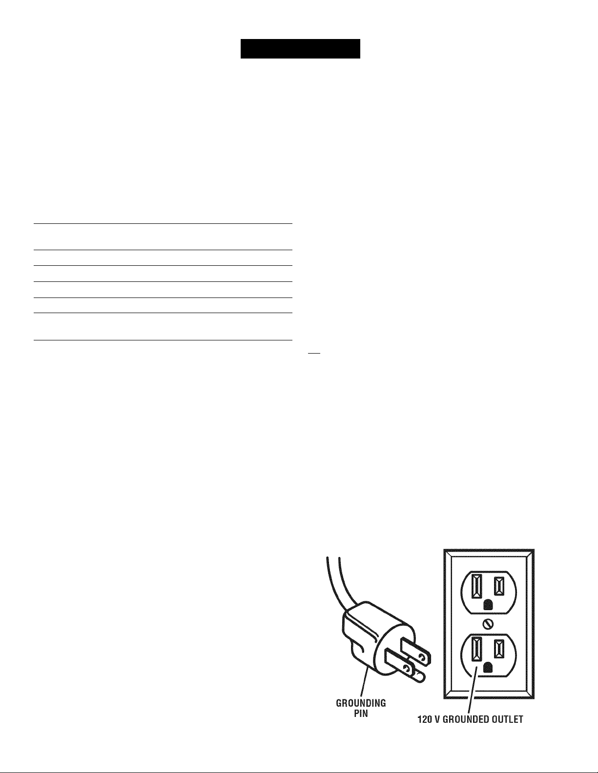
This product is for use on a nominal 120 volt circuit and
has a grounding plug similar to the plug illustrated in fig
ure 1, Only connect the product to an outlet having the
same configuration as the plug. Do not use an adapter
with this product.
ELECTRICAL CONNECTION
This tool is powered by a precision built electric motor.
It should be connected to a power supply that is 120
volts, AC only (normal household current), 60 Hz. Do
not operate this tool on direct current (DC). A substantial
voltage drop will cause a loss of power and the motor will
overheat. If the saw does not operate when plugged into
an outlet, double check the power supply.
Fig. 1
Page 9

GLOSSARY OF TERM
J
Anti-Kickback Pawls (radial arm and table saws)
A device which, when properiy instaiied and maintained,
is designed to stop the workpiece from being kicked back
toward the front of the saw during a ripping operation.
Arbor
The shaft on which a biade or cutting tooi is mounted.
Bevel Cut
A cutting operation made with the biade at any angie
other than 90° to the tabie surface.
Compound Cut
A cross cut made with both a miter and a bevei angie.
Cross Cut
A cutting or shaping operation made across the grain or
the width of the workpiece.
Cutterhead (planers and jointer planers)
A rotating cutterhead with adjustabie blades or knives.
The blades or knives remove material from the workpiece.
Dado Cut
A non-through cut which produces a square-sided notch
or trough in the workpiece (requires a special blade).
Featherboard
A device used to help control the workpiece by holding it
securely against the table or fence during any ripping
operation.
FPM or SPM
Feet per minute (or strokes per minute), used in reference
to blade movement.
Freehand
Performing a cut without the workpiece being guided by a
fence, miter gauge, or other aids.
Gum
A sticky, sap-based residue from wood products.
Heel
Alignment of the blade to the fence.
Kerf
The material removed by the blade in a through cut or the
slot produced by the blade in a non-through or partial cut.
Kickback
A hazard that can occur when the blade binds or stalls,
throwing the workpiece back toward operator.
Miter Cut
A cutting operation made with the workpiece at any angle
to the blade other than 90°.
Non-Through Cuts
Any cutting operation where the blade does not extend
completely through the thickness of the workpiece.
Pilot Hole (drill presses)
A small hole drilled in a workpiece that serves as a guide
for drilling large holes accurately.
Push Blocks (for jointer planers)
Device used to feed the workpiece over the jointer planer
cutterhead during any operation. This aid helps keep the
operator’s hands well away from the cutterhead.
Push Blocks (for table saws)
Device used to hold the workpiece during cutting opera
tions. This aid helps keep the operator’s hands well away
from the blade.
Push Sticks (for table saws)
Device used to push the workpiece during cutting opera
tions. A push stick should be used for narrow ripping
operations. The aid helps keep the operator’s hands well
away from the blade.
Resaw
A cutting operation to reduce the thickness of the
workpiece to make thinner pieces.
Resin
A sticky, sap-based substance that has hardened.
Revolutions Per Minute (RPM)
The number of turns completed by a spinning object in
one minute.
Ripping or Rip Cut
A cutting operation along the length of the workpiece.
Riving Knife/Spreader/SpIitter (table saws)
A metal piece, slightly thinner than the blade, which helps
keep the kerf open and also helps to prevent kickback.
Saw Blade Path
The area over, under, behind, or in front of the blade. As
it applies to the workpiece, that area which will be or has
been cut by the blade.
Set
The distance that the tip of the saw blade tooth is bent (or
set) outward from the face of the blade.
Snipe (planers)
Depression made at either end of a workpiece by cutter
blades when the workpiece is not properly supported.
Through Sawing
Any cutting operation where the blade extends completely
through the thickness of the workpiece.
Throw-Back
The throwing back of a workpiece usually caused by the
workpiece being dropped into the blade or being placed
inadvertently in contact with the blade.
Workpiece or Material
The item on which the operation is being done.
Worktable
Surface where the workpiece rests while performing a
cutting, drilling, planing, or sanding operation.
Page 10
FEATURES
PRODUCT SPECIFICATIONS
Blade Arbor...............................................................5/8 in.
Blade Diameter.........................................................10 in.
Blade Tilt..................................................................0° - 45°
Rating
...............................................
120 V, AC only, 60 Hz
Input
.....................................................................
No Load Speed
....................................
5,000 r/min, (RPM)
15 Amps
Cutting Depth at 0°...............................................3-1/2 in.
Cutting Depth at 45°.............................................2-1/2 in.
ANTI-KICKBACK
PAWLS
OUTFEED
SUPPORT
BLADE
WRENCH
STORAGE
BLADE
SPREADER/ GUARD
RIVING KNIFE
RIP
FENCE
SLIDING TABLE
EXTENSION
SCALE
FRONT
RAIL
10
BEVEL
INDICATOR
Fig, 2
Page 11

FEATURES
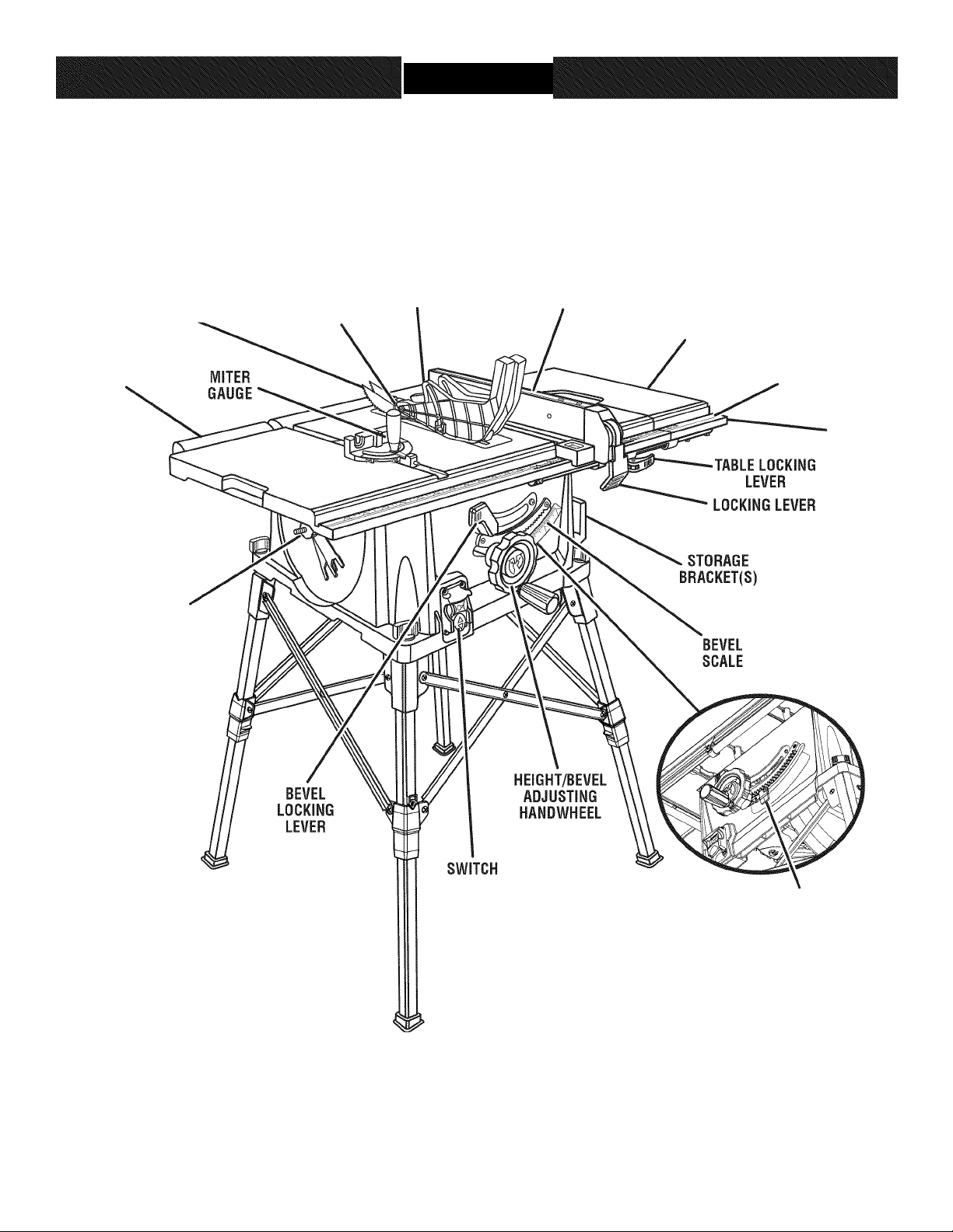
KNOW YOUR TABLE SAW
See Figure 2.
The safe use of this product requires an understanding of
the information on the tool and in this operator’s manual
as well as a knowledge of the project you are attempt
ing, Before use of this product, familiarize yourself with all
operating features and safety rules.
ANTI-KICKBACK PAWLS - Kickback is a hazard in which
the workpiece is thrown back toward the operator. The
teeth on the anti-kickback pawls point away from the
workpiece. If the workpiece should be pulled back toward
the operator, the teeth dig into the wood to help prevent
or reduce the possibility of kickback,
BEVEL SCALE - The easy-to-read scale on the front of
the cabinet shows the exact blade angle.
BLADE - This saw is provided with a 36-tooth, 10 in,
carbide blade. The blade is raised and lowered with
the height/bevel adjusting handwheel. Bevel angles are
locked with the bevel locking lever,
Jk WARNING: Do not use blades rated less than the
speed of this tool. Failure to heed this warning could
result in personal injury,
BLADE GUARD - Always keep the blade guard down
over the saw blade for through-sawing cuts.
BEVEL LOCKING LEVER - This lever, placed just under
the saw table surface on the front of the cabinet, locks the
angle setting of the blade.
HEIGHT/BEVEL ADJUSTING HANDWHEEL - Located
on the front of the cabinet, use this handwheel to lower
and raise the blade for height adjustments or blade re
placement, This handwheel also makes the adjustment for
bevel angles easy.
MITER GAUGE - The miter gauge aligns the wood for
a cross cut. The easy-to-read indicator shows the exact
angle for a miter cut, with positive stops at 90° and 45°.
MITER GAUGE GROOVES - The miter gauge rides in the
grooves on the saw table.
OUTFEED SUPPORT - This table extension at the back
of the tool gives the operator additional support when cut
ting long workpieces.
RIP FENCE - A sturdy metal fence guides the workpiece
and is secured with the locking handle. Grooves run along
the top and sides of the rip fence for use with optional
clamps and accessories.
SCALE - Located on the front rail, the easy-to-read scale
provides precise measurements for rip cuts.
SLIDING TABLE EXTENSIONS - Located on each side
of the saw table, these table extension gives the operator
additional support when cutting wide workpieces.
SPREADER/RIVING KNIFE - A removable metal piece
of the blade guard assembly, slightly thinner than the saw
blade, which helps keep the kerf open and prevent kick
back. When in the through sawing, or “up” position, it is
higher than the saw blade and becomes a spreader. When
in the non-through sawing, or “down” position, it is below
the saw blade teeth and becomes a riving knife.
SWITCH ASSEMBLY - This saw has an easy access
power switch located below the front rail. To lock the
switch in the OFF position, remove the switch key from
the switch. Place the key in a location that is inaccessible
to children and others not qualified to use the tool.
11
Page 12
FEATURES
OPERATING COMPONENTS
The upper portion of the blade projects up through the
table and is surrounded by an insert called the throat
plate. The height of the blade is set with a handwheel on
the front of the cabinet. To accommodate wide panels,
the saw table has rails on each side. Detailed instructions
are provided in the Operation section of this manual for
the basic cuts: cross cuts, miter cuts, bevel cuts, and
compound cuts.
The rip fence is used to position work for lengthwise cuts.
A scale on the front rail shows the distance between the
rip fence and the blade.
It is very important to use the blade guard assembly for all
through-sawing operations. The blade guard assembly
includes: riving knife/spreader/splitter, anti-kickback
pawls, and plastic blade guard.
POWER SWITCH
This saw is equipped with a power switch that has a
built-in locking feature. This feature is intended to prevent
unauthorized and possible hazardous use by children and
others.
TO TURN YOUR SAW ON:
■ With the switch key inserted into the switch, lift the
switch button to turn ON {I),
TO TURN YOUR SAW OFF:
■ Press the switch button down to turn OFF { O),
TO LOCK YOUR SAW:
■ Press the switch button down,
■ Remove the switch key from the switch and store in a
safe, secure location.
WARNING: Always remove the switch key when
the tool is not in use and keep it in a safe place. In
the event of a power failure, turn the switch OFF
{ O) and remove the key. This action will prevent the
tool from accidentally starting when power returns.
WARNING: ALWAYS make sure your workpiece is
not in contact with the blade before operating the
switch to start the tool. Failure to heed this warning
may cause the workpiece to be kicked back toward
the operator and result in serious personal injury.
WARNING: To reduce the risk of accidental starting.
Always make sure the switch is in the OFF {O) position
before plugging tool into the power source.
SWITCH
ON
SWITCH
OFF
12
SWITCH KEY
SWITCH IN LOCKED POSITION
Fig. 3
Page 13
FEATURES
BLADES
For maximum performance, it is recommended that you
use the 36-tooth, 10 in. carbide-tipped combination biade
provided with your saw. Additional blade styles of the
same high quality are available for specific operations
such as ripping. Your local dealer can provide you with
complete information.
Kerf width must be within the limits stamped on the
spreader/riving knife.
A WARNING: Do not use blades rated less than the
speed of this tool. Failure to heed this warning could
result in personal injury.
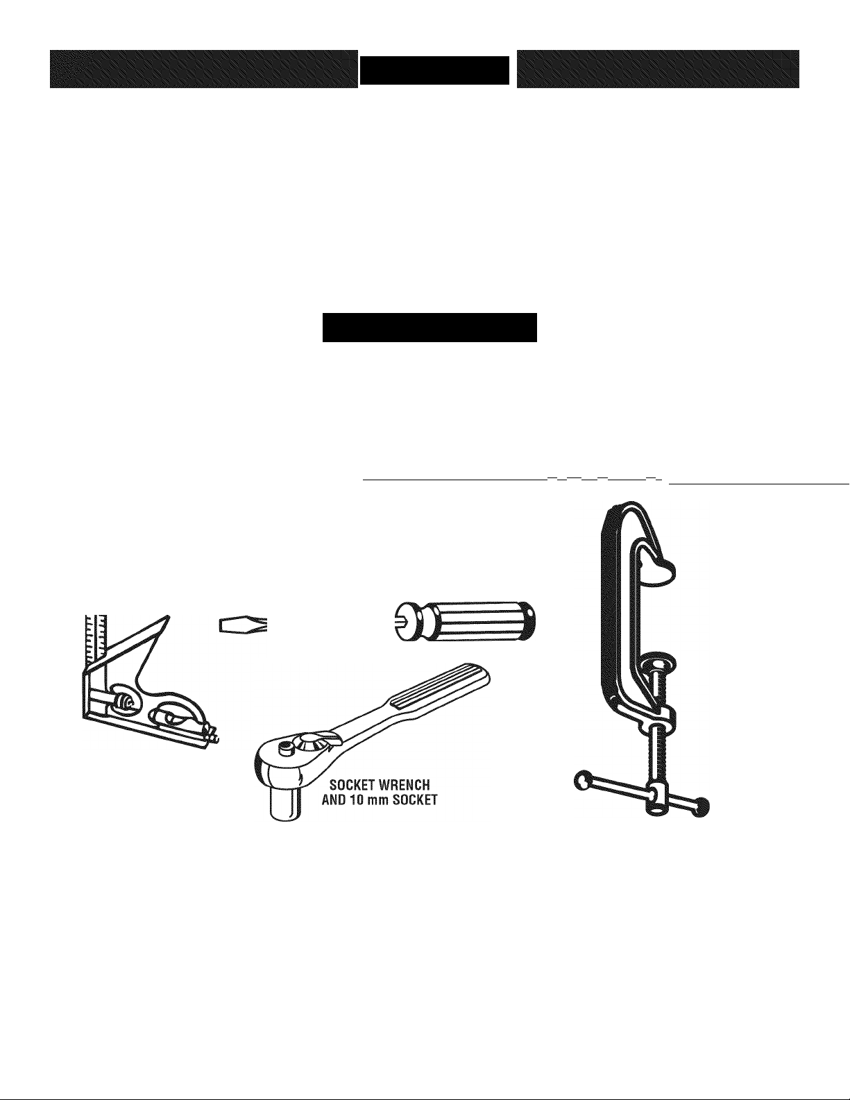
TOOLS NEEDED
The following tools (not included or drawn to scale) are needed for assembly and making adjustments:
rTTTTfrjTTT|TTT|TrTjfTTpTr^^
COMBINATION
SQUARE
11 I 1.1 I l-iJ.j.l-1-i IJ 1.1 lilt I I ■ 111 < I I I I I I 1
PHILLIPS
SCREWDRIVER
FLATHEAD
SCREWDRIVER
FRAMING SQUARE
......11......
C-CLAMPS
L 1 1 I 11 ■ I »I
13
Fig. 4
Page 14
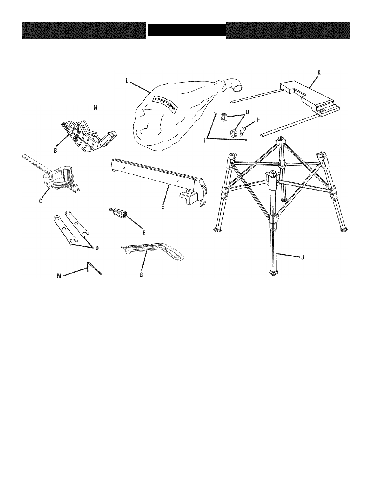
LOOSE PARTS
The following items are included with your table saw:
A, Anti-Kickback Pawls................................................1
B, Blade Guard...........................................................1
C, Miter Gauge...........................................................1
D, Blade Wrench.........................................................2
E, Handle Assembly...................................................1
F, Rip Fence
G, Push Stick..............................................................1
H, Indicator
..............................................................
.................................................................
Fig. 5
I, Screw
J, Leg Stand
K, Sliding Table Assembly
L, Dust Bag................................................................1
M, Hex Key (3 mm, 5 mm)...........................................2
1
1
N, Switch Key..............................................................1
O, End Plug.................................................................2
14
.....................................................................
..............................................................
.........................................
2
1
1
Page 15

ASSEMBL
UNPACKING
This product requires assembiy.
■ Carefully lift saw from the carton and place it on a level
work surface.
NOTE: This tool is heavy. To avoid back injury, keep
your knees bent and lift with your legs, not your back,
and get help when needed.
A WARNING: Do not use this product if any parts on
the Loose Parts List are already assembled to your
product when you unpack it. Parts on this list are not
assembled to the product by the manufacturer and
require customer installation. Use of a product that
may have been improperly assembled could result in
serious personal injury.
■ Inspect the tool carefully to make sure no breakage or
damage occurred during shipping.
■ Do not discard the packing material until you have
carefully inspected the tool, identified all loose parts,
and satisfactorily operated the tool.
NOTE: Remove the foam block from between the saw’s
housing and the motor by first beveling the blade (see
page 26).
■ The saw is factory set for accurate cutting. After
assembling it, check for accuracy. If shipping has
influenced the settings, refer to specific procedures
explained in this manual.
■ If any parts are damaged or missing, please call
1 -800-932-3188 for assistance.
A WARNING: If any parts are damaged or missing, do
not operate this tool until the parts are replaced. Use
of this product with damaged or missing parts could
result in serious personal injury.
At WARNING: Do not attempt to modify this tool
or create accessories not recommended for use
with this tool. Any such alteration or modification is
misuse and could result in a hazardous condition
leading to possible serious personal injury.
A WARNING: Do not connect to power suppiy until
assembly is compiete. Failure to comply could result
in accidental starting and possible serious personal
injury.
Mk WARNING: Do not lift the saw without help. Hold
it close to your body. Keep your knees bent and lift
with your legs, not your back. Ignoring these precau
tions can result in back injury,
WARNING: Never stand directly in line with the
blade or allow hands to come closer than 3 in, to the
biade. Do not reach over or across the blade. Failure
to heed this warning can result in serious personal
injury,
A WARNING: To avoid serious personal injury, always
make sure the table saw is securely mounted to a
workbench or an approved leg stand. NEVER oper
ate the saw on the floor,
MOUNTING HOLES
The table saw must be mounted to a firm supporting
surface such as a workbench or leg stand. If bolted to
a workbench, remove the four locking knobs. Four bolt
holes have been provided in the saw’s base for this pur
pose. Each of the four mounting holes should be bolted
securely using 3/8 in, machine bolts, lock washers, and
hex nuts (not included). Bolts should be of sufficient
length to accommodate the saw base, lock washers, hex
nuts, and the thickness of the workbench. Tighten all four
bolts securely.
Carefully check the workbench after mounting to make
sure that no movement can occur during use. If any tip
ping, sliding, or walking is noted, secure the workbench to
the floor before operating.
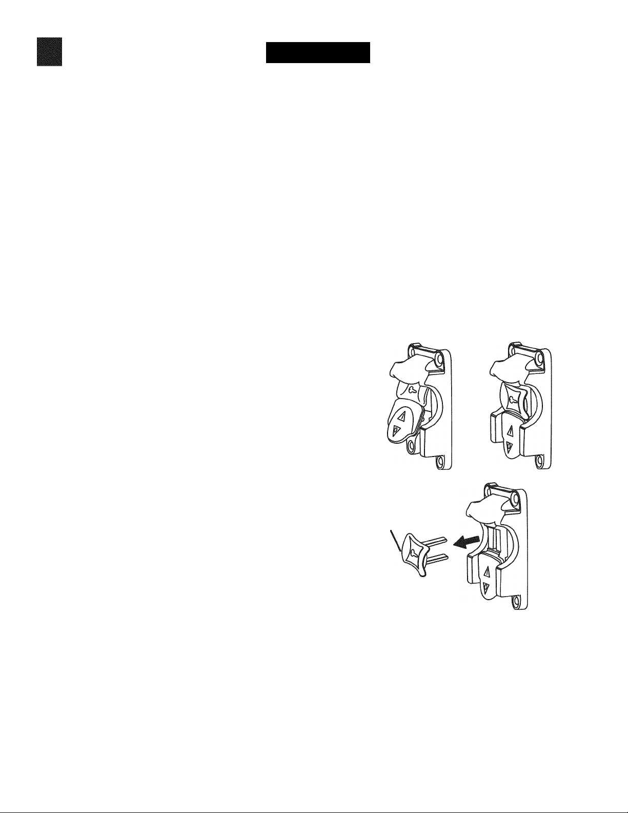
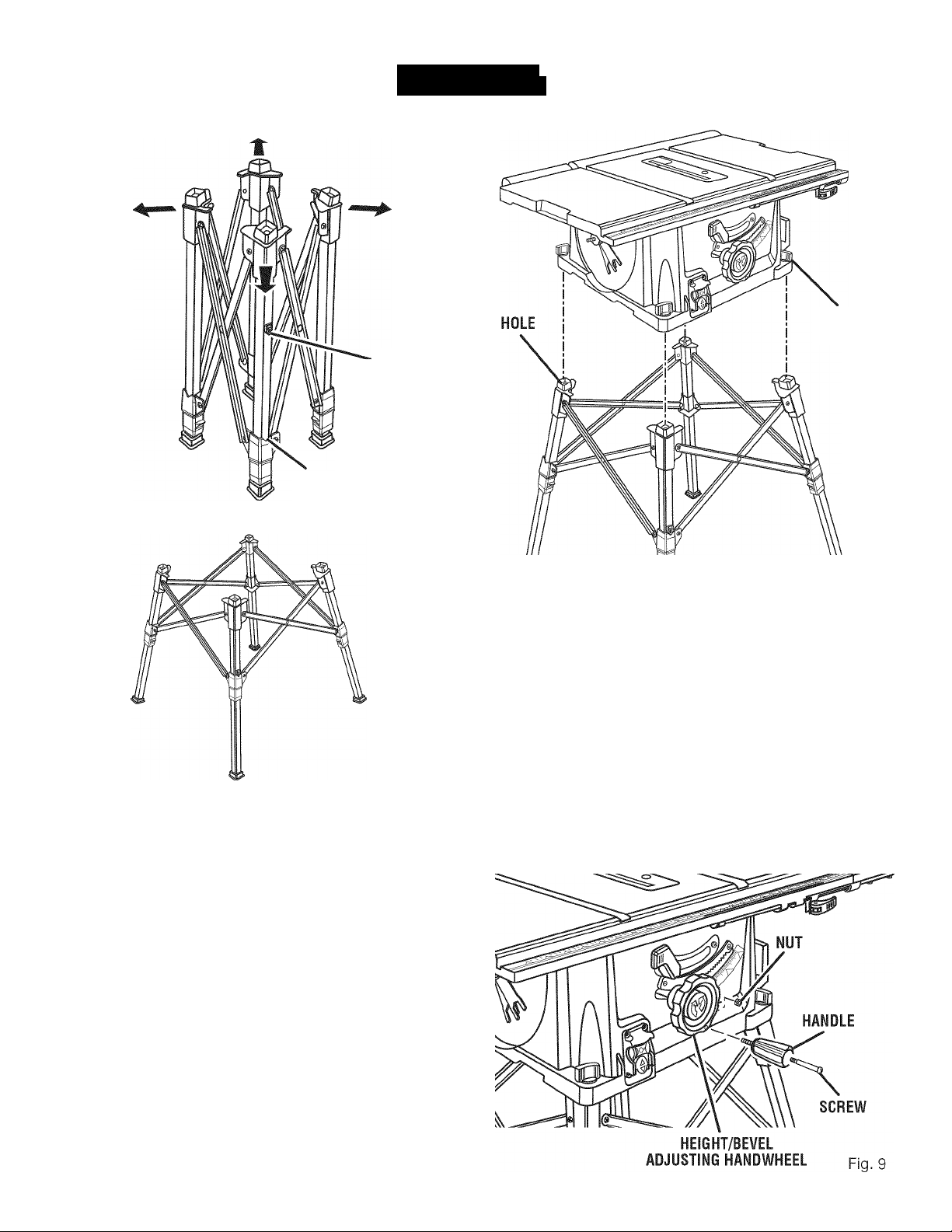
TO ASSEMBLE THE LEG STAND
See Figures 6 - 7.
NOTE: Do not use this leg stand with other equipment or
for other purposes.
■ Place the leg stand on the floor,
■ Keeping fingers and all body parts away from the
stand’s moving parts, open the leg stand by pushing
opposite legs in opposite directions as indicated by the
arrows in figure 6. The stand will be fully opened when
the red indicator rests in the V slot of the grip,
NOTE: Only mount the saw when the stand is
completely opened.
15
Page 16
VSLOT
ASSEMBL
RED
INDICATOR
Fig. 6
i
I
LOCKING
KNOB
Fig. 7
MOUNTING THE TABLE SAW BASE TO THE
LEG STAND
See Figure 8.
■ Place the table saw base on the leg stand. Position the
locking knob over the holes in the top of the leg stand.
■ Insert the screw on the locking knob into the hole and
turn the locking knob clockwise to secure the table saw
base to the leg stand.
■ Repeat with the other three locking knobs.
Fig. 8
TO INSTALL THE HANDLE
See Figure 9.
■ Hold the nylon nut securely and turn the screw
counter- clockwise to remove the nut completely.
NOTE: Do not remove the screw from the handle.
■ Place the nylon nut into the recessed hole on the back
of the height/bevel adjusting handwheel and hold in
place.
■ Slide the handle and screw into the hole on the
height/bevel adjusting handwheel.
■ Using a flathead screwdriver, turn the screw clockwise
and tighten in place.
16
Page 17

ASSEMBL
j
TO REMOVE/REPLACE THE THROAT PLATE
See Figure 10.
■ Lower the blade by turning the height/bevel adjusting
handwheel counterclockwise.
■ To remove the throat plate, place your index finger in
the hole and lift the front end pulling the throat plate
out toward the front of the saw,
■ To reinstall the throat plate, slip the tab into the slot at
the back of the saw and push down to secure in place.
To place in riving knife position (or “down” position for all
non-through cutting):
■ Remove the throat plate.
■ Raise the saw blade by turning the height/bevel adjust
ing handwheel clockwise.
■ Unlock the release lever by pulling it up.
■ Push the riving knife down until it is below the saw
blade.
■ Lock the release lever by pushing the lever down,
■ Reinstall the throat plate.
TO CHANGE BETWEEN A SPREADER AND A
RIVING KNIFE
See Figure 11.
This saw is shipped with the spreader/riving knife placed
in the non-through cutting or “down” position (riving knife
position).
NOTE: The spreader/riving knife must be placed in the
through cutting, or “up” position (spreader position), for all
other cutting operations.
■ Unplug the saw.
To place in spreader position (or “up” position for all
through cutting):
■ Remove the throat plate.
■ Raise the saw blade by turning the height/bevel adjust
ing handwheel clockwise.
■ Unlock the release lever by pulling it up.
■ Grasp the spreader and pull it towards the right side of
the saw to release the spreader from the spring-loaded
riving clamp,
■ Pull the spreader up until the internal pins are engaged
and the spreader is above the saw blade.
■ Lock the release lever by pushing the lever down,
■ Reinstall the throat plate.
RELEASE
IN “DOWN” POSITION FOR NON-THROUGH CUTTING
Fig. 11
17
Page 18

ASSEMBL
J
TO CHECK SAW BLADE INSTALLATION
See Figure 12.
CAUTION: To work properly, the saw blade teeth must
point down toward the front of the saw. Failure to do so
could cause damage to the saw blade, the saw, or the
workpiece.
■ Unplug the saw.
■ Lower the saw blade and remove the throat plate.
■ Make sure the bevel locking lever Is securely pushed to
the left, see Figure 14. Raise the saw blade to Its full
height by turning the helght/bevel adjusting handwheel
clockwise.
■ Place spreader/riving knife In “up” position.
To loosen the blade:
■ Remove the blade wrench from the blade wrench stor
age area.
■ Using blade wrenches, place the flat open end of a
blade wrench on the flats on the arbor shaft,
■ Insert the closed end of the blade wrench over the
blade nut. Holding both wrenches firmly, pull the
wrench (right side) forward to the front of the machine.
To tighten the blade:
■ Using the blade wrench, place the flat open end Into
the flats on the arbor shaft,
■ Insert the closed end of the blade wrench over the
blade nut. Holding both wrenches firmly, push the
wrench (right side) to the back of the machine. Make
sure the blade nut Is securely tightened. Do not over
tighten,
■ Reinstall the throat plate.
■ Check all clearances for free blade rotation.
TO INSTALL THE ANTI-KICKBACK PAWLS AND
BLADE GUARD
See Figures 13 - 15.
A. WARNING: Replace dull or damaged antl-kickback
pawls. Dull or damaged pawls may not stop a kick
back Increasing the risk of serious personal Injury,
Antl-kickback pawls should only be Installed for through
cuts.
■ Unplug the saw.
■ Raise the saw blade by turning the helght/bevel adjust
ing handwheel clockwise.
■ Place spreader/rIvIng knife In “up” position.
To install anti-kickback pawls:
■ Press and hold the button on the right side of the antlkickback pawls.
PAWL
HANDLE
BUTTON
BLADE
BLADE
GUARD
GUARD
LEVER
Fig. 14
18
Page 19

ASSEMBL
j
■ Align the slot in the pawls over the rear hole in the
spreader/hving knife.
■ Push the pawl handle down snapping them into place
and release the button.
NOTE: Pull on the pawl handle to make sure pawls are
securely locked.
To install blade guard:
■ Lift the guard lever up to unlock.
■ With the front of the blade guard raised, lower the
back of the guard into the middle hole of the spreader/
riving knife. Push the front of the guard down until it is
parallel to the table (see figure 15). If the blade guard
is not parallel to the table, the riving knife is not in the
spreader (or “up”) position.
■ Lock the guard in place by pushing the guard lever
down.
NOTE: Blade alignment with the spreader can be adjusted
for different blade widths. Refer to: To Check and Align the
Spreader/Riving Knife and Saw Blade. Check the blade
guard assembly for clearances and free movement.
■ The saw blade and spreader/riving knife are aligned
when the framing square contacts both the blade and
spreader/riving knife evenly with no gaps.
If the spreader/riving knife is out of alignment with the saw
blade, adjustment is needed. The spreader/riving knife
must be in alignment front to back (horizontally) and top to
bottom (vertically).
To adjust (horizontally):
■ Remove the anti-kickback pawls and blade guard
assembly.
■ Loosen the screws holding the mounting bracket.
■ Reposition the spreader/riving knife left or right as
needed to align the spreader/riving knife with the saw
blade.
■ Once properly aligned, securely retighten all screws.
To adjust (vertically):
■ Slowly turn the set screws until the riving knife is
aligned with the blade.
HORIZONTAL ADJUSTMENT
SOUARE
TO CHECK AND ALIGN THE SPREADER/RIVING
KNIFE AND SAW BLADE
See Figure 16.
To check alignment of the spreader/riving knife:
■ Unplug the saw.
■ Raise the saw blade by turning the height/bevel adjust
ing handwheel clockwise.
■ Remove the anti-kickback pawls and blade guard
assembly. Place a framing square or straight edge
against both the saw blade and the spreader.
NOTE: Place framing square between carbide teeth
and measure from blade. This step will insure framing
square is square against blade from the front to back of
blade.
FRAMING
SOUARE
19
Page 20

ASSEMBL
TO ASSEMBLE THE SLIDING TABLE
ASSEMLBY
See Figures 17 - 18.
To install sliding table extension:
■ Locate the sliding table assembly.
■ Unlock the front and back table locking levers.
■ Insert sliding table assembly Into table locking levers.
■ Push the table assembly until It rests against the saw
table and Is completely closed.
■ Install Phillips head screw Into hole at end of the rear
extension rod to hold sliding table assembly Into lock
ing levers.
■ Lock the front and back table locking levers.
To install indicator:
■ Locate the indicator.
■ Slip the indicator in the slot on the front rail. Fit the top
slot in the indicator over the detent on the end plug
and the bottom slot over the screw hole on the end
plug.
■ Insert a screw into the bottom slot of the indicator, the
hole in the end plug and the extension rod. Tighten se
curely, but do not overtighten. Overtighting may crush
extension rod ends.
I
j
Fig. 17
20
Page 21

ASSEMBL
TO INSTALL DUST BAG
See Figure 19.
■ Slide the elbow inside the dust chute on the back of
the table saw.
NOTE: For efficient operation, empty the dust bag before
it is half full. This will permit better air flow through the
bag.
J
BLADE
WRENCHES
Fig. 20
TO STORE THE TABLE SAW ACCESSORIES
See Figures 20 - 21.
The table saw has two convenient storage areas (one on
either side of the saw cabinet) specifically designed for
the saw’s accessories.
When not in use, store the accessories securely by snap
ping each accessory in place.
21
Page 22

OPERATIC
I
^ WARNING: Do not allow familiarity with tools
to make you careless. Remember that a careless
fraction of a second Is sufficient to Inflict severe
Injury,
WARNING: Always wear eye protection with side
shields marked to comply with ANSI Z87.1, Failure to
do so could result In objects being thrown Into your
eyes, resulting In possible serious Injury.
A WARNING: Do not use any attachments or
accessories not recommended by the manufacturer
of this tool. The use of attachments or accessories
not recommended can result In serious personal
Injury,
WARNING: Although many of the Illustrations In
this manual are shown with the blade guard removed
for clarity, do not operate the saw without the blade
guard unless specifically Instructed to do so.
APPLICATIONS
You may use this tool for the purposes listed below:
■ Straight line cutting operations such as cross cutting,
ripping, mitering, beveling, and compound cutting
■ Dado with optional accessories
■ Cabinet making and woodworking
NOTE: This table saw Is designed to cut wood and wood
composition products only.
BASIC OPERATION OF THE TABLE SAW
The 3-prong plug must be plugged Into a matching outlet
that Is properly Installed and grounded according to all
local codes and ordinances. Improper connection of the
equipment can result In electric shock. Do not modify
the plug If It will not fit the outlet. Have the correct outlet
Installed by a qualified electrician. Refer to the Electrical
section In this manual.
CAUSES OF KICKBACK
Kickback can occur when the blade stalls or binds, kick
ing the workpiece back toward you with great force and
speed. If your hands are near the saw blade, they may
be jerked loose from the workpiece and may contact the
blade. Kickback can cause serious Injury. Use precautions
to avoid the risks.
Kickback can be caused by any action that pinches the
blade In the wood such as:
■ Making a cut with Incorrect blade depth
■ Sawing Into knots or nails In the workpiece
■ Twisting the wood while making a cut
■ Falling to support work
■ Forcing a cut
■ Cutting warped or wet lumber
■ Using the wrong blade for the type of cut
■ Not following correct operating procedures
■ Misusing the saw
■ Falling to use the antl-kickback pawls
■ Cutting with a dull, gummed-up, or Improperly set
blade
AVOIDING KICKBACK
■ Always use the correct blade depth setting. The top of
the blade teeth should clear the workpiece by 1/8 In, to
1/4 In,
■ Inspect the work for knots or nails before beginning a
cut. Knock out any loose knots with a hammer. Never
saw Into a loose knot or nail.
■ Always use the rip fence when rip cutting. Use the
miter gauge when cross cutting. This helps prevent
twisting the wood In the cut,
■ Always use clean, sharp, and properly-set blades.
Never make cuts with dull blades.
■ To avoid pinching the blade, support the work properly
before beginning a cut,
■ When making a cut, use steady, even pressure. Never
force cuts.
■ Do not cut wet or warped lumber,
■ Use extra caution when cutting some prefinished or
composition wood products as the antl-kickback pawls
may not always be effective.
■ Always guide your workpiece with both hands or with
push sticks and/or push blocks. Keep your body In a
balanced position to be ready to resist kickback should
It occur. Never stand directly In line with the blade.
■ Use of a featherboard will help hold the workpiece
securely against the saw table or fence.
■ Clean the saw, blade guard, under the throat plate, and
any areas where saw dust or scrap workpieces may
gather.
■ Use the right type of blade for the cut being made.
■ Always use the spreader / riving knife for every
operation where It Is allowed. The use of this device
will greatly reduce the risk of kickback.
22
Page 23

OPERATION
CUTTING AIDS
See Figure 22.
Push sticks are devices that may be used for pushing a
workpiece through the blade in any rip cut. When mak
ing non-through cuts or ripping narrow stock, always use
a push stick, push block, and/or featherboard so your
hands do not come within 3 inches of the saw blade.
They can be made in various sizes and shapes from scrap
wood and used in a specific project. The stick must be
narrower than the workpiece, with a 90° notch in one end
and shaping for a grip on the other end.
A push block has a handle fastened by recessed screws
from the underside. Use push blocks for narrow cuts and
all non-through cuts.
CAUTION: Be sure the screws in a push block are
recessed to avoid damaging the saw or workpiece.
PUSH BLOCKS
Fig. 22
AUXILIARY FENCE
An auxiliary fence is a device used to close the gap be
tween the rip fence and the saw table. Always make and
use and auxiliary fence when ripping material 1/8 in, or
thinner,
HOW TO MAKE A JIG (FOR RIP CUTTING
NARROW WORKPIECE)
See Figure 24.
If ripping a narrow workpiece places the hands too close
to the blade, it will be necessary to make and use a jig.
To make a jig:
■ Attach a handle to a long, straight piece of wood and
secure from the underside using recessed screws.
■ Cut an L-shaped stop in the side of the jig.
To use a Jig:
■ Position the workpiece flat on the table with the edge
flush against the jig and against the stop.
■ Holding the jig handle and using a push block and/or
push stick, make the rip cut as described on page 31
later in this section.
STOP
JIG
HANDLE
HOW TO MAKE AND ATTACH AN AUXILIARY FENCE (FOR RIP CUTTING THIN WORKPIECE)
See Figure 23.
Rip fence holes are used to secure an auxiliary fence
which requires a piece of wood 3/4 in, thick, 3-1/2 in,
wide, and 21 in, long to make.
To attach the auxiliary fence to the rip fence:
■ Place the wood against the rip fence and resting firmly
on the saw table.
■ From the back side of the rip fence, secure the wood to
the fence using 1-3/4 in, wood screws.
Fig. 24
23
Page 24

OPERATION
FEATHERBOARD
A featherboard is a device used to heip controi the
workpiece by hoiding it secureiy against the tabie or
fence. Featherboards are especialiy useful when ripping
small workpieces and for completing non-through cuts.
The end is angled with a number of short kerfs to give a
friction hold on the workpiece and locked in place on the
table with a C-clamp. Test to ensure it can resist kickback.
HOW TO MAKE A FEATHERBOARD
See Figure 25.
The featherboard is an excellent project for the saw.
Select a solid piece of lumber approximately 3/4 in. thick,
2-1/2 in. wide and 12 in. long. Mark the center of the
width on one end of the stock. Miter the width to 70° (see
page 31 for information on miter cuts).
Prepare the saw for ripping as discussed on page 31. Set
the rip fence to allow approximately a 1/4 in. “finger” to be
cut in the stock. Feed the stock only to the mark previ
ously made at 6 in. Turn the saw OFF and allow the blade
to completely stop rotating before removing the stock.
Reset the rip fence and cut spaced rips into the workpiece
to allow approximately 1/4 in. fingers and 1/8 in. spaces
between the fingers.
^k. WARNING: Mount the featherboard in front of the
saw blade. If positioned improperly, kickback can
result from the featherboard pinching the workpiece
and binding the blade in the saw kerf. Failure to heed
this warning can result in serious personal injury.
HOW TO MOUNT A FEATHERBOARD
See Figure 26.
Completely lower the saw blade. Position the rip fence to
the desired adjustment for the cut to be performed and
lock. Place the workpiece against the fence and over the
saw blade area. Adjust the featherboard to apply resis
tance to the workpiece just forward of the blade. Securely
tighten the adjusting clamp knob to secure the feather
board in place. Attach C-clamps to further secure the
featherboard to the edge of the saw table.
24
Fig. 25
Page 25

OPERATION
TYPES OF CUTS
See Figure 27.
There are six basic cuts: 1) the cross cut, 2) the rip cut, 3)
the miter cut, 4) the bevei cross cut, 5) the bevei rip cut,
and 6) the compound (bevei) miter cut, Ali other cuts are
combinations of these basic six. Operating procedures for
making each kind of cut are given iater in this section,
iAt WARNING: Aiways make sure the biade guard
and anti-kickback pawis are in piace and working
properiy when making these cuts to avoid possibie
injury.
Cross cuts are straight 90° cuts made across the grain of
the workpiece. The wood is fed into the cut at a 90° angie
to the biade, and the biade is verticai.
Rip cuts are made with the grain of the wood. To avoid
kickback whiie making a rip cut, make sure one side of the
wood rides firmiy against the rip fence.
Miter cuts are made with the wood at any angie to the
biade other than 90°. The biade is vertical. Miter cuts tend
to “creep” during cutting. This can be controlled by hold
ing the workpiece securely against the miter gauge.
Bevel cuts are made with an angled blade. Bevel cross
cuts are across the wood grain, and bevel rip cuts are with
the grain.
Compound (or bevel) miter cuts are made with an angled
blade on wood that is angled to the blade. Be thoroughly
familiar with making cross cuts, rip cuts, bevel cuts, and
miter cuts before trying a compound miter cut,
CROSS CUT
©
MITER CUT
CUTTING TIPS
Dado and rabbet cuts are non-through cuts which can
be either rip cuts or cross cuts. Carefully read and under
stand all sections of this operator’s manual before at
tempting any operation.
A WARNING: Do not use blades rated less than the
speed of this tool. Failure to heed this warning could
result in personal injury,
■ The kerf (the cut made by the blade in the wood) will be
wider than the blade to avoid overheating or binding.
Make allowance for the kerf when measuring wood.
■ Make sure the kerf is made on the waste side of the
measuring line.
■ Cut the wood with the finish side up.
■ Knock out any loose knots with a hammer before making
the cut,
■ Always provide proper support for the wood as it comes
out of the saw.
25
Page 26

OPERATION
TO CHANGE BLADE DEPTH
See Figure 28.
The blade depth should be set so that the outer points of
the blade are higher than the workpiece by approximately
1/8 In, to 1/4 In, but the lowest points (gullets) are below
the top surface.
■ Raise the blade by turning the helght/bevel adjusting
handwheel clockwise or lower It by turning the hand
wheel counterclockwise.
GULLET
Fig. 28
TO CHANGE BLADE ANGLE (BEVEL)
See Figured 29 - 30.
NOTE: A 90° cut has a 0° bevel and a 45° cut has a 45°
bevel.
■ Loosen bevel control by pulling the bevel locking lever
all the way to the right.
■ Adjust the bevel angle by pushing the wheel In toward
the saw then turning It. Turning the wheel counter
clockwise Increases the angle of the blade, bringing It
closer to 45°. Turning It clockwise decreases the angle,
bringing the blade closer to 90°.
■ Tighten bevel control by pushing the bevel lock lever to
the left.
TO ADJUST THE BEVEL INDICATOR
See Figure 30.
If the bevel Indicator Is not at zero when the saw blade
Is at 90°, adjust the Indicator by loosening the screw and
setting It at 0° on the bevel scale. RetIghten the screw.
BEVEL
LOCKING
LEVER
7T r
HEIGHT/BEVEL
TO DECREASE
ANGLE
Fig. 29
Fig. 30
26
Page 27

OPERATION
WARNING: To reduce the risk of injury, aiways
make sure the rip fence is paraiiei to the biade before
beginning any operation.
TO USE THE RIP FENCE
See Figure 31.
■ Piace the rear iip on the rear of the saw tabie and puii
siightiy toward the front of the unit,
■ Lower the front end of the rip fence onto the guide
surfaces on top of the front raii.
■ With the rip fence fiat on the saw table, push the fence
towards the front rail to align the fence to the saw
table.
■ Push the locking lever down to align and secure the
fence.
Check for a smooth gliding action. If adjustments are
needed, see To Check the Alignment of the Rip Fence
to the Blade in the Adjustment section of this manual.
■ Make two or three test cuts on scrap wood. If the cuts
are not true, repeat the process.
NOTE: The rip fence must be secure when the locking
handle is engaged. To increase the grip of the rip fence
on the rear lip of the table, tighten the clamp screw on
the rear of the rip fence by turning it clockwise.
CLAMP
SCREW
LOCKING
LEVER
RIP Cffti c
FENCE
TO SET THE RIP FENCE SCALE INDICATOR TO
THE BLADE
See Figure 31.
Use the indicator on the rip fence to position the fence
along the scale on the front rail.
NOTE: The anti-kickback pawls and blade guard assem
bly must be removed to perform this adjustment. Reinstall
the blade guard assembly when the adjustment is com
plete.
Begin with the blade at a zero angle (straight up).
■ Unplug the saw.
■ Loosen the rip fence by lifting the locking lever,
■ Using a framing square, set the rip fence 2 in, from the
blade tip edge.
■ Loosen the screw on the scale indicator and align with
the 2 in, mark as shown,
■ Tighten the screw and check the dimension and the rip
fence.
2 in.
MARK
SCALE
INDICATOR
FRONT
RAIL
LOCKING
LEVER
Fig. 31
27
Page 28

OPERATION
TO USE THE MITER GAUGE
See Figure 32.
The miter gauge provides greater accuracy in angied cuts.
For very cióse toierances, test cuts are recommended.
There are two miter gauge grooves, one on either side
of the biade. When making a 90° cross cut, you can use
either miter gauge groove. When making a beveied cross
cut (the biade tiited in reiation to the tabie) the miter gauge
should be located in the groove on the right so that the
blade is tilted away from the miter gauge and your hands.
The miter gauge can be turned 60° to the right or left.
■ Loosen the lock knob.
■ With the miter gauge in the miter gauge groove, rotate
the gauge until the desired angle is reached on the
scale.
■ Retighten the lock knob.
MITER
GAUGE BODY
LOCK
KNOB
MITER
GAUGE
TO USE THE SLIDING TABLE EXTENSION
See Figure 34.
Increase the length of the saw table by using the table
extension.
■ Set the rip fence to 15 in.
■ Pull the front table locking lever toward you to unlock
the lever. Repeat with the back lever.
■ Slide the table extension to the desired width.
NOTE: Use the scale on the front rail when a specific
width is desired.
■ Once the extension table are set to the desired width,
relock the front and back locking levers by pushing the
levers back towards the saw base.
SLIDING TABLE
EXTENSION
TABLE
LOCKING
LEVER
Fig. 32
TO USE THE MITER GAUGE IN A REVERSE POSI
TION
See Figure 33.
For larger workpieces, the miter gauge can be reversed in
the miter gauge grooves. It will be necessary when revers
ing the miter gauge to securely clamp the workpiece to
the miter gauge body.
NOTE: After clamping the wood against the miter gage
face, it must rest flat against both the saw table and miter
gauge faces.
MITER GAUGE
REVERSED
Fig. 34
TO USE THE OUTFEED SUPPORT
See Figure 35.
The outfeed support slides to give the operator additional
support for cutting long workpieces.
■ With the table saw in the OFF position, stand behind
the saw.
■ Grasp the outfeed support with both hands and pull it
until it is fully extended.
OUTFEED
SUPPORT
Fig. 33
Fig. 35
28
Page 29

OPERATION
HEELING (PARALLELING) THE BLADE TO THE
MITER GAUGE GROOVE
See Figures 36 - 38.
Mk WARNING: The blade must be parallel to the miter
gauge groove so the wood does not bind resulting
In kickback. Failure to do so could result In serious
personal Injury.
Do not loosen any screws for this adjustment until you
have checked with a square and made test cuts to be
sure adjustments are necessary. Once the screws are
loosened, these Items must be reset,
■ Unplug the saw,
■ Remove the blade guard and antl-kickback pawls.
Raise the blade by turning the helght/bevel adjusting
handwheel.
■ Mark beside one of the blade teeth at the front of the
blade. Place a combination square even with the front
of the saw table and the side of the saw blade as
shown In figure 36.
■ Turn the blade so the marked tooth Is at the back,
■ Move the combination square to the rear and again
measure the distance. If the distances are the same,
the blade Is square.
If the distances are different:
■ Place spreader/riving knife In “down” position,
■ Loosen adjusting screws In the front and back of the
saw,
NOTE: The adjusting screws are located above the
helght/bevel adjusting handwheel and under the saw
table In the front of the saw,
■ If the back of the blade was too far from the combina
tion square, place a block of wood on the left side of
the blade and push It Into the blade until the blade Is
square. RetIghten the screws.
If the back of the blade was too close to the combina
tion square, place a block of wood on the right side of
the blade and push It Into the blade until the blade Is
square.
■ RetIghten the screws.
COMBINATION
Ak WARNING: To reduce the risk of Injury from
kickback, align the rip fence to the blade following
any blade adjustments. Always make sure the rip
fence Is parallel to the blade before beginning any
operation.
BLADE TOO CLOSE TO MITER GAUGE GROOVE
Fig. 38
29
Page 30

OPERATION
MAKING CUTS
This table saw can perform a variety of cuts that are not all
mentioned in this manual. DO NOT attempt to make any
cuts not covered here unless you are thoroughly familiar
with the proper procedures and necessary accessories.
Your local library has many books on table saw usage and
specialized woodworking procedures for your reference.
The blade provided with the saw is a high-quality combi
nation blade suitable for ripping and cross cut operations.
Carefully check all setups and rotate the blade one full
revolution to assure proper clearance before connect
ing saw to power source. Stand slightly to the side of the
blade path to reduce the chance of injury should kickback
occur.
A WARNING: Do not use blades rated less than the
speed of this tool. Failure to heed this warning could
result in personal injury.
Use the miter gauge when making cross, miter, bevel,
and compound miter cuts. To secure the angle, lock the
miter gauge in place by twisting the lock knob clockwise.
Always tighten the lock knob securely in place before use.
NOTE: It is recommended that you place the piece to be
saved on the left side of the blade and that you make a
test cut on scrap wood first.
PLACE RIGHT HAND ON
MITER GAUGE HERE
SWITCH
ON
CROSS CUT
Fig. 39
SWITCH
OFF
TO MAKE A CROSS CUT
See Figures 39 - 40.
A WARNING: Make sure the blade guard assembly
is installed and working properly to avoid serious
possible injury.
A WARNING: Using the rip fence as a cutoff gauge
when cross cutting will result in kickback which can
cause serious personal injury.
■ Remove the rip fence.
■ Set the blade to the correct depth for the workpiece.
■ Set the miter gauge to 0° and tighten the lock knob.
■ Make sure the wood is clear of the blade before turning
on the saw.
■ To turn the saw on, lift the switch button.
■ To turn saw off, press the switch button down.
NOTE: To prevent unauthorized use, remove the switch
key as shown in figure 40.
■ Let the blade build up to full speed before moving the
workpiece into the blade.
■ Hold the workpiece firmly with both hands on the miter
gauge and feed the workpiece into the blade.
SWITCH KEY
SWITCH IN LOCKED POSITION
Fig. 40
NOTE: The hand closest to the blade should be placed
on the miter gauge lock knob and the hand farthest
from the blade should be placed on the workpiece.
When the cut is made, turn the saw off. Wait for the
blade to come to a complete stop before removing the
workpiece.
30
Page 31

OPERATION
J
MAKING A RIP CUT
See Figure 41.
A WARNING: Make sure the blade guard assembly
Is Installed and working properly to avoid serious
possible Injury.
■ Set the blade to the correct depth for the workpiece.
■ Position the rip fence the desired distance from the
blade for the cut and securely lock the handle.
■ Make sure the wood Is clear of the blade before turning
on the saw.
■ When ripping a long workpiece, place a support the
same height as the table surface behind the saw for
the cut work.
■ Turn the saw on.
■ Position the workpiece flat on the table with the edge
flush against the rip fence. Let the blade build up to full
speed before feeding the workpiece Into the blade.
■ Once the blade has made contact with the workpiece,
use the hand closest to the rip fence to guide It. Make
sure the edge of the workpiece remains In solid contact
with both the rip fence and the surface of the table. If
ripping a narrow piece, use a push stick and/or push
blocks to move the piece through the cut and past the
blade.
■ When the cut Is made, turn the saw off. Walt for the
blade to come to a complete stop before removing the
workpiece.
MAKING A MITER CUT
See Figure 42.
A WARNING: Make sure the blade guard assembly
Is Installed and working properly to avoid possible
serious Injury.
■ Remove the rip fence.
■ Set the blade to the correct depth for the workpiece.
■ Set the miter gauge to the desired angle and tighten
the lock knob.
■ Make sure the wood Is clear of the blade before turning
on the saw.
■ Turn the saw on.
■ Let the blade build up to full speed before moving the
workpiece Into the blade.
■ Hold the workpiece firmly with both hands on the miter
gauge and feed the workpiece Into the blade.
NOTE: The hand closest to the blade should be placed
on the miter gauge lock knob and the hand farthest
from the blade should be placed on the workpiece.
■ When the cut Is made, turn the saw off. Walt for the
blade to come to a complete stop before removing the
workpiece.
MITER CUT
BLADE
STRAIGHT
BLADE
RIP CUT
RIP
FENCE
Fig. 41
31
Page 32

OPERATION
MAKING A BEVEL CROSS CUT
See Figures 43 - 44.
A WARNING: Make sure the blade guard assembly
Is Installed and working properly to avoid possible
serious Injury,
■ Remove the rip fence.
■ Unlock the bevel locking lever,
■ Adjust the bevel angle to the desired setting,
■ Lock the bevel locking lever,
■ Set the blade to the correct depth for the workpiece.
■ Set the miter gauge to 0° and tighten the lock knob.
■ Make sure the wood Is clear of the blade before turning
on the saw,
■ Turn the saw on,
■ Let the blade build up to full speed before moving the
workpiece Into the blade.
■ Hold the workpiece firmly with both hands on the miter
gauge and feed the workpiece Into the blade.
NOTE: The hand closest to the blade should be placed
on the miter gauge lock knob and the hand farthest
from the blade should be placed on the workpiece.
■ When the cut Is made, turn the saw off. Walt for the
blade to come to a complete stop before removing the
workpiece.
VIEWED FROM THE FRONT, BELOW THE TABLE SAW
BEVEL CROSS CUT
MITER GAUGE
STRAIGHT
BLADE ANGLED
Fig, 44
MAKING A BEVEL RIP CUT
See Figure 45.
A WARNING: Make sure the blade guard assembly
Is Installed and working properly to avoid serious
personal Injury.
WARNING: The rip fence must be on the right side
of the blade to avoid trapping the wood and causing
kickback. Placement of the rip fence to the left of the
blade will result In kickback and the risk of serious
personal Injury.
TO LOOSEN
BEVEL
LOCKING
LEVER
HEIGHT/BEVEL
ADJUSTING
HANDWHEEL
■ Remove the miter gauge.
■ Unlock the bevel locking lever,
■ Adjust the bevel angle to the desired setting,
■ Lock the bevel locking lever,
■ Set the blade to the correct depth for the workpiece.
■ Position the rip fence the desired distance from the
blade for the cut and securely lock the handle.
■ Make sure the wood Is clear of the blade before turning
on the saw,
■ When ripping a long workpiece, place a support the
same height as the table surface behind the saw for
the cut work,
■ Turn the saw on.
32
Page 33

OPERATION
Position the workpiece fiat on the tabie with the edge
fiush against the rip fence. Let the biade buiid up to
fuii speed before feeding the workpiece into the biade.
Once the biade has made contact with the workpiece,
use the hand ciosest to the rip fence to guide it.
Make sure the edge of the workpiece remains in soiid
contact with both the rip fence and the surface of the
tabie. If ripping a narrow piece, use a push stick and/
or push biocks to move the piece through the cut and
past the biade.
When the cut is made, turn the saw off. Wait for the
biade to come to a compiete stop before removing
the workpiece.
BEVEL RIP CUT
RIP FENCE
Lock the bevei iocking iever.
Set the biade to the correct depth for the workpiece.
Set the miter gauge to the desired angie and tighten
the iock knob.
Make sure the wood is ciear of the biade before
turning on the saw.
Turn the saw on.
Let the biade buiid up to fuii speed before moving the
workpiece into the biade.
Hoid the workpiece firmly with both hands on the
miter gauge and feed the workpiece into the blade.
NOTE: The hand closest to the blade should be
placed on the miter gauge lock knob and the hand
farthest from the blade should be placed on the
workpiece.
When the cut is made, turn the saw off. Wait for the
blade to come to a complete stop before removing
the workpiece.
MAKING A COMPOUND (BEVEL) MITER CUT
See Figure 46.
A WARNING: Make sure the biade guard assembiy
is instaiied and working properiy to avoid possibie
serious injury.
■ Remove the rip fence.
■ Uniock the bevei iocking iever.
■ Adjust the bevei angie to the desired setting.
COMPOUND (BEVEL) MITER CUT
PLACE LEFT HAND ON MITER
GAUGE HERE
Fig. 46
33
Page 34

OPERATION
MAKING A LARGE PANEL CUT
See Figure 47.
Make sure the saw is properly secured to a work surface
to avoid tipping from the weight of a large panel.
A WARNING: Make sure the blade guard assembly
is installed and working properly to avoid possible
serious injury,
WARNING: Never make freehand cuts (cuts without
the miter gauge or rip fence). Unguided workpieces
can result in serious injury,
■ Place a support the same height as the top of the saw
table behind the saw for the cut work. Add supports to
the sides as needed.
■ Depending on the shape of the panel, use the rip fence
or miter gauge. If the panel is too large to use either the
rip fence or the miter gauge, it is too large for this saw,
■ Make sure the wood does not touch the blade before
you turn on the saw,
■ Turn the saw on,
■ Position the workpiece flat on the table with the edge
flush against the rip fence. Let the blade build up to full
speed before feeding the workpiece into the blade.
■ Use a push stick to move the piece through the cut and
past the blade.
■ When the cut is made, turn the saw off. Wait for the
blade to come to a complete stop before removing
the workpiece.
LARGE PANEL CUT
RIP FENCE
HEIGHT/BEVELi
ADJUSTING
HANDWHEEL
MAKING A NON-THROUGH CUT
See Figure 48.
Non-through cuts (made with a standard 10 in, blade) can
be made with the grain (ripping) or across the grain (cross
cut). The use of a non-through cut is essential to cutting
grooves, rabbets, and dadoes. This is the only type cut
that is made without the blade guard assembly installed.
Make sure the blade guard assembly is reinstalled upon
completion of this type of cut. Read the appropriate sec
tion which describes the type of cut in addition to this
section on non-through or dado cuts. For example, if your
non-through cut is a straight cross cut, read and under
stand the section on straight cross cuts before proceed
ing.
WARNING: When making a non-through cut, the
blade is covered by the workpiece during most of
the cut. Be alert to the exposed blade at the start
and finish of every cut to reduce the risk of personal
injury.
At WARNING: Never feed wood with your hands when
making any non-through cut such as rabbets or
dadoes. To avoid personal injury, always use push
blocks, push sticks, and featherboards.
■ Unplug the saw.
■ Remove the blade guard and anti-kickback pawls.
■ Place spreader/riving knife in “down” position,
■ Unlock the bevel locking lever,
■ Adjust the bevel angle to 0°.
■ Lock the bevel locking lever,
■ Set the blade to the correct depth for the workpiece.
■ Depending on the shape and size of the wood, use
either the rip fence or miter gauge.
■ Plug the saw into the power source and turn the saw
on.
■ Let the blade build up to full speed before moving the
workpiece into the blade.
■ Always use push blocks, push sticks, and/or featherboards when making non-through cuts to reduce the
risk of serious injury,
■ When the cut is made, turn the saw off. Wait for the
blade to come to a complete stop before removing the
workpiece.
Once all non-through cuts are completed:
■ Unplug your saw.
■ Reinstall the spreader/riving knife in the “up” position
then install the blade guard and anti-kickback pawls.
Fig. 47
34
Page 35

OPERATION
NON-THROUGH CUT
BLADE GUARD
REMOVED
Fig, 48
MAKING A DADO CUT
See Figure 49.
An optional dado throat plate is required for this proce
dure (see the Accessories section of this manual). All
blades and dado sets must not be rated less than the
speed of this tool. This saw is designed for 5/8 in. dado
cuts. With the purchase of an optional dado throat plate,
it can be used with a 6 in. stack dado (up to width of 3/4
in.). Do not use an adjustable dado or molding cutters on
this saw,
■ Make sure the blade nut is fully engaged and the arbor
extends past a securely tightened blade nut.
■ Place release lever in locked position,
■ Install the dado throat plate and rotate the blade by
hand to make sure it turns freely then lower the blade.
■ Depending on the shape and size of the wood, use
either the rip fence or miter gauge.
■ Turn the saw on,
NOTE: Make sure the wood does not touch the blade
before you turn on the saw. Let the blade build up to
full speed before feeding the workpiece into the blade.
■ Position the workpiece flat on the table with the edge
flush against the rip fence or miter gauge and hold
firmly against the saw table.
■ Use a push block or push stick to move the wood
through the cut past the blade. Never push a small
piece of wood into the blade with your hand, always
use a push stick. The use of push blocks, push sticks,
and featherboards are necessary when making non
through cuts.
■ When the cut is made, turn the saw off. Wait for the
blade to come to a complete stop before removing the
workpiece.
Once all dado cuts are completed:
■ Unplug your saw.
■ Reinstall the spreader/riving knife inthe “up” position then
install the blade guard and anti-kickback pawls.
DADO CUT
A WARNING: Always use push blocks, push sticks,
and/or featherboards when making dado cuts to
avoid the risk of serious injury,
■ Unplug the saw.
■ Remove the blade guard, anti-kickback pawls, throat
plate, and spreader/riving knife.
■ Remove the blade nut, blade washer, saw blade, and
inner blade washer,
NOTE: Always store the blade washer and throat plate
in a secure location.
■ Install the special blade washer included with the dado
throat plate (purchased separately).
■ Mount the dado blade, according to manufacturer
instructions, using the blade and chippers appropriate
for the desired width of cut,
■ Reinstall the blade nut,
NOTE: The blade washer may be used provided the
arbor shaft extends slightly beyond the arbor nut.
Fig, 49
35
Page 36

ADJUSTMENT
WARNING: Before performing any adjustment,
make sure the tool is unplugged from the power
supply and the switch is in the OFF position. Failure
to heed this warning could result in serious personal
injury.
The table saw has been adjusted at the factory for mak
ing very accurate cuts. However, some of the components
might have been jarred out of alignment during shipping.
Also, over a period of time, readjustment will probably
become necessary due to wear.
To avoid unnecessary set-ups and adjustments, a good
practice is to check your setups carefully with a fram
ing square and make practice cuts in scrap wood before
making finish cuts in good workpieces. Do not start any
adjustments until you have checked with a square and
made test cuts to be sure adjustments are needed,
TO REPLACE THE BLADE
See Figures 50 - 52.
■ Unplug the saw,
■ Remove the blade guard and anti-kickback pawls,
■ Lower the saw blade and remove the throat plate,
■ Make sure the bevel locking lever is locked,
■ Raise the saw blade to full height,
■ Insert the open end of the blade wrench onto the flats
on the arbor shaft,
■ Insert the closed end of the blade wrench over the
blade nut. Holding both wrenches firmly, pull the
outside wrench (right side) forward while pushing the
inside (left side) to the back of the saw. Remove the
nut and blade washer,
■ Unlock the release lever and remove the blade.
To install a standard blade:
■ Place the new blade on the arbor shaft (the teeth
must point down toward the front of the saw to work
properly),
■ Place the blade washer and the blade nut over the
arbor shaft. Be sure the dome side of the blade washer
faces the blade and that all items are snug against the
arbor housing. Make sure the blade nut is securely
tightened. Do not overtighten,
■ Lock the release lever,
■ Rotate the blade by hand to make sure it turns freely,
■ Lower the saw blade and reinstall the throat plate,
NOTE: To replace the blade with an accessory blade, fol
low the instructions provided with the accessory.
ARBOR
THROAT
PLATE
BLADE
SPREADER/
RIVING KNIFE
36
Page 37

ADJUSTMENTS
TO ADJUST THE MITER GAUGE
See Figure 53.
You can set the miter gauge at 0° and plus or minus
45° with the miter gauge stop pin and adjustable stop
screws.
NOTE: The miter gauge provides close accuracy in
angled cuts. For very close tolerances, test cuts are
recommended.
■ Loosen knob and pull out on stop pin to rotate miter
gauge base past stop screws.
■ Loosen the lock nut of the 0° stop screw at the stop
pin with a 8 mm wrench.
■ Place a 90° square against the miter gauge rod and
the miter gauge base.
■ If the rod is not square, loosen the knob, adjust the
rod, and tighten the knob.
■ Adjust the 0° stop screw until it rests against the
stop pin.
■ Adjust the plus and minus 45° stop screws using a
45° triangle and the steps above.
MITER
GAUGE BASE
KNOB
MITER
GAUGE ROD
45°ADJUSTABLE
STOP SCREW
LOCK 0° ADJUSTABLE
NUT STOP SCREW .
BEVEL
LOCKING
LEVER
BLADE
HANDLE
COMBINATION
SOUARE
BEVEL
INDICATOR
Fig. 54
If the blade is not an exact 45°:
■ Loosen the adjustment screw and the bevel locking
lever.
■ Place a combination square beside the blade on the left.
■ Turn the handle until the bottom of the blade has moved
completely to the left side of the slot. Lock the angle by
pushing the bevel locking lever.
■ If the blade is not an exact 45°, loosen the 45°
adjustment screw and the bevel locking lever.
■ Adjust the bevel indicator to 45°.
■ Make a test cut.
TO SET THE BLADE AT 0° AND 45°
See Figures 54 - 55.
The angle settings of the saw have been set at the
factory and, unless damaged in shipping, should not re
quire setting during assembly. After extensive use, they
may need to be checked.
■ Unplug the saw.
■ Raise the blade.
If the blade is not perfectly vertical (0°):
■ Loosen the adjustment screw and the bevel locking
lever.
■ Place a combination square beside the blade on the
left. Lock the angle by pushing the bevel locking
lever down and retighten the adjustment screw.
■ Turn the handle until the bevel indicator points to
zero. If the handle is turned as far as possible and
doesn’t indicate zero properly, you may need to
adjust the bevel indicator.
NOTE: It will be necessary to remove the handle to
adjust the bevel indicator.
37
Page 38

ADJUSTMENT
TO CHECK THE ALIGNMENT OF THE RIP
FENCE TO THE BLADE
See Figure 56.
■ Unplug the saw.
■ Raise the locking lever to permit the rip fence to be
moved.
■ Place a framing square beside the blade and move
the rip fence up to the square. Take the dimension on
the rip scale.
■ Move the fence back and turn the framing square
180° to check the other side.
■ If the two dimensions are not the same, loosen the
two bolts on the fence and align it.
■ Retighten the two bolts.
■ Make two or three test cuts on scrap wood. If the
cuts are not true, repeat the process.
BLADE
LOCKING
LEVER
RIP FENCE
Fig. 5
MAINTENANC
WARNING: When servicing, use only identical
replacement parts. Use of any other parts may
create a hazard or cause product damage.
WARNING: Always wear eye protection with side
shields marked to comply with ANSI Z87.1 during
product operation. If operation is dusty, also wear a
dust mask.
A WARNING: Before performing any maintenance,
make sure the tool is unplugged from the power
supply and the switch is in the off ( 0 ) position.
Failure to heed this warning could result in serious
personal injury.
GENERAL MAINTENANCE
Avoid using solvents when cleaning plastic parts. Most
plastics are susceptible to damage from various types of
commercial solvents and may be damaged by their use.
Use clean cloths to remove dirt, dust, oil, grease, etc.
1
■ Periodically check all clamps, nuts, bolts, and screws for
tightness and condition. Make sure the throat plate is in
good condition and in position.
■ Check the blade guard assembly.
■ To maintain the table surfaces, fence, and rails,
periodically apply paste wax to them and buff to provide
smooth functioning.
■ Protect the blade by cleaning out sawdust from
underneath the table and in the blade teeth. Use a resin
solvent on the blade teeth.
■ Clean plastic parts only with a soft damp cloth. DO NOT
use any aerosol or petroleum solvents.
LUBRICATION
All of the bearings in this tool are lubricated with a sufficient
amount of high grade lubricant for the life of the unit under
normal operating conditions. Therefore, no further lubrica
tion is required.
WARNING: Do not at any time let brake fluids,
gasoline, petroleum-based products, penetrating
oils, etc., come in contact with plastic parts.
Chemicals can damage, weaken, or destroy plastic
which may result in serious personal injury.
38
Page 39

ACCESSORIES
The following recommended accessories are currently available at retail stores:
089037008711 Dado Throat Plate with Special Washer
■A. WARNING: Current attachments and accessories available for use with this tool are listed above. Do not use
any attachments or accessories not recommended by the manufacturer of this tool. The use of attachments or
accessories not recommended can result in serious personal injury.
TROUBLESHOOTING
PROBLEM CAUSE SOLUTION
J
Excess vibration.
Rip fence does not move
smoothly.
Rip fence does not lock at
rear.
Cutting binds or burns work.
Blade is out of balance.
Blade is damaged.
Saw is not mounted securely.
Work surface is uneven.
Blade is warped.
Rip fence not mounted correctly.
Rails are dirty or sticky.
Clamp screw is out of adjustment.
Clamp screw is out of adjustment.
Blade is dull.
Replace blade.
Replace blade.
Tighten all hardware.
Reposition on flat surface.
Adjust legs of optional stand.
Check saw blade installation. Replace blade if
necessary.
Remount the rip fence.
Clean and wax rails.
Adjust clamp screw counterclockwise.
Adjust clamp screw clockwise.
Replace or sharpen blade.
Wood edges away from rip
fence when ripping.
Blade is heeling.
Work is fed too fast.
Rip fence is misaligned.
Wood is warped.
Spreader is out of alignment.
Blade not properly sharpened or set. Resharpen or set blade.
39
See page 29 on "Heeling the Blade".
Slow the feed rate.
Align the rip fence.
Replace the wood. Always cut with convex
side to table surface.
See “To check and align the spreader/riving knife
and saw blade” in the Assembly section.
Page 40

TROUBLESHOOTING
PROBLEM CAUSE SOLUTION
I
Saw does not make accurate
90° or 45° cuts.
Height/bevel adjusting hand
wheel is hard to turn.
Saw does not start.
Blade makes poor cuts. Blade is dull or dirty.
Positive stops inside cabinet need
adjusting (Bevel Cuts).
Miter gauge is misaligned (Miter
Cuts).
Gears or screw post inside
cabinet are clogged with saw
dust.
Motor cord or wall cord is not
plugged in.
Circuit fuse is blown.
Circuit breaker is tripped.
Cord or switch is damaged.
Blade is wrong type for cut being
made.
Blade is mounted backwards.
Adjust positive stops.
Adjust the miter gauge.
Clean the gears or screw post.
Plug in motor cord or wall cord.
Replace circuit fuse.
Reset circuit breaker.
Have the cord or switch replaced at your
nearest authorized service center.
Clean, sharpen, or replace blade.
Replace with correct type.
Remount blade.
Blade does not lower when
turning height/bevel adjusting
handwheel.
Motor labors in rip cut.
Locking lever is not at full left
position.
Blade not proper for rip cut.
Move locking lever to left.
Change blade; rip blade typically has fewer
teeth.
40
Page 41

CRAFTSMAN 10 in. TABLE SAW -- MODEL NUMBER 315.284620
12-
FIGURE A
N.
Page 42

4^
tVi
CRAFTSMAN 10 in. TABLE SAW -- MODEL NUMBER 315.284620
The model number will be found on a label attached to the cabinet. Always mention the model number in all correspondence regarding your
10 in. PORTABLE TABLE SAW or when ordering parts.
PARTS LIST FOR FIGURE A
KEY PART KEY PART
NO. NUMBER DESCRIPTION QTY
1 089037008032 Screw (M6 X 65 mm)
2 089037008031 Handle....................................................
3 089110118004 End Cap.................................................
4 089110118003 Height/Bevel Adjusting Handwheel
5 089037008033 Nut (M6).................................................
6 089037008027 Pin (D3.6 X 22 mm)
7 089037008025 Elevation Rod
8 089037008026 E-Ring....................................................
9 089037008028 Compression Spring
(D11.8 X D9.8 X D1.0 X 65 mm)
10 089037008023 Bevel Gear.............................................
11 089037008024 Screw (M4 X 20 mm)
12 089037008042 Screw (M4 X 18 mm)
13 089037008041 Bevel Locking Lever
14 089037008040 Pad.........................................................
15 089037008034 Screw (M8 X 51 mm)
16 089037008037 Washer (D18 x D8.5 x 2t)
17 089037008036 Spring (D18 X 8.4 x It)
18 089037008035 Bevel Bushing (D20 x D8.5 x 116.9t)
19 089037008038 Nut (M8).................................................
20 089037008039 Nut (M8).................................................
21 089037008004 Slider - Undercarriage............................
22 089037008005 Screw (M6 X 12 mm)
23 089037008006 Washer (M6)
24 089037008007 Bevel Trunnion - Eront...........................
25 089037008702 Motor Assembly
26 089037008046 Screw (M4 X 7 mm)
27 089037008045 Indicator
28 089037008043 Indicator Holder
29 089037008018 Washer (M4)
30 089037008044 Screw (M4 X 10 mm)
31 089037008055 Inner Blade Washer
32 089110118001 Blade (10 in. x 5/8 in. x 36t)
33 089037008056 Outer Blade Washer
........................................
..........................................
.................................................
..........................................
.............................
.......
...............................
..............
..............................
..............................
..............................
..............................
......................
............................
....
..............................
.....................................
................................
.....................................
..............................
...............................
...................
..............................
.........
1
.........
1 35 089037008178
.........
1 36 089037008058 Dust Chute............................................
.........
1 37 089110118706 Dust Bag w/Elbow Assembly
.........
1 38 089037008059
.........
1 39 089037008003
.........
1 40
.........
1
.........
1 43
.........
1
.........
1 45 089037008063
.........
1 46
.........
1
.........
1 48 089037008908
.........
1 49 089037008705
.........
1 50
.........
1 51 089110118703 Blade Guard Assembly
.........
1 (Inc. Key Nos. 56-61)............................
.........
1
.........
1 53 089037008060
.........
2
.........
4 55 089110118903 Rip Scale
.........
4 56 089037008905
.........
1
.........
1 58 089110118909
.........
1 59 089110113913 No Hands Warning Label
.........
1 60 089110118905 Upper Barrier Warning Label
.........
1 61
.........
2
.........
2
.........
1
.........
1
.........
1
NO.
34 089037008057 Nut (5/8 in. X 8 mm)
41
42
44
47 089037008062
52
54
57
NUMBER DESCRIPTION QTY
.............................
Dust Chute Cover
Screw (10-32 X 8 mm)..........................
Bevel Trunnion - Rear
089037008067
089110118005 Push Stick.............................................
089037008068 Nut (M3)................................................
089110118704
089037008065
089037008064
089110118702
089037008703
089110118701 Saw Table Assembly
089110118908
089110118904 Outer Guard Installation Label..............
089110118708 Optional Dado Throat Plate
987000910 Operator’s Manual
Screw (M3 X 10 mm)
Miter Gauge Assembly
Screw (M4 X 10 mm)
Extension Rod (016 x It x 535 mm)
Screw (M6 X 12 mm)
Outfeed Support
Warning Label.......................................
Anti-Kickback Pawls..............................
Throat Plate Assembly..........................
Spreader/Riving Knife Assembly
Screw (M6 X 16 mm)
..............................................
Inner Guard Installation Label
Side Barrier Warning - Right.................
Side Barrier Warning - Left
Not Shown:
.................................
..........................
............................
.........................
.............................
.............................
...................................
.............................
............................
...............................
................
......
..........
..............
...................
.....................
................
..................
..........
..........
..........
..........
..........
..........
..........
..........
..........
..........
..........
..........
..........
..........
..........
..........
..........
..........
..........
..........
..........
..........
..........
..........
..........
..........
..........
..........
..........
..........
1
1
1
1
2
1
2
1
2
1
2
2
2
1
1
1
1
1
1
2
1
1
1
1
1
2
1
1
1
1
Page 43

GO
CRAFTSIVIAN 10 iri, TABLE SAW MODEL NUMBER 315^284620
V-
FIGURE B
Page 44

CRAFTSMAN 10 in. TABLE SAW - MODEL NUMBER 315.284620
The model number will be found on a label attached to the cabinet. Always mention the model number in all correspondence regarding your
10 in. PORTABLE TABLE SAW or when ordering parts.
PARTS LIST FOR FIGURE B
KEY PART KEY PART
NO.
NUMBER DESCRIPTION QTY
NO.
NUMBER DESCRIPTION
QTY
4^
4^
1 089110118707
2
089037008901
3 089110118901 Main Label
4 089037008010 Nut (M6)...............................
5 089110118015 Cabinet
089110118002 Locking Knob
6
7
089110118705 Rip Fence Assembly
8 089037008022 Screw (M4 X 15 mm)
9 089037008021 Gear Rack............................
10 089037008020
11
12 089037008016 Washer (M5)
13 089037008014 Reinforcement Plate
14
15 089037008018
089037008015 Screw (M5 X 16 mm)
089037008019
Quick Stand (Leg Stand)
Warning Label......................
...........................
................................
.......................
...........
...........
Screw (10x8 mm)
Cam (4 mm).........................
Washer (M4)
................
............
........................
............
........................
..........................
.....
..........................
..........................
..........................
..........................
..........................
..........................
..........................
..........................
..........................
..........................
..........................
..........................
..........................
..........................
1 16 089037008017 Screw (M4 X 5 mm)
1 17 089037008053 Screw (M4 X 18 mm)
1
4 19 089037008050
1 20 089037008054 Pad
4 21 089037008012 Knob Ring
1 22 089037008047 Blade Wrench
2 23 089037008048 Knob
1 24 089037008051 Strain Relief
2 25 089037008052 Power Cord...............................
2 26 089037007902 Warning Label...........................
2
1 28 089037008013 Screw (M6 X 25 mm)
2 29 089110118902 Data Label
4 30 0121010232 Switch Key
18 089110101701 Switch Assembly
27
Switch Box
...........................................
089037008011 Bolt (M8 X 40 mm).....................
................................
.................................
.........................................
..............................
................................
................................
..................
................
......................
...........................
.................
.....................
.....................
.....................
.....................
.....................
.....................
.....................
.....................
.....................
.....................
.....................
.....................
.....................
.....................
.....................
2
7
1
1
1
1
2
1
1
1
1
1
4
1
1
Page 45

Page 46

CRAFTSMAN 10 in. TABLE SAW - MODEL NUMBER 315.284620
The model number will be found on a label attached to the cabinet. Always mention the model number in all correspondence regarding your
10 in. PORTABLE TABLE SAW or when ordering parts.
PARTS LIST FOR FIGURE C
KEY PART KEY PART
NO. NUMBER DESCRIPTION QTY
NO.
NUMBER
DESCRIPTION QTY
4^
CD
1 089110118006 Saw Table................................................
2 089037008073 Outfeed Bracket.......................................
3 089037008179 Screw (M5 X 12 mm)
4 089037008078 Pin (D5 X 16 mm
...............................
.....................................
5 089037008076 Table Locking Lever.................................
089037008077 Bolt...........................................................
6
7
089037008075
089037008074 Screw (M5 X 12 mm)
8
Extension Rod Bracket
............................
...............................
9 089037008079 Nut (M5)...................................................
10 089037008085
Screw (M4 X 25 mm)
11 089037008084 Indicator
12 089037008083 End Plug
...................................................
..................................................
................................
13 089110118007 Extention Rod (D16 x 1.2t x 641.2 mm)...
14 089037008065 Screw (M4 X 10 mm)
15 089110118008
Sliding Table Extension
16 089037008081 Screw (M5 X 25 mm)
17
18
089037008086 Miter Gauge Storage Holder....................
089037008087 Screw (M4 X 12 mm)
................................
...........................
................................
................................
19 089037008033 Nut (M6)...................................................
20 089037008165 Washer (D1/4 in. x D16 x 1.5t)
................
21 089037008166 Rear Clamp..............................................
22 089037008167 Spring (D10.4 X D8 X D1.2 X 32L)
.............
23 089037008169 End Cap...................................................
24 089037008163 Rip Fence
25
089037008157 Screw (M4 X 8 mm)
................................................
..................................
.......
.......
.......
.......
.......
.......
.......
.......
.......
.......
.......
.......
.......
.......
.......
.......
.......
.......
.......
.......
.......
.......
.......
.......
.......
1
2
4
2
2
2
2
4
2
1
1
1
2
1
1
4
1
3
1
4
1
1
1
1
3
26 089037008156 Rip Fence Slider - Left......................
27 089037008155 Rip Fence Slider - Right
28 089110118010 Rip Fence Block
29
30
31 089037008168
32
33 089037008160
089037008162
089037008164
089037008161
Rod (D5.2 X 580 mm).......................
Screw (M6 X 16 mm)
Indicator
............................................
Ring Pad...........................................
Washer (D25 x D16 x 1.5t)
...............................
...................
........................
...............
34 089037008159 Bushing.............................................
35 089037008158 Locking Lever
...................................
36 089037008076 Miter Lock Knob................................
37 089037008153 Washer (D16 in. x D1/4 x 1.5t)
38 089037008149 Washer (D16 x D6.5 x 1.8t)
39 089037009043
40
41
42
089037009042 Indicator
089110118009 Miter Gauge
089037009039 Miter Gauge Rod
43 089037009038
Screw (M4 X 10 mm)
............................................
......................................
Roll Pin (D1/4 X 18 mm)....................
44 089037009036 Screw (6-32 X 5/8 in.)
45 089037009041 Pin (D6.15 X 23 mm)
46 089037009040 Indicator Holder
47 089037008065 Screw (M4 X 10 mm)
48 089037009037 Hex Nut (6-32)
49
089110118907
Logo Label........................................
50 089110118906 Scale (Miter Gauge)
.........................
..............................
........................
.........................
................................
.........................
..................................
.........................
.........
..............
..............
..............
..............
..............
..............
..............
..............
..............
..............
..............
..............
..............
..............
..............
..............
..............
..............
..............
..............
..............
..............
..............
..............
..............
..............
1
1
1
1
2
1
2
2
1
1
1
1
1
1
1
1
1
1
3
1
1
2
3
1
1
Page 47

Page 48

CRAFTSMAN 10 in. TABLE SAW - MODEL NUMBER 315.284620
The model number will be found on a label attached to the cabinet. Always mention the model number in all correspondence regarding your
10 in. PORTABLE TABLE SAW or when ordering parts.
PARTS LIST FOR FIGURE D
4^
00
KEY
NO.
1
2 089037008094
3 089037008095
4
5
PART
NUMBER DESCRIPTION QTY
089037008096 Screw (M6 X 16 mm)
...........
T-Nut (Undercarriage)..........
T-Nut (Wear Plate)...............
089037008099
Screw (M5 X 14 mm)
089037008097 Pivot Plate-Rear
...........
..................
6 089037008079 Nut (M5)...............................
7 089037008088 Undercarriage
8 089037008708 Motor Assembly
9 089037008090 Ring (SI7)
10 089037008089
11
089037008098
12 089037008104
Bushing................................
Pivot Plate-Front
Screw (M5 X 12 mm)
13 089037008100 Bracket - Undercarriage
14
089037008101
Screw (M5 X 12 mm)
15 089037008102 Screw (M5 X 12 mm)
16 089037008103 Bracket
......................
...................
............................
..................
...........
......
...........
...........
................................
17 089037008107 C-Ring..................................
...........................
...........................
...........................
...........................
...........................
...........................
...........................
...........................
...........................
...........................
...........................
...........................
...........................
...........................
...........................
...........................
...........................
KEY
NO.
2
18 089037008106
1 19 089037008105 Washer (D5 x D12 x 1.5t)
2 20 089037008091 Elevation Rod
4 21 089037008024 Screw (M4 X 20 mm )
PART
NUMBER DESCRIPTION QTY
Bushing...........................................
............... ...............
.................................
.....................
1 22 089037008023 Bevel Gear......................................
4 23 089037008092 Washer (D8 x D22 x 2t)
1
24
089037008093
Washer (D6.2 x D12 x2t)
..................
................
1 25 089037008033 Nut (M6)..........................................
1 26 089037008173
1 27
1
28 089037008116
089037008115
2 29 089037008170 Arbor
Key (4 X 4 X 10)
Brush
.............................................
Brush Cap.......................................
...............................................
1 30 089037008172 Ball Bearing (6002 LLU CM)
.............................
..........
1 31 089037008107 C-Ring (S-15)..................................
1 32 089037008171 Bearing Cover Plate
1 33 089037008174 Reduction Gear
.......................
..............................
1
...............
...............
...............
...............
...............
...............
...............
...............
...............
...............
...............
...............
...............
...............
...............
1
2
1
1
1
1
1
1
1
2
2
1
1
1
1
1
NOTE: The assembly shown represents an important part of the double insulated system. To avoid the possibility of alteration or damage to the system,
service should be performed by your nearest Sears Repair Center. Contact your nearest Sears retail store for service center information.
Page 49

CRAFTSMAN 10 in. TABLE SAW - MODEL NUMBER 315.284620
The model number will be found on a label attached to the cabinet. Always mention the model number in
all correspondence regarding your TABLE SAW or when ordering repair parts.
PARTS LIST FOR FIGURE E
KEY PART
NO.
1
2 089110118012
3 089037008183
4 089037008184 Connector Bracket
5 089037008185
6 089110118013 Linkage...................................................
7 089037008187 Screw (M5 X 15 mm)
8 089037008188
9 089037008189
10 089037008190
11
12 089037008192 Screw (M4 X 8 mm)
NUMBER DESCRIPTION QTY.
089110118011 Leg “A”....................................................
Leg “B”....................................................
Leg Adaptor............................................
.................................
089037008191
Screw (M5 X 10 mm)
Lock Nut (M5).........................................
Spacer
Foot
Red Indicator..........................................
....................................................
........................................................
.............................
.............................
...............................
................................
................................
................................
................................
................................
................................
..............................
..............................
................................
................................
................................
................................
10
1
3
4
4
4
8
20
20
4
4
1
1
49
Page 50

CRAFTSMAN 10 in. TABLE SAW - MODEL NUMBER 315.284620
The model number will be found on a label attached to the cabinet. Always mention the model number in
all correspondence regarding your TABLE SAW or when ordering repair parts.
FIGURE F
PARTS LIST FOR FIGURE F
KEY PART
NO.
1
2 089037008124 Screw (M6 X 10 mm)
3 089037008119
4
5 089037008120
6
7
8 089037008125
9
NUMBER DESCRIPTION QTY.
089037008033 Nut (M6)......................................................
Deck............................................................
089037008000
089037008121
089037008123
089037008122 Screw (M6 X 32 mm)
Spreader/Riving Knife.................................
Clamp..........................................................
Release Lever
Spring (DIO X D6.5 x 16L)
Washer (D14 x D6.5 x 2t)
..................................
............................................
.........................
...........................
..................................
...........................
...........................
...........................
...........................
...........................
...........................
...........................
...........................
...........................
1
2
1
1
1
1
1
1
1
50
Page 51

NOTES / NOTAS
Page 52

Get it fixed, at your home or ours!
Your Home
For expert troubleshooting and home solutions advice:
www.managemyhome.com
For repair - in your home - of all major brand appliances,
lawn and garden equipment, or heating and cooling systems,
no matter who made it, no matter who sold it!
For the replacement parts, accessories and
owner’s manuals that you need to do-it-yourself.
For Sears professional installation of home appliances
and items like garage door openers and water heaters.
1-800-4-MY-HOME® (i-8oo-469-4663)
Call anytime, day or night(U.S.A. and Canada)
www.sears.com www.sears.ca
Our Home
For repair of carry-in items like vacuums, lawn equipment,
and electronics, call anytime for the location of your nearest
Sears Parts & Repair Service Center
1-800-488-1222 (U S A ) 1-800-469-4663 (Canada)
www.sears.com www.sears.ca
To purchase a protection agreement on a product serviced by Sears:
1 -800-827-6655 (USA) 1 -800-361 -6665 (Canada)
Para pedir servicio de reparación
a domicilio, y para ordenar piezas:
1-888-SU-HOGAR®
(1-888-784-6427)
Au Canada pour service en français:
1-800-LE-FOYER“''
(1-800-533-6937)
www.sears.ca
® Registered Trademark / ™ Trademark / ™ Service Mark of Sears Brands, LLC
® Marca Registrada / ™ Marca de Fábrica / ™ Marca de Servicio de Sears Brands, LLC
Marque de commerce / Marque déposée de Sears Brands, LLC
© Sears Brands, LLC
 Loading...