

Page 1

Owner's Manual
5-1/2 in. PROFESSIONAL
CORDLESS TRIM SAW
Model No.
315.269600
Save this manual for
future reference
_, CAUTION: Read and
follow all Safety Rules and
Operating Instructionsbefore
first use of this product.
Customer Help Line: 1-800-932-3188
Sears, Roebuck and Co., Hoffman Estates, IL 60179 USA
Visit the Craftsman web page: www.sears.com/craftsman
972000-561
8-98
• Safety
• Features
• Operation
• Maintenance
• Parts List
NRTL
Page 2

• Table of Contents ..,.................. '...................................................................................................................... 2
• Warranty and Introduction_ ............................................................................................................................. 2
• Rules For Safe Operation ..................................................................................... ...................................... 3-5
A. Important Safety Rules For Battery Tools .............................................................................................. 4
B. Important Safety Instructions For Charger ........................................................................................ ;.... 4
C. Important Safety Instructions For Trim Saws ......................................................................................... 5
• Product Specifications and Unpacking .......................................................................................................... 6
• Accessories .................................................................................................................................................... 6
M Features ...................................................................................................................................................... 7-8
• Operation ..................................................................................... :............................................................. 9-17
• Maintenance ................................................................................................................................................. 19
• Battery Pack Removal and Preparation For Recycling ................................................................................ 19
• Exploded View and Repair Paris List ...................................................................................................... 20-21
• Parts Ordering / Service ....................................................................................................... ._....................... 22
_k Look for this symbol to point out important safety precautions, It means attention!!! Your
safety is involved.
FULL ONE YEAR WARRANTY ON CRAFTSMAN PROFESSIONAL CORDLESS TRIM SAW
If this I;RRFIrSMRNProfessional Cordless Trim Saw fails due td.a defect in material or workmanship within one
year from the date of purchase, Sears will repair it, free of charge.
WARRANTY SERVICE IS AVAILABLE BY SIMPLY RETURNING THE TOOL TO THE NEAREST SEARS
STORE IN THE UNITED STATES. ,: I
This warranty gives you specific legal rights, and you may also have other rightswhich vary from state to state.
Sears, Roebuck and Co., Dept. 817WA, Hoffman Estates, IL_60179
Your trim saw has many features for making cutting
operations more pleasant and enjoyable. Safety,
performance and dependability have been given top
priority in the design of this trim saw making it easy to
maintain and operate.
_1, CAUTIQN: Carefully read through this entire
owner's manual before using your new trim saw.
Pay close attention to the Rules For Safe
Operation, Warnings and Cautions. If you use
your trim saw properly and only for what it is
intended, you will enjoy years of safe, reliable
service.
_I= WARNING:
The operation of any power tool can result in foreign objects being thrown intoyour eyes,
which can result in severe eye damage. Before beginning power tool operation, always wear
safety goggles or safety glasses with side shields and a full face shield when needed. We
recommend Wide Vision Safety Mask for use over eyeglasses or standard safety glasses
with side shields, available at Sears Retail Stores.
2
Page 3

The purpose of safety symbols is to attract your attention to possible dangers. The safety symbols, and
the explanations with them, deserve your careful attention and understanding. The safety warnings do
not by themselves eliminate any danger. The instructions or warnings they give are notsubstitutes for
proper accident prevention measures.
SYMBOL MEANING
A
SAFETY ALERT SYMBOL:
Indicatesdanger,warningorcaution.Maybeusedin conjunctionwithothersymbolsorpictographs.
A
A
A
DANGER: Failure to obey a safety warning will result in serious injuryto yourself or to others.
Always follow the safety precautions to reduce the riskof fire, electric shock and personal injury.
WARNING: Failure to obey a safety waming can result in serious injuryto yourself or to others.
Always follow the safety precautions to reduce the risk of fire, electric shock and personal injury.
CAUTION: Failure to obey a safety waming may result in property damage or personal injuryto
yourself or to others. Always follow the safety precautions to reduce the riskof fire, electric shock
and personal injury.
NOTE: Advises you of information or instructionsvital to the operation or maintenance of the equipment.
,_ WARNING: Do not attempt to operate this tool
until you have read thoroughly and understand
completely all instructions, safety rules, etc. •
contained in this manual. Failure to comply can
result in accidents involving fire, electric shock, ,
or serious personal injury. Save owner's manual
and review frequently for continuing safe
operation, and instructing others who may use
this tool. •
READ ALL INSTRUCTIONS
M
KNOW YOUR POWER TOOL. Read owner's
manual carefully. Leam its applications and
limitations as well as the specific potential
hazards related to this tool.
GUARD AGAINST ELECTRICAL SHOCK by
preventing body contact with grounded surfaces.
For example: Pipes, radiators, ranges, refrigera-
tor enclosures.
• KEEP WORK AREA CLEAN. Cluttered areas
and benches invite accidents.
AVOID DANGEROUS ENVIRONMENT. Don_
use power tool in damp or wet locations or
expose to rain. Keep work area well lit.
KEEP CHILDREN AND VISITORS AWAY. All
visitors Shouldwear safety glasses and be kept a
safe distance from work area. Do not let visitors
contact tool or extension cord.
• STORE IDLE TOOLS. When not in use tools
should be stored in a dry and high or locked-up
place - out of the reach of children.
3
DON'T FORCE TOOL. It will do the job better
and safer at the rate for which itwas designed.
USE RIGHT TOOL. Don't force small tool _r
attachment to do the job of a heavy duty tool.
Don't use tool for purpose not intended - for
example - A circular saw should never be used
for cutting tree limbs or logs.
WEAR PROPER APPAREL. Do not wear loose
c_lothingor jewelry that can get caught in tool's
moving parts and cause personal injury. Rubber
gloves and nonskid _otwear are recommended
when working out@ors. Wear protective hair
covering to contain long hair and keep it from
being drawn into nearby air vents.
ALWAYS WEAR SAFETY GLASSES. Everyday
eyeglasses have only impact-resistant lenses;
they are NOT safety glasses.
PROTECT YOUR LUNGS. Wear a face mask or
dust mask if operation is dusty.
PROTECT YOUR HEARING. Wear hearing
protection during extended periods of operation.
SECURE WORK. Use clamps or a vise to hold
work. It's safer than using your hand and it frees
both hands to operate tool.
DON'T OVERREACH. Keep proper footing and
balance at all times. Do not use while standing
on a ladder or unstable support,
Page 4

RULES FOR SAFE OPERATION (Continued)
• MAINTAIN TOOLS WITH CARE. Keep tools
sharp at all times, and clean for best and safest
performance. Follow instructionsfor lubricating
and changing accessories.
• REMOVE ADJUSTING KEYS AND
WRENCHES. Form habit of checking to see that
keys and adjusting wrenches are removed from
tool before tuming it on.
• NEVER USE IN AN EXPLOSIVE ATMO-
SPHERE. Normal sparking ofthe motor could
ignite flammable liquids, gases, or fumes.
KEEP HANDLES DRY, CLEAN, AND FREE
FROM OIL AND GREASE. Always use a clean
cloth when cleaning. Never use brake fluids,
gasoline, petroleum-based products or any
strong solvents to clean your tool.
STAY ALERT. Watch what you are doing and
use common sense. Do not operate toolwhen
you are tired. Do not rush.
CHECK DAMAGED PARTS. Before further use
of the tool, a guard or other part that is damaged
should be carefully checked to determine that it
will operate propedy and perform its intended ,V
function. Check for alignment of moving parts,
binding of moving parts, breakage of parts,
mounting, and any other conditions that may
affect its operation. A guard or other part that is •
damaged should be propedy repaired or
replaced by an authorized service center unless •
indicated elsewhere in this instructionmanual.
• DO NOT USE TOOL IF SWITCH DOES NOT
TURN IT ON AND OFF. Have defective switches
replaced by an authorized service center.
• DRUGS, ALCOHOL, MEDICATION. Do not
operate tool while under the influence of drugs,
alcohol, or any medication.
• CUI-FING INTO ELECTRICAL WIRING IN
WALLS AND FLOORS CAN CAUSE THE
BLADE AND METAL PARTS TO BECOME
ELECTRICALLY LIVE. Do not touch metal parts
when cutting into walls and floors; grasp only the
insulated handle(s) provided on the tool. Make
sure hidden electrical wiring, water pipes, and
mechanical hazards are not in the blade path
when cutting into a wall or floor.
• INSPECT FOR and remove all nails from lumber
before cutting.
IMPORTANT SAFETY RULES FOR BA'I-FERY
TOOLS
Battery tools do not have to be plugged into an
electrical outlet; therefore, they are always in an
operating condition. Be aware of possible
hazards wher_arrying your battery tool, when
making adjustments to it, or when changing
accessories.
USE ONLY THE CHARGER PROVIDED WITH
YOUR BATTERY TOOL. Do not substitute any
other charger. Use of another charger could
cause batteries to explode causing possible
serious injury.
• DO NOT PLACE BATTERY TOOLS OR THEIR
BATTERIES NEAR FIRE OR HEAT. They may
explode.
• DO NOT CHARGE BATTERY TOOL IN A
DAMP OR WET LOCATION.
• Your battery tool should be charged in a location
where the temperature is more than 50°F but
less than 100°F.
Under extreme usage or temperature conditions,
battery leakage may occur. If liquid comes in
contact with your skin, wash immediately with
soap and water, then neutralize with lemon juice
or vinegar. If liquid gets in your eyes, flush them
with clean water for at least 10 minutes, then
seek immediate medical attention.
If carrying your battery tool at your side, make J
sure it is not running and your finger is not on the
switch. Avoid accidental starting.
SECURE WORK before applying power. _EVER
t.
I_oldworkpiece in your hand or across your legs.
WHEN SERVICING USE ONLY IDENTICAL
CRAFTSMAN REPLACEMENT PARTS.
IMPORTANT SAFETY INSTRUCTIONS FOR
CHARGER
• SAVE THESE INS'_'RUCTIONS. This manual
contains important safety and operating
instructions for battery charger part number
977405-000.
r
• BefOre using battery charger, read all instructions
and cautionary markings in this manual, on
battery charger, and product using battery
charger.
_k WARNING: To reduce risk of injury, charge
only nickel-cadmium type rechargeable batteries.
Other types of batteries may burst causing
personal injury and damage.
Do not expose charger to rain or snow.
Use of an attachment not recommended or sold
by the battery charger manufacturer may result
in a risk of fire, electric shock, or injury to
persons.
• To reduce risk of damage to charger body and
cord, pull by charger body rather than cord when
disconnecting charger.
4
Page 5
RULES FOR SAFE OPERATION (Continued)
m Make sure cord is located so that it will not be
stepped on, tripped over, or otherwise subjected
to damage or stress.
An extension cord should not be used unless
absolutely necessary. Use of improper
extension cord could result in a risk of fire and
electric shock. If extension cord must be used,
make sure:
a. That pins on plug of extension cord are the
same number, size and shape as those of
plug on charger.
b. That extension cord is properly wired and in
good electdcal condition; and
c. That wire size is large enough for AC
ampere rating of charger as specified
below:
Cord Length (Feet) 25' 50'
Cord Size (AWG) 16 16
Note: AWG = American Wire Gage
DO NOT OPERATE CHARGER WITH A
M
DAMAGED CORD OR PLUG. If damaged,
have replaced immediately by a qualified
service technician.
m
Do not operate charger if it has received a
sharp blow, been dropped, or otherwise
damaged in any way; take it to a qualified
service technician.
Do not disassemble charger; take it to a
qualified service technician when service or
repair is required. Incorrect reassambly may
result in a dsk of electdc shock or fire.
To reduce dsk of electdc shock, unplug charger
from outlet before attempting any maintenance
or cleaning. Turning off controls will not reduce
this dsk.
n Do not use charger outdoors.
• Disconnect charger from power supply when
not in use.
100' 150'
16 14
IMPORTANT SAFETY INSTRUCTIONS FOR
TRIM SAWS
KEEP GUARDS IN PLACE AND IN WORKING
ORDER. Never wedge or tie lower blade guard
open. Check operation of lower blade guard
before each use. Do not usa if,lower blade guard
does not close bdskly over saw blade.
& WARNING: If saw is dropped, lower blade
guard or bumper may be bent, restrictingfull
return. If lower blade guard or bumper becomes
bent or damaged, replace them before rouse.
• KEEP BLADES CLEAN AND SHARP. Sharp
blades minimize stalling and kickback.
• KEEP HANDS AWAY FROM CUTI'ING AREA.
Keep hands away from blade. Do not reach
undemeath work while blade is rotating. Do not
attempt to remove cut matedal when blade is
moving.
WARNING: Blades coast after tum off.
• USE RIP FENCE. Always use a fence or straight
edge guide when dpping.
SUPPORT LARGE PANELS. To minimize the
dsk of blade pinching and kickback, always
support large panels as shown in Figure 10,
Page 12. When cutting operation requires the
resting of the saw on the workpiece, the saw
should be rested on the larger portion and the
smaller piece cut off.
• LOWER BLADE GUARD.
,_ WARNING: If lower blade guard must be raised
to make a cut, always raise it with the retracting
handle to avoid serious injury. See Figure 22,
Page 17.
GUARD AGAINST KICKBACK. Kickback occurs
when the saw stalls rapidly and is ddven back
towards the operator. Release switch
bpmediataly if blade binds or saw stalls. Don_
remove saw from work dudng a cut while the
blade is moving. See Pages 12 and 13.
m
BEFORE MAKIN_ A CUT, BE SURE THE
DEPTH AND BEVEL ADJUSTMENTS ARE
TIGHT.
USE ONLY CORRECT BLADES. Do not use
blades with incorrec_size holes. Never u_seblade
washers or boltsthat are defective or incorrect.
The maximum blade capacity of your saw is5-1/2
inches.
• NEVER touch the blade or other moving parts
during use.
• NEVER start a saw when its blade is touching
the workpiece.
• NEVER lay a tool down before its moving parts
have come to a complete stop.
SAVE THESE INSTRUCTIONS. Refer to them
frequently and use them to instruct others who
may use this tool. If you loan someone this tool,
loan them these instructionsalso.
/
SAVE THESE INSTRUCTIONS
5
Page 6
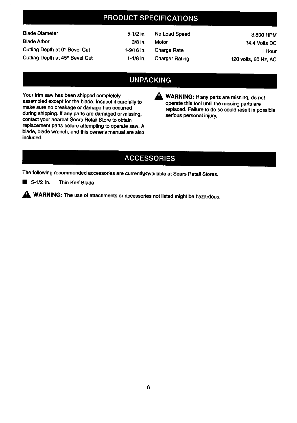
Blade Diameter
Blade Arbor
Cutting Depth at 0° Bevel Cut
Cutting Depth at 45 ° Bevel Cut
5-1/2 in.
318in.
1-9/16 in.
1-1/8 in.
No Load Speed
Motor
Charge Rate
Charger Rating
3,800 RPM
14.4 Volts DC
1 Hour
120 volts, 60 Hz, AC
Your trim saw has been shipped completely
assembled except for the blade. Inspect itcarefully to
make sure no breakage or damage has occurred
during shipping. If any parts are damaged or missing,
contact your nearest Sears Retail Store to obtain
replacement parts before attempting to operate saw. A
blade, blade wrench, and this owner's manual are also
included.
The following recommended accessories are currently,l_vailable at Sears Retail Stores.
• 5-1/2 in. Thin Kerr Blade
,_ WARNING: The use of attachments oraccessories not listed might be hazardous.
_I_ WARNING: If any parts are missing, do not
operate this tool until the missing parts are
replaced. Failure to do so could result in possible
serious personal injury.
Page 7

CHARGER
See Figure 2.
Your charger has a =.keyhole" hanging feature for
convenient, space saving storage. Screws should be
installed so that center distances are 1-7/16 inches
apad.
YELLOWANDGREENLIGHT
INDICATESOFTSTARTMODE
GREENLIGHT"ON"
REDUGHT"ON"INDICATES
FASTCHARGINGMODE
BATrERY
CHARGER
BATrERYPACK
1-7/16in.
BACKSIDEOFCHARGER
Fig. 2
IMPORTANT INFORMATION FOR RECHARGING HOT BATTERIES
When using your trim saw continuously, the batteries in your battery pack will become hot. You should let a hot
battery pack cool down for approximately 30 minutes before attempting to recharge. When the battery pack
becomes discharged and is hot, this will cause the yellow and green lights on your battery charger to come on
instead of the red light. The yellow and green lights indicate soft start mode and will switch to green only, indicat-
ing slow charge mode. The red light indicates fast charge mode, I hour charge time. The green light indicates
slow charge m_ode, requiring overnight charging for batteries to reach full charge. If the green light comes on
after letting battery pack cool down, remove itfrom charger for additional cooling. Once the battery pack cools
down, you can recharge battery pack in fast charge mode as normal. Do not leave a hot battery pack in charger
until itcools down. The green light will not go off when battery pack cools. If fast charge mode is desired, you
must physically remove a hot battery pack from the charger, let itcool, then place it back in charger after it has
cooled down.
Note: This situation only occurs when continuous use of your saw causes the batteries to become hot. It does
not occur under normal circumstances. Refer to "CHARGING YOUR TRIM SAW" for normal recharging of
batteries. If the charger does not charge your battery pack under normal circumstances, return both the battery
pack_andcharger to your nearest Sears repair center for electrical check.
7
Page 8

KNOWYOURTRIMSAW
See Figure 2.
Before attempting to use any tool familiarize yourself
with all operating features and safety requirements.
Features include easily operated bevel cut and depth
of cut adjustment mechanisms; positive O° bevel stop;
spindle lock; and blade wrench storage.
_, WARNING: If any parts are missing, do not
operate tool until the missing parts are replaced.
Failure to do so could result in possible serious
personal injury.
GUIDESCREW
(WINGSCREW)
SWITCH
See Figure 2.
Your saw is equipped with a lock-off button which
reduces the possibilityof accidental starting. The lock-
off button is located on the handle above the switch
tdgger. You must depress the lock-off button in order
to pull the switch trigger. The lock resets each time
the trigger is released. Note: You can depress the
lock-off button from either the left or right side.
APPLICATIONS
(Use only for the purpose listed below)
• Cutting all types of wood products (lumber,
plywood, paneling).
RIP
LOCK-OFF
BU'I'rON
SPINDLE
LOCKBUTTON
BLADEWRENCH
STORAGEAREA
(DEPTHADJUSTMENTKNOB)
(BEVELADJUSTMENTKNOB)
DEPTHOF
CUTADJUSTMENT
RIP
GUIDESCREW
(WINGSCREW)
BEVELCUT
ADJUSTMENT
BASE
ASSEMBLY
BLADE
SWITCH
TRIGGER
UPPER
BLADEGUARD
LOWER
BLADEGUARD
RIPGUIDE
8
Page 9

_k WARNING: Always wear safety goggles or
safety glasses with side shields when operating
tools. Failure to do so could result in .objects
being thrown into your eyes, resulting in possible
serious injury.
_k WARNING: Do not allow familiarity with your
trim saw to make you careless. Remember that a
careless fraction of a second is sufficient to inflict
severeinjury.
CHARGING YOUR TRIM SAW
The battery pack for th!stool has been shipped in a
low charge condition to prevent possible problems.
Therefore, you should charge it until light on front of
charger changes from red to green.
Note: Batteries will not reach full charge the first time
they are charged. Allow several cycles (cutting
followed by recharging) for them to become fully
charged.
TO CHARGE
• Charge battery pack only with the charger
provided.
• Make sure power supply Is normal house
voltage, 120 volts, 60 Hz, AC only.
• Connect charger to power supply.
• Place battery pack in charger aligning raised rib in
charger with groove in battery pack.
• Press down on battery pack to be sure contacts on
battery pack engage properly with charger
contacts.
• Normally, the yellow and green lights on charger
will come on. This indicates charger is in soft start
mode and should switch to fast charge mode within
5 minutes. When charger is in fast charge mode
the red lightwill come on. If after a period of 15
minutes the yellow and green lights remain on,
remove battery pack, wait 1 minute and reinsert
battery pack in charger. Ifthe yellow and green
lights continue to remain on after an additional 15
minutes, the battery pack is damaged and willnot
accept a charge. Return battery pack to your
nearest Sears Repair Center for checking or
replacing.
• When your battery pack becomes fully charged, the
red lightwill turn OFF and the green light will turn
ON.
• After normal usage, 1 hour of charging time is
required to be fully charged. A minimum charge
time of 1-1/2 hours is required to recharge a
completely discharged tool•
• The battery pack will become slightly warm to the
touch while charging. This is normal and does not
indicate a problem.
• Do not place charger in an area of extreme heat or
• /
cold. Itwill work best at normal roomtemperature,
,_ C_UTION: Your battery pack contains sp_cial
high temperature batteries to help prevent battery
damage when left on charge for extended periods
oftime. However, once the batteries become fully
charged, we recommend that you unplug your
charger from power supply and remove the
b4?tterypack.
Page 10

_i, WARNING: Always remove battery pack from
your saw when you are assembling parts, making
adjustments, assembling or removing blades,
cleaning, or when not in use. Removing battery
pack will prevent accidental starting that could
cause sedous personal injury.
TO REMOVE BATI'ERY PACK
• Locate latches on end of battery pack and
depress to release battery pack from your saw.
See Figure 3.
DEPRESSLATCHESTO
RELEASEBATTERYPACK
LATCHES
BATrERY
PACK
WARNING: A 5-1/2 in. blade is the maximum
blade capacity of your saw, Never use a blade
that is too thick to allow outer blade washer to
engage withthe flats on the spindle. Larger
blades will come in contact with the blade guard,
while thicker blades will prevent blade screw
from securing blade on spindle. Either of these
situations could result in a sedous accident.
TO ASSEMBLE OR REMOVE BLADE
TO ASSEMBLE BLADE:
• Remove battery pack from saw.
_k WARNING: Failure to remove battery pack from
saw could result in accidental starting causing
possible serious personal injury.
• Locate latcheson end of battery pack and depressto
release battery pack fromyour saw. See Figure 3.
• Remove blade wrench (5 mm hex key) from
storage area. See Figure 2.
• Depress spindle lock button and remove blade
screw and outer blade washer. See Figqre 4.
Fig. 3
• Remove battery pack from your saw.
TO INSTALL BATFERY PACK
See Figure 3.
• Place battery pack in your saw. Align raised rib
inside saw with groove on battery pack.
• Make sure the latches on each side of your
battery pack snap in place and battery pack is
secured in saw before beginning operation.
A CAUTION: When placing battery pack in your
saw, be sure raised rib inside saw aligns with
groove on battery pack and latches snap in place
properly. Improper assembly of battery pack can
cause damage to internal components.
INNER
LOWER OUTER BLADE
BLADE BLADE SCREW
GUARD BLADE WASHER
HANDLE Fig. 4
Note: Turn blade screw clockwiseto remove.
• Wipe a drop of oil onto inner blade washer and
outer blade washer where they contact blade,
A
WARNING: If inner blade washer has been
removed, replace it before placing blade on
spindle. Failure to do so could cause an accident
since blade will not tighten propedy.
10
Page 11

• Fit saw blade inside lower blade guard and onto
spindle. Note: The saw teeth point upward at the
front of saw as shown in figure 4.
• Replace outer blade washer.
• Depress spindle lock button, then mplaoe blade
screw. Tighten blade screw securely.
Note: Turn blade screw countemlockwise to tighten.
• Return blade wrench to storage area.
REMEMBER: Never use a blade that Is too thick to
allow the outer blade washer to engage with the
flats on the spindle.
TO REMOVE BLADE:
• Remove battery pack from saw.
A WARNING: Failure to remove battery pack irom
saw could result in accidental starting causing
possible serious personal injury.
SAW BLADES
The best of saw blades willnot cut efficiently ifthey
are not kept clean, sharp, and properly set. Using a
dull blade will place a heavy load on your saw and
increase the danger of kickback. Keep extra blades on
hand, sothat sharp blades are always available.
Gum and wood pitch hardened on blades will slow
your saw down. Use gum and pitch remover, hot
water, or kerosene to remove these accumulations. Do
not use gasoline.
BLADE GUARD SYSTEM
The lower blade guard attached to your trim saw Is
there for your protection and safety. It should
never be altered for any reason. If It becomes
damaged or begins to return slow or sluggish, do
not operate your saw until the damage has been
repelred or replaced. Always leave guard In
operating position when using saw.
• Remove blade wrench from storage area. See
Figure 2.
• Position your saw as shown in figure 5, depress
spindle lock button, and remove blade screw.
Note: Turn blade screw clockwise to remove.
• Remove outer blade washer. See Figure 4.
Note: Blade can be removed at this polnL
SPINDLE
LOCKBuTroN
BLADE
SCREW
BLADE
WRENCH
Fig. 5
A DANGER: When sawing through workpiece,
lower blade guard does not cover blade on the
underside of workpiece. Since blade is exposed
on underside ofworkpiece, keep hands and
fingers away from cutting area. Any part of your
body coming in contact with moving blade wilt
result in sedous injury. See Figure 6.
LOWERBLADEGUARD
ISIN UP POSITION
WHENMAKINGA CUT
BLADEEXPOSEDON
UNDERSIDEOFWORKPIECE
Fig. 6
Never use saw when guard is not operating
correctly. Guard should be checked for correct
operation before each use. If you drop your saw,
check the lower blade guard and bumper for
damage at all depth settings before reuse.
Note: The guard is operating correctly when It
moves freely and readily returns to the closed
position. If for any reason your lower blade guard
does not close freely, take it to the nearest Sears
Parts and Repair Center for service before using.
/
11
Page 12

KICKBACK
See Figure 7.
TO LESSEN THE CHANCE OF KICKBACK:
• Always keep the correct blade depth setting - the
correct blade depth setting for all cuts should not
exceed 1/4 in. below the material to be cut. See
Figure 9. One blade tooth below the matedal to be
cut works best for most efficient cutting action.
KICKBACK
BLADESETTOO DEEP
The best guard against kickback Is to avoid
dangerous Idractlces.
Kickbackoccurs when the blade stalls rapidly and the
saw is driven back towards you, Blade stalling is
caused by any action which pinches the blade in the
wood.
_k DANGER: Release switch immediately ifblade
binds or saw stalls. Kickback could cause you to
lose control of your saw. Loss of controlcan lead j,,
to serious injury.
KICKBACK IS CAUSED BY:
• Incorrect blade depth setting. See Figure 7.
• Sawing into knots or nails in workpiece.
• Twisting blade while making a cut.
• Making a cut with a dull, gummed up, or impropedy
set blade.
• Incorrectly supporting workpiece. See Figure 8.
Fig. 7
CORRECTBLADEDEPTHSETTING=
BLADEEXPOSEDONE BLADETOOTH
BELOWTHEMATERIALTO BEcur Fig. 9
• Inspect the workpiece for knots or nails before
beginning a cut. Never saw into a knot or nail.
• Make straight cuts. Always use a straight edge
gulch,when ripcutting. This helps prevent twisting
the'btade in the cut.
• Always use clean, sharp and properly set blades.
Never make cuts with,dull blades.
• To avoid pinching the blade, supportthe workpiece
propedy before beginning a cut, The dght and
wrong ways to support large pieces of work are
shown in figures 8 and_lO.
WRONG
• Forcing a cut.
• Cutting warped or wet lumber.
• Tool misuse or incorrect operating procedures.
RIGHT Fig.lO
Fig. 8
12
Page 13

• When making a cut use steady, even pressure.
Never force cuts.
• Do not cut warped or wet lumber.
• Always hold your saw firmly with both hands and
keep your body in a balanced position so as to
resist the forces of kickback should it occur.
When using your saw, always stay alert and
exercise control. Do not remove your saw from
workpiece while the blade Is moving.
DEPTH OF CUT ADJUSTMENT
Always keep correct blade depth setting. The correct
blade depth setting for all cuts should not exceed 1/4
inch below the material to be cut. More blade depth
will increase the chance of kickback and cause the cut
to be rough. One blade tooth below the material to be
cut works best for most efficient cutting action.
TO ADJUST BLADE DEPTH
• Remove battery pack from saw.
,_ WARNING: Failure to remove battery pack from
saw could result in accidental starting causing _"
possible serious personal injury.
STARTING A CUT
Know the right way to use your saw.
See Figure 12.
RIGHT
Never useyour saw as shown infigure 13.
Fig. 12
DEPTH
BASE ADJUSTMENT
ASSEMBLY KNOB
• Loosen depth adjustment knob. See Figure 11.
• Hold base flat against the workpiece and raise or
lower saw*until the required depth is reached.
• Tighten depth adjustment knob securely.
Fig. 11
WRONG
Fig. 13
Never place your hand on the workp|ece behind
your saw while making a cut.
_i_ WARNING: To make sawing easier and safer,
always maintain proper controlof your saw. Loss
of controlof your saw could cause an accident
resulting in possible serious injury.
13
Page 14

TO HELP MAINTAIN CONTROL:
• Always support your workpiece near the cut.
• Support your workpiece so the cut will be on yo=;r
left.
• Clamp your workpiece so itwill not move during the
cut.
Place your workpiece with its good side down.
Note: The good side is the side on which appearance
is important.
Before beginning a cut, draw a guideline along the
desired line of cut. Then place front edge of base on
that part of your workpiece that is solidilysupported.
See Figure 12.
Never place your saw on that part of the
workplece that will fall off when the cut Is made.
See Figure 14.
RIGHT Fig. 15
Depress the lock-off button and squeeze the switch
trigger to start your saw. Always let the blade reach
full speed, then guide your saw into the workpiece.
WRONG
Hold your saw firmly with both hands.
See Figure 15.
Fig. 14
_l, WARNING: The blade coming in contact with
the workpiece before it reaches full speed could
cause your saw to "kickback"towards you*.
re,suiting in serious injury.
When making a cut use steady, even pressure.
Forcing _auses rough.cuts, could shorten the life of
your saw and could cause "kickback."
REMEMBER:
Whel_ sewing through work, the lower blade guard
does not cover the blade, exposing It on the
underside of work. Keep your hands and fingers
away from'cutting area. Any part of your body
coming In contact with the moving blade will
result In;serious Injury.
After you complete your cut release the trigger and
allow the blade to come to a complete stop. Do not
remove your saw from workplece while the blade
is moving.
_k CAUTION: When lifting your saw from the.
workpiece, the blade is exposed on the
underside of your saw until the lower blade guard
closes. Make sure lower blade guard is closed
before setting your saw down on work surface.
TO CROSS CUT OR RIP CUT
When making a cross cut or rip cut, align your line of
cut with the outer blade guide notch on the saw base
as shown in figure 16.
14
Page 15

TOPVIEWOFSAW GUIDELINE
AUGNOUTERBLADEGUIDENOTCHONSAWBASEWITH
UNEOFCUTASSHOWNWHENMAKINGCROSSCUTSOR
RIPCUTS Fig.16
Since blade thicknesses vary, always make a trial cut
in scrap material along a guideline to determine how
much, if any, the guideline must be offset to produce
an accurate cut. Note: The distance from the line of
cut to the guideline is the amount you should offset
the guideline.
WIDTH OF CUT SCALE
See Figure 17.
RIP GUIDE (EDGE GUIDE)
Use the rip guide provided with your saw when
making wide rip cuts. A five inch scale has been
provided on the rip guide. When using the width of cut
scale on the base in combination with the rip guide,
cuts can be made up to 6 in. to the leftof the blade or
8-3/4 in. to the right of the blade.
The rip guide helps prevent the blade from twisting in
a cut. The blade twisting in a cut can cause kickback.
TO ASSEMBLE RIP GUIDE
• Remove battery pack from saw.
& WARNING: Failure to remove battery pack from
saw could result in accidental starting causing
possible serious personal injury.
RIP
GUIDESCREW
BASE
ASSEMBLY
WIDTHOF
CUTSCALE
BLADE
Fig. 17
A width of cut scale has been provided on the base of
your saw. When making straight cross cuts or rip cuts,
the scale can be used to measure up to four inches to
the right side of the blade. It can be used to measure
up to one inch to the left side of the blade.
RIPGUIDE
(EDGEGUIDE)
PLACERIP
GUIDETHRUHOLES i,
Fig. 18
• Place lip guide through holes in saw base as
shown in figure 18.
• Adjust rip guide to the width needed.
• Tighten ripguide screw (wing screw) securely.
When using a ripguide, position the face of the dp
guide firmly against the edge of workpiece. This
makes for a true cut without pinching the blade. The
guiding edge of workpiece must be straight for your
cut to be straight. Use caution to prevent the blade
from binding in the cut.
15
Page 16

TO BEVEL CUT
The angle of cut of your saw may be adjusted to any
desired setting between zero and 50 °. Note: When
making cuts at 50 °, blade should be set at full depth of
cut.
When making 45° bevel cuts, there is a notch in the
saw base to help you line up the blade with the line of
cut. See Figure 19.
BEVEL BEVEL
SCALE ADJUSTMENT
KNOB
When making a bevel cut hold your saw firmlywith
both hands as shown in figure 20.
LOWER
BLADEGUARD
Fig. 20
BLADE
GUIDENOTCH
GUIDEUNE
AUGNINNERBLADEGUIDENOTCHONSAWBASEWITH
UNE OFCUTASSHOWNWHENMAKING45° BEVELCUTS
Fig. 19
Align your line of cut with the inner blade guide notch
on the saw base when making 45° bevel cuts.
Since blade thicknesses vary and different angles
require different settings, always make a trial cut
in scrap material along a guideline to determine
how much you should offset the guideline on the
board to be cut.
Rest the front edge of the base on the workpiece.
Depress the lock-off button and squeeze the switch
tdgger to start your saw. Always let the blade reach
full speed, then guide your saw into the wotkpiece.
_k WARNING: The blade coming in contact with
the workpiece before it reaches full speed _€ould
sC_USesaw to "kickback"toward you resultlhg in
rious injury.
After yoa complete your cut release the tdgger and
allow the blade to come,to a complete stop. After the
blade has stopped, liftyour saw from the workpiece.
TO ADJUST BEVEL SEI"FING
• Remove battery packtfrom saw.
WARNING: FailuPeto remove battery pack from
sawcould result in accidental starting causing
pos_ible sedous personal injury.
• Loosen bevel adjustment knob. See Figure 19.
II Raise motorhousing end of saw untilyou reach
desired angle settingon bevel scale. See Figure 19.
• Tighten bevel adjustment knob securely.
16
WARNING: Attempting bevel cut without knob
securely tightened can result in sedous injury.
Page 17

POSITIVE 0° BEVEL STOP
See Figure 21.
ADJUSTMENT BEVEL
SCREW ADJUSTMENT
KNOB
HEXNUT
BLADE
POSITIVE0° BEVELSTOP
T
COMBINATION
SQUARE
• Turn screw and adjust base untilsquare with saw
blade.
• Tighten hex nut and bevel adjustmentknob securely.
WARNING: Attempting to make cuts without
bevel adjustment knob securely tightened can
result in serious injury.
TO POCKET CUT
See Figure 22.
& WARNING: Always adjust bevel settingtozero
beforemaking a pocketcut. Attempting a pocket
cutat any other settingcan resultin lossof control
ofyoursaw possiblycausing seriousinjury.
Adjust the bevel setting to zero, set blade to correct
blade depth setting, and swing the lower blade guard
up using the lower blade guard handle.
Always raise the lower blade guard with the
handle to avoid serious Injury.
While holding lower blade guard by the handle, firmly
_f4
restthe front of the base fiat against the workpieca
with the rear of the handle raised so the blacJedoes
not touch the workpieca. See Figure 22.
Fig. 21
Your saw has a positive O° bevel stop, that has been
factory adjusted to assure O° angle of your saw blade
when making 90° cuts. However, misalignmant can
occur dudng shipping.
TO CHECK
• Remove battery pack from saw.
,_ WARNING: Failure to remove battery pack from
saw could result in accidental starting causing
possible serious personal injury.
• Place your saw in an upside down position on
workbench. See Figure 21.
• Using a combination square, check squareness of
saw blade to the base of your saw.
TO ADJUST-
• Remove battery pack from saw.
A WARNING: Failure to remove battery pack from
saw could result in accidental starting causing
possible sedous personal injury.
• Loosen bevel adjustment knob.
• Loosen hex nut secudng adjustment screw.
f' LOWERBLADE
GUARDHANDLE
LOWER
BLADEGUARD
POCKETCUT
Depress the lock-off button and squeeze the switch
tdgger to start your saw. Always let the blade reach
full speed then slowly lower blade into the
workplece until base Is flat against workplece.
After you complete your cut release the tdgger and allow
the blade to come to a complete stop.After the blade
has stopped, remove itfrom the workpiece. Comers
may than be cleared out witha hand saw or sabre saw.
_k WARNING: Never tie the lower blade guard in
raised position. Leaving the blade exposed could
lead to sedous injury.
17
Fig. 22
a
Page 18

18
Page 19

,_ WARNING: When servicing, use only identical
Craftsman replacement parts. Use of any other
part may create a hazard or cause product
damage.
Avoid using solvents.when cleaning plastic pads.
Most plastics are susceptible to damage from various
types of commercial solvents and may be damaged
by their use. Use clean cloths to remove dirt, dust, oil,
grease, etc,
_ WARNING: Do not at any time let brake fluids,
gasoline, petroleum-based products, penetrating
oils, etc. come in contact with plastic parts. They
contain chemicals that can damage, weaken or
destroy plastic.
Do not abuse power tools. Abusive practices can
damage tool as well as workpiece.
Only the parts shown on parts list,page twenty one,
are intended to be repaired or replaced by the
customer. All other parts should be replaced by a
qualified service technician at an authorized service
facility.
WARNING: Do not attempt to modify this tool or
create accessodes not recommended for use
with this tool. Any such alteration or modification
is misuse and could result in a hazardous
condition leading to possible serious personal
injury.
BA'R'ERIES
Your saw's battery pack is equipped with 12 nickel-
cadmium rechargeable battedes. Length of service
from each charging will depend on the type of work
you are doing.
The battedes in this tool have been designed to
provide maximum trouble free life. However, like all
batteries, they will eventually wear out. Do not
disassemble battery pack and attempt to replace the
battedes. Handling of these bettedes, especially when
wearing dngs and jewelry, could result in a sedous
bum.
To preserve natural resources, please
recycle or dispose of expired battery
pack propedy.
This product contains nickel-cadmium
battery. Must be disposed of properly.
Local, state, or federal laws may
prohibit disposal of nickel-cadmium
batteries in ordinary trash. Consult
your local waste authority for
information regarding available
recycling end/or disposal options.
To obtain the longest possible battery life, we suggest
the following:
• Store and charge your battedes in a cool area.
Temperatures above normal room temperature
will shorten battery life.
• Never store batteries in a discharged condition.
Recharge them immediately after they are
discharged.
• All battedes gradually lose their charge. The
higher the temperature the quicker they lose their
charge. If you store your toot for long pedods of
time without using it, recharge the battedes every
month or two. This prectlce willprolong battery.
I
BATTERY PACK REMOVAL AND
PREPARATION FOR I_ECYCLING
_i, WARNING: Upon,removal, cover the battery
pack's terminals with heavy duty adhesive tape.
Do r_t attempt to destroy or disassemble battery
pack or remove any of its components. Nickel-
cadmium batteries must be recycled or disposed
of properly. Also, never touch both terminals with
metal objects and/or body parts as short circuit
may result. Keep away from children. Failure to
comply with these wamings could result in fire
and/or sedous injury.
19
Page 20

CRAFTSMAN CORDLESS TRIM SAW - MODEL NUMBER 315.269600
27
6
12
•_26
O
14
18 28
19 20 23
10 21 22
[ 24
5
"2 _ 2_ ' 25
20
Page 21

CRAFTSMAN CORDLESS TRIM SAW- MODEL NUMBER 315.269600
The model number will be found on a plate attached to the motor housing. Always mention the model number in all correspondence regarding your
CORDLESS TRIM SAW or when ordering repair pads.
I
SEE BACK PAGE FOR PARTS ORDERING INSTRUCTIONS
PARTS LIST
]
Key
No.
1
2
3
4
5
6
7
8
9
10
11
12
13
14
15
Part
Number
975546-000
975547-000
975544-000
975548-000
975552-000
975551-000
975549-000
975559-000
975558-000
975550-000
980057-001
975557-000
975545-000
975543-000
975542-000
Description Quan.
Carriage Bolt (M6 x 102 ram) ..........._............. 1
Base Assembly ............................................... 1
Lock Nut ......................................................... 2
Knob ............................................................... 2
Spring ............................................................. 1
Wing Screw .................................................... 1
Base Screw .................................................... 1;
Hex Nut .......................................................... 1
Screw ............................................................. 1
Cardage Bolt (M6 x 13 mm) ........'................... 1' .,.
Data Plate ............ _.,.................................. ",....1
Waming Label. ............... i............................... 1
Upper Blade Guard ........................................ 1
Upper Blade Guard Screw ...................... :...... 3
Bumper .......................... :'"'"r .............. :"........ 1
Key Part
No. Number
16 975541-000
17 975540-000
18 975539-000
19 975538-000
20 975537-000
21 975536-000
22 975534-000
23 975419-001
24 975533-000
25 975532-000
26 980011-000
27 977405-000
28 975554-000
29 975553-000
30 980058-000
972000-561
DescrlpUon Quan.
Bumper Screw ................................................ 1
Spring ............................................................. 1
Lower Blade Guard ........................................ 1
• Ball Bearing (NTN #6200LB) ......................... 1
Bearing Retainer ............................................ 1
Bearing Retainer Screw ................................. 3
Inner Blade Washer ....................................... 1
Saw Blade ...................................................... 1
Outer Blade Washer ....................................... 1
Blade Screw ................................... i............... 1
* Battery Pack (Item No. 9-11062) ................... 1
* Charger (item No. 9-11063) ........................... 1
Rip Guide ....................................................... 1
Blade Wrench (5 mm Hex Key) ..................... 1
Carrying Case - Not Shown ........................... 1
Owner's Manual
* Can Be Purchased Thru RSOS (Retail Special Order System)
21
Page 22

For in,home major brand repair service:
Call 24 hours a day, 7 days a week
1-800-4-MY-Home s. (1-800-469-4663)
Para peoir servicio de reparacibn a domicilio - 1-800-676-5811
In Canada for all your service and parts needs call
Au Canada pour tout le service ou les pi_ces
For the repair or replacement parts you need:
Call 7 am - 7 pro, 7 days a week
1-800-366-PART (1-800-366-7278)
Para ordenar piezas con entre_a a domicilio - 1-800-659-7084,
For the location of a Sears Parts and I_epair Center in your area:
Call 24 hours a day, 7 days a week
- 1-800-665-4455
1-800-488-1222
For information on purchasing a Sears MaintenanCe Agreement
or to inquire about an existing Agreement:
Call 9 am - 5 pm, Monday :- Saturday
1-800-827-6655 "
J
The Service Side of Sears s"
 Loading...