

Page 1
Operator's Manual
ROUTER
Double Insulated
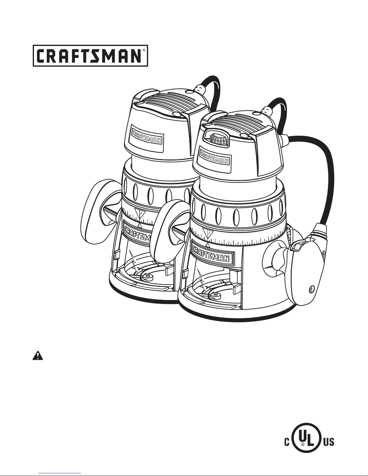
Model Nos.
315.175101
315.175111
1/32
A
1
0
2
15/32
7/16
3/8
2
3
/
3
1
1/32
1
0
2
15/32
7/16
3/8
2
3
/
3
1
Save this manual for
future reference
CAUTION: Read and
follow all Safety Rules and
Operating Instructions before
first use of this product.
Customer Help Line: 1-800-932-3188
Sears, Roebuck and Co., 3333 Beverly Rd., Hoffman Estates, IL 60179 USA
Visit the Craftsman Web page: www.sears.com/craftsman
983000-430
6-04
315.175101
315.175111
• Safety
• Features
• Operation
• Maintenance
• Parts List
Page 2

TABLE OF CONTENTS
■ Warranty .............................................................................................................................................................2
■ Introduction ......................................................................................................................................................... 2
■ General Safety Rules ..................................................................................................................................... 3-4
■ Specific Safety Rules ......................................................................................................................................... 4
■ Symbols .............................................................................................................................................................. 5
■ Specifications .....................................................................................................................................................6
■ Unpacking...........................................................................................................................................................6
■ Features ......................................................................................................................................................... 7-8
■ Adjustments .................................................................................................................................................. 9-11
■ Operation .................................................................................................................................................... 12-17
■ Maintenance .....................................................................................................................................................18
■ Accessories ......................................................................................................................................................19
■ Exploded View and Repair Parts List ......................................................................................................... 20-21
■ Parts, Ordering, and Service ............................................................................................................................22
WARRANTY
FULL ONE YEAR WARRANTY ON ROUTER
If this Router fails to give complete satisfaction within one year from the date of purchase,
RETURN IT TO THE NEAREST SEARS STORE IN THE UNITED STATES, and Sears will repair it, free of
charge.
If this Router is used for commercial or rental purposes, this warranty applies for only 90 days
from the date of purchase.
This warranty gives you specific legal rights, and you may also have other rights which vary from state to state.
Sears, Roebuck and Co., Dept. 817 WA, Hoffman Estates, IL 60179
INTRODUCTION
Your router has many features for making routing
operations more pleasant and enjoyable. Safety,
performance and dependability have been given top
priority in the design of this router making it easy to
maintain and operate.
Look for this symbol to point out important safety precautions. It means attention!!!
Your safety is involved.
CAUTION: Carefully read through this entire
operator's manual before using your new router.
Pay close attention to the Rules for Safe
Operation, Warnings and Cautions. If you use
your router properly and only for what it is
intended, you will enjoy years of safe, reliable
service.
WARNING:
eyes, which can result in severe eye damage. Before beginning power tool operation,
always wear safety goggles or safety glasses with side shields and a full face shield when
needed. We recommend Wide Vision Safety Mask for use over eyeglasses or standard
safety glasses with side shields, available at Sears Retail Stores. Always wear eye
protection which is marked to comply with ANSI Z87.1.
The operation of any router can result in foreign objects being thrown into your
2
Page 3

GENERAL SAFETY RULES
WARNING: Read and understand all
instructions. Failure to follow all instructions
listed below, may result in electric shock, fire
and/or serious personal injury.
SAVE THESE INSTRUCTIONS
WORK AREA
■ Keep your work area clean and well lit. Cluttered
benches and dark areas invite accidents.
■ Do not operate power tools in explosive atmospheres, such as in the presence of flammable
liquids, gases, or dust. Power tools may create
sparks which may ignite the dust or fumes.
■ Keep bystanders, children, and visitors away
while operating a power tool. Distractions can
cause you to lose control.
ELECTRICAL SAFETY
■ Double insulated tools are equipped with a
polarized plug (one blade is wider than the
other). This plug will fit in a polarized outlet only
one way. If the plug does not fit fully in the
outlet, reverse the plug. If it still does not fit,
contact a qualified electrician to install a polarized outlet. Do not change the plug in any way.
Double insulation eliminates the need for the
three-wire grounded power cord and grounded
power supply system.
■ Avoid body contact with grounded surfaces, such
as pipes, radiators, ranges, and refrigerators.
There is an increased risk of electric shock if your
body is grounded.
■ Don’t expose power tools to rain or wet conditions. Water entering a power tool will increase the
risk of electric shock.
■ Do not abuse the cord. Never use the cord to carry
the tools or pull the plug from an outlet. Keep cord
away from heat, oil, sharp edges, or moving parts.
Replace damaged cords immediately. Damaged
cords increase the risk of electric shock.
■ When operating a power tool outside, use an outdoor extension cord marked “W-A” or “W”. These
cords are rated for outdoor use and reduce the risk of
electric shock.
PERSONAL SAFETY
■ Stay alert, watch what you are doing and use
common sense when operating a power tool.
Do not use tool while tired or under the influence of drugs, alcohol, or medication. A moment
of inattention while operating power tools may
result in serious personal injury.
■ Dress properly. Do not wear loose clothing or
jewelry. Contain long hair. Keep your hair,
clothing, and gloves away from moving parts.
Loose clothes, jewelry, or long hair can be caught in
moving parts.
■ Avoid accidental starting. Be sure switch is off
before plugging in. Carrying tools with your finger
on the switch or plugging in tools that have the
switch on, invites accidents.
■ Remove adjusting keys or wrenches before
turning the tool on. A wrench or a key that is left
attached to a rotating part of the tool may result in
personal injury.
■ Do not overreach. Keep proper footing and
balance at all times. Proper footing and balance
enables better control of the tool in unexpected
situations. Do not use on a ladder or unstable
support.
■ Use safety equipment. Always wear eye protection. Dust mask, non-skid safety shoes, hard hat,
or hearing protection must be used for appropriate
conditions.
TOOL USE AND CARE
■ Use clamps or other practical way to secure
and support the workpiece to a stable platform.
Holding the work by hand or against your body is
unstable and may lead to loss of control.
■ Do not force tool. Use the correct tool for your
application. The correct tool will do the job better
and safer at the rate for which it is designed.
■ Do not use tool if switch does not turn it on or
off. Any tool that cannot be controlled with the
switch is dangerous and must be repaired.
■ Disconnect the plug from power source before
making any adjustments, changing accessories, or storing the tool. Such preventive safety
measures reduce the risk of starting the tool
accidentally.
■ Store idle tools out of the reach of children and
other untrained persons. Tools are dangerous in
the hands of untrained users.
■ Maintain tools with care. Keep cutting tools
sharp and clean. Properly maintained tools with
sharp cutting edges are less likely to bind and are
easier to control.
■ Check for misalignment or binding of moving
parts, breakage of parts, and any other condition that may affect the tool’s operation. If
damaged, have the tool serviced before using.
Many accidents are caused by poorly maintained
tools.
■ Use only accessories that are recommended by
the manufacturer for your model. Accessories
that may be suitable for one tool, may become
hazardous when used on another tool.
3
Page 4

GENERAL SAFETY RULES
SERVICE
■ Tool service must be performed only by qualified repair personnel. Service or maintenance
performed by unqualified personnel could result in
a risk of injury.
■ When servicing a tool, use only identical replacement parts. Follow instructions in the
Maintenance section of this manual. Use of
unauthorized parts or failure to follow Maintenance
Instructions may create a risk of electric shock or
injury.
SPECIFIC SAFETY RULES
Hold tool by insulated gripping surfaces when performing an operation where the cutting tool may
contact hidden wiring or its cord. Contact with a “live” wire will make exposed metal parts of the tool “live” and
shock the operator.
ADDITIONAL RULES FOR SAFE OPERATION
■ Know your power tool. Read operator’s manual
carefully. Learn its applications and limitations,
as well as the specific potential hazards related
to this tool. Following this rule will reduce the risk
of electric shock, fire, or serious injury.
■ Always wear safety glasses. Everyday eyeglasses have only impact-resistant lenses; they
are NOT safety glasses. Following this rule will
reduce the risk of serious personal injury.
■ Protect your lungs. Wear a face or dust mask if
the operation is dusty. Following this rule will
reduce the risk of serious personal injury.
■ Protect your hearing. Wear hearing protection
during extended periods of operation. Following
this rule will reduce the risk of serious personal
injury.
■ Inspect tool cords periodically and, if damaged,
have repaired at your nearest authorized service center. Constantly stay aware of cord
location. Following this rule will reduce the risk of
electric shock or fire.
■ Check damaged parts. Before further use of the
tool, a guard or other part that is damaged
should be carefully checked to determine that it
will operate properly and perform its intended
function. Check for alignment of moving parts,
binding of moving parts, breakage of parts,
mounting, and any other conditions that may
affect its operation. A guard or other part that is
damaged should be properly repaired or replaced by an authorized service center. Follow-
ing this rule will reduce the risk of shock, fire, or
serious injury.
■ Do not abuse cord. Never carry the tool by the
cord or yank it to disconnect it from the receptacle. Keep cord away from heat, oil, and sharp
edges. Following this rule will reduce the risk of
electric shock or fire.
■ Make sure your extension cord is in good
condition. When using an extension cord, be
sure to use one heavy enough to carry the
current your product will draw. A wire gage size
(A.W.G.) of at least 16 is recommended for an
extension cord 100 feet or less in length. A cord
exceeding 100 feet is not recommended. If in
doubt, use the next heavier gage. The smaller
the gage number, the heavier the cord. An
undersized cord will cause a drop in line voltage
resulting in loss of power and overheating.
■ Inspect for and remove all nails from lumber
before routing. Following this rule will reduce the
risk of serious personal injury.
■ Drugs, alcohol, medication. Do not operate tool
while under the influence of drugs, alcohol, or
any medication. Following this rule will reduce the
risk of electric shock, fire, or serious personal injury.
■ Save these instructions. Refer to them frequently and use them to instruct others who
may use this tool. If you loan someone this tool,
loan them these instructions also.
WARNING: Some dust created by power
sanding, sawing, grinding, drilling, and other
construction activities contains chemicals known
to cause cancer, birth defects or other
reproductive harm. Some examples of these
chemicals are:
• lead from lead-based paints,
• crystalline silica from bricks and cement and
other masonry products, and
• arsenic and chromium from chemicallytreated lumber.
Your risk from these exposures varies,
depending on how often you do this type of work.
To reduce your exposure to these chemicals:
work in a well ventilated area, and work with
approved safety equipment, such as those dust
masks that are specially designed to filter out
microscopic particles.
4
Page 5

SYMBOLS
Important: Some of the following symbols may be used on your tool. Please study them and learn their meaning.
Proper interpretation of these symbols will allow you to operate the tool better and safer.
SYMBOL NAME DESIGNATION/EXPLANATION
V Volts Voltage
A Amperes Current
Hz Hertz Frequency (cycles per second)
W Watt Power
min Minutes Time
Alternating Current Type or a characteristic of current
n
0
.../min Revolutions or Reciprocation Per Minute Revolutions, strokes, surface speed,
The purpose of safety symbols is to attract your attention to possible dangers. The safety symbols, and the
explanations with them, deserve your careful attention and understanding. The safety warnings do not by
themselves eliminate any danger. The instructions or warnings they give are not substitutes for proper accident
prevention measures.
No Load Speed Rotational speed, at no load
Class II Construction Designates double-insulated
construction tools
orbits etc. per minute
Safety Alert Indicates danger, warning or caution.
It means attention!!! Your safety is
involved.
Wet Conditions Alert Do not expose to rain or use in damp
locations.
SYMBOL MEANING
DANGER: Failure to obey a safety warning will result in serious injury to yourself or to others. Always
follow the safety precautions to reduce the risk of fire, electric shock and personal injury.
WARNING: Failure to obey a safety warning can result in serious injury to yourself or to others.
Always follow the safety precautions to reduce the risk of fire, electric shock and personal injury.
CAUTION: Failure to obey a safety warning may result in property damage or personal injury to
yourself or to others. Always follow the safety precautions to reduce the risk of fire, electric shock and
personal injury.
NOTE: Advises you of information or instructions vital to the operation or maintenance of the equipment.
SAVE THESE INSTRUCTIONS
5
Page 6

SPECIFICATIONS
Depth of Cut 0 - 1-1/2 in.
Collet 1/4 in.
Horsepower
Model No. 315.175101 1-1/2
Model No. 315.175111 1-3/4
Ampere
Model No. 315.175101 8.5 Amps
Model No. 315.175111 9.0 Amps
UNPACKING
Your router has been shipped completely assembled.
Inspect it carefully to make sure no breakage or
damage has occurred during shipping. If any parts are
damaged or missing, contact your nearest Sears
Retail Store to obtain replacement parts before
attempting to operate router. A wrench and this
operator's manual are also included.
Input 120 Volts, 60 Hz, AC only
No Load Speed
Model No. 315.175101 25,000/min
Model No. 315.175111 15,000 - 25,000/min
Power Cord 10 ft.
Net Weight
Model No. 315.175101 7 lbs. 3 oz.
Model No. 315.175111 7 lbs. 9.5 oz.
WARNING: If any parts are missing, do not
operate this tool until the missing parts are
replaced. Failure to do so could result in possible
serious personal injury.
6
Page 7

FEATURES
DOUBLE INSULATION
Double insulation is a concept in safety in electric
power tools, which eliminates the need for the usual
three-wire grounded power cord. All exposed metal
parts are isolated from the internal metal motor
components with protecting insulation. Double
insulated tools do not need to be grounded.
Important: Servicing of a tool with double insulation
requires extreme care and knowledge of the system
and should be performed only by a qualified service
technician. For service, we suggest you return the tool
to your nearest authorized service center for repair.
Always use original factory replacement parts when
servicing.
WARNING: The double insulated system is
intended to protect the user from shock resulting
from a break in the tool's internal wiring. Observe
all normal safety precautions to avoid electrical
shock.
ELECTRIC MOTOR
Your router has a precision built electric motor. It
should be connected to a power supply that is 120
volts, 60 Hz, AC only (normal household current).
Do not operate this tool on direct current (DC). A
substantial voltage drop will cause a loss of power
and the motor will overheat. If your tool does not
operate when plugged into an outlet, double-check
the power supply.
SWITCH
To turn the router ON, toggle the switch to the I
position. To turn the router OFF, toggle the switch to
the O position.
SPINDLE LOCK
The spindle lock secures the spindle while you make
adjustments and acts as a retainer to keep the router
body from coming out of the base.
DEPTH ADJUSTING RING
The depth adjusting ring allows you to adjust the
depth of cut.
LOCKING ARM
The locking arm secures the motor housing in the
base.
CHIP SHIELD
A clear plastic chip shield is installed on the front of
your router for protection against flying dust and
chips. The shield is designed to fit the opening of the
router base. If necessary to remove chip shield,
squeeze the tabs on each end and pull outward. To
replace, squeeze the tabs at each end, fit into
opening, then release. For your protection, do not
use router without chip shield properly in place.
Peel the horsepower label from chip shield and
discard.
VARIABLE SPEED
(MODEL NO. 315.175111 ONLY)
See Figure 1.
Your router has advanced electronic features,
designed to assist you in getting the maximum use
from your router. By making proper speed selections,
your router can be adjusted to specific routing needs.
This eliminates much of the guess work previously
needed to perform a given job. Both the experienced
and inexperienced router users benefit, obtaining
professional like results with fewer job errors.
The variable speed control allows the router speed to
be adjusted from 15,000 to 25,000 RPM. The
variable speed control selector is conveniently located
on the top of the motor housing.
Speed can be set according to the approximate cutter
diameter you will be using and to the hardness of the
material being cut. The best cuts are made when the
cutter is fed through material at the proper rate of
feed.
7
Page 8

VARIABLE SPEED DIAL
(MODEL 315.175111)
HANDLE
FEATURES
A
1/32
1
0
2
15/32
7/16
3/8
2
3
/
3
1
SWITCH
CHIP SHIELD
POWER
HANDLE
WRENCH
DEPTH
ADJUSTING RING
DEPTH
INDICATOR RING
1
/
3
2
1
0
2
15/32
7/16
1
3/8
2
3
/
3
LOCKING ARM
SPINDLE LOCK
COLLET NUT
WARNING: Do not allow familiarity with your router to make you careless. Remember that a careless fraction
of a second is sufficient to inflict severe injury.
Fig. 1
8
Page 9

ADJUSTMENTS
WARNING: Your router should never be
connected to power supply when you are
assembling parts, making adjustments, installing
or removing cutters, cleaning, or when not in
use. Disconnecting router will prevent accidental
starting that could cause serious personal injury.
INSTALLING/REMOVING CUTTERS
See Figure 2.
■ Unplug your router.
WARNING: Failure to unplug your router could
result in accidental starting causing serious
injury.
■ Depress spindle lock.
WARNING: To prevent damage to the spindle
or spindle lock, always allow motor to come to a
complete stop before engaging spindle lock.
CUTTER
WRENCH
COLLET
NUT
TO LOOSEN
COLLET NUT
■ Lay router down on table to gain easy access to
collet nut.
■ Place wrench provided onto collet nut and turn
couterclockwise to loosen.
WARNING: If you are changing a cutter
immediately after use, be careful not to touch the
cutter or collet with your hands or fingers. Always
use the wrench provided.
■ To install cutter: Insert shank of cutter into collet.
The shank of the cutter should be close to but not
touching bottom of collet.
■ To remove cutter: Remove cutter from collet.
NOTE: The collet is machined to precision
tolerances to fit cutters with 1/4 in. diameter
shanks.
■ Tighten the collet nut securely by turning clockwise
with wrench provided.
■ Release spindle lock.
WARNING: Do not use cutters with undersized
shanks. Undersized shanks will not tighten
properly and could be thrown from tool causing
injury.
DEPRESS
SPINDLE LOCK
TO TIGHTEN
COLLET NUT
Fig. 2
9
Page 10

ADJUSTMENTS
ADJUSTING DEPTH OF CUT
See Figures 3, 4, 5, and 6.
We recommend that cuts be made at a depth not
exceeding 1/8 in. and that several passes be made to
reach depths of cut greater than 1/8 in.
■ Unplug your router.
WARNING: Failure to unplug your router could
result in accidental starting causing serious
injury.
■ Place router on a flat surface and loosen locking
arm. See Figure 3.
1
/
3
2
1
LOCKING
ARM
TO
LOOSEN
0
2
15/32
7/16
TO
TIGHTEN
3/8
2
3
/
3
1
Fig. 3
■ Turn the depth indicator ring until the zero lines up
with the indicator point on the base. See Figure 5.
A
1/32
0
1
2
15/32
3/8
2
3
/
3
1
7/16
CUTTER AT ZERO
DEPTH OF CUT
Fig. 5
■ Position router so that the cutter can extend below
the subbase for desired depth setting. See
Figure 6.
■ Turn depth adjusting ring until cutter is inside
subbase. See Figure 4.
■ Turn depth adjusting ring until tip of cutter touches
flat surface.
TO LOWER
A
CUTTER
TO
RAISE
CUTTER
1/32
1
0
2
15/32
7/16
3/8
2
3
/
3
1
DEPTH
ADJUSTING
RING
INDICATOR
POINT
CUTTER
INSIDE SUBBASE
SUBBASE
DEPTH
INDICATOR
RING
Fig. 4
A
1/32
0
1
2
1
5
/3
2
/8
3
2
3
/
3
1
7/16
CUTTER EXTENDED
BELOW SUBBASE Fig. 6
■ Turn the depth adjusting ring to obtain the desired
depth of cut.
NOTE: You can read the distance the cutter moves
on the depth adjusting ring. Each major mark on
the depth adjusting ring indicates 1/32 inch change
in depth setting. Each minor mark indicates .0004
in. The indicator point is located on the base.
■ Tighten locking arm securely.
10
Page 11

ADJUSTMENTS
ADJUSTING DEPTH OF CUT (WITH ROUTER
TABLE)
See Figure 7.
The indicator point on the base can be used when
using your router mounted to a router table.
■ Set the cutter at zero depth of cut.
■ Rotate depth indicator ring to desired depth of cut
on the scale. Refer to "ADJUSTING DEPTH OF
CUT" earlier in this manual.
■ Tighten locking arm securely.
FOR ROUTER TABLE USE ONLY
SPEED SELECTION CHART
CUTTER SIZE
MATERIAL
SOFT
MEDIUM
HARD
VERY HARD D-E C-D C-D B-C
TO DECREASE
SPEED
A
3/8 1/2
1/4
E-F D-E A-B A
D-E C-D A A
C-D B-C A A
3/4
2
3
/
1
1
8
/
3
2
3
/
3
7/16
0
2
1
/
1
5
/
3
2
INDICATOR
POINT
DEPTH
INDICATOR RING
DEPTH
ADJUSTMENT RING
Fig. 7
ADJUSTING SPEED (MODEL NO. 315.175111)
See Figure 8.
Your router has a variable speed control selector
designed to allow operator control of speed and
torque limits. You can make speed selections best
suited to the type of cut, the material being cut, and
the size of bit being used. The variable speed control
selector allows you to adjust router speed from 15,000
to 25,000 RPM. There is a six-step scale (A to F) on
the variable speed control selector. To increase the
speed and torque of your router, turn the variable
speed control selector to a higher setting (F). Turn to
a lower setting to decrease speed and torque.
NOTE: If you do not want to use the variable speed
control selector, turn it to the highest possible setting,
and the feature will not be active.
The speed selection chart shown gives suggested
speed settings based on the diameter of the cutter
and the type of material being routed.
TO INCREASE
SPEED
Fig. 8
11
Page 12

OPERATION
HELPFUL HINTS
✓ Always clamp workpiece securely before routing.
✓ A safe operator is one who thinks ahead.
✓ Always wear eye protection when routing.
✓ Make setup adjustments carefully. Then double
check. Measure twice and cut once.
✓ Keep cutters clean and properly sharpened.
✓ Don’t let familiarity make you careless.
✓ Study all safety rules and do the job safely.
✓ Never place your hands in jeopardy.
✓ Make certain clamps can’t loosen while in use.
✓ Test difficult setups on scrap — Don’t waste
lumber.
✓ Plan each operation before you begin.
✓ Provide for smoother operation by cleaning your
router frequently. Shake router or blow with an air
jet to remove sawdust buildup.
✓ Think safety by thinking ahead.
STARTING/STOPPING ROUTER
■ Grasp handles using both hands. See Figure 9a.
■ To start router: Toggle the switch to the I position.
See Figure 9b.
■ To stop router: Toggle the switch to the O position.
See Figure 9b.
A
HANDLE
1/32
0
1
2
15
/32
8
/
3
2
3
/
3
1
7/16
POWER
HANDLE
( o ) TO STOP
5/32
7/16
Fig. 9a
3/8
2
3
/
3
1
( I ) TO START
SWITCH
Fig. 9b
12
Page 13

OPERATION
PLACING ROUTER ON WORKPIECE
Placing your router on a workpiece differs, depending
on the type of routing: edge routing or internal routing.
WARNING: Remain alert and watch what you
are doing. Do not operate router when fatigued.
EDGE ROUTING
■ Place router on edge of workpiece, making sure
the router bit does not contact workpiece.
■ Turn router on and let motor build to its full speed.
■ Begin your cut, gradually feeding cutter into
workpiece.
WARNING: Keep a firm grip on router with both
hands at all times. Failure to do so could result in
loss of control leading to possible serious injury.
■ Upon completion of cut, turn motor off and let it
come to a complete stop before removing router
from work surface.
WARNING: Never pull router out of work and
place upside down on work surface before the
cutter stops.
INTERNAL ROUTING
■ Tilt router and place on workpiece, letting edge of
subbase contact workpiece first.
NOTE: Be careful not to let router bit contact
workpiece.
■ Turn router on and let motor build to its full speed.
■ Feed cutter into workpiece gradually until subbase
is level with workpiece.
WARNING: Keep a firm grip on router with both
hands at all times. Failure to do so could result in
loss of control leading to possible serious injury.
■ Upon completion of cut, turn motor off and let it
come to a complete stop before removing router
from work surface.
WARNING: Never pull router out of work and
place upside down on work surface before the
cutter stops.
FEEDING ROUTER
The “secret” of professional routing and edge shaping
lies in making a careful set-up for the cut and in
selecting the proper rate of feed.
RATE OF FEED
The proper rate of feed depends on several factors:
the hardness and moisture content of the wood, the
depth of cut, and the cutting diameter of the bit. When
cutting shallow grooves in soft woods such as pine, a
faster rate of feed can be used. When making deep
cuts in hardwoods such as oak, a slower rate of feed
should be used.
The best rate of feed is one that does not slow down
the router motor more than one-third of its no-load
speed. If the router is fed too fast, it will take large
chips out of the wood and leave gouge marks. If the
router is fed too slow, it will scorch or burn the wood.
Feeding Too Fast
Clean, smooth routing and edge shaping can be done
only when the bit is revolving at a relatively high
speed and is taking very small bites to produce tiny,
cleanly severed chips. If your router is forced to move
forward too fast, the RPM of the bit becomes slower
than normal in relation to its forward movement. As a
result, the bit must take bigger bites as it revolves.
“Bigger bites” mean bigger chips, and a rougher
finish. Bigger chips also require more power, which
could result in the router motor becoming overloaded.
Under extreme force-feeding conditions the relative
RPM of the bit can become so slow—and the bites it
has to take so large — that chips will be partially
knocked off (rather than fully cut off), resulting in
splintering and gouging of the workpiece. See
Figure 10.
Your router is an extremely high-speed tool (15,000 25,000 RPM no-load speed), and will make clean,
smooth cuts if allowed to run freely without the
overload of a forced (too fast) feed. Three things that
cause “force feeding” are bit size, depth-of-cut, and
workpiece characteristics. The larger the bit or the
deeper the cut, the more slowly the router should be
advanced. If the wood is very hard, knotty, gummy or
damp, the operation must be slowed still more.
You can always detect “force feeding” by the sound of
the motor. Its high-pitched whine will sound lower and
stronger as it loses speed. Also, the strain of holding
the tool will be noticeably increased.
13
Page 14

OPERATION
Feeding Too Slow
It is also possible to spoil a cut by moving the router
forward too slowly. When it is advanced into the work
too slowly, a revolving bit does not dig into new wood
fast enough to take a bite; instead, it simply scrapes
away sawdust-like particles. Scraping produces heat,
which can glaze, burn, or mar the cut and in extreme
cases, can even overheat the bit so as to destroy its
hardness.
In addition, it is more difficult to control a router when
the bit is scraping instead of cutting. With practically
no load on the motor the bit will be revolving at close
to top RPM, and will have a much greater than normal
tendency to bounce off the sides of the cut (especially
if the wood has a pronounced grain with hard and soft
areas). As a result, the cut produced may have
rippled, instead of straight sides. See Figure 10.
“Too-slow feeding” can also cause your router to take
off in a wrong direction from the intended line of cut.
Always grasp and hold your router firmly with
both hands when routing.
You can detect “too-slow feeding” by the runaway,
high-pitched sound of the motor; or by feeling the
“wiggle” of the bit in the cut.
DIRECTION (EXTERNAL)
See Figure 11.
The router motor and bit revolve in a clockwise
direction. This gives the tool a slight tendency to twist
(in your hands) in a counterclockwise direction,
especially when the motor revs up (as at starting).
Because of the extremely high speed of bit rotation
during a “proper feeding” operation, there is very little
kickback to contend with under normal conditions.
However, should the bit strike a knot, hard grain,
foreign object, etc. that would affect the normal
progress of the cutting action, there will be a slight
kickback—sufficient to spoil the trueness of your cut if
you are not prepared. Such a kickback is always in
the direction opposite to the direction of bit rotation.
To guard against such a kickback, plan your setup
and direction of feed so that you will always be
thrusting the tool—to hold it against whatever you are
using to guide the cut—in the same direction that the
leading edge of the bit is moving. In short, the thrust
should be in a direction that keeps the sharp edges of
the bit continuously biting straight into new (uncut)
wood.
6
5
TOO FAST
TOO SLOW
Fig. 10
3
4
PROPER CUTTING SEQUENCE
7
1/4 in. to 1 in.
8
2
1
14
Page 15

OPERATION
DIRECTION (INTERNAL)
Whenever you are routing a groove, your travel
should be in a direction that places whatever guide
you are using at the right-hand side. In short, when
the guide is positioned as shown in the first part of
Figure 12, tool travel should be left to right and
counterclockwise around curves. When the guide is
positioned as shown in the second part of Figure 12,
tool travel should be right to left and clockwise around
curves. If there is a choice, the first setup is generally
the easiest to use. In either case, the sideways thrust
you use is against the guide.
GUIDE OUTSIDE
ROTATION
THRUST
ROTATION
FEED
GUIDE
DETERMINING DEPTH OF CUT
As previously mentioned, the depth of cut is important
because it affects the rate of feed that, in turn, affects
the quality of the cut (and, also, the possibility of
damage to your router motor and bit). A deep cut
requires a slower feed than a shallow one, and a too
deep cut will cause you to slow the feed so much that
the bit is no longer cutting, it is scraping, instead.
Making a deep cut is never advisable. The smaller
bits — especially those only 1/16 inch (1.6 mm) in
diameter — are easily broken off when subjected to
too much side thrust. A large enough bit may not be
broken, but if the cut is too deep a rough cut will result
— and it may be very difficult to guide and control the
bit as desired. For these reasons, we recommend that
you do not exceed 1/8 in. depth of cut in a single
pass, regardless of the bit size or the softness or
condition of the workpiece. See Figure 13.
To make deeper cuts it is therefore necessary to
make as many successive passes as required,
lowering the bit 1/8 in. for each new pass. In order to
save time, do all the cutting necessary at one depth
setting, before lowering the bit for the next pass. This
will also assure a uniform depth when the final pass is
completed. See Figure 14.
ROTATION
GUIDE INSIDE
ROTATION
GUIDE
FEED Fig. 12
THRUST
2ND.
PASS
DEPTH
OF CUT
1ST.
PASS
WIDTH
OF CUT
Fig. 13
2ND. PASS
1ST. PASS
Fig. 14
15
Page 16

OPERATION
A
1
2
0
1
5
/3
2
7/16
1/3
2
3
/8
1
3
/
3
2
A
1
2
0
1
5
/3
2
7/16
1/32
3
/8
1
3
/
3
2
ROUTING
Your router is a versatile tool and can be used for
many different applications. You may rout grooves,
carve designs using a template, carve designs by
freehand, taper table and chair legs, mortise door
jambs, or create joints.
ROUTING GROOVES
See Figure 15.
When routing across the face of boards, set router at
desired depth of cut, place the edge of router base
against workpiece, and turn on the router. Slowly feed
the cutter into the workpiece along desired line of cut.
WARNING: If desired depth of cut is greater
than can be safely cut in one pass, make cuts in
two or more passes.
When routing straight cuts across stock, clamp a
straight edge to the workpiece to use as a guide.
Position the straightedge parallel to the line of cut and
offset the distance between the cutting edge of the
cutter and the edge of the router base. Hold the router
base against the straightedge and rout the groove.
When routing a groove wider than the diameter of the
cutter, clamp a straightedge on both sides of the
cutlines. Position both guides parallel to the desired
line of cut and spaced equal distances from the
desired edges of the groove. Rout along one guide;
then, reverse direction and rout along the other guide.
Clean out any remaining waste in the center of the
groove freehand.
ROUTING BY FREEHAND
See Figure 16.
When used freehand, your router becomes a flexible
and versatile tool. This flexibility makes it possible to
easily rout signs, relief sculptures, etc.
There are two basic techniques for freehand routing:
■ Routing letters, grooves, and patterns into wood.
■ Routing out the background, leaving the letters or
pattern raised above the surface.
When freehand routing, we suggest the following:
■ Draw or layout the pattern on workpiece.
■ Choose the appropriate cutter.
Fig. 15
■ Rout the pattern in two or more passes. Make the
first pass at 25% of the desired depth of cut. This
will provide better control as well as being a guide
for the next pass.
NOTE: Do not rout deeper than 1/8 in. per pass.
WARNING: Do not use large router bits for
freehand routing. Use of large router bits when
freehand routing could cause loss of control or
create other hazardous conditions that could
cause possible serious personal injury. When
using a router table, large router bits should be
used for edging only. Do not use router bits that
are larger in diameter than the opening in router
base for any purpose.
NOTE: A core box or V-groove bit is often used for
routing letters and engraving objects. Straight bits
and ball mills are often used to make relief
carvings. Veining bits are used to carve small,
intricate details.
Fig. 16
16
Page 17

OPERATION
ROUTING WITH GUIDE BUSHINGS
When using the Template Guide Bushings Item No.
9-25082 with your router, you must visually center the
bit with the bushing before beginning your cut. Your
router subbase may be adjusted by loosening the
screws holding the subbase to your router. Be sure to
tighten locking arm before centering bit in bushing.
After centering bit with bushing, tighten screws
securely.
ROUTER
WORK
PILOT
EDGING WITH PILOT BITS
See Figure 17.
Arbor-type bits with pilots are excellent for quick,
easy, edge shaping. They will follow workpiece edges
that are either straight or curved. The pilot prevents
the bit from making too deep a cut; and holding the
pilot firmly in contact with the workpiece edge
throughout prevents the cut from becoming too
shallow.
Whenever the workpiece thickness together with the
desired depth of cut (as adjusted by router depth
setting) are such that only the top part of the edge is
to be shaped (leaving at least a 1/16 inch thick uncut
portion at bottom), the pilot can ride against the uncut
portion, which will serve to guide it. See Figure 17.
However, if the workpiece is too thin or the bit set too
low so that there will be no uncut edge to ride the pilot
against, an extra board to act as a guide must be
placed under the workpiece. This “guide” board must
have exactly the same contour — straight or curved
— as the workpiece edge. If it is positioned so that its
edge is flush with the workpiece edge, the bit will
make a full cut (in as far as the bit radius). On the
other hand, if the guide is positioned as shown in
Figure 17 (out from the workpiece edge), the bit will
make less than a full cut — which will alter the shape
of the finished edge.
NOTE: Any of the piloted bits can be used without a
pilot for edge shaping with guides, as preceding. The
size (diameter) of the pilot that is used determines the
maximum cut width that can be made with the pilot
against the workpiece edge - the small pilot exposes
all of the bit; the large one reduces this amount by
1/16 inch.
TOP EDGE SHAPING
ROUTER
GUIDE
WORK
PILOT
WHOLE EDGE SHAPING
Fig. 17
17
Page 18

MAINTENANCE
WARNING: When servicing, use only identical
Craftsman replacement parts. Use of any other
part may create a hazard or cause product
damage.
GENERAL
Only the parts shown on the parts list, are intended to
be repaired or replaced by the customer. All other
parts represent an important part of the double
insulation system and should be serviced only by a
qualified Sears service technician.
Avoid using solvents when cleaning plastic parts.
Most plastics are susceptible to damage from various
types of commercial solvents and may be damaged
by their use. Use clean cloths to remove dirt, carbon
dust, etc.
WARNING: Do not at any time let brake fluids,
gasoline, petroleum-based products, penetrating
oils, etc. come in contact with plastic parts. They
contain chemicals that can damage, weaken or
destroy plastic.
It has been found that electric tools are subject to
accelerated wear and possible premature failure when
they are used on fiberglass boats, sports cars,
wallboard, spackling compounds, or plaster. The
chips and grindings from these materials are highly
abrasive to electric tool parts such as bearings,
brushes, commutators, etc. Consequently, it is not
recommended that this tool be used for extended
work on any fiberglass material, wallboard, spackling
compounds, or plaster. During any use on these
materials it is extremely important that the tool is
cleaned frequently by blowing with an air jet.
CUTTERS
Get faster more accurate cutting results by keeping
cutters clean and sharp. Remove all accumulated
pitch and gum from cutters after each use.
When sharpening cutters, sharpen only the inside of
the cutting edge. Never grind the outside diameter. Be
sure when sharpening the end of a cutter to grind the
clearance angle the same as originally ground.
COLLET
From time to time, it also becomes necessary to clean
your collet and collet nut. To do so, simply remove
collet nut from collet and clean the dust and chips that
have collected. Then return collet nut to its original
position.
ADJUSTING LOCKING ARM TENSION
Over time and with repeated use, the locking arm may
become loose. When this occurs, tighten the elastic
stop nut slightly. The elastic stop nut should be loose
enough so there is some play in the locking arm when
it is in the open position. Make sure the motor housing
does not move up or down when clamped.
NOTE: Do not over tighten the elastic stop nut. The
locking arm should clamp tightly to secure the motor
housing.
If the locking arm becomes worn beyond
adjustment, a repair kit is available. Please
contact your service center to order the
appropriate router locking arm repair kit.
LUBRICATION
All of the bearings in this tool are lubricated with a
sufficient amount of high grade lubricant for the life of
the unit under normal operating conditions. Therefore,
no further lubrication is required.
EXTENSION CORDS
The use of any extension cord will cause some loss of
power. To keep the loss to a minimum and to prevent
tool overheating, use an extension cord that is heavy
enough to carry the current the tool will draw.
A wire gauge size (A.W.G.) of at least 14 is
recommended for an extension cord 100 feet or less
in length. When working outdoors, use an extension
cord that is suitable for outdoor use. The cord's jacket
will be marked WA.
CAUTION: Keep extension cords away from the
cutting area and position the cord so that it will
not get caught on lumber, tools, etc., during
cutting operation.
WARNING: Check extension cords before each
use. If damaged replace immediately. Never use
tool with a damaged cord since touching the
damaged area could cause electrical shock
resulting in serious injury.
Extension cords suitable for use with your router are
available at your nearest Sears Retail Store.
WARNING: Always wear safety goggles or
safety glasses with side shields during power
tool operation or when blowing dust. If operation
is dusty, also wear a dust mask.
18
Page 19

ACCESSORIES
THE FOLLOWING RECOMMENDED ACCESSORIES ARE
CURRENTLY AVAILABLE AT SEARS RETAIL STORES.
Dovetail Template Rout-A-Form Pantograph
Butt Hinge Template Template Set
Multi-Purpose Router Guide Template Guide Bushing
COMBINATION
PANEL
CUTTER
VEINING
BIT
CORE
BOX
BIT
V-GROOVE
CHAMFER
STRAIGHT
FACE
BIT
COMBI-
NATION
STRAIGHT,
BEVEL
CUTTER
* FOR CARBIDE TIPPED EDGE FORMING BITS
* 25895 FOR CARBIDE TIPPED EDGE FORMING BITS
2589 FOR HIGH SPEED STEEL EDGE FORMING BITS
WARNING: The use of attachments or accessories not listed above might be hazardous.
ROUTER TABLES
With a router table your router is converted into a
high-speed shaper.
HINGE
MORTISING
BIT
DOVETAIL
CUTTER
BITS
RABBET
BIT
OGEE,
ROMAN O
COVE
BIT,
°
45
CHAMFER
BIT
BEAD
QUARTER-
ROUND
BIT
WITH BALL
BEARINGS
BEARINGS
(1/2 in. &
VACUUM ATTACHMENT
The vacuum attachment allows you to connect a
standard shop vacuum to the router for easy clean up.
ARBOR
2589
WITH 2
BALL
5/8 in.)
*25895
WARNING: Only use router tables with proper
guarding for the cutter and with "on board" switch
controlled receptacles (Part No. 9-25188).
Failure to use router tables with appropriate
safety features could result in serious personal
injury.
GUIDE BUSHINGS
Guide bushings allow for accurate guiding of router
along any workpiece or template edge and for
grooving or shaping of curved contours.
19
Page 20

CRAFTSMAN ROUTER – MODEL NUMBERS 315.175101 and 315.175111
VARIABLE SPEED DIAL
(MODEL NO. 315.175111 ONLY)
SEE NOTE
A
1/32
25
1
0
2
15
/3
2
7/16
3/8
2
3
/
3
1
22
23
24
NOTE: The assembly shown represents an important part of the double insulated system. To avoid the
possibility of alteration or damage to the system, service should be performed by your nearest
Sears repair center. Contact your nearest Sears retail store for service center information.
20
Page 21

CRAFTSMAN ROUTER – MODEL NUMBERS 315.175101 and 315.175111
The model number will be found on a plate attached to the motor housing. Always mention the model
number in all correspondence regarding your ROUTER or when ordering repair parts.
SEE BACK PAGE FOR PARTS ORDERING INSTRUCTIONS
PARTS LIST
Key Part
No. No. Description Qty.
1 940301012 Data Plate (Model No. 315.175101) ............................................................ 1
940301016 Data Plate (Model No. 315.175111) ............................................................ 1
2 671245001 * E-Ring **STD581018 .................................................................................. 1
3 690141001 Shaft Lock Spring ........................................................................................ 1
4 671457001 Shaft Lock Pin ............................................................................................. 1
5 671243001 * Hex Lock Nut (#1/4-20) **STD541425 ........................................................ 1
6 631123001 Washer ........................................................................................................ 1
7 671260001 Lock Stud .................................................................................................... 1
8 640676001 Lock Lever ................................................................................................... 1
9 671247001 Pin ............................................................................................................... 1
10 200236001 Power Handle Assembly ............................................................................. 1
11 660062005 * Screw (#10-24 x 9/16 in. Pan Hd.) .............................................................. 2
12 660161001 Screw (#8-10 x 5/8 in. Pan Hd.) .................................................................. 4
13 290061048 Lead ............................................................................................................ 1
14 760357001 Switch .......................................................................................................... 1
15 870126002 * Wire Nut **STD375004 ............................................................................... 2
16 660136001 Screw (#10-32 x 1/4 in. Pan Hd.) **STD511102 ......................................... 3
17 511983001 Subbase ...................................................................................................... 1
18 200234001 Base Assembly............................................................................................ 1
19 511987001 Chip Shield .................................................................................................. 1
20 200235001 Handle Assembly ........................................................................................ 1
21 690190001 Collet Nut..................................................................................................... 1
22 512546001 Bezel ........................................................................................................... 1
23 900515001 Switch Felt ................................................................................................... 1
24 671250001 Wrench ........................................................................................................ 1
25 000727001 Lock Lever Repair Kit .................................................................................. 1
983000-430 Operator's Manual ....................................................................................... 1
* Standard Hardware Item – May Be Purchased Locally
** Available From Div. 98 – Source 980.00
21
Page 22

Get it fixed, at your home or ours!
Your Home
For repair – in your home – of all major brand appliances,
lawn and garden equipment, or heating and cooling systems,
no matter who made it, no matter who sold it!
For the replacement parts, accessories and
owner’s manuals that you need to do-it-yourse lf.
For Sears professional installation of home appliances
and items like garage door openers and water heaters.
®
1-800-4-MY-HOME
Call anytime, day or night (U.S.A. and Canada)
www.sears.com www.sears.ca
Our Home
(1-800-469-4663)
For repair of carry-in items like vacuums, lawn equipment,
and electronics, call or go on-line for the location of your nearest
Sears Parts & Repair Center.
1-800-488-1222
Call anytime, day or night (U.S.A. only)
www.sears.com
To purchase a protection agreement (U.S.A.)
or maintenance agreement (Canada) on a product serviced by Sears:
1-800-827-6655 (U.S.A.) 1-800-361-6665 (Canada)
Para pedir servicio de reparación
a domicilio, y para ordenar piezas:
1-888-SU-HOGAR
(1-888-784-6427)
SM
Au Canada pour service en français:
1-800-LE-FOYER
(1-800-533-6937)
www.sears.ca
MC
® Registered Trademark / TM Trademark /
® Marca Registrada /
MC
Marque de commerce / MD Marque déposée de Sears, Roebuck and Co. © Sears, Roebuck and Co.
TM
Marca de Fábrica / SM Marca de Servicio de Sears, Roebuck and Co .
SM
Service Mark of Sears, Roebuck and Co.
 Loading...