

Page 1
perator_s nual
I:RRFrgMRN°
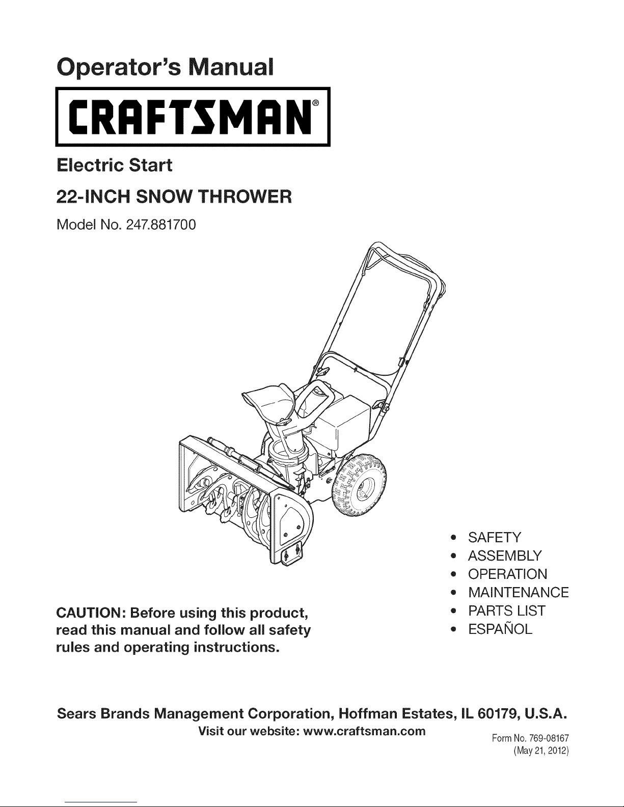
Electric Start
-INCH SNOW THROWER
Model No. 247.881700
CAUTION: Before using this product,
read this manual and follow all safety
rules and operating instructions.
Sears Brands Management Corporation, Hoffman Estates, IL 60179, U.S.A.
Visit our website: www.craftsman.corn
,, SAFETY
o ASSEMBLY
OPERATION
MAINTENANCE
PARTS LIST
o ESPANOL
FormNo.769-08167
(May21,2012)
Page 2
WarrantyStatement.................... Page2
SafeOperation Practices ................ Page 3
Assembly ............................ Page 7
Operation ........................... Page 11
Maintenance & Service ................. Page 15
Off-Season Storage ................... Page 20
Troubleshooting ...................... Page 21
Parts List ............................ Page 22
Repair Protection Agreement ............ Page 43
Espa_ol ............................. Page 44
Contact Numbers .................. Back Cover
CRAFTSMANTWOYEAR FULLWARRANTY
FORTWOYEARSfromthe dateof purchase,this productiswarrantedagainstanydefectsin materialor workmanship.A defective
productwillreceivefreerepairor replacementif repairisunavailable.
Forwarranty coverage details to obtain freerepairorreplacement,visittheweb site: www.craftsman.com
Thiswarranty coversONLYdefects in materialandworkmanship. Warrantycoverage does NOTinclude:
• Expendableitemsthatcanwearoutfromnormalusewithinthewarrantyperiod,includingbutnot limitedtoaugers,augerpaddles,
driftcutters,skidshoes,shaveplate,shearpins,sparkplug,aircleaner,belts,andoilfilter.
• Standardmaintenanceservicing,oilchanges,or tune-ups.
Tirereplacementor repaircausedbypuncturesfromoutsideobjects,suchasnails,thorns,stumps,or glass.
Tireor wheelreplacementorrepairresultingfromnormalwear,accident,or improperoperationormaintenance.
Repairsnecessarybecauseof operatorabuse,includingbutnotlimitedto damagecausedbyover-speedingtheengine,or from
impactingobjectsthatbendtheframe,augershaft,etc.
• Repairsnecessarybecauseof operatornegligence,includingbutnot limitedto,electricalandmechanicaldamagecausedby
improperstorage,failureto usethepropergradeandamountof engineoil,or failureto maintaintheequipmentaccordingtothe
instructionscontainedintheoperator'smanual.
• Engine(fuelsystem)cleaningorrepairscausedbyfueldeterminedto becontaminatedoroxidized(stale).Ingeneral,fuelshouldbe
usedwithin30 daysof itspurchasedate.
Normaldeteriorationandwearof theexteriorfinishes,orproductlabelreplacement.
Thiswarrantyisvoidif thisproductisever usedwhileprovidingcommercialservicesor if rentedtoanotherperson.
Thiswarrantygivesyouspecificlegalrights,andyou mayalsohaveotherrightswhichvaryfromstatetostate.
SearsBrands ManagementCorporation, HoffmanEstates,IL 60179
EngineOilType: 5W-30
EngineOilCapacity: 20ounces
FuelCapacity: 2.3Quarts
SparkPlug: F6RTC(F6TC)
SparkPlugGap: .020"to.030"
© SearsBrands,LLC
ModelNumber.................................................................
Serial Number .................................................................
Dateof Purchase.............................................................
Recordthemodelnumber,serialnumber
anddateof purchaseabove
2
Page 3
Thissymbolpointsout importantsafetyinstructionswhich,if not
followed,couldendangerthepersonalsafetyand/orpropertyof
yourselfandothers. Readandfollowall instructionsin thismanual
beforeattemptingto operatethismachine.Failuretocomplywith
theseinstructionsmayresultin personalinjury.Whenyou seethis
symbol,HEEDITSWARNING!
Thismachinewasbuiltto beoperatedaccordingtothesafeopera-
tionpracticesinthis manual.Aswithanytypeof powerequipment,
carelessnessorerroron the partoftheoperatorcan resultin serious
injury.Thismachineiscapableofamputatingfingers,hands,toes
andfeetandthrowingdebris.Failuretoobservethefollowingsafety
instructionscouldresultin seriousinjuryor death.
CALIFORNIA PROPOSITION 65
EngineExhaust,someof itsconstituents,andcertainvehicle
componentscontainoremitchemicalsknowntoStateofCalifornia
tocausecancerandbirthdefectsorotherreproductiveharm,
TRAiNiNG
• Read,understand,andfollowall instructionson the machineand
in themanual(s)beforeattemptingtoassembleandoperate.
Failuretodo socan resultinseriousinjurytotheoperatorand/
orbystanders.Keepthismanualin a safeplaceforfutureand
regularreferenceandfororderingreplacementparts.
• Befamiliarwithall controlsandtheirproperoperation.Knowhow
tostopthe machineanddisengagethemquickly.
• Neverallowchildrenunder14yearsof agetooperatethis
machine.Children14andovershouldreadandunderstandthe
instructionsandsafeoperationpracticesin thismanualandon
themachineandbe trainedandsupervisedbyanadult.
Neverallowadultsto operatethismachinewithoutproper
instruction.
• Thrownobjectscancauseseriouspersonalinjury.Planyour
snow-throwingpatterntoavoiddischargeof materialtoward
roads,bystandersandthelike.
Keepbystanders,petsandchildrenat least75feetfromthe
machinewhileitis in operation.Stopmachineifanyoneenters
thearea.
• Exercisecautiontoavoidslippingorfalling,especiallywhen
operatinginreverse.
Your Responsibility--Restrict theuseofthispowermachineto
personswhoread,understandandfollowthewarningsandinstruc-
tionsin thismanualandon themachine.
SAVE THESE INSTRUCTIONS!
PREPARATION
Thoroughlyinspecttheareawheretheequipmentistobeused.
Removeall doormats,newspapers,sleds,boards,wiresandother
foreignobjects,whichcouldbe trippedoverorthrownbythe auger/
impeller.
• Alwayswearsafetyglassesor eyeshieldsduringoperationand
whileperformingan adjustmentor repairto protectyoureyes.
Thrownobjectswhichricochetcancauseseriousinjurytothe
eyes.
Donot operatewithoutwearingadequatewinteroutergarments.
Donot wearjewelry,longscarvesorotherlooseclothing,which
couldbecomeentangledin movingparts.Wearfootwearwhich
willimprovefootingonslipperysurfaces.
Usea groundedthree-wireextensioncordandreceptaclefor all
machineswithelectricstartengines.
Disengageall controlleversbeforestartingtheengine.
Adjustcollectorhousingheighttocleargravelorcrushedrock
surfaces.
• Neverattempttomakeanyadjustmentswhileengineis running,
exceptwherespecificallyrecommendedintheoperator'smanual.
Letengineandmachineadjustto outdoortemperaturebefore
startingtoclearsnow.
3
Page 4
SafeHandling of Gasoline
Toavoidpersonalinjuryor propertydamageuseextremecarein
handlinggasoline.Gasolineisextremelyflammableandthevaporsare
explosive.Seriouspersonalinjurycanoccurwhengasolineis spilled
onyourselforyourclotheswhichcan ignite. Washyourskinand
changeclothesimmediately.
• Useonlyan approvedgasolinecontainer.
• Extinguishallcigarettes,cigars,pipesandother sourcesof
ignition.
• Neverfuel machineindoors.
• Neverremovegascapor addfuel whiletheengineishotor
running.
• Allowenginetocoolat leasttwo minutesbeforerefueling.
• Neveroverfillfueltank.Fill tankto nomorethan1/2inchbelow
bottomoffillerneckto providespaceforfuelexpansion.
• Replacegasolinecapandtightensecurely.
• Ifgasolineisspilled,wipe itoff theengineandequipment.Move
machinetoanotherarea.Wait5minutesbeforestartingthe
engine.
• Neverstorethe machineorfuelcontainerinsidewherethereisan
openflame,sparkor pilotlight(e.g.furnace,waterheater,space
heater,clothesdryeretc.).
• Allowmachinetocoolatleast5 minutesbeforestoring.
• Neverfill containersinsidea vehicleor ona truckor trailerbed
witha plasticliner.Alwaysplacecontainersonthe groundaway
fromyourvehiclebeforefilling.
• If possible,removegas-poweredequipmentfromthetruckor
trailerandrefuelitonthe ground.Ifthis isnotpossible,thenrefuel
suchequipmenton a trailerwithaportablecontainer,ratherthan
froma gasolinedispensernozzle.
• Keepthe nozzlein contactwiththerimofthefuel tankor
containeropeningatalltimesuntilfuelingiscomplete.Donotuse
a nozzlelock-opendevice.
OPERATION
• Do notputhandsorfeetnear rotatingparts,in theauger/impeller
housingorchuteassembly.Contactwiththerotatingpartscan
amputatehandsandfeet.
• Theauger/impellercontrolleveris a safetydevice.Neverbypass
itsoperation.Doingsomakesthe machineunsafeandmaycause
personalinjury.
• Thecontrolleversmustoperateeasilyin bothdirectionsand
automaticallyreturntothe disengagedpositionwhenreleased.
• Neveroperatewitha missingordamagedchuteassembly.Keep
all safetydevicesinplaceandworking.
• Neverrunanengineindoorsor ina poorlyventilatedarea.Engine
exhaustcontainscarbonmonoxide,anodorlessanddeadlygas.
• Do notoperatemachinewhileundertheinfluenceofalcoholor
drugs.
• Mufflerandenginebecomehotandcan causea burn.Do not
touch.Keepchildrenaway.
• Exerciseextremecautionwhenoperatingon orcrossinggravel
surfaces.Stayalertforhiddenhazardsortraffic.
Exercisecautionwhenchangingdirectionandwhileoperatingon
slopes.Do notoperateon steepslopes.
Planyoursnow-throwingpatternto avoiddischargetowards
windows,walls,carsetc.Thus,avoidingpossibleproperty
damageorpersonalinjurycausedby a ricochet.
Neverdirectdischargeat children,bystandersand petsor allow
anyoneinfrontof themachine.
Donot overloadmachinecapacityby attemptingto clearsnowat
toofastof a rate.
Neveroperatethismachinewithoutgoodvisibilityorlight.Always
be sureof yourfootingandkeepa firmholdon thehandles.Walk,
neverrun.
Disengagepowerto theauger/impellerwhentransportingor not
in use.
Neveroperatemachineathightransportspeedson slippery
surfaces.Lookdownand behindandusecarewhenbackingup.
Ifthemachineshouldstartto vibrateabnormally,stopthe engine,
disconnectthesparkplugwireandgrounditagainsttheengine.
Inspectthoroughlyfor damage.Repairanydamagebefore
startingandoperating.
Disengageall controlleversandstopenginebeforeyouleave
theoperatingposition(behindthehandles).Waituntiltheauger/
impellercomestoa completestopbeforeuncloggingthechute
assembly,makingany adjustments,or inspections.
Neverputyourhandinthedischargeor collectoropenings.Do
notunclogchuteassemblywhileengineis running.Shutoff
engineand remainbehindhandlesuntilall movingpartshave
stoppedbeforeunclogging.
Useonlyattachmentsandaccessoriesapprovedbythemanufac-
turer(e.g.wheelweights,tirechains,cabsetc.). Forinformation
concerningtheseitems,call1-800-469-4663.
Whenstartingengine,pullcord slowlyuntilresistanceisfelt,then
pull rapidly.Rapidretractionofstartercord(kickback)willpull
handandarmtowardenginefasterthanyoucanlet go.Broken
bones,fractures,bruisesorsprainscouldresult.
Ifsituationsoccurwhichare notcoveredinthismanual,usecare
andgoodjudgment.
Toorderpartsor scheduleserviceforthisproduct,call 1-800-
469-4663.
CLEARING A CLOGGED DISCHARGE CHUTE
Handcontactwiththe rotatingimpellerinsidethedischargechute
is the mostcommoncauseofinjuryassociatedwithsnowthrowers.
Neveruseyourhandtocleanout thedischargechute.
Toclear thechute:
1. SHUTTHEENGINEOFF!
2. Wait 10secondstobe suretheimpellerbladeshavestopped
rotating.
3. Alwaysusea clean-outtool,not yourhands.
4
Page 5
MAINTENANCE & STORAGE
• Nevertamperwithsafetydevices.Checktheirproperoperation
regularly.Refertothemaintenanceandadjustmentsectionsof
thismanual.
• Beforecleaning,repairing,or inspectingmachinedisengageall
controlleversandstoptheengine.Waituntilthe auger/impeller
cometoa completestop.Disconnectthe sparkplugwireand
groundagainsttheengineto preventunintendedstarting.
Checkboltsand screwsforpropertightnessatfrequentintervals
tokeepthemachineinsafeworkingcondition.Also,visually
inspectmachineforanydamage.
Donotchangetheenginegovernorsettingor over-speedthe
engine.Thegovernorcontrolsthe maximumsafeoperatingspeed
ofthe engine.
Snowthrowershaveplatesandskidshoesaresubjecttowear
anddamage.Foryoursafetyprotection,frequentlycheckall
componentsand replacewithoriginalequipmentmanufacturer's
(OEM)partsonlyaslistedinthe Partspagesof thisoperator's
manual.Useofpartswhichdonot meettheoriginalequipment
specificationsmayleadto improperperformanceandcompro-
misesafety!
Checkcontrolleversperiodicallytoverifytheyengageanddisen-
gageproperlyandadjust,ifnecessary.Refertotheadjustment
sectioninthisoperator'smanualfor instructions.
Maintainor replacesafetyandinstructionlabels,asnecessary.
Observeproperdisposallawsand regulationsforgas,oil,etc.to
protecttheenvironment.
Priorto storing,runmachinea few minutestoclear snowfrom
machineand preventfreezeupofauger/impeller.
Neverstorethemachineorfuel containerinsidewherethereisan
openflame,sparkorpilot lightsuchas a waterheater,furnace,
clothesdryeretc.
Alwaysrefertothe operator'smanualforproperinstructionson
off-seasonstorage.
Checkfuelline,tank, cap,andfittingsfrequentlyfor cracksor
leaks.Replaceif necessary.
Donotcrankenginewithsparkplugremoved.
AccordingtotheConsumerProductsSafetyCommission(CPSC)
andtheU.S.EnvironmentalProtectionAgency(EPA),thisproduct
hasan AverageUsefulLifeof seven(7)years,or 60 hoursof
operation.AttheendoftheAverageUsefulLifehavethe machine
inspectedannuallybyanauthorizedservicedealerto ensurethat
allmechanicalandsafetysystemsareworkingproperlyand not
wornexcessively.Failuretodo socanresultinaccidents,injuries
ordeath.
DO NOT MODIFY ENGINE
Toavoidseriousinjuryor death,do notmodifyengineinany way.
Tamperingwiththegovernorsettingcanleadtoa runawayengineand
causeitto operateat unsafespeeds.Nevertamperwithfactorysetting
ofenginegovernor.
NOTICE REGARDING EMiSSiONS
EngineswhicharecertifiedtocomplywithCaliforniaandfederal
EPAemissionregulationsforSORE(SmallOff RoadEquipment)are
certifiedto operateonregularunleadedgasoline,and mayinclude
thefollowingemissioncontrolsystems:EngineModification(EM),
OxidizingCatalyst(OC),SecondaryAirInjection(SAI)and ThreeWay
Catalyst(TWO)if soequipped.
SPARK ARRESTOR
Thismachineisequippedwithaninternalcombustionengineand
shouldnotbe usedonor nearanyunimprovedforest-covered,
brush-coveredorgrass-coveredlandunlessthe engine'sexhaust
systemisequippedwitha sparkarrestormeetingapplicablelocalor
statelaws(if any)
Ifa sparkarrestorisused,it shouldbemaintainedineffectiveworking
orderbytheoperator.Inthe StateofCaliforniatheaboveis required
bylaw (Section4442ofthe CaliforniaPublicResourcesCode).Other
statesmayhavesimilarlaws. Federallawsapplyonfederallands.
A sparkarrestorfor themufflerisavailablethroughyournearestSears
PartsandRepairServiceCenter.
Page 6
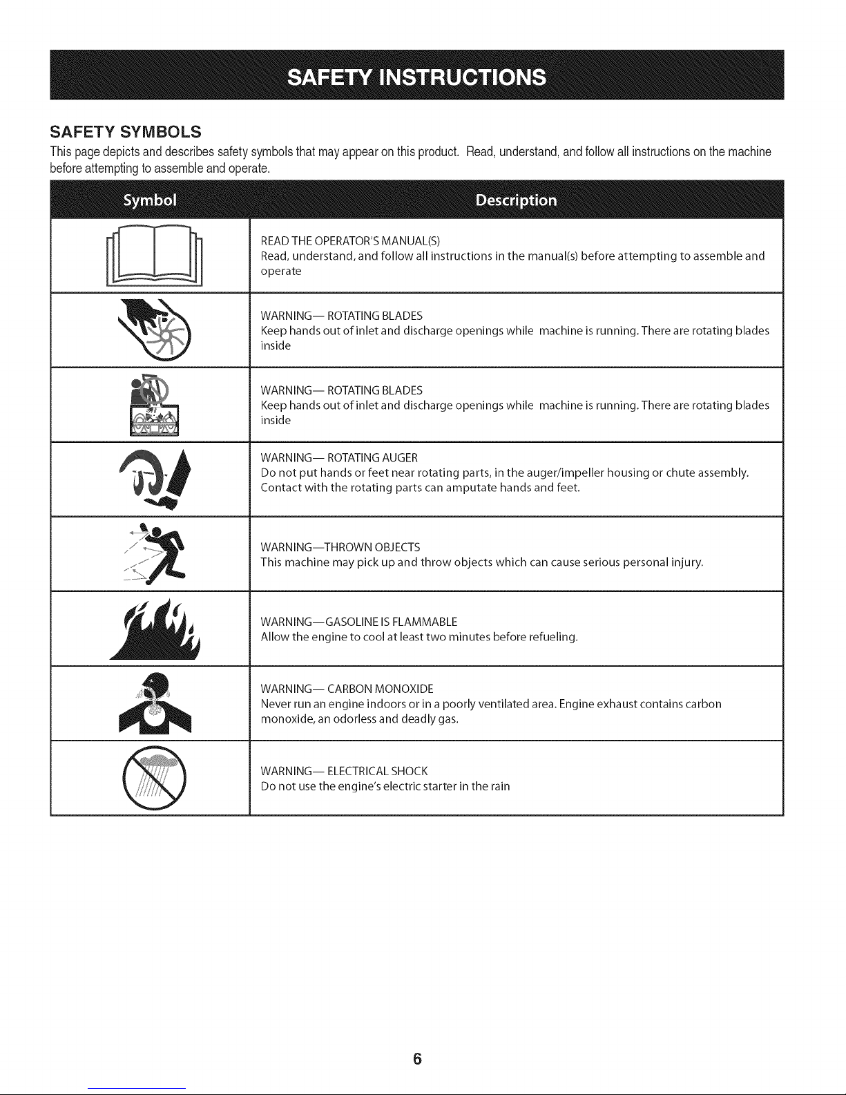
SAFETY SYMBOLS
Thispagedepictsanddescribessafetysymbolsthatmayappearonthisproduct. Read,understand,andfollowall instructionson themachine
beforeattemptingto assembleandoperate.
READ THE OPERATOR'S MANUAL(S)
i
. +
i
Read, understand, and follow all instructions in the manual(s) before attempting to assemble and
operate
WARNING-- ROTATING BLADES
Keep hands out of inlet and discharge openings while machine is running. There are rotating blades
inside
WARNING-- ROTATING BLADES
Keep hands out of inlet and discharge openings while machine is running. There are rotating blades
inside
WARNING-- ROTATING AUGER
Do not put hands or feet near rotating parts, in the auger/impeller housing or chute assembly.
Contact with the rotating parts can amputate hands and feet.
"JIp
WARNING--THROWN OBJECTS
This machine may pick up and throw objects which can cause serious personal injury.
WARNING--GASOLINE IS FLAMMABLE
Allow the engine to cool at least two minutes before refueling.
WARNING-- CARBON MONOXIDE
Never run an engine indoors or in a poorly ventilated area. Engine exhaust contains carbon
monoxide, an odorless and deadly gas+
WARNING-- ELECTRICAL SHOCK
Do not use the engine's electric starter in the rain
6
Page 7
iMPORTANT:Thisunitis shippedwiththeenginefullofoil. After
assembly,see page10forfuel andoildetails.
Removing From Carton
1. Cutthe cornersofthecartonandlaythe sidesflaton theground.
Removeall packinginserts.
2. Movethe snowthroweroutof thecarton.
3. Makecertainthe cartonhasbeencompletelyemptiedbefore
discardingit.
DO NOTliftthe snowthrower bythechute handle.
Before Assembly
NOTE:Referenceto right,left, frontor rearoftheunit isfromthe
operatingposition,facingforward,unlessotherwisestated.
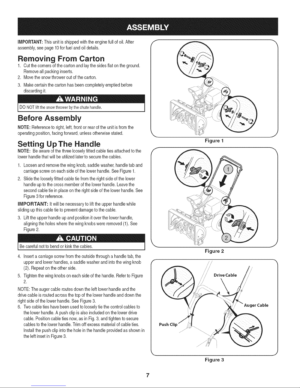
Setting Up The Handle
NOTE: Beawareofthe threelooselyfittedcabletiesattachedtothe
lowerhandlethatwill beutilizedlatertosecurethecables.
1. Loosenand removethewingknob,saddlewasher,handletaband
carriagescrewoneachsideofthe lowerhandle.SeeFigure1.
2. Slidethe looselyfittedcabletie fromtherightsideofthe lower
handleupto thecrossmemberofthelowerhandle.Leavethe
secondcabletie inplaceonthe rightsideofthe lowerhandle.See
Figure3for reference.
iMPORTANT: itwillbenecessaryto lifttheupperhandlewhile
slidingupthiscabletieto preventdamagetothecable.
3. Liftthe upperhandleupandpositionit overthelowerhandle,
aligningthe holeswherethewingknobswereremoved(1).See
Figure2.
Figure 1
Becarefulnotto bendor kinkthecables.
4. Inserta carriagescrewfromtheoutsidethrougha handletab,the
upperand lowerhandles,asaddlewasherandintothe wingknob
(2). Repeatonthe otherside.
5. Tightenthewingknobsoneach sideof thehandle.RefertoFigure
2.
NOTE:Theaugercableroutesdowntheleft lowerhandleandthe
drivecableisroutedacrossthetopof thelowerhandleanddownthe
rightside ofthe lowerhandle.SeeFigure3.
6. Twocabletieshavebeenusedtolooselytie thecontrolcablesto
thelowerhandle.Apushclipis alsoincludedon thelowerdrive
cable.Positioncabletiesnow,as inFig.3,andtightento secure
cablestothe lowerhandle.Trimoff excessmaterialof cableties.
Installthe pushclip intotheholeinthe handleprovidedasshownin
theleftinsetinFigure3.
Figure 2
Drive Cable
/
Auger Cable
Push Cli
Figure 3
7
Page 8
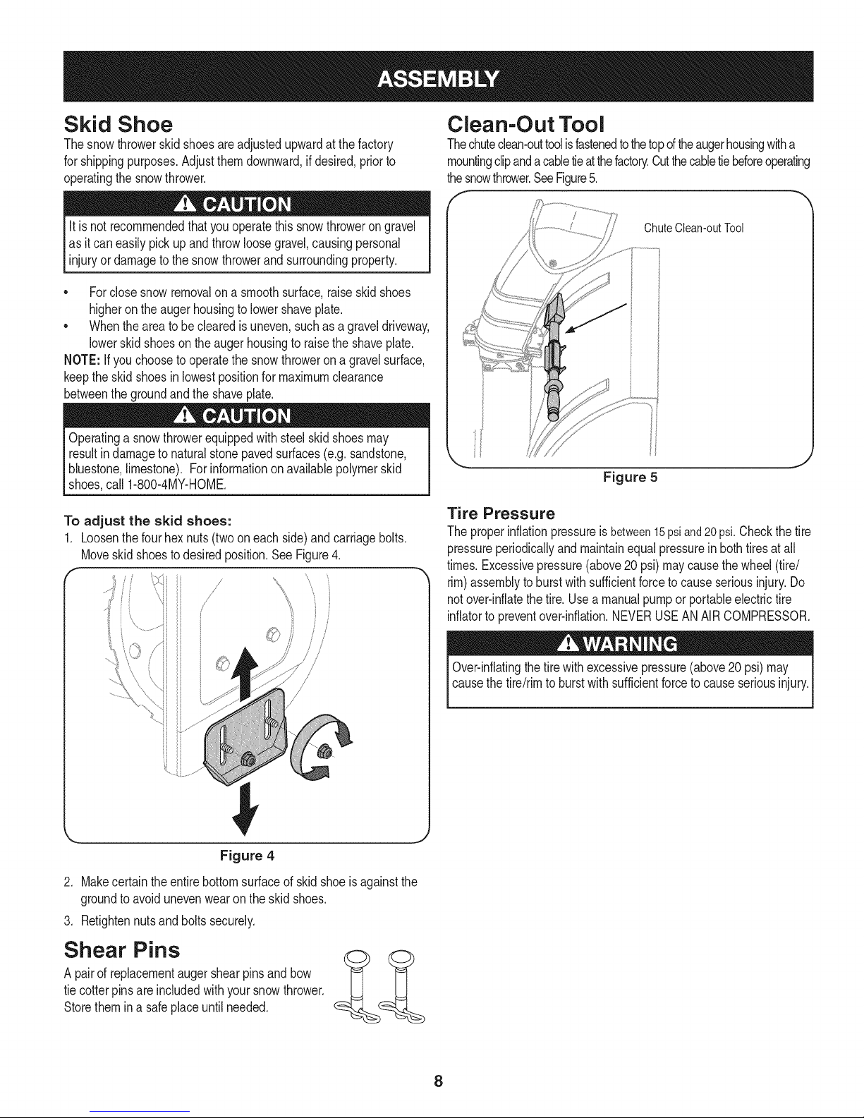
Skid Shoe
Thesnowthrowerskidshoesareadjustedupwardat thefactory
forshippingpurposes.Adjustthemdownward,ifdesired,priorto
operatingthesnowthrower.
Clean-Out Tool
Thechuteclean-outtoolisfastenedtothetopoftheaugerhousingwitha
mountingclipandacabletieatthefactory.Cutthecabletiebeforeoperating
thesnowthrower.SeeFigure5.
It isnot recommendedthatyouoperatethissnowthrowerongravel
as itcaneasilypickup andthrowloosegravel,causingpersonal
injuryordamagetothe snowthrowerand surroundingproperty.
• Forclosesnowremovalona smoothsurface,raiseskidshoes
higherontheaugerhousingtolowershaveplate.
• Whentheareato beclearedis uneven,suchasagraveldriveway,
lowerskidshoeson theaugerhousingtoraisethe shaveplate.
NOTE:Ifyou choosetooperatethesnowthrowerona gravelsurface,
keepthe skidshoesin lowestpositionformaximumclearance
betweenthegroundandtheshaveplate.
Operatingasnowthrowerequippedwithsteelskidshoesmay
resultindamageto naturalstonepavedsurfaces(e.g.sandstone,
bluestone,limestone).For informationonavailablepolymerskid
shoes,call 1-800-4MY-HOME.
To adjust the skid shoes:
1. Loosenthefourhexnuts(twooneach side)andcarriagebolts.
Moveskidshoestodesiredposition.SeeFigure4.
/
/
//
0! i
ChuteClean-outTool
Figure 5
Tire Pressure
Theproperinflationpressureisbetween15psiand20psi.Checkthe tire
pressureperiodicallyandmaintainequalpressureinbothtiresatall
times.Excessivepressure(above20 psi)maycausethe wheel(tire/
rim)assemblytoburstwithsufficientforceto causeseriousinjury.Do
notover-inflatethetire.Usea manualpumpor portableelectrictire
inflatorto preventover-inflation.NEVERUSEANAIRCOMPRESSOR.
Figure 4
2. Makecertaintheentirebottomsurfaceof skidshoeisagainstthe
groundtoavoidunevenwearontheskidshoes.
3. Retightennutsandboltssecurely.
Shear Pins
A pairof replacementaugershearpinsandbow
tiecotterpinsare includedwithyoursnowthrower.
Storethemina safeplaceuntilneeded.
Over-inflatingthe tirewithexcessivepressure(above20psi)may
causethetire/rimto burstwithsufficientforcetocauseseriousinjury.
8
Page 9

Fuel Recommendations
Useautomotivegasoline(unleadedor low leadedtominimizecombus-
tionchamberdeposits)witha minimumof87octane.Gasolinewith
upto 10%ethanolor 15%MTBE(MethylTertiaryButylEther)canbe
used.Neveruseanoil/gasolinemixtureor dirtygasoline.Avoidgetting
dirt,dust,or waterinthefueltank. DONOTuseE85gasoline.
* Refuelin awell-ventilatedareawiththeenginestopped.Donot
smokeorallowflamesorsparksintheareawheretheengineis
refueledorwheregasolineisstored.
* Donotoverfillthefuel tank.Afterrefueling,makesurethe tank
capis closedproperlyandsecurely.
* Becarefulnotto spillfuelwhenrefueling.Spilledfuelor fuelvapor
mayignite.Ifany fuelisspilled,makesurethe areaisdrybefore
startingtheengine.
* Avoidrepeatedor prolongedcontactwithskinor breathingof
vapor.
Adding Fuel
Useextremecarewhenhandlinggasoline.Gasolineisextremely
flammableandthe vaporsareexplosive.Neverfuelthe machine
indoorsorwhiletheengineishotor running.Extinguishcigarettes,
cigars,pipesandothersourcesofignition.
Checking Oil Level
Theengineis shippedwithoil intheengine.Youmust,however,
checkthe oil levelpriortooperatingthesnowthrower.Runningthe
enginewithinsufficientoilcancauseseriousenginedamageand
voidtheenginewarranty.
NOTE: Besuretocheckthe engineon a levelsurfacewiththe engine
stopped.
1. Removetheoil fillercap/dipstickand wipethe dipstickclean.See
Figure7.
f-
Alwayskeephandsandfeetclear ofequipmentmovingparts.Donot
usea pressurizedstartingfluid.Vaporsareflammable.
1. Cleanaroundfuel fillbeforeremovingcaptofuel.
2. Afuellevelindicatoris locatedinthefuel tank.Filltankuntil fuel
reachesthefuellevel indictor,Figure6. Becarefulnottooverfill.
FuelLevelIndicator
TopView
)
_,., J
Figure7
2. Insertthe cap/dipstickintotheoilfillerneck,turnthecap 1/4turnuntil
fully seated.
NOTE:On someengines,a threadedcap/dipstickmayexist insteadof
a 1/4turncap asdescribedabove.Inthisinstancedo notfullytighten
the captochecktheoil level.Simplyrestthe capon the threadsto
checkfor properoil level.
3. Removetheoil fillercap/dipstick.Ifthe levelis low,slowlyadd oiluntil
oil levelregistersbetweenhigh(H) andlow(L), Figure7. Referto the
EngineMaintenancesectionfor correctoil viscosityandengineoil
capacity.
NOTE:Do notoverfill.Overfillingwithoil mayresultinenginesmoking,
hardstartingorsparkplugfouling.
4. Replaceandtightencap/dipstickfirmly beforestartingengine.
Figure6
9
Page 10
Discharge Chute
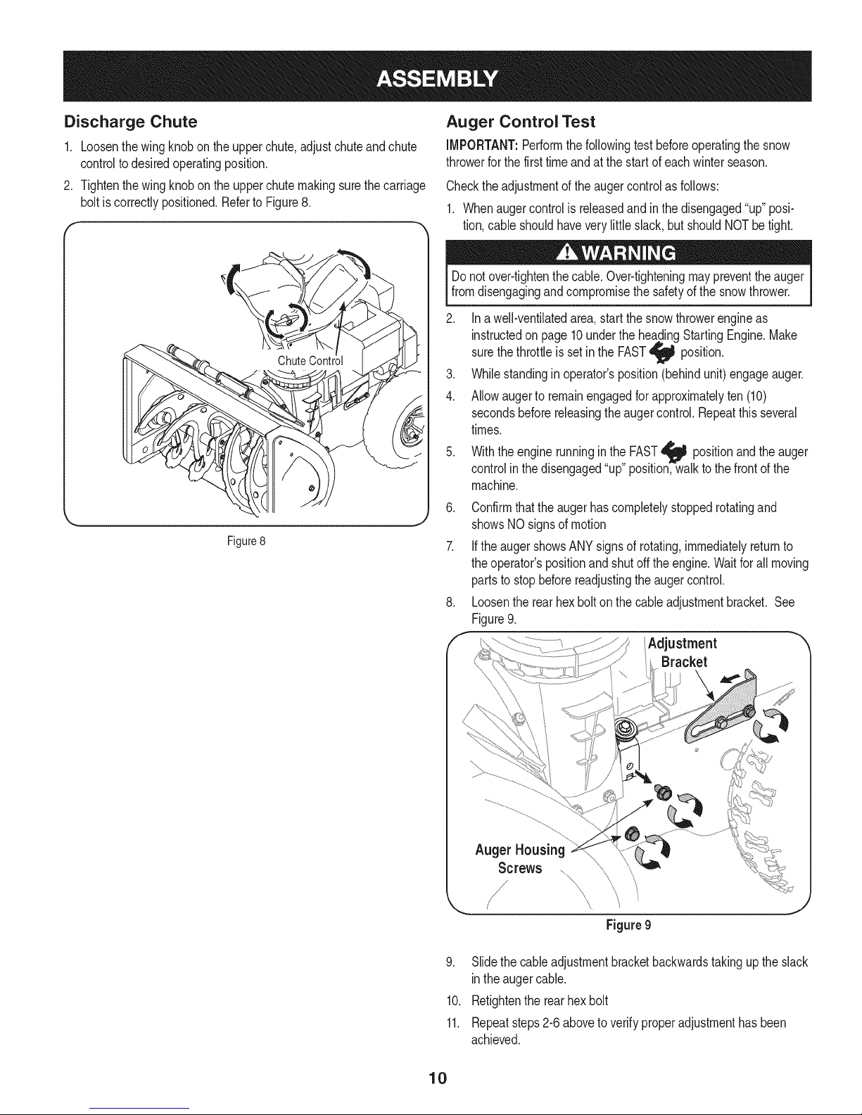
1. Loosenthewingknobon the upperchute,adjustchuteand chute
controltodesiredoperatingposition.
2. Tightenthewingknobontheupperchutemakingsurethecarriage
boltiscorrectlypositioned.Referto Figure8.
J
Figure8
Auger Control Test
iMPORTANT:Performthefollowingtestbeforeoperatingthesnow
throwerforthe firsttimeandat thestartof eachwinterseason.
Checktheadjustmentof theaugercontrolasfollows:
1. Whenaugercontrolisreleasedandinthedisengaged"up"posi-
tion,cableshouldhaveverylittleslack,butshouldNOTbetight.
Donot over-tightenthe cable.Over-tighteningmaypreventtheauger
fromdisengagingandcompromisethe safetyofthe snowthrower.
2. Ina well-ventilatedarea,startthesnowthrowerengineas
instructedon page10undertheheadingStartingEngine.Make
sure
thethrottleisset inthe FAST
3. Whilestandinginoperator'sposition(behindunit)engageauger.
4. Allowaugerto remainengagedforapproximatelyten(10)
secondsbeforereleasingthe augercontrol.Repeatthisseveral
times.
5. Withtheenginerunninginthe FAST_ positionand the
controlinthedisengaged"up"position,walktothefrontof the
machine.
6. Confirmthattheaugerhascompletelystoppedrotatingand
showsNOsignsofmotion
7. iftheaugershowsANYsignsof rotating,immediatelyreturnto
theoperator'spositionandshutofftheengine.Waitforallmoving
partsto stopbeforereadjustingtheaugercontrol.
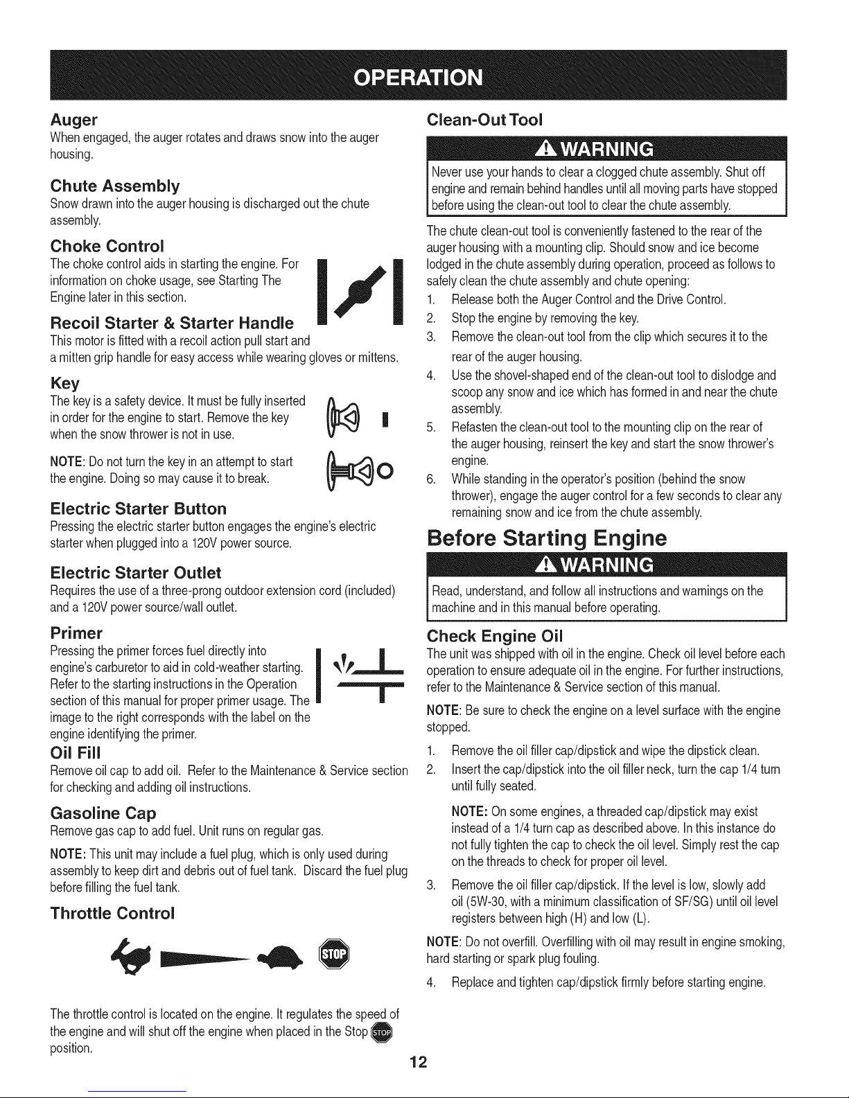
8. Loosentherearhexbolton thecableadjustmentbracket.See
Figure9.
f Adjustment "
position.
auger
Bracket
Auger Housing
Screws
Figure9
9. Slidethecableadjustmentbracketbackwardstakingup the slack
intheaugercable.
10. Retightentherearhexbolt
11. Repeatsteps2-6aboveto verifyproperadjustmenthasbeen
achieved.
10
Page 11

UpperChute
Upper Handle
Drive
AugerControl Control
ChuteAssembl
Clean-out Tool
Auger
ShavePlate
ChuteKnob
_- Skid Shoe
FuelCap
RecoilStarter
Handle
Oil Drain Electric StarterOutlet
Befamiliarwithallthecontrolson thesnowthrowerandtheir properoperation.Knowhowto stopthemachineanddisengagethemquickly.
Snowthrowercontrolsandfeaturesaredescribedbelowandillustrated
in thefigureabove.
Drive Control
Locatedon theundersideof theupperhandle,thedrivecontrolis used
toengage/disengagewheels.Squeezethe drivecontrolagainstthe
upperhandletoengagethe wheels;releasetodisengage.
Auger Control
Theaugercontrolis on thefronttheupperhandle.Squeezethe auger
controlagainsttheupperhandleto engagetheauger;releaseto
disengagethe auger.
Chute Handle
Thedirectionof snowthrowingcorrespondstothedirectionofthe
chuteopening.Usethechutehandletoturn thechuteassemblyinthe
directionyouwishto throwthesnow.
Chute Knob
Thedistancesnowisthrowncanbe adjustedbyeitherraisingor
loweringtheupperchute.Loosenthechuteknobonthe sideof the
upperchutetoadjust.Pivottheupperchutetodesiredposition,and
retightenthechuteknob.Raisingthechutethrowsthe snowfurther.
Shave Plate
Theshaveplatemaintainscontactwithpavementasthesnow
throwerispropelled,allowingsnowcloseto pavement'ssurfacetobe
Nevermakeadjustmentstothechuteassemblyunlessbothaugerand
drivecontrolsaredisengagedandtheoperatorisstandingbesidetheunit.
IMPORTANT:Referto AugerControlTestinthe Assemblysectionof
thismanualpriorto operatingyoursnowthrower.Readandfollowall
instructionscarefullyandperformall adjustmentsto verifyyoursnow
throwerisoperatingsafelyandproperly.
discharged.
Skid Shoe
Thespacebetweenthe shaveplateandthegroundcanbe adjusted.
Forclosesnowremoval,placeskidshoesin the highestposition.Use
middleorlowestpositionwhenareato beclearedis unevenoron
gravelsurfaces.
11
Page 12
Auger
Whenengaged,theaugerrotatesanddrawssnowintotheauger
housing.
Chute Assembly
Snowdrawnintothe augerhousingisdischargedoutthechute
assembly.
Choke Control
Thechokecontrolaidsinstartingtheengine.For
informationonchokeusage,seeStartingThe
Enginelaterinthis section.
I j _ lodgedinthe chuteassemblyduringoperation,proceedasfollowsto
Recoil Starter & Starter Handle
Thismotorisfittedwitha recoilactionpullstart and
a mittengriphandlefor easyaccesswhilewearingglovesor mittens.
Key
Thekeyis a safetydevice.Itmustbefully inserted
inorderforthe enginetostart.Removethe key
whenthe snowthrowerisnot in use.
NOTE:Do notturn thekeyinanattemptto start
theengine.Doingso maycauseitto break.
(_ assembly.
| 5. Refastentheclean-outtooltothe mountingclipon therearof
0 6. Whilestandingintheoperator'sposition(behindthe snow
Electric Starter Button
Pressingtheelectricstarterbuttonengagestheengine'selectric
starterwhenpluggedintoa 120Vpowersource.
Clean=Out Tool
Neveruseyour handstoclearacloggedchuteassembly.Shutoff
engineandremainbehindhandlesuntilall movingpartshavestopped
beforeusingtheclean-outtooltoclear thechuteassembly.
Thechuteclean-outtool isconvenientlyfastenedtothe rearofthe
augerhousingwitha mountingclip.Shouldsnowandice become
safelycleanthechuteassemblyandchuteopening:
1. ReleaseboththeAugerControlandthe DriveControl.
I
2. Stopthe enginebyremovingthekey.
3. Removetheclean-outtoolfromtheclip whichsecuresittothe
rearofthe augerhousing.
4. Usetheshovel-shapedendoftheclean-outtooltodislodgeand
scoopanysnowandice whichhasformedinand nearthechute
theaugerhousing,reinsertthekeyandstartthe snowthrower's
engine.
thrower),engagetheaugercontrolfora fewsecondstoclearany
remainingsnowand icefromthechuteassembly.
Before Starting Engine
Electric Starter Outlet
Requirestheuseofa three-prongoutdoorextensioncord(included)
anda 120Vpowersource/walloutlet.
Primer
Pressingtheprimerforcesfueldirectlyinto
engine'scarburetortoaid incold-weatherstarting.
Refertothe startinginstructionsinthe Operation
sectionofthis manualforproperprimerusage.The
imageto therightcorrespondswiththe labelon the
engineidentifyingtheprimer.
Oil Fill
Removeoil cap toaddoil. RefertotheMaintenance& Servicesection
forcheckingandaddingoil instructions.
Gasoline Cap
Removegas capto addfuel.Unitrunsonregulargas.
NOTE:Thisunit mayincludeafuel plug,whichisonlyusedduring
assemblytokeepdirtanddebrisout offuel tank. Discardthefuelplug
beforefillingthefuel tank.
Throttle Control
Read,understand,andfollowall instructionsand warningsonthe
machineandinthis manualbeforeoperating.
Check Engine Oil
Theunitwasshippedwithoilin the engine.Checkoil levelbeforeeach
operationtoensureadequateoil intheengine.Forfurtherinstructions,
refertothe Maintenance& Servicesectionofthis manual.
NOTE:Besuretochecktheengineona levelsurfacewiththeengine
stopped.
1. Removetheoilfiller cap/dipstickandwipethedipstickclean.
2. Insertthecap/dipstickintotheoil fillerneck,turnthecap 1/4turn
untilfullyseated.
NOTE:Onsomeengines,athreadedcap/dipstickmayexist
insteadofa 1/4turncap asdescribedabove.Inthis instancedo
notfullytightenthe captocheckthe oil level.Simplyrestthecap
on thethreadsto checkfor properoil level.
.
Removethe oilfillercap/dipstick.If thelevelis low,slowlyadd
oil (5W-30,witha minimumclassificationofSF/SG)untiloil level
registersbetweenhigh(H) andlow(L).
NOTE:Donotoverfill.Overfillingwithoil mayresultinenginesmoking,
hardstartingor sparkplugfouling.
4. Replaceandtightencap/dipstickfirmlybeforestartingengine.
Thethrottlecontrolis locatedontheengine.It regulatesthe speedof
theengineandwill shutoff theenginewhenplacedintheStop0
position.
12
Page 13
Gasoline
Useautomotivegasoline(unleadedor low leadedtominimizecombus-
tionchamberdeposits)witha minimumof87octane.Gasolinewith
upto 10%ethanolor 15%MTBE(MethylTertiaryButylEther)canbe
used.Neveruseanoil/gasolinemixtureordirtygasoline.Avoidgetting
dirt,dust,or waterinthe fueltank.DONOTuseE85gasoline.
• Refuelina well-ventilatedareawiththe enginestopped.Donot
smokeorallowflamesorsparksintheareawheretheengineis
refueledorwheregasolineisstored.
• Do notoverfillthe fueltank.Afterrefueling,makesurethetank
capis closedproperlyandsecurely.
• Becarefulnot tospill fuelwhenrefueling.Spilledfuelor fuelvapor
mayignite.Ifanyfuel isspilled,makesuretheareaisdrybefore
startingtheengine.
• Avoidrepeatedor prolongedcontactwithskinor breathingof
vapor.
Useextremecarewhenhandlinggasoline.Gasolineisextremely
flammableandthe vaporsareexplosive.Neverfuelthemachine
indoorsorwhiletheengineishotor running.Extinguishcigarettes,
cigars,pipesand othersourcesofignition.
Cleanaroundfuelfillbeforeremovingcapto fueltoavoiddirtand
debrisfallingintofuel tank.
.
A fuellevelindicatorislocatedinthefueltank. Filltankuntilfuel
reachesthefuellevelindictor.SeeFigure10inset.Becarefulnot
tooverfill.
Starting The Engine
Determinethatyour home'swiringisa three-wiregroundedsystem.
Aska licensedelectricianifyouare notcertain.
Ifyouhavea groundedthree-prongreceptacle,proceedasfollows.
Ifyoudonot havethe properhousewiring,DONOTusetheelectric
starterunderanyconditions.
1. Plugtheextensioncord intothe outletlocatedontheengine's
surface.Plugtheotherendofextensioncordintoa three-prong
120-volt,grounded,ACoutletina well-ventilatedarea.
2. Movethrottlecontrolto FAST(rabbit),_ position.
3. Movechokecontrolto theCHOKEpositionI,,"1(co dengine
start).Ifengineis warm,placechokecontrolinRUNposition.
4. Pushprimerthree(3)times,makingsuretocoverventholewhen
pushing.If engineiswarm,pushprimeronlyonce.Alwayscover
ventholewhenpushing.Coolweathermayrequireprimingto be
repeated.
5. Pushandholdstarterbuttondownto startengine.Oncethe
enginestarts,immediatelyreleasestarterbutton.Electric
starterisequippedwiththermaloverloadprotection;systemwill
temporarilyshutdowntoallow startertocoolifelectricstarter
becomesoverloaded.
6. Astheenginewarms,slowlyrotatethechokecontrolto RUN
position.Iftheenginefalters,restartengineand runwithchoke
controlat half-chokepositionfora shortperiodoftime,andthen
slowlyrotatethechokeintoRUNposition.
7. Afterengineisrunning,disconnectpowercordfromelectric
starter.Whendisconnecting,alwaysunplugtheendatthewall
outletbeforeunpluggingthe oppositeendfromtheengine.
Recoil Starter
Alwayskeephandsandfeetclearofmovingparts.Donot usea
pressurizedstartingfluid.Vaporsareflammable.
NOTE:Forlocationofallthe enginecontrolsreferredto inthissection,
referto Figure9on page12.
NOTE:Allowtheengineto warmupfora fewminutesafterstarting.
Theenginewill notdevelopfullpoweruntilit reachesoperating
temperatures.
1. Makecertainboththe augercontrolanddrivecontrolareinthe
disengaged(released)position.
2. insertkeyintoslot. Makesureit snapsintoplace.Donotattempt
toturnthekey.
NOTE:The enginecannotstartwithoutthekeyfullyinsertedintothe
switch.
Electric Starter
Theoptionalelectricstarterisequippedwitha groundedthree-wire
powercordandplug,andisdesignedtooperateon 120voltAC
householdcurrent.It mustbeusedwitha properlygroundedthree-
prongreceptacleat alltimesto avoidthepossibilityofelectricshock.
Followallinstructionscarefullypriortooperatingtheelectricstarter.
DONOTuseelectricstarterintherain.
Donot pullthestarterhandlewhiletheenginerunning.
1. Movethrottlecontrolto FAST(rabbit)_ position.
2. Movechokecontrolto theCHOKEpositionI.,,¢1(coldengine
start).Ifengineiswarm,placechokecontrolinRUNposition.
3. Pushprimerthree(3) times,makingsureto coverventholewhen
pushing.If engineiswarm,pushprimeronlyonce.Alwayscover
ventholewhenpushing.Coolweathermayrequireprimingto be
repeated.
4. Pullgentlyonthe starterhandleuntilit beginsto resist,thenpull
quicklyandforcefullytoovercomethecompression.Engineshould
start.Donot releasethehandleandallowit tosnapback.Return
ropeSLOWLYto originalposition.Ifrequired,repeatthisstep.
5. As theenginewarms,slowlyrotatethechokecontrolto RUNposi-
tion. Ifthe enginefalters,restartengineandrunwithchokecontrol
at half-chokepositionfora shortperiodoftime,andthenslowly
rotatethechokeintoRUNposition.
Toavoidunsupervisedengineoperation,neverleavethemachine
unattendedwiththeenginerunning.Turntheengineoff afteruseand
removeignitionkey.
13
Page 14
Stopping The Engine
Runenginefor a fewminutesbeforestoppingto helpdryoff any
moistureonthe engine.
1. Movethrottlecontrolto STOP position.
2. Removethe key.Removingthe keywillreducethe possibilityof
unauthorizedstartingoftheenginewhileequipmentisnot inuse.
Keepthekeyina safeplace.The enginecannotstartwithoutthe
key.
3. Wipeanymoistureawayfromthe controlsontheengine..
To Stop The Snow Thrower
1. Tostopthewheels,releasethedrivecontrol.
2. Tostopthrowingsnow,releasethe augercontrol.
3. Tostopengine,movethrottlecontrolleverto OFF 0 andpullout
thekey.Donot turnkey.
Thetemperatureofmufflerandthe surroundingareasmayexceed
1500F.Avoidtheseareas.
Using Snow Thrower to Clear
Snow
CAUTION:Checktheareatobe clearedforforeignobjects.Remove
foreignobjects,if any.
1. Startthe enginefollowingstartinginstructions.
2. Allowtheengineto warmup forafewminutesas theenginewillnot
developfullpoweruntilitreachesoperatingtemperature.
3. Rotatethechuteassemblyto thedesireddirection,awayfrom
bystandersand/orbuildings.
4. Makingcertainno bystandersor obstaclesare infrontof theunit,
squeezetheaugercontrolcompletelyagainsttheupperhandleto
fullyengagetheauger.
5. Whiletheaugercontrolisengaged,squeezethe drivecontrol
completelyagainsttheupperhandletoengagethewheels.Do not
"feather"thedrivecontrol.
6. As thesnowthrowerstartsto move,maintaina firmholdonthe
handle,andguidethe snowthroweralongthepathto becleared.
7. Releasetheaugeranddrivecontrolstostopthe snowthrowing
actionandforwardmotion.
NOTE:Yourunitisequippedwithaclutch inthetransmission.If the
wheelsstopturningwhiletryingtodischargelargevolumesofsnow,
immediatelydisengagethedrivecontrolandallowthe rotatingauger
todischargesnowfromthe housing.Reducetheclearingwidthand
continueoperation.
8. Oneach succeedingpass,readjustthechuteassemblytothe
desiredpositionandslightlyoverlapthepreviouslyclearedpath.
Positioning Discharge Chute
Loosenthechuteknobandpivotupperchutetodesiredposition.Tighten
thechuteknobmakingsurethecarriageboltiscorrectlypositioned.
Raisingthechutethrowssnowfurther.
Rotatechutehandletodesiredoperatingposition.
Donot liftthesnowthroweratanytimeby thechutehandle.
Operating Tips
1. Formostdficientsnowremoval,removesnowimmediatelyafteritfalls.
2. Dischargesnowdownwindwheneverpossible.Slightlyoverlap
eachpreviouspath.
3. Set theskidshoes1/4"belowtheshaveplatefornormalusage.
Theskidshoesmaybeadjustedupwardforhard-packedsnow.
NOTE:It isnotrecommendedthatyouoperatethis snowthroweron
gravelas loosegravelcanbeeasilypickedupandthrownbytheauger
causingpersonalinjuryand/ordamagetothe snowthrower.
4. Ifyou choosetooperatethesnowthrowerongravel,keeptheskid
shoeinthe lowestpositionfor maximumclearancebetweenthe
groundandtheshaveplate.
5. Cleanthesnowthrowerthoroughlyaftereachuse.
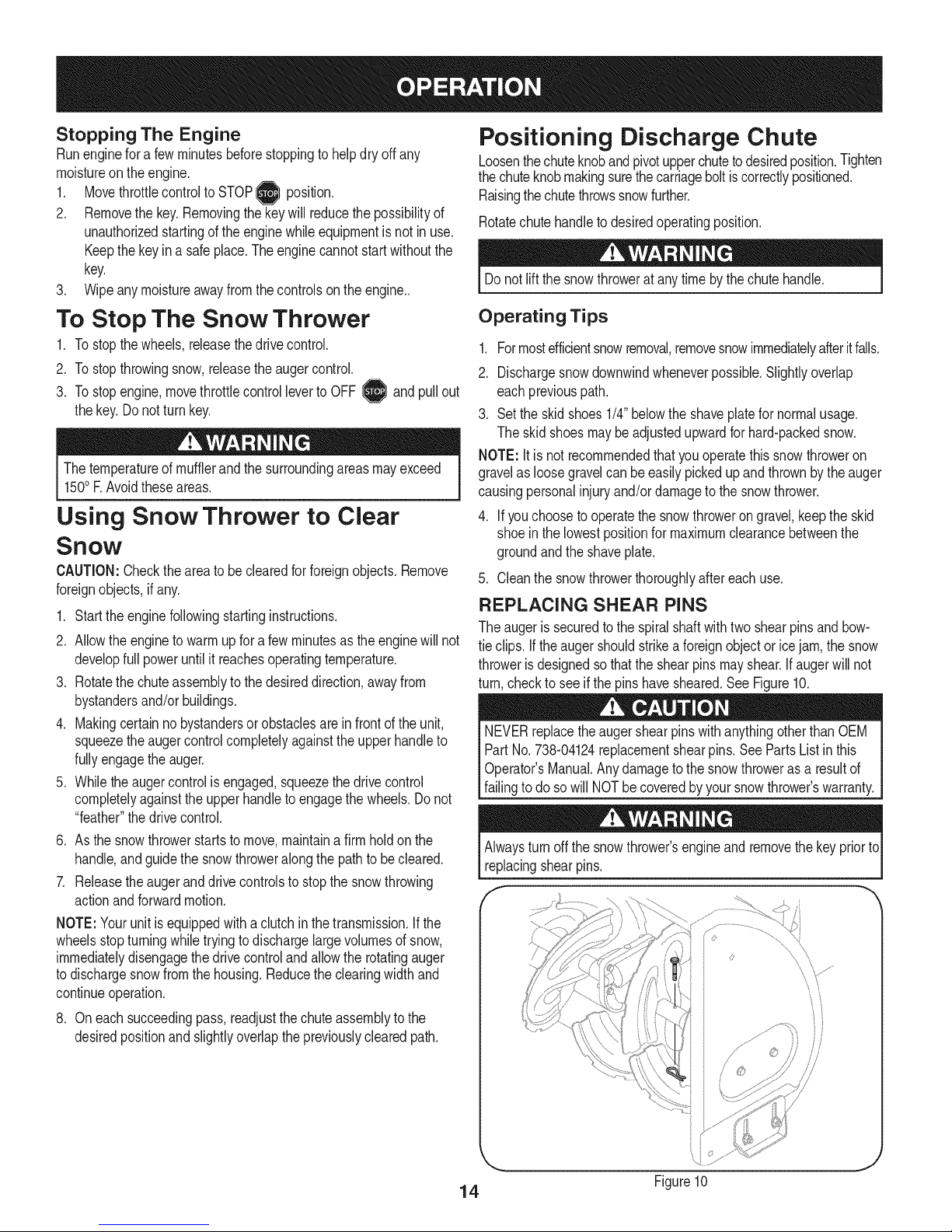
REPLACING SHEAR PINS
Theaugeris securedtothespiralshaftwithtwo shearpinsandbow-
tieclips. Iftheaugershouldstrikea foreignobjector icejam,thesnow
throwerisdesignedsothatthe shearpinsmayshear.Ifaugerwillnot
turn,checkto seeifthepins havesheared.SeeFigure10.
NEVERreplacetheaugershearpinswithanythingotherthanOEM
PartNo.738-04124replacementshearpins.SeePartsListinthis
Operator'sManual.Anydamagetothesnowthroweras a resultof
failingto do sowill NOTbecoveredbyyoursnowthrower'swarranty.
Alwaysturnoffthesnowthrower'sengineand removethekeypriorto
replacingshearpins.
f -,
f9
/
14
J
Figure10
Page 15
Beforeservicing,repairing,lubricatingorinspecting,disengageallcon-
trolsandstopengine.Waituntilallmovingpartshavecometoacomplete
stop.Removethekeytopreventunintendedstarting.Alwayswearsafety
glassesduringoperationorwhileperforminganyadjustmentsorrepairs.
Maintenance Schedule
Followthemaintenanceschedulegivenbelow.Thischartdescribes
serviceguidelinesonly.UsetheServiceLogcolumntokeeptrack
ofcompletedmaintenancetasks.Tolocatethe nearestSears
Service Centeror to scheduleservice,simplycontactSearsat
1-800-4-MY-HOME®.
EachUseandevery5
hours
1st5 hours
Annuallyor25hours
Annuallyor50hours
Annuallyor100hours
BeforeStorage 1. Fuelsystem 1.
1. Engineoillevel
2. Looseormissinghardware
3. Unitandengine.
1. Engineoil
1. Sparkplug
2. Controllinkagesand pivots
3. Wheels
4. GearshaftandAugershaft
1. Engineoil
1. Sparkplug
1. Check
2. Tightenor replace
3. Clean
1. Change
1. Check
2. Lubewithlightoil
3. Lubewithmultipurposeautogrease
4. Lubewithlightoil
1. Change
1. Clean,adjustgap,or replaceif
ENGINE MAINTENANCE
Checking Engine Oil
Beforelubricating,repairing,or inspecting,disengageall controls
Iandstopengine.Waituntilall movingpartshavecometo acomplete
_stop.
necessary
Runengineuntilit stopsfromlack
offuel
f
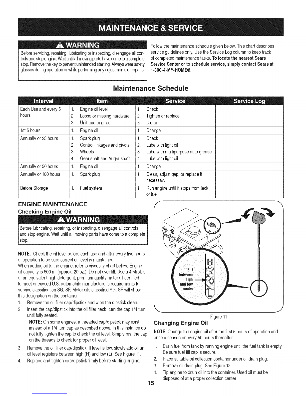
NOTE: Checktheoil levelbeforeeachuseandaftereveryfivehours
ofoperationtobesurecorrectoil levelismaintained.
Whenaddingoilto theengine,referto viscositychart below.Engine
oilcapacityis 600ml (approx.20 oz.). Donotover-fill.Usea4-stroke,
oran equivalenthighdetergent,premiumqualitymotoroilcertified
tomeetorexceedU.S.automobilemanufacturer'srequirementsfor
serviceclassificationSG, SRMotoroilsclassifiedSG,SFwillshow
thisdesignationonthecontainer.
1. Removetheoil fillercap/dipstickandwipethe dipstickclean.
2. Insertthe cap/dipstickintotheoilfillerneck,turnthecap1/4turn
untilfullyseated.
NOTE:On someengines,athreadedcap/dipstickmayexist
insteadofa 1/4turncap asdescribedabove.Inthisinstancedo
notfullytightenthe capto checktheoil level.Simplyrestthecap
onthethreadsto checkfor properoil level.
3. Removetheoil fillercap/dipstick.Iflevelislow,slowlyadd oiluntil
oil levelregistersbetweenhigh(H)andlow(L). SeeFigure11.
4. Replaceandtightencap/dipstickfirmlybeforestartingengine.
j
Figure11
Changing Engine Oil
NOTE:Changetheengineoil afterthefirst 5 hoursofoperationand
oncea seasonorevery50 hoursthereafter.
1. Drainfuelfromtankbyrunningengineuntilthefuel tankisempty.
Besurefuel fillcapis secure.
2. Placesuitableoilcollectioncontainerunderoil drainplug.
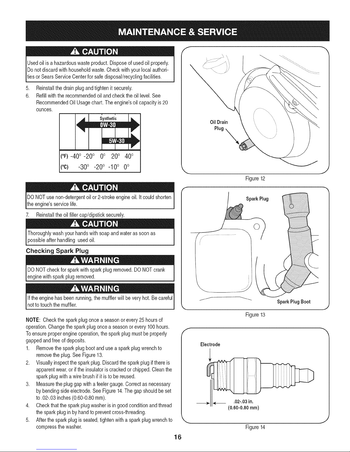
3. Removeoil drainplug.SeeFigure12.
4. Tipenginetodrainoil intothecontainer.Usedoil mustbe
disposedofat a propercollectioncenter
15
Page 16
Usedoil is a hazardouswasteproduct.Disposeof usedoil properly.
Donotdiscardwith householdwaste.Checkwithyourlocalauthori-
tiesor SearsServiceCenterfor safedisposal/recyclingfacilities.
.
Reinstallthedrainplugandtightenit securely.
6.
Refillwiththerecommendedoil andcheckthe oil level.See
RecommendedOil Usagechart.Theengine'soilcapacityis20
ounces.
i i
(%-400 -200 0o 200 400
f
Oil Drain
Plug
("c) -30° -20° -10° 0°
DONOTuse non-detergentoil or 2-strokeengineoil.Itcouldshorten
theengine'sservicelife.
7. Reinstalltheoilfillercap/dipsticksecurely.
Thoroughlywashyourhandswithsoapandwaterassoonas
possibleafterhandling usedoil.
Checking Spark Plug
DONOTcheckforsparkwithsparkplugremoved.DONOTcrank
enginewithsparkplugremoved.
Iftheenginehasbeenrunning,themufflerwillbevery hot.Becareful
notto touchthemuffler.
NOTE: Checkthesparkplugoncea seasonorevery25hoursof
operation.Changethesparkplugoncea seasonor every100hours.
Toensureproperengineoperation,the sparkplugmustbe properly
gappedandfreeof deposits.
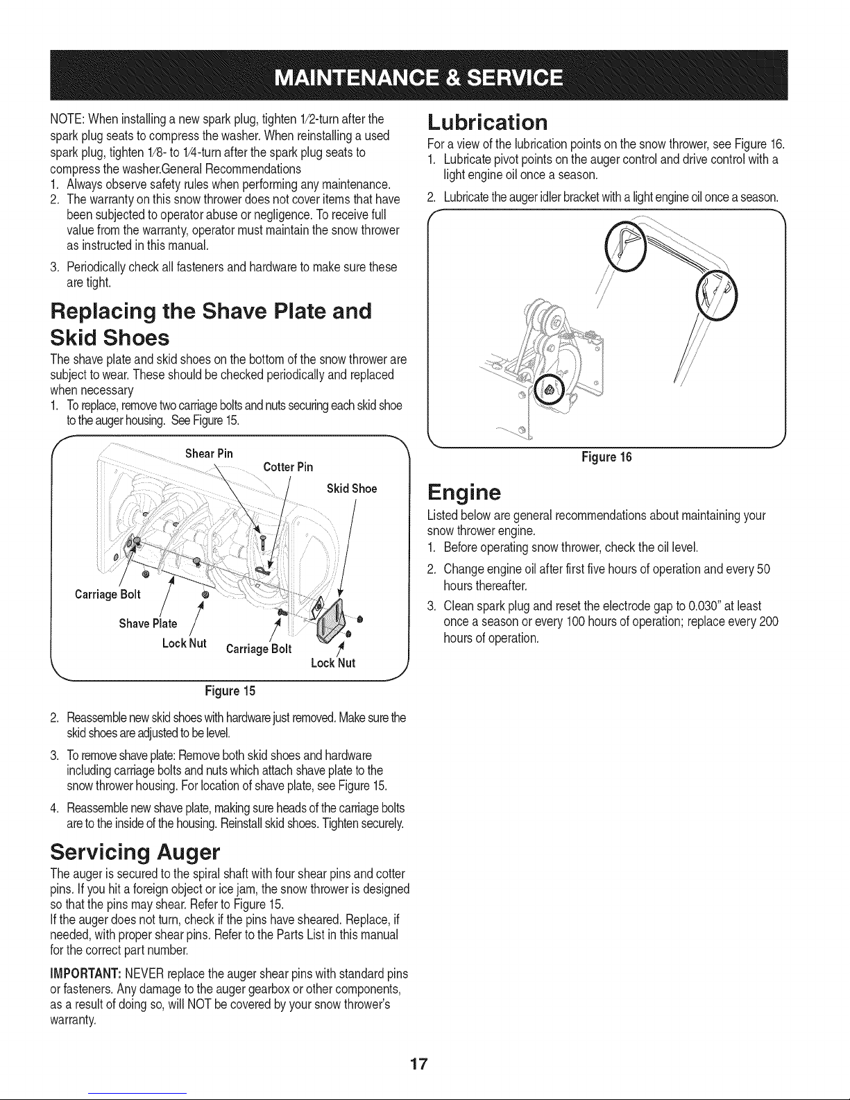
1. Removethesparkplugbootanduse a sparkplugwrenchto
removetheplug.See Figure13.
2. Visuallyinspectthesparkplug.Discardthesparkplugif thereis
apparentwear,orif the insulatoris crackedorchipped.Cleanthe
sparkplugwitha wirebrush ifitisto be reused.
3. Measurethe pluggapwitha feelergauge.Correctas necessary
bybendingsideelectrode.SeeFigure14.Thegapshouldbeset
to.02-.03inches(0.60-0.80ram).
4. Checkthatthe sparkplugwasherisingoodconditionandthread
thesparkplugin by handtopreventcross-threading.
5. Afterthesparkplugis seated,tightenwithasparkplugwrenchto
compressthewasher.
.J
Figure12
SparkPlug
SparkPlug Boot
Figure13
Electrode
___,. ,___ .02-.03in.
(0.60-0.80ram)
Figure14
16
Page 17
NOTE:Wheninstallinga newsparkplug,tighten1/2-turnafterthe
sparkplugseatsto compressthewasher.Whenreinstallinga used
sparkplug,tighten1/81to 1/41turnafterthe sparkplugseatsto
compressthewasher.GeneralRecommendations
1. Alwaysobservesafetyruleswhenperforminganymaintenance.
2. Thewarrantyonthissnowthrowerdoesnotcoveritemsthathave
beensubjectedto operatorabuseor negligence.Toreceivefull
valuefromthe warranty,operatormustmaintainthesnowthrower
asinstructedinthismanual.
3. Periodicallycheckall fastenersand hardwaretomakesurethese
aretight.
Replacing the Shave Plate and
Skid Shoes
Theshaveplateand skidshoesonthebottomofthe snowthrowerare
subjecttowear.Theseshouldbecheckedperiodicallyandreplaced
whennecessary
1. Toreplace,removetwocarriageboltsandnutssecuringeachskidshoe
totheaugerhousing.SeeFigure15.
f
ShearPin
CotterPin
SkidShoe
l
Carriage Bolt
ShavePlate /
LockNut
CarriageBolt /_
Figure15
/
LockNut
J
Lubrication
Fora viewof the lubricationpointsonthesnowthrower,seeFigure16.
1. Lubricatepivotpointsonthe augercontrolanddrivecontrolwitha
lightengineoilonce a season.
2. Lubricatetheaugeridlerbracketwitha lightengineoilonceaseason.
Figure16
Engine
Listedbelowaregeneralrecommendationsaboutmaintainingyour
snowthrowerengine.
1. Beforeoperatingsnowthrower,checkthe oil level.
2. Changeengineoilafterfirstfivehoursofoperationandevery50
hoursthereafter.
3. Cleansparkplugandresettheelectrodegapto 0.030"at least
oncea seasonorevery100hoursofoperation;replaceevery200
hoursof operation.
.
Reassemblenewskidshoeswithhardwarejustremoved.Makesurethe
skidshoesareadjustedtobelevel.
3.
Toremoveshaveplate:Removebothskidshoesandhardware
includingcarriageboltsandnutswhichattachshaveplatetothe
snowthrowerhousing.Forlocationofshaveplate,seeFigure15.
.
Reassemblenewshaveplate,makingsureheadsofthecarriagebolts
aretotheinsideof thehousing.Reinstallskidshoes.Tightensecurely.
Servicing Auger
Theaugeris securedto thespiralshaftwithfourshearpinsandcotter
pins.Ifyouhit a foreignobjectoricejam,thesnowthrowerisdesigned
sothatthe pinsmayshear.Referto Figure15.
Iftheaugerdoesnotturn,check ifthe pinshavesheared.Replace,if
needed,withpropershearpins.Refertothe PartsListinthis manual
forthecorrectpart number.
IMPORTANT:NEVERreplacetheaugershearpinswithstandardpins
orfasteners.Anydamagetotheaugergearboxor othercomponents,
asa resultof doingso,willNOTbecoveredbyyoursnowthrower's
warranty.
17
Page 18
Check V=Belts
Followinstructionsbelowtocheckconditionofdrivebeltsevery50
hoursof operation.
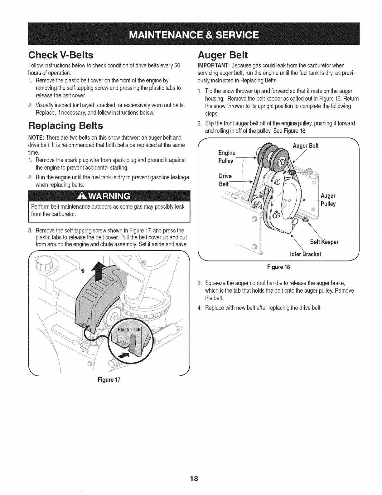
1. Removetheplasticbeltcoveronthe frontofthe engineby
removingtheself-tappingscrewandpressingtheplastictabsto
releasethebeltcover.
2. Visuallyinspectforfrayed,cracked,orexcessivelywornoutbelts.
Replace,ifnecessary,andfollowinstructionsbelow.
Replacing Belts
NOTE:Therearetwobeltson thissnowthrower:anaugerbelt and
drivebelt.it isrecommendedthatbothbeltsbereplacedatthe same
time.
1. Removethesparkplugwirefromsparkplugandgrounditagainst
theengineto preventaccidentalstarting.
2. Runtheengineuntilthefuel tankisdry topreventgasolineleakage
whenreplacingbelts.
Performbeltmaintenanceoutdoorsassomegasmaypossiblyleak
fromthecarburetor.
3. Removetheself-tappingscrewshowninFigure17,andpressthe
plastictabsto releasethebeltcover.Pullthebelt coverupand out
fromaroundtheengineandchuteassembly.Setitasideandsave.
Auger Belt
iMPORTANT:Becausegascouldleakfromthecarburetorwhen
servicingaugerbelt,runthe engineuntilthe fueltankisdry,asprevi-
ouslyinstructedinReplacingBelts.
1. Tip thesnowthrowerupandforwardso that itrestsonthe auger
housing. Removethe beltkeeperascalledoutinFigure19.Return
thesnowthrowertoitsuprightpositiontocompletethefollowing
steps.
2. Slipthe frontaugerbeltoffof theenginepulley,pushingit forward
and rollinginoff ofthepulley.SeeFigure18.
idlerBracket
Figure17
Figure18
Squeezethe augercontrolhandleto releasetheaugerbrake,
whichisthe tabthatholdsthebeltontotheaugerpulley.Remove
thebelt.
4. Replacewithnew beltafterreplacingthedrive belt.
18
Page 19
Drive Belt
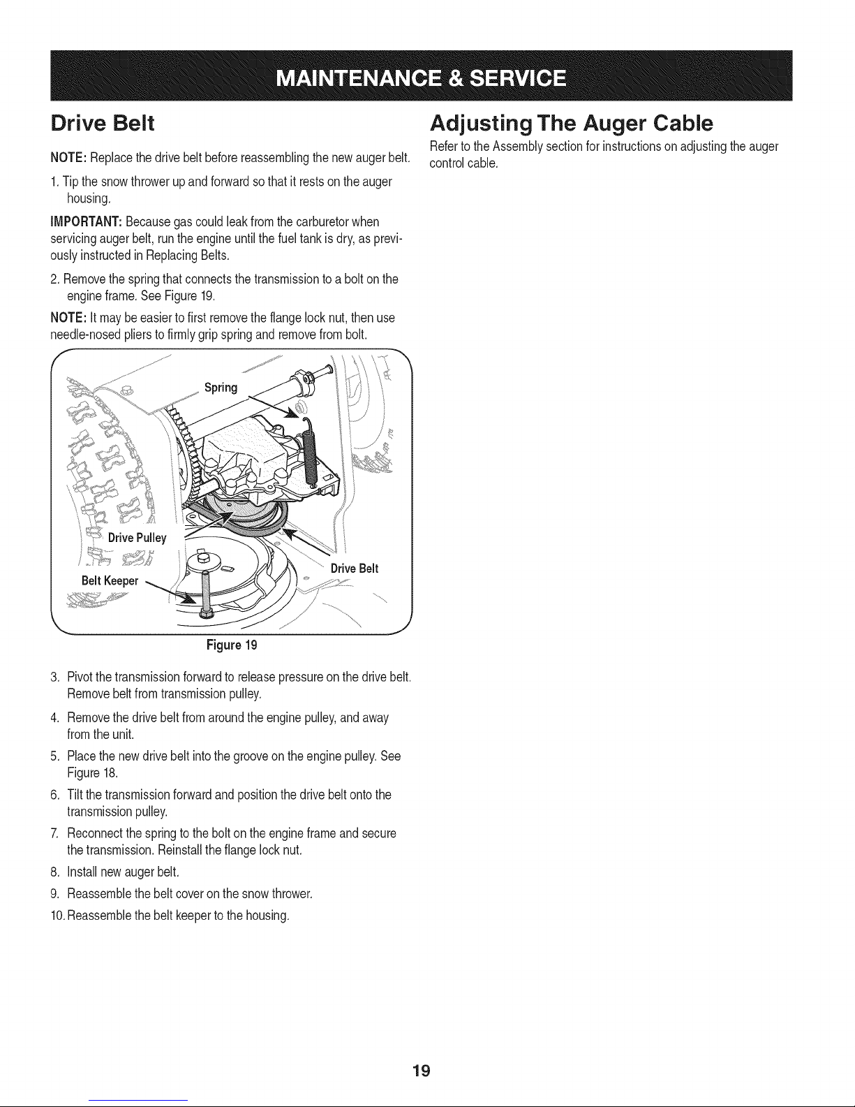
NOTE:Replacethedrivebelt beforereassemblingthenewaugerbelt.
1.Tip thesnowthrowerupandforwardsothat itrestson theauger
housing.
iMPORTANT:Becausegas couldleakfromthecarburetorwhen
servicingaugerbelt,runthe engineuntilthe fueltankis dry,asprevi-
ouslyinstructedin ReplacingBelts.
2.Removethespringthatconnectsthetransmissionto abolt onthe
engineframe.SeeFigure19.
NOTE:Itmaybeeasiertofirst removetheflangelocknut,then use
needle-nosedplierstofirmlygripspringandremovefrombolt.
F
Spring
Adjusting The Auger Cable
RefertotheAssemblysectionforinstructionson adjustingtheauger
controlcable.
........ _'*'_:" ...............DriveBelt
BeltKeeper
Figure19
3. Pivotthe transmissionforwardto releasepressureon thedrivebelt.
Removebeltfromtransmissionpulley.
4. Removethedrivebeltfromaroundtheenginepulley,andaway
fromtheunit.
5. Placethenewdrivebelt intothe grooveontheenginepulley.See
Figure18.
6. Tiltthe transmissionforwardandpositionthedrivebeltontothe
transmissionpulley.
7. Reconnectthespringto thebolt ontheengineframeandsecure
thetransmission.Reinstalltheflangelocknut.
8. Installnewaugerbelt.
9. Reassemblethe beltcoveronthe snowthrower.
10.Reassemblethe beltkeepertothe housing.
19
Page 20
Ifthe snowthrowerwillnotbe usedfor30 daysorlonger,or ifit isthe endofthesnowseasonwhenthelastpossibilityof snowisgone,the
equipmentneedstobestoredproperly.Followstorageinstructionsbelowtoensuretop performancefromthe snowthrowerformanymoreyears.
PREPARING ENGINE
Enginesstoredover30daysneedtobedrainedoffuelto prevent
deteriorationandgumfromforminginfuel systemoronessential
carburetorparts.Ifthegasolineinyourenginedeterioratesduring
storage,youmayneedto havethecarburetor,andotherfuelsystem
components,servicedor replaced.
1. Removeall fuelfromtank byrunningengineuntilitstops.Donot
attempttopourfuel fromtheengine.
2. Changetheengineoil.
3. Removesparkplugandpourapproximately1oz.(30 rnl)of clean
engineoil intothe cylinder.Pullthe recoilstarterseveraltimesto
distributetheoil,and reinstallthesparkplug.
4. Cleandebrisfromaroundengine,andunder,around,andbehind
muffler.Applya lightfilmofoilonanyareasthatare susceptible
torust.
• Storeina clean,dry andwellventilatedareaawayfromanyap-
pliancethatoperateswithaflameor pilotlight,suchasa furnace,
waterheater,or clothesdryer.Avoidanyareawitha spark
producingelectricmotor,orwherepowertoolsareoperated.
Neverstoresnowthrowerwithfuelintankindoorsorinpoorlyventi-
latedareas,wherefuelfumesmayreachanopenflame,sparkor pilol
lightas ona furnace,waterheater,clothesdryerorgasappliance.
PREPARING SNOW THROWER
Whenstoringthe snowthrowerin anunventilatedormetalstor-
age shed,careshouldbetakentorustprooftheequipment.Using
a lightoilor silicone,coattheequipment,especiallyanychains,
springs,bearingsandcables.
• Removealldirt fromexteriorofengineandequipment.
• Followlubricationrecommendations.
• Storeequipmentin a clean,dry area.
• Inflatethetirestothe maximumPSi.Referto tiresidewall.
• If possible,avoidstorageareaswithhighhumidity.
• Keepthe enginelevelin storage.Tiltingcancausefueloroil
leakage.
2O
Page 21
Beforeperforminganytypeofmaintenance/service,disengageall
controlsandstoptheengine.Waituntilallmovingpartshavecometoa
completestop.Removethekeytopreventunintendedstarting.Always
wearsafetyglassesduringoperationorwhileperforminganyadjustments
orrepairs.
Thissectionaddresses minor serviceissues.Tolocate the near-
est SearsService Centerorto scheduleservice,simplycontact
Searsat 1-800-4-MY-HOME®.
Enginefailsto start
1. Chokecontrolnotin Chokeposition.
2. Sparkplugwiredisconnected.
3. Faultysparkplug.
4. Fueltankemptyor stalefuel.
5. Enginenot primed.
6. Safetykeynot inserted.
7. Extensioncordnotconnected(whenusing
electricstart button)
Enginerunningerratically/
inconsistentRPM(huntingor
surging)
1. Enginerunningonchoke.
2. Fuellineblocked,or stalefuel.
3. Wateror dirtinfuelsystem.
4. Carburetoroutofadjustment.
5. Over-governedengine
Engineoverheats
Excessivevibration
1. Carburetornotadjustedproperly.
1. Loosepartsordamagedauger.
Lossof power 1. Sparkplugwireloose.
2. Gascap ventholeplugged.
Unitfailsto propelitself 1. Drivecablein needofadjustment.
2. Drivebeltlooseor damaged.
Unitfailstodischargesnow 1. Chuteassemblyclogged.
2. Foreignobjectlodgedin auger.
3. Augercableinneedof adjustment.
4. Augerbeltlooseor damaged.
5. Shearpin(s)sheared.
1. Movechokecontrolto Chokeposition.
2. Connectwireto sparkplug.
3. Clean,adjustgap,or replace.
4. Filltankwithclean,freshgasoline.
5. Primeengineasinstructedin theOperationSection.
6. Insertkeyfullyintothe switch.
7. Connectoneendof theextensioncordtotheelectric
starteroutletandthe otherendto a three-prong
120-volt,grounded,ACoutlet.
1. Movechokeleverto RUNposition.
2. Cleanfuel lineandfilltankwithfresh,cleangasoline.
3. Runengineuntilit stops.Refillwithfreshfuel.
4. Contacta SearsServiceCenter.
5. Contacta SearsServiceCenter.
1. ContactyourSearsParts& RepairCenter.
1. Stopengineimmediatelyanddisconnectsparkplug
wire.Tightenall boltsandnuts.If vibrationcontinues,
haveunit servicedbya SearsParts&RepairCenter.
1. Connectandtightensparkplugwire.
2. Removeiceandsnowfromgas cap.Becertainvent
holeisclear.
1. Adjustdrivecontrolcable.Referto Serviceand
Maintenancesection.
2. Replacedrivebelt.RefertoService&Maint.section.
1. Stopengineimmediatelyanddisconnectsparkplug
wire.Cleanchuteassemblyandinsideofauger
housingwithclean-outtoolor a stick.
2. Stopengineimmediatelyanddisconnectsparkplug
wire.Removeobjectfromaugerwithclean-outtool
or a stick.
3. Adjustaugercontrolcable.Referto Assembly
section.
4. Replaceaugerbelt.Referto Serviceand Mainte-
nancesection.
5. Replacewith newshearpin(s).
NEED MOR£ H_.LP?
o Find this and a[[ your other product manua|s online.
o Get answers from our team of home experts,
o Get a personalized maintenance p[an for your home.
o Find information and tools to help with home projects.
21
Page 22

Craftsman Snow Thrower IViodel 247.881700
\
/
22
Page 23

Craftsman Snow Thrower IViodel 247.881700
m
M
1
2
3
4
5
6
7
8
9
lO
11
12
13
14
15
16
17
18
19
2o
21
22
23
24
984-04037
71o-o4o71
71o-o451
710-0260A
720-04072A
731-04388A
731-04426A
936-0267
931-04127
931-04353
931-2636A
932-04111
712-04064
931-2643
731-2635
725-0157
710-0134
710-0520
710-04484
712-04063
712-04065
750-04852
715-04020
926-04012
ChuteAssembly
CarriageBolt5/16-18x1.0"
CarriageBolt5/16-18
CarriageBolt5/16-18x.62
WingKnob5/16-18
ChuteHandle
UpperChute
FiatWasher.385x .87x .06
LowerChute
ChuteRing
ChuteAdapter5" Dia.
ChuteAdjustmentSpring
FlangeLockNut 1/4-20
Clean-outTool
Clean-outToolMount
CableTie
CarriageScrew 1/4-20x 0.62"
HexBolt3/8-16x 1.50"
ABScrew5/16-18x .750
FlangeLockNut, 5/16-18
FlangeLockNut, 3/8-16
ShoulderSpacer
SpiralPin
PushOnNut
m
M
731-04218B
25
26
932-0611
27
736-0174
28
938-0281
29
941-0245
30
941-0309
31
950-04191
32
684-04358
33
784-0434-0637
34
790-00075
35
918-04292B
36
684-04113A-0637
37
684-04114A-0637
38
684-04166A-4043
39
714-04040
40
731-04870
41
936-0351
42
738-04124A
43
741-0493A
44
790-00087A-0637
45
790-00117-0637
46
784-5580-4043
47
710-04606A
48
929-0071A
Impeller
ExtensionSpring
WaveWasher
ShoulderScrew3/8-16
Hex FlangeBearing
BallBearing
Spacer
FlatIdler
AugerIdlerBracket
BearingHousing
AugerGearboxAssembly
AugerAssembly- LH
AugerAssembly- RH
AugerHousing,22"
BowTieCotterPin72
Spacer,1.25x.75x 1.00
FlatWasher
ShearPin,.25x 1.50
FlangeBushing
Hex BearingHousing
ShavePlate2.25x21.66LG
SkidShoe
Belt Keeper
ExtensionCord
23
Page 24

Craftsman Snow Thrower Model 247.881700
24
Page 25

Craftsman Snow Thrower IViodel 247.881700
m
1
71o-o572
2
71o-o6o5
3
71o-o4484
4
712-o4o64
5
720-04072A
6
725-0157
7
946-04642
8
946-04640
9
747-04394A-0637
lO
747-04405-0637
11
749-04147
12
749-04495-0637
13
990-00053
14
918-04296B
15
710-0809
16
710-1652
17
711-1364
18
914-0115
19
714-04040
2o
915-0249
717-04066A
21
22
917-04073A
932-0429A
23
24
936-0192
738-04184A
25
738-0924A
26
27
941-0245
28
741-04108
29
756-0625
CarriageScrew5/16-18x 2.25
Mach.Screw 1/4-20x 1.825
Screw5/16-18x .75
FlangeLockNut 1/4-20
WingKnob5/16-18
CableTie
DriveCable
AugerCable
AugerControl
DriveControl
LowerHandle
UpperHandle
HandleTab
TransmissionAssembly
TTScrew1/4-20x 1.25
Screw1/4-20x .625
ClevisPin
CotterPin1/8x 1.0
BowTie CotterPin72
RollPin
Pinion14T
Gear70T
ExtensionSpring
FlatWasher
ShoulderScrew1/4-20
ShoulderScrew1/4-28
Hex FlangeBearing
Hex FlangeBearing
CableRoller
m
M
784-o419C-4O43
30
31
790-00223A-0637
32
790-00224
934-04282B
33
734-04322
34
710-0627
35
736-0242
36
738-04321
37
910-0224
710-0654A
38
39
710-0696
710-1245B
4o
41
931-04162A
42
736-0247
43
736-0505
44
748-04067A
45
950-1355
46
950-1356
47
954-04013
48
954-04014
49
956-04024
5o
756-0569
51
729-04035
52
731-05672A
53
936-0160
54
936-0451
55
731-06749
56
952Z265-SUA
DriveHousingFrame
AugerCable Bracket
AugerCable Adj.Bracket
WheelAssySnowHogGray
Tube,Tire,4.10/3.50-4.0
LockBolt5/16-24x .75
BellWasher.34x .872x .06
Axle
HexScrew#10-16x.500
TT SemsScrew3/8-16x 1.0
HexBolt3/8-24x .875
LockBolt5/16-24x .875
BeltCover
FlatWasher.406IDx 1.25OD
FlatWasher.34IDx 1.50OD
Pulley:Adapter.75Dia.
Spacer.876x 1.25x .19
Spacer.876x 1.25x .86
V-Belt3/8 x 21.108Lg.
V-Belt3/8 x 26.680Lg.
AugerPulley
PulleyHalf
AmpSealedConnector
Spacer
FlatWasher.53x .93x .05
SaddleWasher
CableClip
Engine
25
Page 26

Craftsman Snow Thrower Model 247.881700
777S32636
1OO1£RO=NV313
"]VgNVN S,HOIVH3dOQV]U "_
"S]3VdHgS13AVU9NO9NlVU3dO
N3HMNOilgVOVUIX33Sn"SU3QNVISABIV39UVHOSiQ
133U10U3A3N'S3iUIlrNISI33F80 NMOUHI OIOMOl "t_
"_NJHOVN5NI3JAU3SHO9N199013Nn
3UOd3B03ddOIS3AVHSIUVd9NIAON]IV]JlN[iS_]QNVH
QNJH38NJVNBUONV '3NJON3dOIS'S83A33HOlff]O39VgNBSJQ"£
"31nHO39UVHOSiQ90qONnO1]OO1 InO'NV3qO3Sn "_
"133dQNVSQNVH31V1ffdNVNV3U39ffVUOU3]]3dNJHIIM
lOVlNO3"U39nVQNVU3]]3dNI 9NllVlOUNOUdArMYd33)1"L
777X43688
................OONOT....................
.....USEE85 ORFUEL'
CONTAiNiNG MORE
THAN10% ETHANOL
W
777122164
F •
777S32236
777i23249
m
|22164 AC
777122138
777D16343
777D16340
777D18033
26
Page 27

Craftsman Engine Model 265=SUA For Snow Model 247.881720
24
23
m
I
i
i19
!
i
120
i
i
i
i20
!
!
i
121
i
i
122
i
i
i
i23
!
i
i
124
i
951-11282
710-05001
751-14190
951-11289
712-04214
710-04915
951-10642B
m = I! O
MufflerAssembly
StudM8x36
MufflerStudKit
ExhaustPipeGasket
Nut,M8
BoltM6x12
MufflerShield
27
Page 28

Craftsman EngineModel 265=SUA For Snow Model 247.881720
41 _42
m
34
35
36
37
39
4O
41
42
43
951-10634
712-04213
951-11284
951-10757
951-10637
731-05632
951-10640
951-10635
710-04943
°0
Air CleanerHousing
Nut
ChokeKnob
ThrottleControlKnob
KeySwitch
Key
Choke PushRod
HeaterBox
BoltM6x28
37
35
D = O O
28
Page 29

Craftsman Engine Model 265=SUA For Snow Model 247.881720
63
132- 6asketKit-Complete
133- 6asketKit-External
134-CompleteEngine
62
29
Page 30

Craftsman Engine IViodel 265=SUA For Snow IViodel 247.881720
m
5O
51
52
53
54
55
56
57
58
59
6O
61
62
63
64
65
66
67
68
69
951-11688
951-11632
951-11900
951-11901
710-04915
951-11113
951-11573
951-14053
736-04461
951-11902
714-04078
951-11575
951-11369
951-10307
951-11247A
951-11576
715-04092
715-04096
951-11371
951-12125
951-11246
D = O
PistonRingSet
PistonPinSnapRing
Piston
PistonPin
BoltM6x12
Air Shield
ConnectingRodAssembly
GovernorArm Shaft
Washer5.2xl.9
GovernorSeal
CotterPin
CamshaftAssembly
RadialBallBearing,6205
WoodruffKey
CrankshaftKit
(Incl.62-64,74,79)
GovernorGear/ShaftAssembly
DowelPin7x14
DowelPin9x14
CrankcaseCoverGasket
CrankcaseCover
CrankcaseCoverKit
(Incl.62,68-74)
m
7O
71
73
74
75
76
77
78
79
131
132
133
134
710-04932
951-11283
951-11577
951-11368
951-11248A
951-11062B
951-11350
736-04440
710-04906
951-11370
951-10641
951-11061A
951-10661B
952Z265-SUA
D = O O
BoltM8x32
Oil FillPlugAssembly
O-Ring15.8x2.5
OilSeal,25x41.25x6
CrankcaseKit
(Incl.59,62,74,75,79)
ShortBlockAssembly
(Incl.4,21,27-29,32,44,
46,47,80-53,56-79)
Oil DrainPipeAssy.
Washer10x16x1.5
Oil DrainPlug
OilSeal25x41.25x6
Oil DrainAssembly
GasketKit- Complete
(Incl.4,21,27-29,32,44,
58,59,68,74,77,79)
GasketKit- External
(Incl.4,21,27-29,32,77)
CompleteEngine
3O
Page 31

Craftsman Engine Model 265=SUA For Snow Model 247.881720
15 44 _)
13
48
u_ _ _'45
10
17
132-GasketKit-Complete
133-GasketKit-External
134-CompleteEngine
\6
31
Page 32

Craftsman Engine IViodel 265=SUA For Snow IViodel 247.881720
m
1
2
3a
3b
4
5
6
7
8
9
10
11
12
13
14
15
16
17
18
44
45
46
47
48
49
130
132
133
134
710-04968
951-11054A
731-07059
726-04101
951-11565
951-12000
951-11892
751-11124
751-11123
951-11893
710-04902
951-12002
951-12003
951-12004
951-11894
710-04933
951-11895
751-14195
951-10292
951-11898
951-10648
951-11899
715-04108
951-10647A
951-10647A
951-12626
951-11061A
951-10661B
952Z265-SUA
D = W O
BoltM6x16
ValveCover
BreatherHose
BreatherHoseClamp
ValveCoverGasket
ValveSpringRetainer(Intake)
RockerArmAssembly
Nut,PivotLocking
AdjustingNut,Valve
RockerArm
Bolt,Pivot
ExhaustLashCap
ValveSpringRetainer(Exhaust)
ValveSpring
ValveSeal(Intake)
BoltM8x55
PushRodGuide
CylinderHeadAssembly
(Incl.4-14,16,17,21,27,
29,44,48,49)
SparkPlug/F6Rtc
Gasket,CylinderHead
PushRod Kit
Tappet
DowelPin 10x16
ValveKit
ValveKit
ValveCoverKit
GasketKit- Complete
(Incl.4,21,27-29,32,44,
58,59,68,74,77,79)
GasketKit- External
(Incl.4,21,27-29,32,77)
CompleteEngine
32
Page 33

Craftsman Engine IViodel 265=SUA For Snow IViodel 247.881720
135- CarburetorKit
27
28
3O
w
31_
33
Page 34

Craftsman Engine IViodel 265=SUA For Snow IViodel 247.881720
m
25
26
27
28
29
30
30
31
32
33
135
a
b
C
d
e
f
g
h
I
J
k
I
m
n
o
P
q
r
s
t
U
V
W
X
Y
710-04939
710-04910
951-11567
951-11896
951-11569A
951-10639A
951-11824
951-12705
951-11897
951-11112
951-14050
n/a
n/a
n/a
n/a
710-05469
736-04638
n/a
n/a
n/a
n/a
951-11699
951-11906
n/a
n/a
n/a
951-12875
n/a
n/a
n/a
951-11589
n/a
951-11348
710-04945
951-11349
710-04938
D = O O
StudM6x117
StudM6x105
CarburetorInsulatorGasket
CarburetorInsulator
CarburetorGasket
PrimerAssembly
PrimerBulb
CarburetorAssembly
CarburetorGasketPlate
ChokeControl
CarburetorKit
(Incl.h,n,o,p,q,r,s,t,v,x)
ChokeShaft
ChokePlate
ThrottleShaft
ThrottlePlate
ScrewM3x6
LockWasher
Gasket,ThrottlePlate
IdleJet Assembly(0.34)
IdleSpeedAdjustingScrew
PrimerPipe
PrimerHose
HoseClamp
CarburetorBody
FloatPin
EmulsionTube(P18-019)
NeedleValve
MainJet(#73)
NeedleValveSpring
Float
FuelBowlO-Ring
FuelBowl
FuelBowlMountingBoltGasket
FuelBowlMountingBolt
FuelBowlDrainBoltGasket
FuelBowlDrainBolt
34
Page 35

Craftsman Engine Model 265-SUA For Snow Model 247.881720
82
87 94
85
86
92/° _3
93
m
8O
81
82
83
85
86
87
88
89
91
92
93
94
951-10646
951-11110
710-04940
710-04919
951-12416
951-10934
951-10911
712-04209
710-04915
951-10663A
736-04455
710-04974
951-14151
_89 _89 92-_ _/93
D = O O
IgnitionCoilAssembly
Air FlowShield
BoltM6xlO
BoltM6x25
Flywheel
CoolingFan
StarterCup
Nut,Special,M14x1.5
BoltM6x12
BlowerHousing
Gasket6
BoltM6xlO
RecoilStarter
35
Page 36

Craftsman Engine Model 265=SUA For Snow Model 247.881720
96 103 _--117
,115
116
m
95
96
97
98
99
1CO
102
103
104
105
106
107
951-10758
710-05103
951-11108
951-11935
951-10664
951-10665
951-11106
712-04212
710-04908
951-11700
951-10650
710-04915
9s 99
95
D = O
PrimerBracket
BoltM6x12
GovernorSystemShield
GovernorSpring
ThrottleLinkageSpring
ThrottleLinkage
GovernorArm
NutM6
GovernorArmBolt
FuelHoseClamp
FuelLineKit
BoltM6x12
107
m
108
109
110
111
112
113
114
115
116
117
118
951-11914
710-04905
710-04915
951-11913
951-11381
951-10656
951-11904
951-12482
951-12533
951-11933
951-10653B
D = O O
DipstickDecorationCover
Bolt
BoltM6x12
Oil FillTubeAssembly
O-Ring
Oil FillTube
O-Ring
DipstickAssembly
FuelCapAssembly
FuelLevelIndicator
FuelTankAssembly
36
Page 37

Craftsman Engine Model 265=SUA For Snow Model 247.881720
119
120
121
m
i
1119
1
1
1
i 120
!
i
1121
1
1
1
i 122
1
1
1
i 123
!
i
i 124
1
1
1
i 125
!
!
i
i 126
1
1
i 127
1
1
1
i 128
!
i
1
i 129
1
122
710-04914
951-11680
951-11114
712-05015
710-04935
710-04965
710-05182
715-04088
951-10645A
710-04915
951-11109
123
126
126
_i _128
29
D = O !
BoltM6xlO
WireClip
SwitchHousingMountingBracket
Nut,M6
BoltM4x60
BoltM4x55
BoltM6x32
DowelPin8x8
ElectricStarter
BoltM6x12
BlowerHousingShield
37
Page 38

38
Page 39

39
Page 40

MTD CONSUMER GROUP INC (MTD), the California Air Resources Board (CARB)
and the United States Environment Protection Agency (U. S. EPA)
Emission Control System Warranty Statement
(Owner's Defect Warranty Rights and Obligations)
EMISSIONCONTROLSYSTEMCOVERAGEISAPPLICABLETOCERTIFIEDENGINESPURCHASEDINCALIFORNIAIN2005ANDTHERE-
AFTER,WHICHAREUSEDINCALIFORNIA,ANDTOCERTIFIEDMODELYEAR2005ANDLATERENGINESWHICHAREPURCHASEDAND
USEDELSEWHEREINTHEUNITEDSTATES.
Californiaandelsewherein theUnitedStatesEmissionControlDefectsWarrantyCoverage
TheCaliforniaAir ResourcesBoard(CARB),U.S.EPAandMTDarepleasedtoexplaintheemissionscontrolsystemwarrantyonyour modelyear
2006andlatersmalloff-roadengine.InCalifornia,newsmalloff-roadenginesmustbe designed,builtand equippedtomeettheStatesanti-smog
standards.Elsewhereinthe UnitedStates,newnon-road,spark-ignitionenginescertifiedfor model2005andlater,mustmeetsimilarstandardsset
forthbythe U.S.EPA.MTDmustwarrantytheemissioncontrolsystemonyourenginefor theperiodof timelistedbelow,providedtherehasbeen
noabuse,neglector impropermaintenanceofyour smalloff-roadengine.
Youremissioncontrolsystemmayincludepartssuchasthecarburetor,fuel-injectionsystem,the ignitionsystem,andcatalyticconverter,fueltanks,
fuellines,fuel caps,valves,canisters,filters,vaporhoses,clamps,connectors,andotherassociatedemission-relatedcomponents.
Whereawarrantableconditionexists,MTDwill repairyoursmalloff-roadengineat nocosttoyourincludingdiagnosis,partsand labor.
MANUFACTURER'S WARRANTY COVERAGE:
Thisemissionscontrolsystemiswarrantedfor twoyears.Ifanyemission-relatedpartonyourengineisdefective,the partwill berepairedor
replacedbyMTD.
OWNER'S WARRANTY RESPONSIBILITIES:
Asthe smalloff-roadengineowner,youare responsibleforthe performanceofthe requiredmaintenancelistedinyourOwner'sManual.MTD
recommendsthatyouretainall yourreceiptscoveringmaintenanceson yoursmalloff-roadengine,butMTDcannot denywarrantysolelyfor the
lackofreceiptsor foryour failureto ensuretheperformancetoallscheduledmaintenance.
Asthe smalloff-roadengineowner,youshouldhoweverbeawarethatMTDmaydenyyourwarrantycoverageifyoursmalloff-roadengineorpart
hasfaileddue toabuse,neglect,impropermaintenanceor unapprovedmodifications.
Youare responsibleforpresentingyour smalloff-roadenginetoanAuthorizedMTDServiceDealeras soonas a problemexists.Thewarranted
repairsshouldbe completedina reasonableamountoftime,nottoexceed30 days.
Ifyouhaveanyquestionsregardingyourwarrantyrightsand responsibilities,youshouldcontacta MTDServiceRepresentativeat 1-800-800-7310
andaddressisMTDCONSUMERGROUP,RO.Box361131,ClevelandOH,44136-0019.
DEFECTS WARRANTY REQUIREMENTS FOR 1995 AND LATER SMALL OFF-ROAD ENGINES:
Thissectionappliesto 1995andlater smalloff-roadengines.The warrantyperiodbeginsonthedatetheengineor equipmentisdeliveredtoan
ultimatepurchaser.
(a) GeneralEmissionsWarrantyCoverage_
MTDmustwarranttothe ultimatepurchaserandeachsubsequentpurchaserthatthe engineis:
(1)Designed,built,andequippedsoasto conformwithallapplicableregulationsadoptedbytheAirResourcesBoardpursuantto itsauthorityin
Chapters1and2,Part5, Division26of theHealthandSafetyCode;and
(2) Freefromdefectsin materialsandworkmanshipthatcausethefailureofa warrantedparttobeidenticalin all materialrespectsto thepartas
describedin theenginemanufacturer'sapplicationfor certificationfora periodoftwoyears.
.(b)The warrantyonemissions-relatedpartswillbe interpretedas follows:
(1)Anywarrantedpartthatisnot scheduledforreplacementas requiredmaintenanceinthewritteninstructionsrequiredby Subsection(c)
mustbewarrantedforthewarrantyperioddefinedinSubsection(a)(2).Ifanysuchpartfailsduringthe periodof warrantycoverage,it mustbe
repairedor replacedbyMTDaccordingto Subsection(4)below.Anysuchpart repairedor replacedunderthewarrantymustbewarrantedfor
theremainingwarrantyperiod.
(2)Anywarrantedpartthat isscheduledonlyfor regularinspectioninthewritteninstructionsrequiredby Subsection(c) mustbewarrantedfor
thewarrantyperioddefinedinSubsection(a)(2).A statementinsuchwritteninstructionstotheeffectof"repairorreplaceasnecessary"will
notreducetheperiodof warrantycoverage.Anysuchpartrepairedor replacedunderwarrantymustbe warrantedfortheremainingwarranty
period.
(3) Anywarrantedpartthat whichisscheduledfor replacementas requiredmaintenancein thewritteninstructionsrequiredby Subsection(c)
mustbewarrantedfortheperiodof timepriortothe firstscheduledreplacementpointforthat part.Ifthe partfailspriorto thefirst scheduled
replacement,thepart mustbe repairedor replacedbyMTDaccordingto Subsection(4) below.Any suchpart repairedor replacedunder
warrantymustbewarrantedfortheremainderoftheperiodpriortothefirstscheduledreplacementpointfor thepart.
(4) Repairorreplacementofany warrantedpartunderthewarrantyprovisionsof thisarticlemustbe performedat nochargetotheownerat a
warrantystation.
(5) Notwithstandingtheprovisionsof Subsection(4)above,warrantyservicesorrepairsmustbe providedatall MTDdistributioncentersthat
arefranchisedto servicethesubjectengines.
Page 41

(6)Theownermustnotbechargedfordiagnosticlaborthatleadstothedeterminationthatawarrantedpartisinfactdefective,providedthat
suchdiagnosticworkisperformedatawarrantystation.
(7)Theenginemanufacturerisliablefordamagestootherenginecomponentsproximatelycausedbyafailureunderwarrantyofanywarranted
part.
(8)Throughouttheengine'swarrantyperioddefinedinSubsection(a)(2),MTDwillmaintainasupplyofwarrantedpartssufficienttomeetthe
expecteddemandforsuchparts.
(9)Anyreplacementpartmaybeusedintheperformanceofanywarrantymaintenanceorrepairsandmustbeprovidedwithoutchargetothe
owner.SuchusewillnotreducethewarrantyobligationsofMTD.
(10)Add-onormodifiedpartsthatarenotexemptedbytheAirResourcesBoardmaynotbeused.Theuseofanynon-exemptedadd-onor
modifiedpartsshallbegroundsfordisallowingawarrantyclaimmadeinaccordancewiththisarticle.Theenginemanufacturershallnotbe
liableunderthisarticletowarrantfailuresofwarrantedpartscausedbytheuseofnon-exemptedadd-onormodifiedpart.
(c)MTDwillincludea copyofthe followingemissionwarrantypartslistwitheach newengine,usingthoseportionsof thelistapplicableto the
e__&gine.
(1)FuelMeteringSystem
•Coldstart enrichmentsystem(softchoke)
,,Carburetorandinternalparts
•FuelPump
•FuelTank
(2)Air InductionSystem
•Aircleaner
•Intakemanifold
(3) IgnitionSystem
•Sparkplug(s)
•MagnetoIgnitionSystem
(4)ExhaustSystem
Catalyticconverter
•SAI(Reedvalve)
(5) MiscellaneousItemsUsedin AboveSystem
Vacuum,temperature,position,timesensitivevalvesandswitches
Connectorsandassemblies
(6) Evaporativecontrol
•FuelHosecertifiedforARBevaporativeemissionof2006.
•FuelHoseClamps
Tetheredfuelcap
Carboncanister
•Vaporlines
GD0C-100174Rev.B
Page 42

Look For Relevant Emissions Durability Period and
Air index information On Your Engine Emissions Label
Engines that are certified to meet the California Air Resources Board (CARB) Tier 2 Emission Standards must
display information regarding the Emissions Durability Period and the Air Index. Sears Brands Management
Corporation makes this information available to the consumer on our emission labels.
The Emissions Durability Period describes the number of hours of actual running time for which the engine is
certified to be emissions compliant, assuming proper maintenance inaccordance with the Operating & Mainte-
nance Instructions. The following categories are used:
Moderate: Engine is certified to be emission compliant for 125 hours of actual engine running time.
Intermediate: Engine is certified to be emission compliant for 250 hours of actual engine running time.
Extended: Engine is certified to be emission compliant for 500 hours of actual engine running time.
For example, a typical walk-behind lawn mower is used 20 to 25 hours per year. Therefore, the Emissions
Durability Period of an engine with an intermediate rating would equate to 10 to 12 years.
The Air index is a calculated number describing the relative level of emissions for a specific engine family. The
lower the Air Index, the cleaner the engine. This information is displayed in graphical form on the emissions label.
After July 1,2000, Look For Emissions Compliance Period
On Engine Emissions Compliance Label
After July 1, 2000 certain Sears Brands Management Corporation engines will be certified to meet the United
States Environmental Protection Agency (USEPA) Phase 2 emission standards. For Phase 2 certified engines, the
Emissions Compliance Period referred to on the Emissions Compliance label indicates the number of operating
hours for which the engine has been shown to meet Federal emission requirements.
For engines less than 225 cc displacement, Category C = 125 hours, B = 250 hours and A = 500 hours.
For engines of 225 cc or more, Category C = 250 hours, B = 500 hours and A = 1000 hours.
This isa generic representation of the emission label typically found on a certified engine.
FAMILYYBSXS.3192VA 274812
GDOC-100182Rev.B
42
Page 43

Congratulations on making a smart purchase. Your new Craftsman® product is designed and
manufactured for years of dependable operation. But like all products, it may require repair
from time to time. That's when having a Repair Protection Agreement can save you money and
aggravation.
Here's what the Repair Protection Agreement* includes:
[] Expert service by our 10,000 professional repair specialists
[] Unlimited service and no charge for parts and labor on all covered repairs
[] Product replacement up to $1500 if your covered product can't be fixed
[] Discount of 25% from regular price of service and related installed parts not covered by the
agreement; also, 25% off regular price of preventive maintenance check
[] Fast help by phone - we call it Rapid Resolution - phone support from a Sears representative.
Think of us as a "talking owner's manual."
Once you purchase the Repair Protection Agreement, a simple phone call is all that it takes for you
to schedule service. You can call anytime day or night, or schedule a service appointment online.
The Repair Protection Agreement is a risk-free purchase. If you cancel for any reason during the
product warranty period, we will provide a full refund. Or, a prorated refund anytime after the
product warranty period expires. Purchase your Repair Protection Agreement today!
Some limitations and exclusions apply. For prices and additional information in the U.S.A.
call 1=800=827=6655.
*Coverage in Canada varies on some items. For full details call Sears Canada at 1=800=361=
6665.
Sears Installation Service
For Sears professional installation of home appliances, garage door openers, water heaters, and
other major home items, in the U.S.A. or Canada call 1=800=4=MY=HOME®.
43
Page 44

Declaraci6n de garantia ............................ Pagina 44
Practicas operaci6n seguras ..................... Pagina 45
Montaje ...................................................... Pagina 49
Operaci6n .................................................. Pagina 53
Servicio y Mantenimiento .......................... Pagina 57
Almacenamiento fuera de temporada ....... Pagina 62
GARANTiA COMPLETA CRAFTSMAN POR DOS AltOS
PORDOSANOSapartir dela fechade lacornpra,esteproductoest,.garantizadopordefectosenlos rnaterialesyla rnanodeobra.
Losproductosdefectuososser_.nreparadossin costooreernplazadossin costosi la reparaci6nnoest,.disponiNe.
La presentegarantiaseanulasiseutilizaesteproductoalgunavezparaprestarservicioscornercialeso sise Ioalquilaa otra persona.
Paraobtener informaci6nsobreel alcancede la garantiay solieitarlareparaci6no el reemplazo,visite elsitio Web:www.craftsman.com
Esta garantiaeubre0NICAMENTElosdefectos en los rnaterialesy en la manode obra. Estagarantia NOcubre:
• Elernentosno renovablesquepuedendesgastarsepor eluso normal,duranteelplazodela garantia,incluyendoentreotros,lasbarrenas,
laspaletasdelas barrenas,loscortadoresde desplazarniento,laszapatasantideslizantes,la placade raspado,lospasadoresdecuchilla,
la bujia,elfiltrode aire,lascorreasy el filtrodeaceite.
• Serviciosde rnantenirnientoest_.ndar,carnbiosdeaceiteo afinaci6n.
• Carnbiode neurn_.ticoso reparacionesporpinchadurasconobjetosexternoscornoclavos,espinas,toconeso vidrios.
• Reernplazoo reparaci6nde neurn_.ticoso ruedascornoresultadodel desgastenormal,unaccident&o funcionarniento
o rnantenirnientoincorrectos.
• Reparacionesrequeridascornoresultadodel usoinadecuadopot partedeloperador,incluyendoentreotrosel da_oocasionadoporobjetos
queirnpactanla rn_.quinay quetuercenel bastidor,el ejede labarrena,etc.,odebidoaqueelmotorrueaceleradoenexceso.
• Reparacionesnecesariasdebidoanegligenciadeloperador,incluyendoentreotros,da_osrnec_.nicoyel_ctricoocasionadopor
unalrnacenarnientonoapropiado,fallaporel usodeaceitede gradoy/o cantidadnoapropiadoso fallapornodarrnantenirniento
alequipodeacuerdoconlasinstruccionescontenidasenel manualdeloperador.
• Lirnpiezao reparacionesdel motor(sisternade combustible)debidasa combustiblequesedeterrninaest,.contarninadou oxidado(viejo).
Engeneral,elcombustibledebeutilizarseen unperiodono mayorde 30dias a partirdesuadquisici6n.
• Eldeterioroydesgastenormalde losacabadosexteriores,oreernplazode laetiquetadelproducto.
Soluci6n de problemas .............................. Pagina 63
Lista de piezas ........................................... Pagina 22
Acuerdo de protecci6n para reparaciones .... Pagina 67
NOmero de servicio ................................ 01tima pagina
Estagarantialeotorgaderechoslegalesespecificos,peroustedpodriagozardeotrosderechosenraz6nde sulugarde residencia.
Sears Brands Management Corporation, Hoffman Estates, IL 60179
Tipodeaceitedelmotor:
Capacidadde aceitedel motor:
Capacidadde combustible:
Bujias:
Separaci6ndelas bujias:
©SearsBrands,LLC
5W-30
20onzas
2.3cuartos
FeRTC(F6TC)
.020"to.030"
N_mero de rnodelo ..........................................................
N_mero de sede..............................................................
Feehadeeompra .............................................................
RegistrearribaelnOrnerodel rnodelo,el nOrnerode serieyla fecha
de cornpra
44
Page 45

Lapresenciadeeste sfrnboloindicaque setratadeinstrucciones
irnportantesde seguridadquesedebenrespetarparaevitar
ponerenpeligrosuseguridadpersonaly/omaterialy lade otras
personas.Leay sigatodaslas instruccionesdeestemanualantes
de poneren funcionarnientoestarn_.quina.Si no respetaestas
instruccionespodrfaprovocarlesionespersonales.Cuandoveaeste
sfrnbolo,ipresteatenci6nala advertencia!
Estarn_.quinarueconstruidaparaseroperadadeacuerdocon
lasreglasde seguridadcontenidasenestemanual.AIigualque
concualquiertipodeequipornotorizado,undescuidoo errorpor
partedeloperadorpuedeproducirlesionesgraves.Estarn_.quina
escapazde arnputarrnanosy piesy dearrojarobjetoscongran
fuerza.Deno respetarlasinstruccionesde seguridadsiguientesse
puedenproducirlesionesgraveso larnuerte.
PROPOSICION 65 DE CALIFORNIA
Elescapedel motordeesteproducto,algunosde suscornponentes
y algunoscornponentesdelvehfculocontieneno liberansustancias
qufrnicasqueelestadodeCaliforniaconsideraque puedenproducir
c_.ncer,defectosde nacirnientouotrosproblernasreproductivos.
CAPACITACI6N
• Lea,entiendaycurnplatodaslas instruccionesincluidasen
la rn_.quinayen losrnanualesantesdernontarlay utiNzarla.
Guardeestemanualenun lugarseguroparaconsultasfuturasy
peri6dicas,asf cornoparasolicitarrepuestos.
• Leael ManualdelOperadorysigatodaslasadvertenciase
instruccionesdeseguridad.Elfracasode hacerasf puedecausar
la heridaseriaal operadory/o personaspresentes.
• Farniliarfcesecontodosloscontrolesycon el usoadecuado
delosrnisrnos.Sepac6rnodetenerlarn_.quinay desactivarlos
controlesr_.pidarnente.
• No perrnitanuncaque los ni_osrnenoresde 14a_osutilicen
estarn_.quina.Losni_osde 14a_osen adelantedebenleery
entenderlasinstruccionesde operaci6ny norrnasdeseguridad
contenidaseneste manual,yen la rn_.quinaydebenserentrena-
dosy supervisadosporun adulto.
• Nuncaperrnitaquelosadultosoperenestarn_.quinasin recibir
antesla instrucci6napropiada.
• Losobjetosarrojadosporla rn_.quinapuedenproducirlesiones
graves.Planifiqueel patr6nenel queva air arrojandonievepara
evitarque ladescargade materialse realicehacialoscarninos,
losobservadores,etc.
• Mantengaalosobservadores,ayudantes,rnascotasy ni_ospor
Iornenosa 75piesde larn_.quinarnientrasla rnisrnaest,.en
funcionarniento.Detengalarn_.quinasialguienseacerca.
• Seaprecavidoparaevitarpatinarseocaerseespecialrnente
cuandooperala rn_.quinaenreversa.
Su responsabilidad--Restrinja el usode estarn_.quina
rnotorizadaalas personasquelean,cornprendany respetenlas
advertenciase instruccionesqueaparecenenestemanualyen la
rn_.quina.
iGUARDEESTASINSTRUCCIONES!
PR E PARATIVO S
Inspeccionerninuciosarnenteel_.readondeutilizar_,el equipo.Saque
todoslosfelpudos,peri6dicos,trineos,tablas,cablesy otrosobjetos
extra_osconlosquepodrfatropezaro quepodrfanserarrojadospor
labarrena/irnpulsor.
• Paraprotegerselosojosutilicesiernpreanteojosoantiparras
de seguridadrnientrasoperala rn_.quinao rnientraslaajusta
o repara.Losobjetosarrojadosquerebotanpuedenproducir
lesionesocularesgraves.
• Nooperelarn_.quinasin la vestirnentaadecuadaparaestaral
airelibreen invierno.Noutilicealhajas,bufandaslargasuotras
prendassueltasquepodrfanenredarseenlas partesrn6viles.
UtiNceun calzadoespecialparasuperficiesresbaladizas.
• Useun prolongadory untornacorrientedetrescablescon
conexi6na tierraparatodaslas rn_.quinasconrnotoresde
encendidoel_ctrico.
• Ajustelaalturade lacajadeltornacorrienteparaNrnpiarla grava
o lassuperficiesconpiedrastrituradas.
• Desengranetodaslaspalancasdecontrolantesde arrancarel
motor.
• Nuncaintenterealizarajustesrnientrasel motorest,.enrnarcha
exceptoenlos casosespecfficarnenterecornendadosen el
manualdeloperador.
• Dejequeelmotory la rn_.quinaseadaptena laternperatura
exteriorantesde cornenzara sacarla nieve.
45
Page 46

Manejoseguro de lagasolina
Paraevitarlesionespersonales0 daSosrnaterialestengarnucho
cuidadocuandotrabajecongasolina.Lagasolinaessurnarnente
inflarnabley susvaporespuedencausarexplosiones.Si sederrarna
gasolinaencirna0 sobrelaropasepuedelesionargravernenteya que
sepuedeincendiar. L&vesela piely c&rnbiesede ropade inrnediato.
• Utilices610los recipientesparagasolinaautorizados.
• Apaguetodoslos cigarrillos,cigarros,pipasyotrasfuentesde
cornbusfi6n.
• Nuncacarguecombustibleen larn&quinaen unespaciocerrado.
• Nuncasaquela tapadelcombustibleniagreguecombustible
rnientrasel motorest&caliente0en rnarcha.
• Dejequeel motorseenfrieporI0rnenosdosrninutosantesde
volvera cargarcombustible.
• Nuncalleneenexcesoel dep6sitodecombustible.Lleneel
tanqueano rn&sde1/2pulgadapordebajode la basedelcuello
de Ilenadodejandoespacioparaladilataci6ndeIcombustible.
• Vuelvaa colocarla tapadelagasoiinay aj_stelabien.
• Lirnpieelcombustiblequese hayaderrarnadosobreel motoryel
equipo.Trasladela rn&quinaa otrazona.Espere5rninutosantes
deencenderelmotor.
• Nuncaalrnacenela rn&quina0 el recipientedecombustibleen
unespaciocerradodondehayafuego,chispas0luzpiloto(por
ejernplo,hornos,calentadoresdeagua,calefactores,secadores
de ropa,etc.).
• Dejequela rn_.quinaseenfrieporIornenos5rninutosantesde
guardarla.
• NuncaIlenelosrecipientesenel interiordeunvehiculoocarni6n
ocajade rernolquecon recubrirnientospl_.sticos.Coloque
siernprelosrecipientesenel pisoy lejosdelvehiculoantesde
Ilenarlos.
• Sies posible,retireelequipoa gasolinadelcarni6no rernolque
yII_neloenel suelo.Siestonoes posible,Ileneelequipoen un
rernolqueconcontenedorport_.til,envezdedesdeunaboquilla
dispensadoradegasolina.
• Mantengalaboquilladispensadoraen contactoconel hordedel
dep6sitode combustibleo con la aberturadelrecipienteentodo
rnornento,hastaterrninarlacarga.No utiliceundispositivode
apertura/cierrede boquilla.
FUNCIONANIIENTO
• No pongalasrnanoso lospiescercadelaspiezasrotatorias,
en lacajade labarrena/ irnpulsoro en el rnontajedelcanalde
descarga.Hacercontactocon piezasgiratoriaspuederesultaren
laarnputaci6ndernanosopies.
• La palancadecontrolde la barrena/ irnpulsores un dispositivo
de seguridad.Nuncaevitesufuncionarniento.De hacerlola
operaci6nde la rn_.quinaesriesgosay puedeocasionarlesiones.
• Las palancasdecontroldebenfuncionarbienen arnbasdirec-
cionesy regresarautorn_.ticarnentea la posici6nde desengrane
cuandose lassuelta.
• Nuncaoperela rn_.quinasifaltaunrnontajedelcanalosiel
rnisrnoest,.daSado.Mantengatodoslosdispositivosde seguri-
daden sulugaryen funcionarniento.
• Nuncaenciendaelmotorenespacioscerradoso en unazona
conpocaventilaci6n.Elescapedel motorcontienernon6xidode
carbono,ungasinodoroy letal.
• Noutilicela rn_.quinabajolainfluenciadelalcohololasdrogas.
• Elsilenciadoryel motorsecalientany puedencausarquernadu-
ras.Nolos toque.Mantengaa losniSosalejados.
• Seasurnarnenteprecavidocuandooperelarn_.quinasobreuna
superficiecongravaocuandola cruce.Mant_ngasealertaporsi
sepresentanpeligrosocultosotr_.nsito.
• Tengacuidadocuandocarnbiededirecci6nocuandoopere
la rn_.quinaenpendientes.Nouselarn_.quinaen pendientes
pronunciadas.
• Planifiqueel patr6nenel quevaair arrojandonieveparaevitar
que ladescargade materialse produzcahacialasventanas,
lasparedes,losautorn6viles,etc.y evitarasi posiblesdaSos
rnaterialeso lesionesproducidasporlos rebotes.
• Nuncadirijaladescargahacialos niSos,losobservadoreso las
rnascotasni dejequenadieseparedelantedela rn_.quina.
• Nosobrecarguelacapacidaddela rn_.quinatratandodesacarla
nievernuyr_.pidarnente.
• Nuncaopereestarn_.quinasinbuenavisibilidadoilurninaci6n.
Siernpredebeestarsegurodequeest,.bienafirrnadoy su-
jetandofirrnernentelas rnanijas.Carnine,nuncacorra.
• Cortela corrienteala barrena/ irnpulsorcuandotransportela
rn_.quinao cuandolarnisrnanoest,.en uso.
• Nuncaoperela rn_.quinaaaltavelocidadde desplazarniento
sobresuperficiesresbaladizas.Mirehaciaabajoy haciaatr_.sy
tengacuidadocuandovayarnarchaatr_.s.
• Si la rn_.quinacornenzaraavibrarde rnaneraanorrnal,detengael
motor,desconecteel cablede labujiay p6ngalade rnaneraque
hagarnasacontrael motor.Inspeccionela rn_.quinarninuciosa-
rnenteparaver siest,.daSada.Reparetodoslos daSosantesde
encenderyoperarla rn_.quina.
• Desengranetodaslaspalancasdecontroly detengaelmotor
antesdedejarla posici6nde operaci6n(detr_.sdelas rnanijas).
Espereaque labarrena/ irnpulsorse detengaporcornpleto
antesdedestaparelrnontajedelcanalo realizarajustese
inspecciones.
• Nuncapongalasrnanosenlasaberturasdedescargaode
recolecci6n.Utilicesiernprela herrarnientadelirnpiezaquese
adjuntaparadestaparla aberturadedescarga.Nodestapeel
rnontajedelcanal rnientrasel motorest,.en funcionarniento.
Antesde destaparlo,apagueel motory perrnanezcadetr_.sdelas
rnanijashastaquetodaslas partesrn6vilessehayandetenido.
• Uses61ounionesyaccesoriosaprobadospotelfabricante(por
ejernplo,pesasparalas ruedas,cadenasparalosneurn_.ticos,
cabinas,etc.).Paraobtenerrn_.sinforrnaci6nacercadeestos
ternas,Ilarneal 1-800-469-4663.
46
Page 47

• Paraencenderel motor,jale delacuerdalentarnentehastaque
sientaresistencia,luegojaler_.pidarnente.Elreplieguer_.pidode
la cuerdadearranque(tensi6nderetroceso)lejalar_,la rnanoy
el brazohaciael motorrn_.sr_.pidodeIoqueustedpuedesoltar.
El resultadopuedenserhuesosrotos,fracturas,hernatornaso
esguinces.
• Si se presentansituacionesquenoest_.nprevistasen este
manual,seacuidadosoyuseel sentidocornOn.
• Parapedirrepuestoso serviciohorarioparaesteproducto,Ilarne
a 1-800-469-4663.
MANTENIMIENTO Y ALMACENAMIENTO
• Nuncaalterelosdispositivosde seguridad.Controleperi6dica-
rnentequefuncionencorrectarnente.Rernitasealas secciones
demantenirnientoy ajustede estemanual.
• Antesde realizarla lirnpieza,repararo revisarlarn_.quina,
desengranetodaslaspalancasdecontroly detengael motor.
Espereaquela barrena/ irnpulsorsedetengaporcornpleto.
Desconecteel cabledela bujfayp6ngalohaciendornasacontra
el motorparaevitarqueseenciendaaccidentalrnente.
• Controlefrecuenternentequetodoslospernosytornillosest_n
bienajustadosparacornprobarquela rn_.quinaseencuentra
encondicionessegurasde funcionarniento.Adern_.s,hagauna
inspecci6nvisualde larn_.quinaparaverificarsiest,.da_ada.
• No carnbielaconfiguraci6ndel reguladordelmotorni acelere
dernasiadoelrnisrno.Elreguladordelmotorcontrolala velocidad
rn_.xirnaseguradefuncionarnientodelmotor.
• Las placasde raspadoy las zapatasantideslizantesquese
usancon la rn_.quinaquitanievesedesgastanyseda_an.
Paraprotegersu seguridad,verifiquefrecuenternentetodoslos
cornponentesy reernpl_.celoss61oconpartesde los fabricantes
deequiposoriginales(OEM).iEIusode piezasquenocurnplen
conlasespecificacionesdelequipooriginalpuederesultaren
rendirnientoinadecuadoadern_.sde poneren riesgola seguridad!
• Reviselaspalancasdecontrolperi6dicarnenteparaverificar
queengranenydesengranenadecuadarnentey ajOstelossies
necesario.Consultela secci6ndeajustesdeeste manualdel
operadorparaobtenerinstrucciones.
• Mantengaoreernplacelasetiquetasde seguridade instrucciones
segQnseanecesario.
• Respetelasnorrnasreferentesa ladisposici6ncorrectay las
reglarnentacionessobregasolina,aceite,etc. paraprotegerel
medicarnbiente.
• Antesdealrnacenarlarn_.quinaenci_ndalaunosrninutospara
sacarla nievequehayaquedadoen larnisrnay paraevitarasi
quesecongelela barrena/irnpulsor.
• SegOnlaCornisi6nde Seguridadde Productosparael Consurni-
dorde losEstadosUnidos(CPSC)y laAgenciade Protecci6n
Arnbientalde los EstadosUnidos(EPA),esteproductotieneuna
vidaQtilmediadesiete(7)a_os,660 horasdefuncionarniento.
AI finalizarlavida Otilmedia,adquieraunarn_.quinanuevao
hagainspeccionaranualrnente_staporun distribuidordeservicio
autorizadoparacerciorarsede quetodoslossisternasrnec_.nicos
y deseguridadfuncionancorrectarnentey notienenexcesivo
desgaste.Si no Iohace,puedenproducirseaccidentes,lesiones
o rnuerte
• Nuncaalrnacenelarn_.quinao el recipientedecombustibleenun
espaciocerradodondehayafuego,chispasoluz pilotocornopor
ejernplo,calentadoresde agua,hornos,secadoresde ropa,etc.
• Consultesiernpreel manualdeloperadorparaobtener
instruccionesadecuadasparaelalrnacenarnientofuerade
ternporadaVerifiquefrecuenternentelaIfneade combustible,el
tanque,el tap6n,y losaccesoriosbuscandorajaduraso perdidas.
Reernplacede sernecesario.
• Nod_ arranquealmotorsi noest,. labujiade encendido.
NO MODIFIQUE EL MOTOR
Paraevitarlesionesgraveso larnuerte,nornodifiqueel motorbajo
ningunacircunstancia.Si carnbialaconfiguraci6ndel reguladorel
motorpuededescontrolarsey operara velocidadesinseguras.Nunca
carnbielaconfiguraci6ndef_.bricadelreguladordel motor.
AVISO REFERIDO A EMISIONES
Losrnotoresqueest&ncertificadosycurnplenconlasregulaciones
de ernisionesfederalesEPAyde CaliforniaparaSORE(Equipos
peque_ostodoterreno)est_.ncertificadosparaoperarcongasolina
cornOnsinplornoy puedenincluirlossiguientessisternasde control
de ernisiones:Modificaci6ndemotor(EM) ycatalizadorde tresvias
(TWO)si est_.nequipadosde esarnanera.
GUARDACHISPAS
Estarn&quinaest,.equipadaconunmotorde cornbusti6ninternay
nodebeserutilizadaeno cercade unterrenoagrestecubiertopor
bosque,rnalezaso hierbaexceptosiel sisternade escapedelmotor
est,.equipadoconunarnortiguadorde chispasquecurnplaconlas
leyeslocaleso estatalescorrespondientes,encasodehaberlas.
Siseutilizaun arnortiguadordechispasel operadorIo debernantener
en condicionesde usoadecuadas.Enel Estadode Californialas
rnedidasanteriorrnenternencionadassonexigidasporley(Arficulo
4442del C6digodeRecursosPOblicosde California).Esposible
queexistanleyessirnilaresenotrosestados.Lasleyesfederalesse
aplicanenterritoriosfederales.
Puedeconseguirelarnortiguadordechispasparael silenciadora
travesde sudistribuidorautorizadodernotoreso poni_ndoseen
contactoconeldepartarnentodeservicios.
4.7
Page 48

SiMBOLOS DE SEGURIDAD
Estap_ginadescribelossirnbolosy figurasde seguridadinternacionalesquepuedenaparecerenesteproducto.Leael manualdeloperador
)araobtenerla inforrnaci6nterrninadasobreseguridad,reunirse,operaci6ny rnantenimientoy reparaci6n.
i
i
LEAELMANUAL DELOPERADOR(S)
Lea,entienda, y siga todas lasinstrucciones en el manual (es)antes de intentar reunirse yfuncionar.
LA ADVERTENCIA -- PLATOS ROTATORIOS
Guarde manos de entrada y aperturas de la descarga mientras la m_iquina corre. Alli ellos hacen para
girar platos dentro.
LA ADVERTENCIA- LAMINAS ROTATIVAS
Guarde manos de entrada y aperturas de descarga mientras la m_iquina corre. Alli hacen girar I_iminas
dentro.
LA ADVERTENCIA -- TALADRO ROTATIVO
No ponga manos o pies cerca del giro de partes, en el alojamiento de taladro/aspa o asamblea de
tolva. Contacto con las partes rotativas puede amputar manos y pies.
OBJETOS LANZADOS POR ADVERTENClA
Esta m_iquina puede recoger y lanzar objetos que pueden causar la herida personal seria.
GASOLINA DE ADVERTENClA ESINFLAMABLE
Permita que el motor se enfrie al menos dos minutos antes del reabastecimiento de combustible.
ADVERTENCIA -- MONOXIDO DE CARBONO
Nunca dirijas un motor dentro o en un _irea mal ventilada. Los gases de combusti6n de motor
contienen el mon6xido de carbono, un gas inodoro y mortal.
ADVERTENCIA -- ELECTROCHOQUE
No use eljuez de salida el6ctrico del motor en laIluvia.
48
Page 49

IMPORTANTE:Estaunidadse enviaconel motorIlenodeaceite,
Despu_sdelrnontaje,consultela p_.gina10paralosdetallesdel
combustibley elaceite,
Extracci6n de la unidad de la caja
1, Cortelasesquinasdela cajade cart6ny extiendaloslados
de rnaneraquequedenpianossobreel piso Quitetodoslos
separadoresde ernpaque,
2, Saquela rn_.quinaquitanievede lacaja.
3, Aseg@esedevaciarcornpletarnentela cajaantesdetirarla,
Lie
NOTA:Lasreferenciasquecontieneestemanualsobrelosladosderecho
oizquierdodelarn_.quinaquitanievesehacenobservandola rnisrna
desdelaposid6ndeoperaci6na rnenosqueseindiqueIocontrario,
Configuracidn de la manija
NOTA: Tengaen cuentalastresunionesdecable flojasqueest_.n
unidasa labarradecontrolinferiory seutilizar_.nposteriorrnentepara
sujetarloscanes.
1. Aflojelaperilladealetas,laarandelac6ncava,lalengOetadelabarra
decontrolyeltornillodelcarroqueest&naambosladosdelabarrade
controlinferioryrefirelos.VealaFigure1.
2. Desliceunadelasunionesdecableflojasdesdeelladoderechodela
barradecontrolinferiorhastaeltravesaSodelamisma.Dejelasegunda
uni6ndecableensusitioa laderechadelabarradecontrolinferior.Vea
laFigure3comoreferencia.
IMPORTANTE: Paraevitarqueseda_eelcableresultar_necesario
levantarlabarradecontrolsuperiormientrassedeslizaestauni6ndecable
haciaarriba.
3. Elevelabarradecontrolsuperiory ubiquelasobrelabarrainferior,
J
Figura 1
Tengacuidadode nodoblarni torcerlos cables.
. Inserteuntornillodecarrodesdeel exterioratravesdeuna
leng_Jetadelabarradecontrol,lasbarrassuperioreinferior,una
arandelac6ncava,yalinteriordelaperilladealetas(2). RepitaIo
rnisrnoen el otrolado.
5. Ajustelas perillasdealetasa cadaladode la barradecontrol.
ConsultelaFigure2.
NOTA:Elrecorridodel cabledelabarrenapasapordebajodela
barrade controlinferiorizquierdayel cablede transrnisi6npasaa
travesdela partesuperiordelabarradecontrolinferiorypordebajo
delladoderechodela rnisrna.Veala Figure3.
.
Doscanes desujeci6nsebanutilizadoparaatarsinapretarlos
cablesdecontroldela rnanijainferior.Unclipde presi6ntarnbi_nse
induyeenel cabledela unidadinferior.Posici6ndelasatadurasde
cablesahora,cornoen lafigura.3,y aprieteparafijar loscablesa
larnanijainferior.Recorteelexcesodematerialdelasatadurasde
cables.Instaleel clipdepresi6nenelorificioenel mangocornoel
indicadoenel recuadroa laizquierdaen la Figura3.
Figura 2
transmisi6n
Cablede la barrena
Impulsar Clip
Figura 3
49
Page 50

Zapata antideslizante
Laszapatasantideslizantesdelam_quinaquitanieveseajustanhaciaarriba
enf_brica,paraelenvio.SiIodesea,puedeajustarlashaciaabajoantesde
hacerfuncionarlam_quinaquitanieve.
Serecorniendanooperarestarn_.quinaquitanievesobregravayaque
launidadpuederecogery lanzargravasueltaf_.cilrnente,causando
lesionespersonaleso da_osalarn_.quinay losobjetosquelarodean.
• Sideseaquitarla nieveal rasen unasuperficielisa,elevea
mayoralturalaszapatasantideslizantesde lacajade la barrena
parabajarrasuradaplato.
• Uselas posicionesinterrnediao bajacuandola superficieque
deseelirnpiaresdespareja,porejernploenuncarninodegrava
paralevantarel platoderasurada.
NOTA:Sidecideusarla rn_.quinaquitanievesobreunasuperficie
degrava,rnantengalas zapatasantideslizantesen laposici6nque
perrnitaIograrunaseparaci6nrn_.xirnaentreelsueloy laplacade
raspado.
Operara unlanzadorde nieveequipadoconaceropatinazapatos
puedentenetcornoresultadoda_oa superficiesdepiedranaturales
de paver(porejernploarenisca,bluestone,lapiedracaliza).Para
la inforrnaci6nenelpolirnerodisponiblepatinazapatos,laIlarnada
1-800-4MY-HOME.
Pasadores de cuchilla
Surn_.quinaquitanievetrae unparde pasadores
de cuchillade labarrenaypasadoresdechaveta
conuni6ncurvade reernplazo.Alrnac_nelos
en unlugarsegurohastaquelos necesite.
Herramienta de limpieza
Laherrarnientadelirnpiezadelcanalvieneajustadadef_.bricaalaparte
superiordelacajadelabarrenaconunpasadordeensarnbladoyunauni6n
decable.Cortelauni6ndecableantesdeoperarlarn_.quinaquitanieve.
VealaFigure5.
Herramientade
limpiezadelcanal
Para ajustar las zapatas antideslizantes:
1. Aflojelascuatrostuercashexagonales(dos a cadalado)y los
pernosdelcarro.Muevalas zapatasantideslizantesa laposici6n
deseada.Veala Figure4.
f // ',,
/
/
Figura 4
2. Cornpruebequetodala superficieinferiordelaszapatas
antideslizantesest,.contrael sueloparaevitareldesgaste
desparejode las rnisrnas.
3. Vuelvaa ajustarbienlastuercasy lospernos.
Figura 5
Presi6n de los neum_ticos
Lapresi6ndeinfladoadecuadaesdeentre15psiy20psi.Verifiquela
presi6ndelos neurn_.ticosregularrnenteyrnantengasiernprelarnisrna
presi6nenlos dosneurn_.ticos.Unapresi6nexcesiva(porencirna
de 20psi)puedehacerqueel conjuntode la rueda(neurn_.tico/
Ilanta)exploteconunafuerzasuficientecornoparacausarlesiones
graves.Noinfledernasiadoel neurn_.tico.Utiliceunabornbamanual
o un infladorde neurn_.ticosel_ctricoport_.tilparaevitarinflarlo
excesivarnente.NOUSENUNCAUNCOMPRESORDEAIRE
Elinfladoexcesivode los neurn_.ticosconunapresi6nexcesiva
(potencirnade 20 psi)puedehacerqueel conjuntodela rueda
(neurn_.tico/llanta)exploreconunafuerzasuficientecornopara
causarlesionesgraves.
5O
Page 51

Recomendaciones sobre el combustible
Utilicegasolinaparaautorn6viles(sinplornoo bajocontenidodeplorno
pararninirnizarlosdep6sitosenlac_rnaradecornbusti6n)conunrninirno
de87octanos.Sepuedeusargasolinaconhastaun 10%deetanolo un
15%de MTBE(eterrnetilicoterciario-bufilico).Nuncauseunarnezcla
deaceiteygasolinanigasolinasucia.Evitequeseintroduzcasuciedad,
polvooaguaenel dep6sitodecombustible.NOutilicegasolinaE85.
* Carguecombustibleenun _reabienventiladay conelmotor
apagado.Nofumeni perrnitallamasochispasenel lugardonde
secargacombustibleo sealrnacenalagasolina.
* NoIleneen excesoeldep6sitode combustible.Despu_sde
cargarcombustible,asegQresedeque eltap6ndel dep6sitoest_
biencerradoyasegurado.
* Tengacuidadode noderrarnarcombustibleal realizarla recarga.
Elcombustiblederrarnadoo susvaporessepuedenincendiar.
Si sederrarnacombustible,asegQresede queel_reaest_seca
antesde arrancarelmotor.
. Eviteel contactorepetidoo prolongadoconla pielo lainhalaci6n
de losvapores.
Carga de combustible
Tengarnuchocuidadoaltrabajarcongasolina.Lagasolinaes
surnarnenteinfiarnabley susvaporespuedencausarexplosiones.
Nuncaagreguecombustiblea larn&quinaen interioresnirnientrasel
motorest&calienteoen funcionarniento.Apaguecigarrillos,cigarros,
pipasy otrasfuentesdecornbusti6n.
Verificaci6n del nivel de aceite
Elmotorseenviaconaceiteenel motor.Sinembargo,debe
controlarelnivelde aceiteantesdehacerfuncionarlarn_.quina
quitanieve.Si se hacefuncionarel motorsinsuficienteaceitepuede
da_arsegravernentey seanulalagaranfia.
NOTA: ParacomprobarelmotorasegOresedeque esteapagadoy sobre
unasuperficienivelada.
1. Retireeltap6ndeIlenadode aceite/lavarillade medici6ny limpiela
varillademedici6nde aceite.Veala Figure7.
Siernprernantengalasrnanosy lospiesalejadosde laspiezas
rn6vilesdelequipo.Noutilicefiuidoscornprirnidosparaarrancar.Los
vaporessoninflarnables.
1,
Antesdesacar eltap6n paracargarcombustible,limpiealrededor.
2.
Enel dep6sitode combustiblehayunindicadordenivel.Lleneel
dep6sitohastaIlegaral nivelde combustibledelindicador;veala
Figura6.TengacuidadoparanoIlenarel dep6sitoenexceso.
Vistasuperiordel indicadorde
nivelde combustible
Figura7
2,
Insertelatapa /varilla demedici6nenel cuellode Ilenadodeaceite,
girelatapa 1/ 4 vueltahastaque estecompletamenteasentada.
NOTA: En algunosmotores,untap6n derosca/varilla demedici6n
puedenexistir en lugarde unatapade 1/ 4 vueltacomosedescribe
anteriormente.Enestecasono apretarlatapa paraverificarel nivelde
aceite.Simplerestode la PACen lasroscasparacomprobarel nivelde
aceitecorrecto.
3. Saqueeltap6n/la varillade medici6ndeaceite.Si el niveles bajo,
agregueaceitelentamentehastaque el registromarqueentre nivelalto
(H)y bajo(L), Figura7.Consultela secci6nMantenimientodel motor
paraver laviscosidadycapacidaddeaceitedel motorcorrectas.
NOTA:No IoIleneenexceso. ElIlenadoexcesivodeaceitepuede
hacerqueel motorgenerehumo,quecuestearrancarlooquefalle la
bujia.
4. Vuelvaacolocarel tap6n/la varillademedici6nde aceitebien
ajustadosantesdeponeren marchael motor.
Figura6 51
J
Page 52

Canal de descarga 6.
1. Aflojelaperilladealetasdelcanalsuperior,ajusteelcanaly elcontrol
delcanalalaposici6ndefuncionamientodeseada.
2. Aprietelaperilladealetasdelcanalsuperiorasegur_ndosedequeel
pernodelcarroseencuentrecorrectamentecolocado.Consulte 7.
laFigure8.
Controldelcanal
Sila barrenamuestraALGONsignode rotaci6n,vuelva
inmediatamentealaposici6ndeloperadory apagueel motor.
Espereaquetodaslas partesm6vilessedetenganantesde
reajustarelcabledecontroldela barrena.
Aflojelatuercahexagonalposteriorenelsoportedeajustedelcable.
VealaFigura9.
J Soportede
ajuste delcable
de labarrena
Tornillo de
la cajade la
barrenainferior..............
/ ".. Tornillode la
X,_ " de labarrenasuperior _j
Figura9
Figura8
Prueba de control de la barrena
iMPORTANTE:Realicela pruebasiguienteantesdeoperarla
m_.quinaquitanieveporprimeravezyal principiodecadainvierno.
Compruebeel ajustedel controldela barrenadela siguienteforma:
1. Cuandosesueltael controlde labarrenayest,.en posici6n
desengranadaarriba,elcabledebetenetmuypocojuego,peroNO
debeestarajustado.
Noajustedemasiadoel cable.Elajusteexcesivopuedeimpedir
que la barrenase desengraney porterenpeligrolaseguridaddela
m_.quinaquitanieve.
Enun_.reabienventilada,arranqueel motorde lam_.quina
quitanievesegQnseindicaenlap_.gina10bajoel encabezado
"Encendidodel motor".AsegQresede queel reguladorse
encuentreen laposici6nFAST(r_.pida)_j_
.
Paradoen la posici6ndeloperador(detr_.sde la unidad),engrane
la barrena.
3.
Dejela barrenaengranadaduranteaproximadamentediez(10)
segundosantesde soltarel controlde la misma.Repitaesta
operaci6nvariasveces.
.
Conel motorfuncionandoenposici6nFAST(r_.pida)_j_ y el
controlde labarrenaenposici6ndesengranadaarriba,camine
haciael frentedela m_.quina.
.
Confirmequela barrenahadejadode girarporcompletoyno
muestraNINGONsignodemovimiento.
w
8. Deslice el soporte de ajuste del cablehacia atra.sreduciendo el
juegodel cablede labarrena.
9. Vuelvaa ajustar la tuerca hexagonalposterior.
10. Encienda el motory verifique que el control de la barrena se engrana
y desengrana adecuadamente.
NOTA:Si la barrena continuagirando con ei controldesengranado,
apague el motor y reajusteel soportedel cable hacia adelante. Luego
vuelva a controlarel funcionamientode la barrena.
52
Page 53

Control de la
barrena
de la
Cuerda de Tapade la
arranque, gasolina
transmisi6n
\
Canal superior _ del canal
k
Montaje del canal Silenciador combustible arrancador de
Herramienta de limpieza
f
Cebador
Llavede
encendido
Tap6n de Manija del
retroceso
Barrena
Placa de
raspado _ Zapata de aceite arrancador electrico
Perilla delcanal
antideslizante
Familiariceseconel usode todosloscontrolesde la m_.quinaquitanieveyconsucorrectofuncionamiento.Sepac6modetenerla m_.quinay
desactivarloscontrolesr_.pidamente.
NOTA:ComparelaFiguraconsuequipoy siga ladescripci6nde los
controles,queseofrecenacontinuaci6n,parafamiliarizarseconsu
operaci6n.
Control de la transmisi6n
Ubicadoenla parteinferiordel ganchosuperior,el controlde la
transmisi6nseutilizaparaengranar/desengranarlasruedas.Apriete
el controldela transmisi6ncontrala barradecontrolsuperiorpara
engranarlasruedas,ysu_lteloparadesengranarlas.
Control de la barrena
Elcontrolde la barrenaest&al ladodela barradecontrolsuperior.
Aprieteelcontrolde labarrenacontralabarradecontrolsuperiorpara
engranarlasbarrenas,y su_lteloparadesengranarlas.
concuidado,y realicetodoslos ajustesparaverificarquesum_.quina
quitanieveest,.funcionandodeformaseguray adecuada.
Manija del canal
Ladirecci6nen quesearrojalanievecorrespondea la direcci6nde
aperturadelcanal.Usela manijadel canalparagirarelmontajedel
canalen la direcci6nen laquedeseearrojarla nieve.
Perilla del canal
Esposibleajustarladistanciaa lacual searrojalanieveelevando
o bajandoel canalsuperior.Aflojelaperilladelcanaldel ladodel
canalsuperiorparaajustarlo.Gireelcanal superiorhastalaposici6n
deseaday vuelvaaajustarla perilladelcanal.
Placa de raspado
Laplacade raspadomantieneelcontactoconel pavimentoa medida
que seimpulsala m_.quinaquitanieve,permitiendoque sedescargue
Nuncarealiceajustesal montajedel canala menosqueloscontroles
de la barrenay latransmisi6nest_ndesengranadosyeloperador
est_ paradojuntoala unidad.
IMPORTANTE:ConsultelaInformaci6nsobrelapruebadecontroldela
barrenaenlasecci6nMontajeyAjustesdeestemanualantesde hacer
funcionarla m_.quinaquitanieve.Leaycumplatodaslasinstrucciones
lanievequeest,.cercade la superficiedelpavimento.
Zapata antideslizante
Sepuedeajustarel espacioque existeentrela placade raspadoy
el suelo.Si deseaquitarnieveal rasdelsuelo,coloquelas zapatas
antideslizantesen la posici6nbaja. Uselasposicionesmediao alta
cuandola superficiequedesealimpiarseadesparejaoest_cubierta
de grava.
53
Page 54

Barrenas
Cuandoest_.nengranadas,lasbarrenasgirany rnandanlanievehacia
el interiordelacaja dela barrena.
IVIontaje del canal
La nieveernpujadaal interiorde lacajade la barrenasedescargapor
el rnontajedel canal.
Control del cebador
AIactivarel controldelcebadorsecierrala placa
decebadodelcarburadory seayudaaencenderel
motor.Porinforrnaci6nacercadel usodelcebador,
consulteArranquedel Motorrn_.sadelanteen esta
secci6n.
Arrancador de retroceso y manija del
arrancador
Estemotorcuentaarranqueporestirarnientoconacci6nde retroceso
yrnanijadela ernpu_aduradernit6nparaunf_.cilaccesousando
guanteso rnitones.
Llave de encendido
La Ilavede encendidoes undispositivodeseguridad.
Debeestarcornpletarnenteinsertadaparaque el
motorarranque.RetirelaIlavedeencendidocuando
no usela rn_.quinaquitanieve.
NOTA:Nogire laIlavede encendidoparaintentar
arrancarelmotor.AIhacerlopodriarornperla.
Bot6n del arrancador electrico
Sioprirneelbot6ndelarrancadorelectricoseengranaelarrancador
el_ctricodelmotorcuandoseIoenchufaa unafuentedeenergfade120V.
Salida del arrancador el_ctrico
Esnecesariousarun cord6nprolongadorparaexterioresdetres patas
(seincluye)y unafuentedeenergia/ tornacorrientede paredde 120V.
Cebador
AIpresionarel cebadorseenviacombustible
directarnenteal carburadordelmotorpara _k_P-
facilitarelarranquecuandohacefrio.Consulte I
lasinstruccionesde encendidoenla secci6nde
operaci6nde estemanualparausarcorrectarnente
elcebador.Lairnagenqueapareceacontinuaci6na la izquierda,
coincideconla etiquetaqueidentificaal cebadorenel motor.
Llenado de aceite
Saqueel tap6ndeaceiteparaagregaraceite. Consultelasecci6n
Mantenirnientoy Servicioparaobtenerinstruccionessobrecontroly
Ilenadodeaceite.
Tapa de la gasolina
Saquela tapade lagasolinaparaagregarcombustible.Launidad
operaconcombustiblenormal.
NOTA:Estaunidadpuedeincluirun tap6ndecombustible,que
Onicarnenteseutilizaduranteelrnontajepararnantenerel dep6sito
decombustiblelibredesuciedady residuos.Descarteeltap6nde
combustibleantesdeIlenareldep6sitodecombustible.
Control del regulador
I i I [Nuncauselas rnanosparadespejarun rnontajede canaltapado.
(_ 2. Paradetenerelmotorsaquela Ilavedeencendido.
(_O paradesplazary recogerla nieveyel hieloqueseforrnendentro
| 3. Saquelaherrarnientadelirnpiezade la horquillaque laajustaa la
|
Ill
Elcontroldel reguladorest,. ubicadoenelmotor.Regulalavelocidad
del motor,yIoapagacuandosepresionahaciaabajocornpletarnente.
Lairnagende laderecharepresentalasvelocidadesdel control
del reguladorycoincideconlaetiquetaubicadaenel motor.Las
imP.genesa continuaci6nilustranla definici6ndecada sirnbolo.
Apagueelmotoryperrnanezcadetr_.sde lasrnanijashastaquetodas
laspartesrn6vilessehayandetenidoantesde utilizarla herrarnienta
de lirnpiezaparadespejarelconjuntodelcanal.
Laherrarnientade lirnpiezadel canalest,.ajustadaconvenienternente
a la parteposteriorde la cajadelabarrenaconunpasadorde
ensarnblado.Si seacurnulannievey hieloen el canaldedescarga
durantelaoperaci6n,procedacornoseindicaa continuaci6npara
lirnpiarde rnaneraseguraelrnontajedelcanaly laaberturadel canal:
1. Suelteel controldela barrenayel controlde latransrnisi6n.
parteposteriordelacaja dela barrena.
4. Useel extrernoconforrnadepalade la herrarnientade lirnpieza
y cercadel rnontajedel canal.
5. Vuelvaaajustarla herrarnientade lirnpiezaalpasadorde
ensarnbladoubicadoen la parteposteriorde lacajade la
barrena,insertede nuevolaIlavede encendidoy enciendael
motorde la rn_.quinaquitanieve.
6. Paradoen laposici6ndeloperador(detr_.sde larn_.quina
quitanieve),engraneel controldela barrenaduranteunos
segundosparaelirninarlanieveo el hieloquehayanquedadoen
el rnontajedelcanal.
Antes de encender el motor
Lea,cornprenday sigatodaslasinstruccionesy advertenciasque
aparecenenlarn_.quinayen estemanualantesdeoperarla.
Aceite del motor
Estaunidadseenvi6conaceiteen elmotor.Controleel nivelde
aceiteantesde cadaoperaci6nparaasegurarsedeque hayaaceite
suficienteen el motor.Porrn_.sinstrucciones,consultelasecci6n
MantenirnientoyServiciodeestemanual.
NOTA:Paracornprobarel motorasegQresedeque est_apagadoy
sobreuna superficienivelada.
1. Retireel tap6nde Ilenadodeaceite/lavarillade rnedici6nylirnpie
la varilladernedici6ndeaceite.
2. Insertelatapa/varilladernedici6nenelcuellodellenadodeaceite,
girelatapa1/ 4 vueltahastaqueest_cornpletarnenteasentada.
3. Saqueel tap6n/la varilladernedici6nde aceite.Si el niveles
bajo,agregueaceitelentarnente(5W-30,conunaclasificaci6n
minimade SF/SG)hastaqueel nivelregistradoest_entrelos
puntosalto(H) y bajo(L).
NOTA:NoIoIleneen exceso.ElIlenadoexcesivodeaceitepuedehacer
queelmotorgenerehurno,quecuestearrancarlooquefallelabujia.
4. Vuelvaacolocarel tap6n/ lavarillade rnedici6nde aceitebien
ajustadosantesdeponeren rnarchaelmotor.
54
Page 55

Gasolina
Utiiicegasolina para autom6viles(sin plomo o bajo contenido de plomo
para minimizar los dep6sitosen la ca.marade combusti6n) con un minimo
de 87octanos. Se puede usar gasolina con hasta un 10%deetanoi o un
15%de MTBE (eter metilicoterciario-butilico). Nunca use una mezcla
de aceite y gasolina ni gasolinasucia. Evitequese introduzcasuciedad,
polvo oagua en ei dep6sitode combustible. NO utilicegasolina E85.
Cargue combustibleen un a.reabien ventiladay con el motor
apagado.No fume nipermita llamaso chispas en el lugar donde se
carga combustibleo seaimacena iagasolina.
No iiene en exceso el dep6sito de combustible. Despues de cargar
combustible,asegurese de que el tap6ndel dep6sito este bien
cerrado y asegurado.
Tengacuidadode noderramar combustible ai realizar ia recarga. El
combustiblederramado osus vaporesse pueden incendiar. Si se
derramacombustible, asegQresede que el a.reaeste seca antesde
arrancarel motor.
Eviteel contacto repetidoo prolongado con lapiel o lainhaiaci6n de
los vapores.
Tengamuchocuidadoaltrabajarcongasolina.Lagasolinaessumamente
inflamableysusvaporespuedencausarexplosiones.Nuncaagregue
combustiblealam@uinaeninterioresomientraselmotorestacalienteo en
funcionamiento.Apaguecigarrillos,cigarros,pipasyotrasfuentesdecombusti6n.
1,
Antesde sacarel tap6n paracargar combustible, limpie airededor.
2.
Enei dep6sito de combustiblehay un indicadorde nivel. Lleneel
dep6sito hasta Ilegarai nivel de combustible del indicador.Veael
recuadrode la Figura 10.Tengacuidado de no Ilenaren exceso.
Encendido del motor
NO use ei arrancador electricoen ningunacircunstancia.
1. Conecte el prolongadora la salida situada en iasuperficie del motor.
Conecte ei otto extremodel prolongador a un tomacorrientede CA,
120voltios conconexi6n a tierra,para tres patas, en un a.reabien
ventiiada.
2. Mueva la palanca de control del regula_o..rhastala posici6n FAST
(r@ido, representadopot una liebre) _ .
3. Mueva la palanca del cebadorhasta la posici6n CHOKE(encendido)
I.,,a(J. Si elmotoresta.caliente, ubique el cebadoren la
RUN(apagado).
4. Presioneel bot6ndel cebadortres(3) veces,asegurandosede cubrir
el orificio deventiiaci6ncuandoio haga.Si eimotoresta.caliente,
presioneel bot6ndelcebador unasolavez. Cubrasiempre el orificio
de ventilaci6ncuando optimael bot6ndel cebador.Si hacefrio puede
resultarnecesariorepetirel cebado.
5. Presioneel bot6n del arrancador paraarrancar eimotor. Unavez
encendido el motor,suelte inmediatamenteel bot6n delarrancador.
Elarrancador electrico tieneuna protecci6n contra sobrecarga
t@mica;el sistema se apagara,transitoriamente para permitirque se
enfrie el arrancadoren caso quese sobrecargue.
6. A medidaque se calienta el motor, rote lentamenteeicontrol dei
cebador hasta laposici6n RUN(apagado). Si el motorse detiene,
vuelva a encenderlo,ha.galofuncionarcon el cebador ensu posici6n
media durante un iapso brevey luego gire lentamenteel cebador
hasta la posici6n RUN (apagado).
7. Unavez que el motoreste en funcionamiento,desconecte del
arrancador ei@trico ei cable de aiimentaci6n. Paradesconectarlo,
desenchufesiempre el extremoque esta.enchufadoai tomacorriente
de pared antes de desenchufarel extremo opuesto que esta.
conectado ai motor.
posici6n
Arrancador de retroceso
Siempremantengalasmanosy los piesalejadosde laspartesm6viles.No
utilicefluidoscomprimidosparaarrancar.Losvaporessoninflamables.
NOTA: Paraubicar todos los controles dei motor que se mencionanen
esta secci6n,consulte iaFigura 9 de iapagina 12.
NOTA: Dejeque elmotor se caiientedurante unos minutos tras el
arranque. Ei motorno desarrollara,toda su potencia hasta que aicance
temperaturasoperativas.
1. Aseguresede queel control de labarrena y el control de ia
transmisi6nesten en posici6ndesengranada (sin presionar).
2. Inserteia iiavede encendido en la ranura.AsegQresede que entre a
presi6n en suiugar. No intentegirar laIlave.
NOTA: Elmotor no puede arrancarsi la iiave no esta.completamente
insertada enei interruptorde encendido.
Arrancador el_ctrico
Elarrancadorel@tricoopcionalest_equipadocon uncabledealimentaci6n
detres hilosconectadoa tierray unenchufey est_dise_adopara
operarconcorrientedomesticaCA,120voltios.Debeserutilizadocon
unrecept_culoparatrespatascorrectamenteconectadoatierraentodo
momentoparaevitar laposibilidaddedescargaselectricas.Sigatodas las
instruccionescuidadosamenteantesde operarelarrancadorelectrico.NO
utiliceel arrancadorelectricoenla Iluvia.
Determinesi el cableado de su hogares unsistema de trescables
conectado a tierra. Consulte con un electricista matriculadosi no esta.
seguro.
Si tieneun recepta.culodetres terminaies con conexi6na tierra, proceda
de la siguiente manera: Si el cableado de suhogar noes el adecuado,
Notirede lamanijadelarrancadormientrasel motorest_en marcha.
1. Mueva la palanca de controldel regula_orhasta la posici6n FAST
(r@ido, representadopot una liebre) _ .
2. Mueva la palanca del cebador hastala posici6n CHOKE(encendido)
J,,_'J (encendido con el motor en frio). Si el motoresta.caliente,
ubique el cebadoren la posici6nRUN (apagado).
3. Presioneel bot6n delcebador tres(3) veces,asegurandose de cubrir
el orificiode ventiiaci6ncuando io haga.Siel motor esta.caliente,
presione el bot6n del cebador unasola vez. Cubrasiempre el orificio
de ventiiaci6n cuando optima el bot6n del cebador.Si hacefrio puede
resultar necesario repetir el cebado.
4. Jale suavementela manijadel arrancador hastaque comience a
ofrecer resistencia, luegoja.lelar@idamente y con fuerza parasuperar
la compresi6n.No suelte la manijani permita que se desenganche.
Vuelvala soga LENTAMENTEa su posici6noriginal. De ser necesario,
repita este paso.
5. A medida quese calienta elmotor, rote lentamenteei control dei
cebador hasta laposici6n RUN(apagado). Si el motorse detiene,
vuelva a encenderlo,ha.galofuncionarcon el cebador ensu posici6n
media durante un iapso brevey luego gire lentamenteel cebador
hasta la posici6n RUN (apagado).
Paraevitarque el motorfuncionesin control,nuncadejela m_quinasin
vigilanciamientrasest_en marcha.Apagueel motorluegode usarloy
saquela Ilavedeencendido.
53
Page 56

Detenci6n del motor
Dejeencendido elmotor durante aigunos minutosantes de detenerlopara
permitirque se seque la humedaden elmismo.
1. Muevael controldel reguladorhastala posici6nSTOP(detenci6n)_.
2. Retire ia Ilavede encendido. Ai retirar la ilave se reducela posibilidad
de que ei motorsea puestoen marchasin autorizaci6n mientras el
equipo no esta.en uso. Guardela iiave en un iugar seguro.El motor
no puede arrancarsin la Ilavede encendido.
3. Elimine la humedadde loscontroles del motor.
Antes de detener la rn quina
1. Deje encendidoel motorduranteaigunosminutospara permitirquese
sequela humedaden elmismo.
2. Paraevitar unposible congelamientodelarrancadorderetroceso,siga
estospasos:
Arrancador de retroceso
a. Conel motor en marcha, tirede la cuerda del arrancador con
movimientora.pidoycontinuo del brazo treso cuatro veces.
Procedirniento para detener la
m _quina quitanieve
1. Paradetener las ruedas,suelte ei control de la transmisi6n.
2. Paradejar de quitar la nieve,suelte el control de la barrena.
3. Paradetenerei motor presio lapalancade controldel reguladorhasta
la posici6nOFF (apagado)I }y saquela Ilave.No girela Ilave.
Latemperaturadelsilenciadoryde las_reasque Iorodeanpuedesuperar
los 150oF.Evitedichas_reas.
Procedimiento para quitar la nieve
PRECAUClOI/: Revisela zona que desea limpiar paradetectar la
presenciade objetos extra_os. Refirelossi loshay.
1. Encienda el motorsiguiendo ias instruccionesde encendido.
2. Deje queel motorsecaliente unos minutosya queel mismo no
desarrolla la potenciama.ximahastaque aicanzala temperatura de
funcionamiento.
3. Gire el conjunto del canal hacia la direcci6n deseada, lejosde
transeunteso edificios.
4. Asegurese deque no haya ningOntranseunte niningOnobjetoenfrente
de ia unidad, presioneel control de ia barrena completamentecontra
la barra superior hasta engranartotaimente ias barrenas.
5. Mientrasengranael controlde ia barrena,presione el controlde la
transmisi6ncompletamentecontra la manijasuperior paraengranar
las ruedas. No ponga horizontalel control de transmisi6n.
6. A medida que lama.quinaquitanievecomienza a moverse, sostenga
firmemente la manijay guie la ma.quinaa Iolargodel camino que
desea limpiar.
7. Sueltelos controles de la barrenay latransmisi6n paraque ia
ma.quinadeje de quitar nievey de desplazarsehacia delante.
I!OTA:Su unidadesta.equipada con un embrague en iatransmisi6n. Si
las ruedasse detienenmientras tratade descargar grandesvolOmenesde
nieve,inmediatamente desengraneel control de latransmisi6n ydeje que
las barrenasque esta.ngirandodescarguen lanieve de lacaja. Reduzca
la anchura de separaci6ny continue ia operaci6n.
8. Conlaspasadassucesivasreajusteelconjuntodelcanal en laposici6n
deseaday traslape levementela pasada quelimpi6 previamente.
Ubicacibn del canal de descarga
Afloje la perilladelcanal y gireelcanal superior hastala posici6ndeseada.
Ajuste laperilladel canal comprobandoqueel perno decarro este ubicado
correctamente.
Gire la manijadel canala la posici6nde operaci6ndeseada.
Noelevenuncala m_uitanieve tom_ndoladela mani_delcanal.
Consejos de operaci6n
1. Paraqueel quitadodelanievesea ma.seficientedebehacerlo
inmediatamentedespuesde lacaidade la misma.
2. Enio posible, descarguela nieve en la direcci6n del viento.Traslape
levementecada pasadaanterior.
3. Configure iaszapatasantideslizantes 1/4"pot debajo de ia placade
raspado para un uso normal.Las zapatas antideslizantesse pueden
ajustar hacia arribacuando lanieve este muy compactada.
I!OTA: Nose recomienda ia operaci6nde esta ma.quinaquitanievesobre
grava, ya que es posibleque la ma.quinaquitanievetome la grava suelta y
la barrenala expulse, Io cual podria causar lesiones personales odafiar la
ma.quinaquitanieve.
4. Si pot algun motivotiene que usar ia ma.quinaquitanieve sobre grava,
mantenga la zapataantideslizante en iaposici6n ma.selevada para
Iograr una separaci6n ma.ximaentre elsuelo y ia placade raspado.
5. Limpiecuidadosamente lama.quinaquitanievedespues de cada uso.
REEMPLAZO DE LOS PASADORES DE
CUCHILLA
Lasbarrenasesta.najustadasal eje espiraicon dos pasadores de cuchilla
y pasadoresde chaveta. La maquinaquitanieve ha sido disefiada para
que lospasadores se quiebren si la barrenagolpeara unobjeto extra_o
o untrozo de hielo. Si las barrenas nogiran,verifiquesi los pasadoresse
han quebrado.Vea la Figura 10.
NUNCAcambielospasadoresde cuchillade lasbarrenaspot otracosa queI
los pasadoresdecuchillade repuestodelfabricantedelequipooriginal,No I
de pieza-738-04124.Cualquierda_oquesufra la cajade engranajesdela I
barrenao cualquierotro componentepot respetarlaindicaci6nprecedente, I
NOestar_cubierto or la arantiade su m_ ulna uitanieve.
Siempredebeapagarel motorde lam_quinaquitanievey retirarlaIlave
antesde cambiarlospasadoresde cuchilla.
f
O .........
54
Figura10
Page 57

MANTENIMIENTO DEL MOTOR f "_
Antesde realizartareas de lubricaci6n, reparaci6no inspecci6n,
desengrane todoslos controles y detengaei motor.Esperea que se
detengancompletamente todaslas piezas m6viles.
Control del aceite del motor
NOTA: Verifique ei nivelde aceite antes de cada usoy despues de cada
cinco horasde funcionamientopara cerciorarse quese mantieneel nivel
de aceite indicado.
Cuandole agregueaceite ai motor,consulte iasiguientetabla de
viscosidad.Lacapacidadde aceitedel motores600 ml (aprox.20 onzas).
No iieneexcesivamente.Useunaceite paramotorde cuatrotiempos,o un
aceitedetergentede caiidadpremiumequivalentecon certificadoque cubra
oexceda iasexigenciasde los fabricantesde autom6vilesamericanos
respectode la clasificaci6ndeservicio SG y SF.Losaceitesparamotor con
la clasificaci6nSG,SFtienen esta.designaci6nenel envase.
1. Retire eltap6n de ilenado deaceite/la varillade medici6ny limpiela
variiiade medici6nde aceite.
2. Inserteia tapa / variiia de medici6n en eicueilo de ilenadode aceite,
girela tapa 1/ 4 vueita hastaque este completamenteasentada.
NOTA: Enalgunos motores, un tap6n de rosca / variiia de medici6n
puedenexistir en iugarde unatapa de 1/ 4vuelta comose describe
anteriormente.Eneste caso no apretarla tapa para verificarei
nivelde aceite.Simplementedescansar la tapa en las roscas para
comprobar elnivelde aceite correcto.
3. Saque el tap6n /la varilla de medici6n de aceite. Si el niveles bajo,
agreguelentamente aceite hastaque el nivel registrado este en un
punto intermedioentrealto (H) y bajo(L). Vea la Figura11.
4. Vueivaa colocar eltap6n /ia varilia de medici6nde aceite bien
ajustados antesde poner en marcha elmotor.
Cambio de aceite del motor
Figura11
J
NOTA:Cambie ei aceitedei motordespues de ias primeras cinco horas
de funcionamientoy, en Iosucesivo, una vezpor temporada ocada
cincuenta horas.
1. Vacieel combustibledei dep6sito haciendo funcionar ei motor hasta
queei dep6sito de combustible este vacio. Cerci6resede queel
tap6n de Ilenadodel combustible esta.bien ajustado.
2. Pararecolectar el aceitecoloque un recipienteadecuado bajo el
tap6n de drenajede aceite.
3. Saque el tap6n de drenajedel aceite.Vea la Figura12.
4. Incline el motorpara drenarel aceite en el recipiente. Elaceite usado
sedebe descartaren un centrode recolecci6nadecuado.
El aceiteusadoes unresiduo peligroso.Elimineei aceite usadoadecu- i
adamente.NoIoarroje juntocon losresiduosdomiciliarios.Consultealas
autoridadeslocaleso aicentrode servicioSearspara averiguard6nde hay
nstaacones para a e m nac6n/rec cae segura(o)de ace teusado, j
5. Vuelvaa colocar eltap6n de drenaje y ajQstelobien.
6. Vueivaa cargar elaceite recomendado y controle ei niveldeaceite.
Consulteel gra.ficode uso de aceiterecomendado. La capacidad de
aceitedel motores de 20 onzas.
NOutiliceaceitessindetergenteo paramotordedos tiempos.Podria
reducirselavida_til delmotor.
Tap6nde '_
drenajede _.
aceite '_
Figura 12
Vuelvaa colocary ajustar el tap6n de Ilenado/la varilla de nivel de
aceite.
L&vesebienlasmanoscon aguayjab6ninmediatamentedespu_s
I
detocaraceiteusado.
u i
Synthetic
(°F)-40o-20o 0o 200 400
("c} -30° -20 ° -10° 0°
57
Page 58

Control de la bujia
NO pruebe lachispa si noesta.la bujia de encendido. NO dearranque al
motorsi no esta.labujia de encendido.
Si el motorha estadofuncionando, el silenciadorestara,muy caiiente.
Tenga cuidadode notocar elsilenciador.
NOTA: Controle la bujia una vez por temporada o cada25 horas de
funcionamiento.Cambie la bujia una vez portemporada ocada 100 horas
de funcionamiento.
Paraasegurarse de que el motorfuncione bien, la bujiadebe tener una
separaci6n correctay debe estar librede dep6sitos.
1. Retirelafunda debujia y utilice una Ilavepara bujias paraextraer la
bujia. Vea laFigura 13.
2. Inspeccionevisualmente labujia. Elimine la bujia si presentamucho
desgaste,o siel aislanteesta.agrietadoo astiilado.Limpie la bujia
con un cepillo de aiambre si seva a reutiiizar.
3. Mida laseparaci6nde bujia con un calibrador.Corrijade set
necesariotorciendo el electrodo lateral.Vea la Figura 14.La
separaci6n debeestablecerse entre 0,02 y 0,03 pulgadas(0,60-0,80
mm).
4. Verifiqueque la arandela de la bujiaeste en buenas condiciones
y enrosque labujia hacia adentro manualmentepara evitarquese
enrosquecruzada.
5. Unavez que labujia esta.colocada ensu lugar,apriete con una Ilave
para bujia para comprimir la arandela.
Bujia de
encendido
Fundade bujia
Figura13
Electrodo
NOTA:Cuandoinstale una bujia nueva,apriete 1/2vuelta,despues que
la bujia se encuentracolocada en su lugar, paracomprimir laarandela.
Cuando reinstale unabujia usada, ajuste 1/8-a 1/4degiro, despuesque la
bujia se encuentra colocadaen su lugar,a finde comprimir la arandela.
Labujia debe estar bienajustada. Si la bujiaesta.floja puede I
recaentarse y da_are motor. I
0,02-0,03pulgadas
(0,60-0,80ram)
Figura14
58
Page 59

Recomendaciones generales
1. Respetesiempre las regiasde seguridad cuando reaiice tareas de
mantenimiento.
2. La garantfa de esta ma.quinaquitanieveno cubre elementosque han
estado sujetos alrealusoo negligenciadel operador. Pararecibir el
reembolsototal de lagarantfa, ei operador debera,dar mantenimiento
ala ma.quinaquitanievecomose indica eneste manual.
3. Revise peri6dicamentetodos lossujetadores y los elementos de
ferreterfaparacomprobar que estenbien ajustados.
f Pasadorde "_
cuchilla Pasadorde
chaveta
....... Zapata
antideslizante
Realiceel mantenimientode iacorrea aiaire iibre, ya quees posible
quehaya perdidas de combustible dei carburador incluso cuandose
ubica un trozode pla.sticobajo la tapa de Ilenadode combustible para
evitarque este sulfa perdidas.
Carnbio de la plata de raspado y
las zapatas antideslizantes
La placa de raspadoy ias zapatasantideslizantes ubicadas en iabase
de ia ma.quinaquitanieve esta.nsujetas a desgaste. Debe controlarlas
peri6dicamentey reemplazarlas cuando sea necesario.
1. Paracambiarlas,quitelospernosdecarroylastuercasqueasegurancada
zapataantideslizanteaiacajadeiama.quinaquitanieve.Veaiafigura15.
2. Vueivaaensamblarnuevaszapatasantideslizantesconloselementosde
ferreterfaqueacabade retirar.Compruebequelaszapatasantideslizantes
esta.najustadasparaquequedenparejas.
3. Pararetirarlaplacaderaspado:Retireambaszapatasantideslizantesy
los elementosde ferreterfa,incluyendolospernosdel carro y las tuercas
queunen la placade raspadoala caja de la ma.quinaquitanieve.Porla
ubicaci6ndeia placaderaspado,consulteia figura 15.
4. Vueivaaensamblaria placade raspadonueva,asegura.ndosedeque ias
cabezasdelos pernosdelcarroseencuentrendel ladointeriordela caja.
Vuelvaa instaiarlaszapatasantideslizantes.Ajustebien.
Servicio de las barrenas
Las barrenasesta.nsujetasal ejeespiral con cuatro pasadores de cuchilla
y pasadores de chaveta. La ma.quinaquitanieveesta.dise_adade manera
quelos pasadoresse quiebransi golpea unobjeto extra_oo unabarra de
hielo. Consulteia Figura15.
Si las barrenas nogiran, verifiquesi lospasadores sequebraron. Si es
necesario,reempla.celospot pasadores de cuchiiia adecuados.Consulte
el nOmerode pieza correctoen la lista de piezas de estemanual.
IMPORTANTE:NoreemplaceNUNCAlospasadoresde cuchillade las
barrenaspot pasadoresosujetadoresestAndar.CualquierdaSoquesufrael
engranajedela barrenao cualquierotto componenteporel usodepasadores
esta.ndarNO estara,cubierto pot lagarantfadesu ma.quinaquitanieve.
Lubricaci6n
Paraubicar los puntos de lubricaci6nde la ma.quinaquitanieve, consulte
la Figura16.
1. Unavez pot temporada, lubrique lospuntosde girodel control de ia
barrenay ei control de la transmisi6ncon un aceite liviano para motor.
2. Unavezpor temporada,lubriqueel soporteintermediode labarrenacon
unaceiteliviano.
Motor
Acontinuaci6n seenumeran recomendacionesgenerales sobre el
mantenimientodei motorde su ma.quinaquitanieve.
1. Antes de operar la ma.quinaquitanieve, controle el nivel de aceite.
°°"° / !ii
raspado Tuerca de Perno del Tuel le
_ seguridad
2. Cambie el aceitedel motordespues de ias primeras cinco horasde
funcionamiento y a partirde ahf cada 50 horas.
3. Limpiela bujfa y reajuste la separaci6nde electrodos a 0,030" al
menos una vez por temporada ocada 100 horas defuncionamiento;
reempla.celacada 200horas de funcionamiento.
Verifique las correas en
Siga las instruccionesque se suministrana continuaci6n paraverificar el
estado de ias correas detransmisi6ncada 50horasde funcionamiento.
1. Saque la cubierta pia.sticadela correa ubicada en el frentedei motor.
Paraeliosaque lostornilios autorroscantesy presionelas lengOetas
pla.sticasparasoltar ia cubierta de lacorrea.
2. Verifique visuaimentela existenciade correas rafdas,agrietadas o
excesivamentegastadas. Encaso deset necesario,reemplacesegOn
las instruccionesque aparecena continuaci6n.
Reemplazo de las correas
NOTA: Estama.quinaquitanieveviene equipada con dos correas: una
correa de iabarrena y unacorrea de transmisi6n. Se recomienda que
ambas correassean reemplazadasai mismotiempo.
1. Retirede labujia el cablede la misma,y p6ngalode maneraque haga
masacontra el motorpara evitarque seenciendade maneraaccidental.
2. Hagafuncionar el motor hastaque el dep6sito de combustible sevacfe
para evitar unaperdidade gasolina durante los siguientes pasos.
59
seguridad carro
Figura 15
i/
/ /
Figura 16
/
/
V
J
Page 60

f
f
Poleadel
motor
Correade la
transmisi6n
Figura17
Correade barrena
t
Poleadela
t_barrena
Antesde realizartareas de servicio, reparaci6n,iubricaci6n o inspecci6n,
desengrane todos los controles y detenga el motor.Espere a que se
detengancompletamente todas ias piezas m6viles. Desconecte el cable
de la bujiay p6ngalohaciendo masa contrael motor para evitarque
se enciendaaccidentalmente.Utilice siempreanteojosde seguridad
_durante a operac 6n o mentras rea za a usteso reparacones.
Retireel torniilo autorroscanteque se muestra en iaFigura 17,y
presionelas iengietas pla.sticasparasoltar ia cubierta de la correa.
Tire de ia cubierta de ia correa haciaarriba y hacia afuerasaca.ndola
de alrededor del motory el montaje del canal. Dejelaseparada y
gua.rdela.
Correa de barrena
IMPORTANTE: Recuerde quepuede haber perdidade gasolina del
carburador eneste punto; debe haber hechofuncionar el motor hasta
vaciarel dep6sito de combustible comose indic6 previamente.
1. Incline ia ma.quinaquitanievehacia arribay hacia adeiante de
maneraquequede apoyada sobre lacaja de la barren& Retire el
guardacorreacomo seindica en la Figura 19.Regreseia ma.quina
quitanievea suposici6n vertical para completar los siguientes pasos.
2. Deslice lacorreade la barrenafrontal fuera de la polea del motor
empuja.ndolahacia adelantey haciendola rodarfuera de la polea.Vea
la Figura 18.
3. Apriete la barrade control de iabarrena parasoltar el freno de la
barrena,que es lalengieta que sujetala correa sobre la poleade la
barrena.Retire la correa.
4. Reempla.celapor la nuevacorreadespues de reemplazar la correa de
latransmisi6n.
f
Poleadetransmisi6n
Guardacorrea
Figura 18
Figura19
_GuGuardacorrea
\
N_nsuia intermedia
Correa de la transmisi6n
NOTA: Reemplacela correade la transmisi6n antes de volver a
ensamblarla nuevacorrea de la barrena.
1. Incline ia m£quinaquitanieve hacia arriba y hacia adelante de manera
quequede apoyada sobre la caja de la barren&
IMPORTANTE: Recuerde quepuede haber perdidade gasolina del
carburador eneste punto; debe haber hechofuncionar el motor hasta
vaciarei dep6sito de combustible comose indic6 previamente.
2. Quite el resorte que conecta la transmisi6na un pernoen el cuadrodel
motor.Vea ia Figura19.
NOTA: Puedeset m£sfa.ciiretirar la tuerca de seguridad bridada en
primeriugar,y iuego usar pinzasde punta deaguja parasujetar con
firmeza el resortey retirarlodel perno.
3. Gireia transmisi6nhaciaadelante parasoltar ia presi6n en la correa
de transmisi6n. Retire ia correa de la polea de transmisi6n.
4. Quite ia correade transmisi6nde alrededor de la polea del motor y
sa.quelade la unidad.
5. Instale unanueva correa de transmisi6ndentro de la ranura de la
poleadel motor.Vea la Figura 18.
6. incline ia transmisi6nhacia adelante y ubique la correade transmisi6n
en la poleade transmisi6n.
7. Vueiva a conectarel resorteal pemo en elmarco del motory ajuste la
transmisi6n. Vueivaa instaiarla tuerca de seguridad bridada.
8. Coloquela correa de barrenanueva.
9. Vuelva a montarla cubierta de la correa en la ma.quinaquitanieve:
10.Vuelvaa montarel guardacorreaa la caja.
60
Page 61

Ajuste del cable de la barrena
Esposible que serequieran ajustesperi6dicos del cable de controlde
la barrenadebido ai estiramientoy aldesgaste normalde lacorrea.
Se necesitara.najustes si las barrenasparecen temblar mientrasgiran
pero el motormantiene suvelocidad, o si sigue girando con eicontrol
de la barrenadesengranado. Refierase a la secci6nde laAsamblea par
Ajuste delcable de la barrena
Siga el cronograma de mantenimiento que se presenta acontinuaci6n. Algunos ajustes debenser realizados peri6dicamente para
el mantenimiento adecuado de launidad. Revise peri6dicamente todos los sujetadores y compruebe que esten bien ajustados.
Controle su calendario de mantenimiento completando elcampo "Fechas de los servicios" que aparece a continuaci6n.
Antesde realizartareasde servicio,reparaci6n,iubricaci6no inspecci6n,desengranetodoslos controlesy detengael motor.Esperea que se detengan
completamentetodaslaspiezasm6viles.Desconecteelcabledelabujiayp6ngalohaciendomasacontrael motorparaevitarqueseenciendaaccidentaimente.
Utilicesiempreanteojosdeseguridaddurantelaoperaci6no mientrasrealizaajusteso reparaciones.
Prograrna de rnantenirniento
Antes de cada uso
Despu_sdecada uso
l ras5 horas 1.
Luegode 25horas 1.
Antesde almacenar
Unavezportemporada
1. Revise el nivel de aceite del
motor.
1. Verifiqueelequipo.
2. Verifique el estado de las
zapatas.
1. Aceitedel motor
1. Compruebelascorreasen
V.
1. Sistema de combustible.
1. Puntosde pivote.
2. Sistema de transmisi6n y eje
de engranaje hexagonal.
3. Ejedelasruedas.
4. Bujfadeencendido.
1. Carguadeaceitesi elnivelest,.
bajo
1. Limpieza
2. Limpieza
Cambio.
Ajusteo reparaci6nsegQnresulte
necesario.
1. Vaciado.
1. Lubricaci6n.
2. Lubricaci6n.
3. Engrasado.
4. Cambiodesernecesario.
61
Page 62

Sinosevaa utilizael equipodurante30dfasorn_.s,o sieselfinaldelaternporadadenievey yanoexisteposibilidaddequenieve,esnecesario
alrnacenarelequipode rnaneraadecuada.Sigalasinstruccionesdealrnacenarnientoquese indicanacontinuaci6nparagarantizarelrendirniento
rn_.xirnodelarn_.quinaquitanieveduranternuchosa_os.
PREPARACI6N DEL MOTOR
Losrnotoresquese alrnacenandurantern&sde30 dfasnecesitan
serdrenadosdecombustibleparaevitarquesedeteriorenyseforrne
gornaenel sisternade combustibleoen laspiezasprincipalesdel
carburador.Si lagasoNnade sumotorsedeterioraduranteel alrnace-
narniento,esposiblequedeba repararo reernplazarelcarburadory
otroscornponentesdel sisternade combustible.
1. Elirninetodoel combustibledel tanquehaciendofuncionarel
motorhastaquesedetenga.No intentede combustibleparael
motor.
2. Carnbieel aceitedel motor.
3. Extraigala bujfadeencendidoy viertaenelcilindroaproxirna-
darnente1onza(30 rnl)de aceiteparamotorNrnpio.Tirevarias
vecesdelarrancadorde retrocesoparadistribuirelaceitey
reinstalela bujfa.
4. Lirnpielos residuosdealrededordel motor,ydebajo,alrededor,
ydetr_.sdel silenciador.ApNqueunacapadelgadade aceiteen
todaslas_.reasquepuedenNegara oxidarse.
• Alrnaceneenun sectorlirnpio,secoy bienventilado,lejosde
cualquierartefactoquefuncioneconunaNarnao luz pilotocorno
unhomo,calentadordeaguao secadorde ropa.Evitecualquier
sectorconun motorel_ctricoqueproduzcachispaso dondese
utilicenherrarnientasel_ctricas.
PREPARACI6N DE LA NIAQUINA QUITANIEVE
1. Cuandoalrnacenelarn&quinaquitanieveenungalp6nde
dep6sitornet_.licoo conpocaventilaci6n,tengaespecialcuidado
de realizarleuntratarnientoanti-oxidantealequipo.Useaceite
ligeroo silic6npararecubrirelequipo,especialrnentelas
cadenas,losresortes,loscojinetesy loscables.
2. Elirninetodoelpolvodelexteriordelmotory delequipo.
3. Sigalasrecornendacionesde lubricaci6nen la secci6nde
rnantenirnientodeestemanual.
4. AIrnaceneel equipoen un_.readespejaday seca.
5. Inflarlosneurn_.ticosala presi6nde psi rn_.xirna.Consulteel
costadodelneurn_.tico.
Nuncaalrnacenelarn_.quinaquitanieveconcombustibleenel
tanqueenun espaciocerradooen _.reasconpocaventilaci6n,
dondelosgasesdelcombustiblepuedanalcanzarel fuego,chispas
o unaluzpilotocornola quetienenalgunoshornos,calentadoresde
agua,secadoresde ropao algQnotto dispositivoagas.
• Siesposible,evitesectoresdealrnacenarnientoconrnucha
hurnedad.
• Mantengael motorniveladoen el alrnac_n.Lainclinaci6ndel
motorpuedecausarperdidasdecombustibleo aceite.
62
Page 63

Antesde realizarcuaiquiertipode mantenimientoo servicio,desenganche
todosloscontrolesy detengael motor.Espereaque se detengancomple-
tamentetodaslaspiezasm6viles.Desconecteelcablede la bujh y p6ngalo
haciendomasacontraeimotorparaevitarquese enciendaaccidentalmente.
Utilicesiempreanteojosde seguridaddurantelaoperaci6no mientrasrealiza
ajusteso reparaciones.
Esta secci6nanalizaproblemasmenores de servicio.Paraubicar elCentrodeServicio Sears m_scercanoo paraprogramarunservi-
eio, simplemente eomuniquese con Sears al tel_fono 1-800-4-MY-HOME®.
Elmotor no arranca 1. Elcontroldel cebador no estfien la posicidn ON (encendido).
2. Se ha desconectado el cable de la bujia.
3. La bujia nofuncionacorrectamente.
4. El depdsitodecombustibleestfivacio oel combustiblese
1. Pongael controldelcebadoren laposici6nON(encendido).
2. Conecteel cableala bujia.
3. Limpiela,ajusteladistanciadisruptivaocambiela.
4. Lleneeltanque congasolinalimpiayfresca.
haechadoaperder.
El motornoest_cebado.
5,
5. Cebeel motortal comose explic6en la secci6n
Funcionamiento.
6.
Motorenmarcha
errAtica/RPM
incompatibles(o
aumentode la caza)
La Ilavedeseguridadno se hainsertado.
1.
El motorest_funcionandoen la posici6n"choke"(c.
2.
La lineadelcombustibleest_tapadao el combustiblees
viejo.
3.
Hayaguaosuciedaden elsistemade combustible.
6. Insertela llavetotalmentedentrodelinterruptor.
1,
Muevala palancadelcebadora la posici6nRUN.
2.
Limpiela lineadel combustibley Ileneel dep6sitocon
gasolinalimpiaynueva.
Poneren marchael motorhastaque sedetengaparavaciar
el dep6sitode combustible.Vuelvaa Ilenarel dep6sitocon
combustiblenuevo.
4, 4,
Esnecesarioregularel carburador.
5. 5.
MAsgobernadosmotor
Elmotorrecalienta 1. 1. Contacteconsu centrodepartesy reparacionesSears.
Vibraci6nexcesiva 1. 1. Detengael motorde inmediatoydesconecteel cablede la
El carburadornoest_ bienregulado.
Haypiezasque est_nflojaso labarrenaest_da_ada.
Comuniquesecon uncentrodeservicioSears.
Comuniquesecon uncentrodeservicioSears.
bujia.Ajustetodoslos pernosy lastuercas.Si lavibraci6n
continQa,Ilevela unidadareparara uncentrodepartesy
reparaci6nSears.
Perdidadepotencia 1. 1. Conectey ajusteel cablede la bujia.
Launidadnose 1. 1. Ajusteelcabledel controldetransmisi6n.Consultela
El cabledela bujiaest_flojo.
El orificiodeventilaci6ndel tap6n decombustibleest_
2. 2. Retireelhieloy lanievedeltap6nde combustible.
obstruido.
Compruebequeel orificiodeventilaci6nnoeste obstruido.
El cabledela transmisi6nnecesitaunajuste.
autoimpulsa secci6nde Servicioy Mantenimiento.
La correadetransmisi6nest_floja odaSada.
2. 2. Reemplacelacorreadetransmisi6n.Consultelasecci6nde
Servicioy Mant.
Launidadno 1. 1.
descargala nieve
El conjuntodelcanalest_tapado.
Detengaelmotorde inmediatoydesconecteelcablede la
bujia.Limpieel montajedelcanaly el interiordela caja de
la barrenaconla herramientadelimpiezao unavarilla.
2. Hayunobjetoextra6oen labarrena.
2. Detengaelmotorde inmediatoydesconecteelcablede la
bujia.Retireel objetode labarrenacon la herramientade
limpiezao unavarilla.
3. El cabledela barrenanecesitaun ajuste.
3. Ajusteelcabledel controlde la barrena.Consultela secci6n
Montaje.
4. La correade labarrenaest_flojao da6ada.
4. Reemplacelacorreade labarrena.Consultela secci6nde
Servicioy Mantenimiento.
5. El olospasadoresde cuchillaest,(n) quebrado(s).
5. Reemplaceconnuevo(s)pasador(es)de cuchilla.
63
Page 64

MTD CONSUMER GROUP, iNC. (MTD), el Bordo de Recursos de Aire de California (CARB)
y la Agencia de Protecci6n Medioambiental de Estados Unidos (U. S. EPA)
Declaraci6n de Garantia del Sistema de Control de Emisiones
(Derechos y obligaciones del propietario seg_n la garantia contra defectos)
LACOBERTURADESISTEMADECONTROLDEEMISIONESAPLICABLEA MOTORESCERTIFICADOSCOMPRADOSENCALIFORNIA
EN2005Y A PARTIRDE ENTONCES,QUESONUSADOSEN CALIFORNIA,Y HASTAANO2005DEMODELOCERTIFICADOY MOTORES
POSTERIORESQUESONCOMPRADOSY USADOSENOTRAPARTEENLOSESTADOSUNIDOS.
Californiayen otraparteen la Coberturade Garantiade DefectosdeControlde Emisi6nde losEstadosUnidos
El Bordode Recursosde Airede California(CARB),la U.S.EPAy MTDsecomplacenenexplicarla garantiadelsistemade controldeemisiones
de sumotorparaequipotodo terreno,modelo,aSo2005y versionesposteriores.EnCalifornia,losnuevosmotorespequeSosparaequipotodo
terrenosedebendise5ar,fabricaryequiparparacumplirconest_.ndaresdeantinieblat6xicadeestados.Enotraparteen los EstadosUnidos,
el nuevonocamino,motoresdeignici6ndechispacertificadosparaelmodelo2005ym_.starde,debeencontrareljuegode est_.ndaressimilar
adelanteporlos EstadosUnidos.EPA.MTDdebegarantizarel sistemadecontrolde emisionesdesumotorpor elperiodode tiempoindicadom&s
abajo,siempreycuandono hayaexistidousoincorrecto,negligencianimantenimientoinadecuadode sumotorpequeBoparaequipotodoterreno.
El sistemadecontrolde emisionespuedeincluirpiezascomo,porejemplo,el carburador,sistemadeinyecci6ndecombustible,el sistemade
encendido,el catalizador,losdep6sitosdecombustible,abastecedecombustiblelineas,gorrasde combustible,v&lvulas,latas,filtros,mangueras
devapor,abrazaderas,conectoresy otroscomponentesrelacionadosconlasemisiones.
Dondeexistaunacondici6ncubiertaporla garantia,MTDreparar&su motorpequeBoparaequipotodoterrenosincostoalgunoincluyendoel
diagn6stico,laspiezasy la manode obra.
COBERTURA DE LA GARANTJA DEL FABRICANTE:
Estesistemade controldeemisionessegarantizaporel t@rminodedosa5os.Si algunapiezade sumotorrelacionadaconlasemisioneses
defectuosa,MTD reparar&o sustituir&dichapieza.
RESPONSABJLIDADES DEL PROPIETARIO SEGUN LA GARANTJA:
Comopropietariodeun motorpequeSode equipotodoterreno,ustedes responsablede realizarel mantenimientonecesarioquefiguraenel
manualdelpropietario.MTDle recomiendaqueconservetodoslos recibosquecubrenlosserviciosdemantenimientodel motorpeque5opara
equipotodoterreno,noobstanteIocual MTDnopodr&denegarelcumplimientodela garantiaQnicamenteporlafaltade reciboso porsu imposibi-
lidadde asegurarquese realizar_.ntodoslosserviciosdemantenimientoprogramado.
Comopropietariodelmotorpeque5oparaequipotodoterreno,sinembargo,ustedtambi@ndebesaberque MTDpuededenegarlacoberturadela
garantiasi sumotorpeque5oparaequipotodoterrenoo unapiezadel mismofallandebidoa usoincorrecto,negligencia,mantenimientoindebido
oa modificacionesnoaprobadas.
Ustedes responsablede presentarlacortadoradecespedal centrode distribuci6no de mantenimientode MTDCONSUMERGROUP,INC.tan
prontocomoaparecierael problem&Lasreparacionescubiertaspor lagarantfasedebenIlevaracabo enun lapsorazonableque noexcedade
30dias.Si desearealizaralgunaconsultaconrespectoala coberturadelagarantia,debeponerseencontactoconsu distribuidorlocalde MTD.
ParacomunicarseconlaLineadeAsistenciaal Clientede Distribuidoresde MTD,Ilameal nQmero(877)282-8684.
REQUERJMJENTOS DE GARANTJA SOBRE DEFECTOS PARA MOTORES PEQUENOS DE EQUJPO TODO TERRENO
DE 1995YVERSJONES POSTERJORES:
Estasecci6nseaplicaa motorespeque5osdeequipotodo terrenode1995y versionesposteriores.Elperiododegarantiacomienzaa partirdela
fechaen queel motoro elequiposeentreganal compradorfinal.
(a)Coberturade la garantiacontraemisionesgenerales
MTDgarantizaalcompradorfinaly acada compradorsubsiguientequeel motor:
(1)hasidodiseSado,construidoy equipadode maneraquecumplacontodaslasregulacionesvigentesadoptadasporel Departamentodelos
RecursosdeAire envirtuda suautoridadconferidaen los capitulos1y2, Parte5, Divisi6n26del C6digode Saludy Seguridad;y
(2)est,. librede defectosen los materialesyen la manode obraquecausenlafalladeunapiezabajogarantiaqueseaid@nticaentodoslos
aspectosmaterialesa lapiezacomoaparecedescriptaen laaplicaci6ndelfabricantedel motorparacertificaci6npor unperiododedos a5os.
Lb/LagarantiasobrepiezasrelacJonadasconemisJonesse interpretar_,de la sJguientemanera:
(1)Cualquierpiezacubiertaporgarantiaquenoest@programadaparasureemplazosegQnel mantenimientorequeridoenlas instrucciones
escritasdela Subsecci6n(c) debeestargarantizadapor unperiodode garantiadefinidoenla Subsecci6n(a)(2). Silapiezafalladurante
el periododecoberturadela garantia,lamismaser_.reparadao reemplazadaporMTD deacuerdoconlaSubsecci6n(4)a continuaci6n.
Cualquierpiezareparadao reemplazadasegQnlagarantiasegarantizarB,porel restodelperiodode garantia.
(2) Cualquierpiezacubiertaporgarantiaqueest@programadasoloparainspecci6nregularenlas instruccionesescritasde laSubsecci6n
(c)debeestargarantizadaporun periododegarantiadefinidoenla Subsecci6n(a) (2). Unadeclaraci6nen dichasinstruccionesporescrito
alefectode "reparaci6no reemplazosegQnseanecesario"no reducir_,elperiodode coberturade la garantia.Cualquierpiezareparadao
reemplazadasegQnla garantiasegarantizar_,porel restodel periodode garantia.
Page 65

(3) Cualquierpiezagarantizadaqueest_prograrnadaparareernplazosegQnelrnantenirnientorequeridodeconforrnidadconlasinstruc-
clonesescritasdelaSubsecci6n(c)segarantizaporelperiododetiernpoanterioralaprirnerafechadereernplazoprograrnadaparaesa
pieza.Silapiezafallaantesdelprimerreernplazoprogramatic,larnisrnaser_.reparadaoreernplazadaporMTDdeacuerdoconlaSubsecci6n
(4)acontinuaci6n.Cualquierpiezareparadaoreernplazadabajogaranfiasegarantizar_,porelrestodelperiodoanterioralprimerreernplazo
programaticpuntualparaesapieza.
(4)Lareparaci6noelreernplazodecualquierpiezagarantizadadeconforrnidadconlasdisposicionesdelagaranfiaqueaquiseestipulase
deberealizarenuncentrodegaranfiasincostoalgunoparaelpropietario.
(5)SinperjuiciodelasdisposicionesdelaSubsecci6n(4)anterior,losserviciosoreparacionescubiertosporlagaranfiadebensersurnin-
istradosportodosloscentrosdedistribuci6ndeMTDquetenganlafranquiciapararealizarreparacionesyrnantenirnientoalosrnotoresen
cuesti6n.
(6)ElpropietarionodebeafrontarningQncargoparatrabajosdediagn6sticoqueIlevenalaconclusi6ndequeunapiezabajogaranfiapresenta
efectivarnentedefectos,siernpreycuandodichodiagn6sticoseaIlevadoacaboenuncentrocubiertoporlagarantia.
(7)ElfabricantedelmotoresresponsablepordaSoscausadosaotroscornponentesdernotoresderivadosdelafallabajogaranfiadecualquier
piezagarantizada.
(8)DurantetodoelperiododegaranfiadelmotordefinidoenlaSubsecci6n(a)(2),MTDrnantendr_,unsurninistrodepiezascubiertaspor
garantiasuficienteparasatisfacerladernandaesperadaparatalespiezas.
(9)Cualquierpiezadereernplazosepodr_,usarparaelcurnplirnientodelrnantenirnientooreparacionesbajogaranfia,ysesurninistrar_,sin
cargoalpropietario.Dichousonoreducir_,lasobligacionesdegarantiadeMTD.
(10)Nosepodr_.nusarpiezasadicionalesnirnodificadasquenoest_nexentasdeacuerdoconelDepartarnentodelosRecursosdelAire(Air
ResourcesBoard).Elusodepiezasadicionalesornodificadasnoexentasser_.causasuficienteparaanularunreclarnobajogaranfiarealizado
deacuerdoconestearticulo.Elfabricantedelmotornotendr_,responsabilidad,enconforrnidadconestearticulo,degarantizarfallasdepiezas
garantizadasquefuerencausadasporelusodeunapiezanoexentaadicionalornodificada.
.(c)MTDincluir_,unacopiade lasiguientelistade piezasbajogarantiacontraernisionesconcadanuevomotor,utilizandolaspartesdela lista
a_plicablesal motor.
(1)Sisternadernedici6ndecombustible
•Sisternade rnejoraparainicioenfrio (cebadosuave)
•Carburadory cornponentesinternos
•Bornbade combustible
•Dep6sitodecombustible
(2) Sisternadeinducci6ndeaire
•Filtrode aire
•Colectordeentrada
(3) Sisternadeencendido
•Bujia(s)
•Sisternadeencendidopormagneto
(4)Sisternadeescape
•Catalizador
•SAI(v_Jvulade CaSa)
(5) Cornponentesvariosutilizadosen el sisternaanterior
•V_Jvulase interruptoresdevado,ternperatura,posici6nsensiblesal tiernpo
•Conectoresy rnontajes
(6)Controlde Evaporative
•Manguerade CombustiblecertificadaparaARB evaporativeernisi6nde 2006.
•Abrazaderasde Manguerade Combustible
•Gorrade combustibleatada
•Latade carb6n
•Lineasdevapor
GD0C-100174Rev.B
Page 66

Busque el periodo de duraci6n de emisiones importantes yla informaci6n de clasificaci6n de aire en
la etiqueta de emisiones de su motor
Los motores cuyo cumpiimiento con los estAndares de emisi6n Tier 2 de la Comisi6n de Recursos Ambientales de California (CARB)
est6 certificado deben exhibir la informaci6n relacionada con el periodo de duraci6n de ias emisiones y la clasificaci6n de aire. Sears
Brands Management Corporation ponen esta informaci6n a disposici6n del consumidor en nuestras etiquetas de emisiones.
Ei Periodo de Duraci6n de las Emisiones describe el nQmero de horas de tiempo real de funcionamiento para el cuai se certifica que
el motor cumpie con ias reglas de emisi6n, descontando el mantenimiento adecuado del mismo segQn las instrucciones de oper-
aci6n y mantenimiento. Se utilizan las siguientes categonas:
Moderado:Se certifica que el motor cumpie con las reglas de emisi6n durante 125 horas de tiempo real de funcionamiento del motor.
Inmediato:Se certifica que el motor cumpie con las reglas de emisi6n durante 250 horas de tiempo real de funcionamiento del motor.
Extendido:Se certifica que el motor cumpie con las reglas de emisi6n durante 500 horas de tiempo real de funcionamiento del motor.
Por ejemplo, una cortadora de c6sped tJpica que se empuja desde arras se usa entre 20 y 25 horas por aSo. Por Io tanto, el Periodo
de Duraci6n de Emisiones de un motor con una clasificaci6n intermedia sena equivaiente a entre 10 y 12 aSos.
Laciasificaci6n de aire es un nQmero calculado para describir el nivel relativo de emisiones para un grupo de motores en particular.
Cuanto menor sea la clasificaci6n de aire, mayor es la limpieza del motor. La informaci6n se presenta de forma grAfica en la etiqueta
de emisiones.
Despu_s del 1 de julio de 2000, busque el periodo de cumplimiento de las reglas de
emisiones en la etiqueta de cumplimiento de las reglas de emisiones del motor
Despu6s del 1 de julio de 2000 se certificarA que determinados motores Sears Brands Management Corporation cumplen
con los estAndares de emisiones de la fase 2 de la Agencia de Protecci6n Ambientai de los Estados Unidos (USEPA). Para
los motores certificados para la etapa 2, el periodo de cumplimiento con ias reglas de emisiones al cual se hace referencia
en la etiqueta de cumplimiento con las reglas de emisiones indica el nQmero de horas de funcionamiento para el cual se ha
demostrado que el motor cumple con los requerimientos federales de emisi6n.
Para los motores con desplazamiento inferior a 225 cc, Categoria C = 125 horas, B = 250 horas y A = 500 horas.
Para los motores con desplazamiento de 225 cc o mAs, Categoria C = 250 horas, B = 500 horas y A = 1000 horas.
El desplazamiento de los motores de la serie modelo 150112 es 249 cc.
La presente es una representaci6n gen_ricade laetiqueta de emisi6n que se encuentra generaimente en un
motor certificado.
FAMILYYBSXS.3192VA 274812
GDOC-100182Rev.A
66
Page 67

Felicitaciones por haber realizado una adquisici6n inteligente. El producto Craftsman® que ha
adquirido esta diseSado y fabricado para brindar muchos aSos de funcionamiento confiable. Pero
como todos los productos a veces puede requerir de reparaciones. Es en ese momento cuando el
disponer de un Acuerdo de protecci6n para reparaciones le puede ahorrar dinero y problemas.
A continuaci6n se detallanlos puntos incluidos en el Acuerdo:
[] Servicio experto prestadopor nuestros 10,000especialistasen reparacionesprofesionales
[] Servicio ilirnitado sin cargo para las piezasy lamanode obraentodas lasreparacionescubiertas
[] Reernplazo del producto hasta 1500d61aressi no es posible repararelproducto cubierto
[] Descuento de 25% del precionormal delservicio y de las piezas relacionadascon el mismo que no estencubiertas
por elacuerdo;ademas,25% del precio normal de laverificaci6nde mantenimientopreventivo
[] Ayuda r_pida pot tel_fono - Io IlamamosResoluci6n RApida- el apoyo telef6nico de un Chamusca alrepresentante.
Pienseen nosotroscomo elmanual "de un dueSohablador."
Una vezadquiridoel Acuerdo, puede programarel serviciocon tans61orealizaruna Ilamadatelef6nica. Puede Ilamaren
cualquier momentodeldia o de lanocheo programar un servicio en linea.
ElAcuerdode Protecci6nde Reparaci6nes unacompra sinriesgo. Si ustedanulapor alguna raz6nduranteel periodo de
garantiade producto,proporcionaremosun reembolso Ileno.O, un reembolsoprorrateadoen cualquier momentodespues
del periodode garantiade producto expira, iAdquiera hoysu acuerdode protecci6n para reparaciones!
Se aplican determinadas limitaciones y exclusiones. Paraobtener informaciTn adicional y precios en los Estados
Unidos Ilame al 1-800-827-6655.
El *Coverage en Canad_ivaria en algunos articulos. Para detalles Ilenos la Ilamada Chamusca Canad_ien 1-800-
361-8885.
Servicio de instalaci6nde Sears
Sidesea solicitarla instalaci6n profesionalde Sears de aparatosdomesticos,dispositivos paraabrir portones,calentado-
resde aguay otrosarticulos domesticosimportantes,en los Estados Unidos o Canada flameal 1-800-4-MY-HOME®.
67
Page 68

Your Home
For troubleshooting, product manuals and expert advice:
managernylife
www.managemylife.com
For repair - in your home - of all major brand appliances,
lawn and garden equipment, or heating and cooling systems,
no matter who made it, no matter who sold it!
For the replacement parts, accessories and
owner's manuals that you need to do-it-yourself.
For Sears professional installation of home appliances
and items like garage door openers and water heaters.
1-800-4-MY-HOME ® (1-800-469-4663)
Call anytime, day or night (U.S.A. and Canada)
www.sears.com www.sears.ca
Our Home
For repair of carry-in items like vacuums, lawn equipment,
and electronics, call anytime for the location of your nearest
Sears Parts & Repair Service Center
1-800-488-1222 (U.S.A.) 1-800-469-4663 (Canada)
www.sears.com www.sears.ca
To purchase a protection agreement on a product serviced by Sears:
1-800-827-6655 (U.S.A.) 1-800-361-6665 (Canada)
Para pedir servicio de reparaci6n
a domicilio, y para ordenar piezas:
1-888-SU-HOGAR ®
(1-888-784-6427)
www.sears.com
® Registered Trademark / TMTrademark of KCD IP, LLC in the United States, or Sears Brands, LLC in other countries
® Marca Registrada ! TMMarca de Fabrica de KCD IP, LLC en Estados Unidos, o Sears Brands, LLC in otros paises
MCMarque de commerce ! MDMarque deposee de Sears Brands, LLC
Au Canada pour service en frangais:
1-800-LE-FOYER Mc
(1-800-533-6937)
www.sears.ca
 Loading...