

Page 1
owners
manual
MODEL NO.
247.88110
CAUTION:
Read SAFETY
RULES and
INSTRUCTIONS
carefully
Sold by SEJARS, ROEBUCK AND CO« dilcagojll. 60607 USA.
PART NO. 770-4447
CRAFTSMAN
HI WHEEL
SELF PROPELLED
ROTARY MOWER
• Assembly
• Operating
• Maintenance
• Repair Parts
Etnd
SIMPSONS-SBARS LIMITBD. Toronto
PRINTED IN U. S.A.
Page 2

IMPORTANT
SAFE OPERATION PRACTICES FOR WALK-BEHIND MOWERS
TRAINING
1. Read the Operating and Service Instruction Manual
carefully. Be thoroughly familiar with the controls
and the proper use of the equipment.
2. Never allow children to operate a power mower.
3. Keep the area of operation clear of all persons,
particularly small children, and pets.
PREPARATION
1. Thoroughly inspect the area where the equipment is
to be used and remove all stones, sticks, wire, bones
and other foreign objects.
2. Do not operate equipment when barefoot or wearing
open sandals. Always wear substantial footwear.
3.
Check the fuel before starting the engine. Do not fill
the gasoline tank indoors, when the engine is running,
or while the engine is still hot. Wipe off any spilled
gasoline before starting the engine.
4.
Disengage the self-propelled mechanism or drive
clutch on units so equipped before starting the engine
(motor).
Never attempt to make a wheel adjustment while the
engine (motor) is running.
Mow only in daylight or in good artificial light.
Never operate the equipment in wet grass. Always be
sure of your footing; keep a firm hold on the handle
and walk, never run.
OPERATION
1. Do not change the engine governor settings or
overspeed the engine.
2. Do not put hands or feet near or under rotating parts.
Keep clear of the discharge opening at all times.
3. Stop the blade(s) when crossing gravel drive, walks or
roads.
4. After striking a foreign object, stop the engine
(motor), remove the wire from spark plug,
thoroughly inspect the mower for any damage, and
repair the damage before restarting and operating the
mower.
5.
If the equipment should start to vibrate abnormally,
stop the engine (motor) and check immediately for
the cause. Vibration is generally a warning of trouble.
6.
Stop the engine (motor) whenever you leave the
equipment, before cleaning the mower housing, and
when making any repairs or inspections.
When cleaning, repairing or inspecting, make certain
the blade and all moving parts have stopped.
Disconnect the spark plug wire, and keep the wire
away from the plug to prevent acciderttal starting.
Do not run the engine indoors.
8.
9.
Shut the engine (motor) off and wait until the blade
comes to a complete stop before removing the grass
catcher or unclogging chute.
10.
Mow across the face of slopes, never up-and-down.
Exercise extreme caution when changing direction on
slopes. Do not mow excessively steep slopes.
11.
Always disconnect electric mowers (line operated)
before cleaning, repairing or adjusting.
12.
Never operate mower without proper guards, plates
or other safety protective devices in place.
Keep washout ports and other mower-housing service
13.
openings closed when mowing.
MAINTENANCE AND STORAGE
1. Check the blade and the engine mounting bolts at
frequent intervals for proper tightness.
2. Keep all nuts, bolts, and screws tight to be sure the
equipment is in safe working condition.
3. Never store the equipment with gasoline in the tank
inside of a building where fumes may reach an open
flame or spark. Allow the engine to cool before
storing in any enclosure.
4. To reduce fire hazard, keep the engine free of grass,
leaves, or excessive grease.
5. Check the grass catcher bags frequently for wear or
deterioration. Replace with new bags for safety
protection.
Page 3

iMHWMMW iiwwmwmt
CRAFTSMAN 1-YEAR GUARANTEE
If during the first year this Craftsman product fails to give proper performance due to
defects in material or workmanship, we will make all necessary repairs, free of charge.
This guarantee service is available through any of our stores or service centers through
out the United States or Canada.
MMöMMMMiMMMMMM
MAINTENANCE AGREEMENT
A MODERN, LOW-COST MAINTENANCE AGREEMENT IS AVAILABLE ON THIS PRODUCT TO EXTEND
THE GUARANTEE. CONTACT YOUR NEAREST SEARS STORE.
CUSTOMERS RESPONSIBILITIES
ALWAYS USE CARE WHEN OPERATING THE HI WHEEL ROTARY MOWER. KEEP CLEAR OF MOVING
PARTS. DO NOT WORK ON HI WHEEL ROTARY MOWER WITH ENGINE RUNNING. AVOID STRIKING
OR RUNNING INTO SOLID OBJECTS OR DEBRIS IN THE AREA TO BE WORKED. READ AND OBSERVE
THE RULES FOR SAFE OPERATION. KEEP THE HI WHEEL ROTARY MOWER CLEAN. FOLLOW A
REGULAR MAINTENANCE AND CHECK SCHEDULE TO PROVIDE EFFICIENT AND SAFE OPERATION.
A WELL-CARED FOR HI WHEEL ROTARY MOWE R WILL LAST LONGER AND OPERATE MORE EFFI
CIENTLY. ALWAYS BE CAREFUL FOR YOURSELF AND FOR OTHERS
SET UP INSTRUCTIONS
IT IS SUGGESTED THAT THIS MANUAL BE READ IN ITS ENTIRETY BEFORE ATTEMPTING TO ASSEMBLE
OR OPERATE THE HI WHEEL ROTARY MOWER.
THE SEARS HI WHEEL ROTARY MOWER HAS BEEN COMPLETELY ASSEMBLED AT THE FACTORY,
EXCEPT FOR THE HANDLE AND OPERATING CONTROLS WHICH HAVE BEEN LEFT UNASSEMBLED
FOR SHIPPING PURPOSES. ALL PARTS SUCH AS NUTS, WASHERS, BOLTS, ETC., NECESSARY TO COM
PLETE ASSEMBLY OF THE HANDLE AND CONTROLS HAVE BEEN PRE-INSERTED IN THE PLACES THEY
ARE TO BE USED OR PLACED IN A PLASTIC BAG.
ASSEMBLE THE UNIT AS OUTLINED. REFER TO ILLUSTRATIONS FOR ASSEA^BLY ASSISTANCE.
Page 4
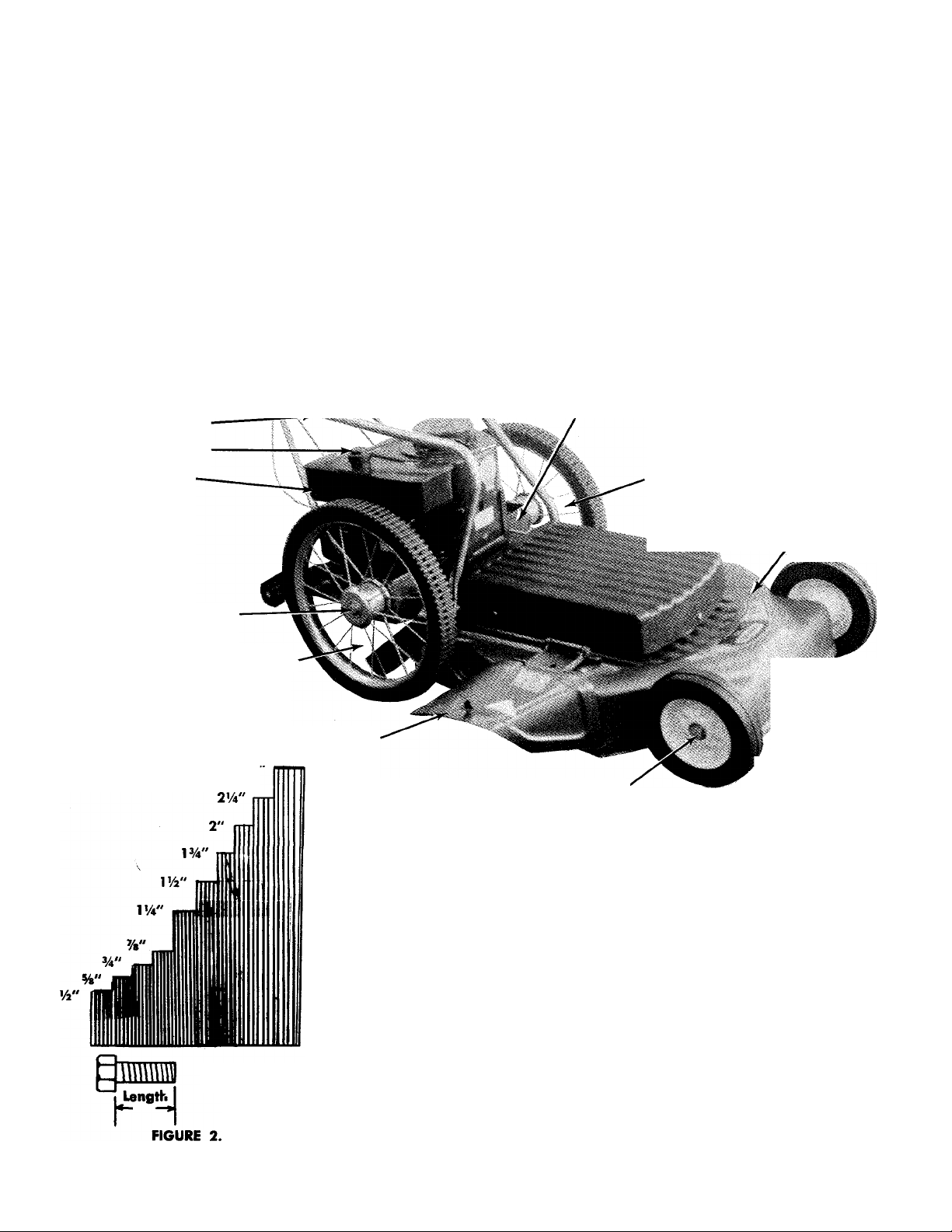
REFERENCE PHOTO FOR ASSEMBLY AND INSTRUCTIONS
Upper Handle (2)
Throttle Control
L
K;-
/
Blade Engaging
Lever (Under Handle ',
Panel)
Throttle Control Cable.
R.H. Brace
Gasoline Filler Cap
Gasoline Tank
Rear Wheel Axle Bolt
Grips (2)
Handle Panel
Lower Handle (One Piece)
L. H Brace
/ X-
Starter Handle
Oil Fill and Drain Left Side of Engine
Rear Wheel Assembly
Shroud
Deck Assembly
Rear Protective Shield Assembly
Chute Deflector Assembly
2'/2
Measure Screws Here
Length
Front Wheel Axle Bolt'
LIST OF CONTENTS IN HARDWARE PACK
(11) He.-: Center Locknuts 14-20 Thread.
(3) He>, Head Bolts 14-20 Thread x 114" Long.
(3) Hex Head Bolts 14-20 Thread xl Vi" Long.
(2) Hex Head Bolts V4-20 Thread x 2Vi" Long.
(2) Slotted Hex Head Screws 8-32 Thread x Vi" Long,
n) Speed Nut.
(1) Truss Head Machine Screw 10-24 Thread x %"
Lonn
(1) Hex I'-ad Bolt %-16 Thread x 1" Long.
(1) Hex head Bolt %-16 Thread x %" Long.
(2) Flat Washers %" I.D.xl54" O.D. x 5/32 Thick.
(1) Flat Washer V4" I.D. x’/2" O.D. x 1/16" Thick
(1) Flat Washer Vi" l.D. x O.D. x 1/32" Thick.
Refer to figure 4.
Front Wheel Assembly
Page 5
INDEX
Safe Operation Practices
Guarantee
Maintenance Agreement
Customer's Responsibilities
Set-Up Instructions------------------------------------------------------ 3
Reference Photo
Bolt Measurement Chart
List of Contents in Hardware Pack
Index
Assembly Instructions______________________________5
Controls ________________________________________ 10
Operation
To Start the Engine
Efficient Operation
Adjustment
Mower Lubrication
Engine Lubrication ---------------------------------------------------- 16
Engine Maintenance---------------------------------------------------- 17
Carburetor Adjustment
Storage Instructions
Engine Service----------------------------------------------------------
Trouble Shooting Chart------------------------------------------------19
______________________________________
______________________________________
___________________________
---------------------------------
-----------------------------------------------------
------------------------------------------------------
2
11
12
13
15
Exploded Parts Illustration
Parts List of Parts for AAower
Exploded Parts Illustration
Parts List of Parts for Mower
Exploded Parts Illustration
Parts List of Parts for Mower
4
Blade Spindle Detail
Blade Idler Bracket Detail
Belt Idler Reference Photos
Notes __________________________________________ 28
Notes
_______-__________________________________
Exploded Parts lllustretion for Engine
Parts List for Engine
Parts List for Engine
Exploded Parts Illustration for Engine Magneto
Exploded Parts lllustrstion for Carburetor
Exploded Parts lllustrcition for Rewind Starter
How to Order Repair Parts
_________________________
______________________
________________________
_______________________
_________________________
_______________________
__________________________
________________________
____________
______________________________
______________________________
________
__________
________
_________________________
20
21
22
23
24
25
26
27
29
30
31
32
33
34
35
36
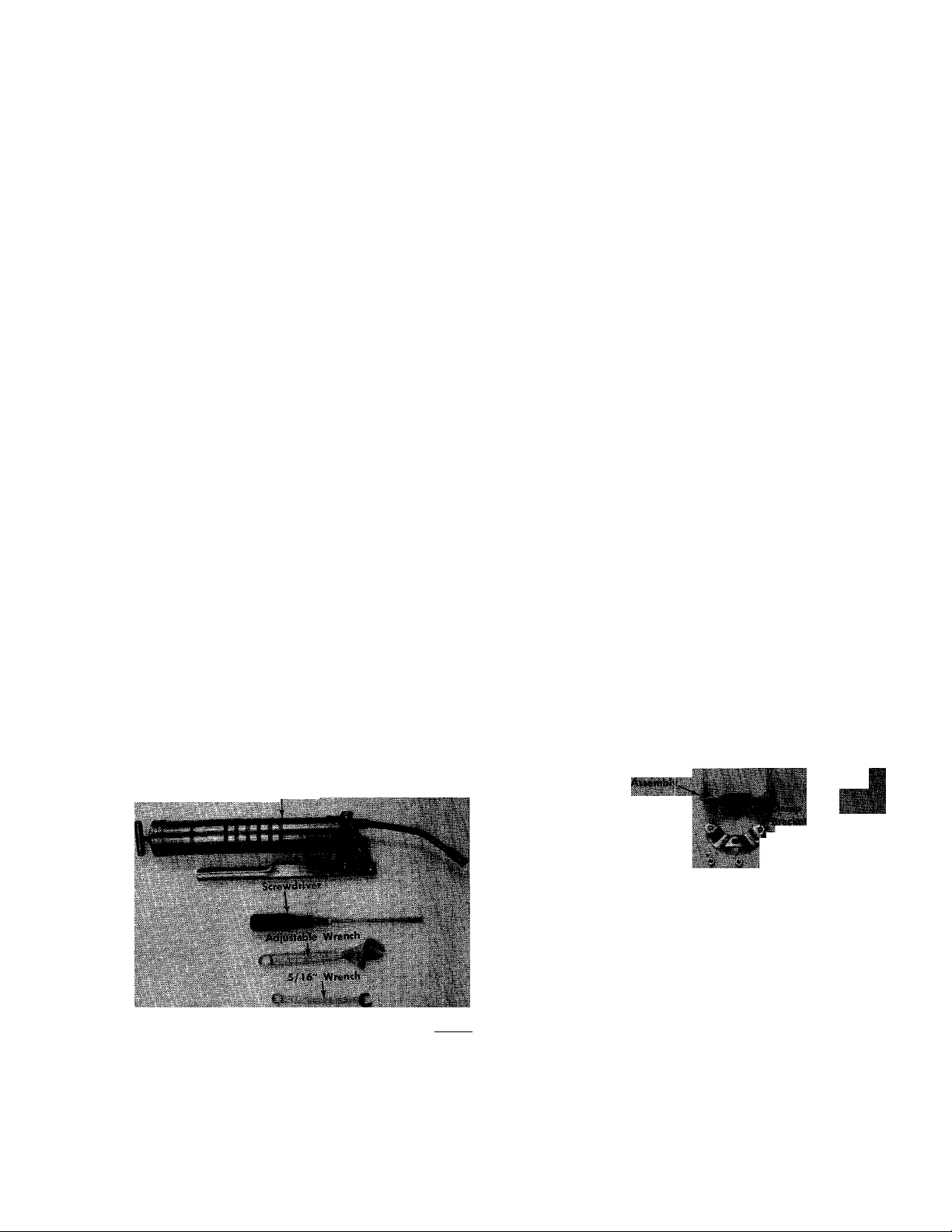
Grease Gun
FIGURE 3. TOOLS REQUIRED
ASSEMBLY INSTRUCTIONS
Lockojr Hriclul
iLoekoul Lever '■*
MmSE
lAuumbly
I Nat Washer_j
. , M- Mr 10-24XH" Hex Hd. Bolt W-20ji;!
|Hpx Hd
IPX nd ^ Hex Hd Biilt_
!•» ^ dl * « •
FIGURE 4. LOOSE HARDWARE
NOTE: Reference to right hand and left hand of your
unit is from the operator's position.
Sletipd Hex tid
cr 8-32 X'4'
S t r- ,,
I D X '-s" O.D. ■ Truss!
• Truss Hd Mach^Scr Throtffe Clamp
SSL ^ 1 I Hex Hd bell .-20 x
nhei^*^ 16 X . af * •
'A" O.D.
- ^Hex Cenfet'LiiekV
^ Nut Lij-aa ii
IW".
Page 6
Lower Handle
(2) Flatwashers
%" I.D. X 1 'A" O.D.
Hex Hd. Bolt—
--16x 1'
FIGURE 5 LOWER HANDLE ASSEMBLY
Step 1.
Step 2.
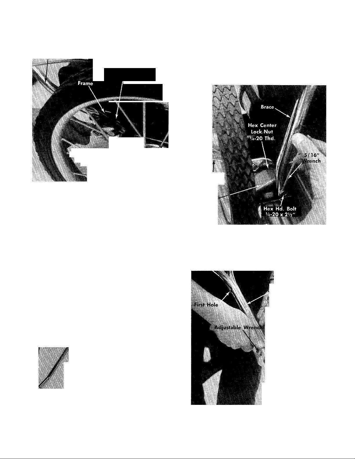
a. Place the right hand brace in position on frame
and secure with one (1) Hex Hd. Bolt 14-20 x 2Vi".
Refer to figures 6 and 7.
NOTE: Do not tighten.
Adjustable
Wrench
Fram
a. Place the lower handle in position on the frame.
b. Place two (2) flat washers %" I.D. x 114" O.D.
between the handle and frame only on the right
hand side. See figure 5.
c. Secure the right hand side of lower handle with
one (1) Hex Hd. Bolt %-16x 1" Long.
NOTE: Just run bolt in two or three threads. Do
not tighten.
d. Secure the left hand side of lower handle with
one (1) Hex Hd. Bolt %-16x %" Long.
NOTE: No washers are required for the left hand
side. Again just run the bolt in two or three
threads. Do not tighten.
^ ■ left Hand Brace
X.
Right Hand Brace
FIGURE 7. BRACE ASSEMBLY
b. Place the left hand brace in position on frame
and secure with one (1) Hex Hd. Bolt 14-20 x 2V2”.
Refer to figures 6 and 7.
NOTE: Do not tighten.
2) Upper Handles
Hex Center Lock Nut
U-20 Thd.
-5/16" Wrench
'Second Hole
FIGURE 6. RIGHT AND LEFT HAND BRACE
Hex Hd Bolt 14-20 x l’/4"
4'.
FIGURE 8. UPPER HANDLE ASSEMBLY
c. Place the two (2) upper handles together using
the second hole. See figure 8.
Page 7

d. Secure the two (2) upper handles together with
one (1) Hex Hd. Bolt %-20xl%" and one (1)
Hex Center Lock Nut '/4-20 Thd.
NOTE: Do not tighten. See figure 8.
e. Place the two (2) upper handles assembled in
position with the lower handle. See figure 9.
FIGURE 10. THROTTLE CLAMP ASSEMBLY
Step 3.
FIGURE 9. HANDLE AND BRACE ASSEMBLY
f. Place a bolt, regardless of length, in the top hole
of the lower handle to help hold handle in po
sition when working.
g. The right and left hand braces have five (5) hole
locations for mounting the braces to the lower
handle. The reason for having five (5) hole lo
cations is so that you may adjust the handle
height to suit you.
h. Upon selecting the desired height of handle,
secure with one (1) Hex Hd Bolt ’^-20xl'/i"
and one Hex Center Lock Not '^-20 Thd.
NOTE: Use the bottom hole of lower handle
only. See figure 9. Do not tighten.
a. Place the speednut on the throttle clamp. See fig
ure 10.
Throttle Clamp
with Speed Nut
Upper Handles %
«Hex Hd. Bolt
'4-20x1'/2"
stable Wrench
Hex Center Lock Nut
'/4-20 Thd.
FIGURE 11. THROTTLii CLAMP ASSEMBLY
b. Place the throttle clamp with speed nut in po
sition on upper handle.
NOTE: Be sure the speed nut is towards the top
of handle. See figure 11.
c. Secure the throttle clamp with one (1) Hex Hd.
Bolt 14-20x1 VS" Long end one (1) Hex Center
Lock Nut 14-20 Thd.
Page 8
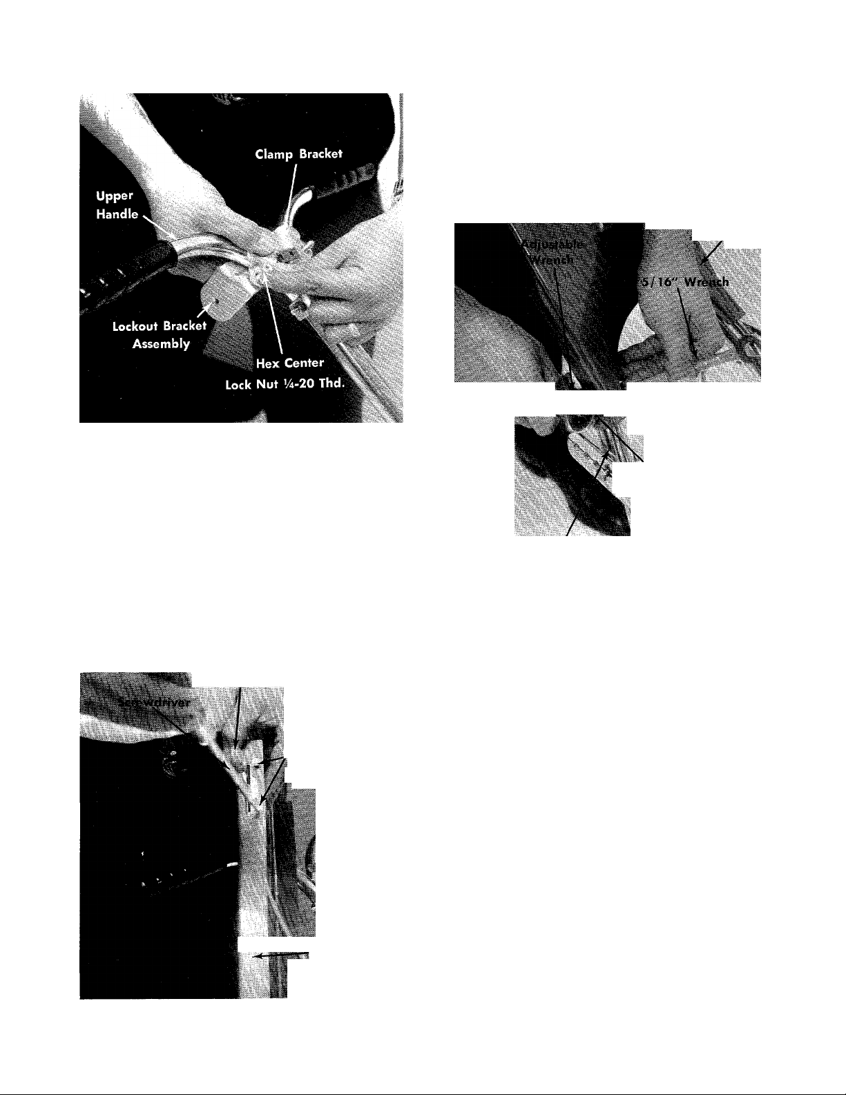
FIGURE 12. LOCKOUT BRACKET ASSEMBLY
d. Place the lockout bracket assembly under the
"T" portion of the upper handle with the bolt
ends facing up. See figure 12.
e. Place the clamp bracket over the bolt ends in the
lockout bracket assembly and secure with three
(3) Hex Center Lock Nuts Vi-20 Thd. See figure
12. Tighten nuts tight.
b. Secure two (2) Self Tapping Screws 8-32 x ’/2"
holding throttle control to handle with a screw
driver tightly. See figure 13.
Step 5.
a. Place the handle panel with throttle control at
tached in position on handle assembly. See fig
ure 14.
Handle Panel
Si
Hex Center Lock Nut
'4-20 Thd.
Hex Hd. Bolt
V4-2OX Vy Lg.
Handle Assembly
FIGURE 14. HANDLE PANEL ASSEMBLY TO HANDLE
Step 4.
a. Start the two (2) self tapping screws 8-32 x ’/2"
in by hand which hold the throttle control to the
handle panel. See figure 13.
Throttle Control
(2) Self Tapping
Screws 8-32 x
Handle Panel
FIGURE 13. THROTTLE ASSEMBLY TO PANEL
Page 9
b. Secure bottom of handle panel to handle as
sembly with two (2) Hex Hd. Bolts Va-2Q x 1 '/2"
and two (2) Hex Center Lock Nuts '/4-20 Thd.
See figure 14.
c. Secure top of handle panel to speed nut with
one (1) Truss Hd Machine Screw 10-24 x %" Long.
See figure 15.
'russ Hd. Mach. Screw
10-24 X 3s" Lg.
■^7*
-----
Handle
i.
FIGURE 16 DRIVE PINION CLEARANCE
|W/S$HtR BOLTS
li LOCKOUT
lever
FIGURE 15. HANDLE PANEL ASSEMBLY TO HANDLE
Step 6.
a. Tighten all nuts and bolts on handle assembly,
braces and handle to frame, securely with
wrenches.
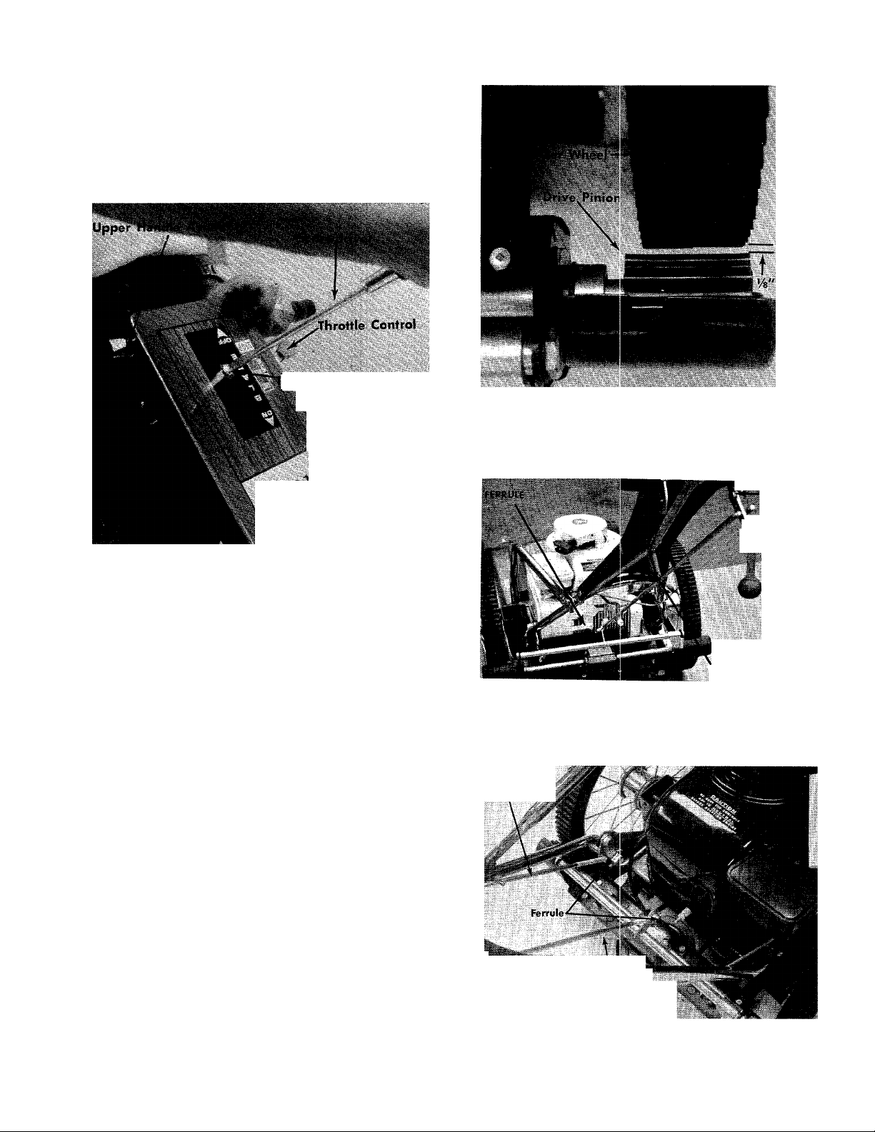
Step 7.
Assemble one of the control rods and lockout
levers to the self-propelling mechanism with
the ferrule (G) and washer (H) at the bottom
and washer (F) and nut (E) on the lockout lever
as shown in figures 17 and 18.
NOTE
Both lockout levers and rods are the
same. Be sure the control rod is on the
Left Hand side of the lockout lever as
shown in figure 17.
CAUTION
Check the distance between the drive
pinions and the r^ar tires. When the
lockout lever is disengaged, the pinion
should be no more than 1/8" from the
rear tire. Adjust the rod in the ferrule
if necessary to obtain the 1/8" distance.
See figure 16.
FIGURE 17.SELF-PROPEL CONTROL ASSEMBLY
Blade Control
Rod
Self-Propel Control Rod
SELF-PROPEL
CONTROL ROD
FIGURE I B. FERRULE ADJUSTMENT
Page 10
Step 7. Assemble the other control rod and lockout
lever to the pivot lever on the lower Left Hand
side of the mower with ferrule and washer.
Assemble the lockout lever to the upper han
dle with washer and nut as shown in figures
18 and 19.
NOTE
With the blade lockout lever in the dis
engaged position, adjust the rod in the
ferrule so that there is just enough
resistance to hold the blade lockout lev
er in place.
BLADE rCNTKI 1
LOCKOUT I EVER
art Position Away from Operator^
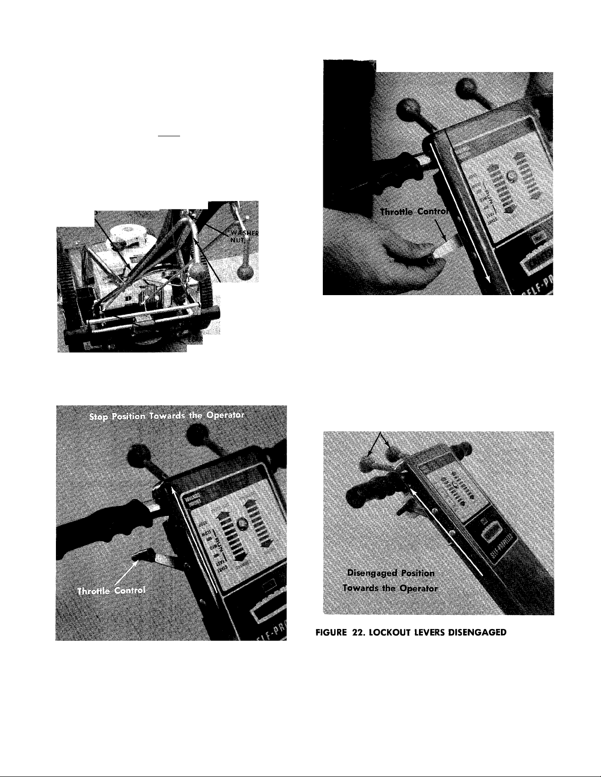
FIGURE 21. THROTTLE CONTROL START POSITION
ULE
WASHit
FIGURE 19. BLADE CONTROL ASSEMBLY
CONTROLS
2. Figure 21 shows throttle control in the START posi
tion.
Lockout Levers in Disengaged Position
FIGURE 20. THROTTLE CONTROL STOP POSITION
1. Figure 20 shows throttle control in the STOP posi
tion. Throttle should remain in this position any
time the unit is not in use or when any mainte
nance is being performed.
Figure 22 shows lockout lever in the OFF position
(Disengaged) lever all the way up. Lockout levers
must remain in this position when starting.
10
Page 11
OPERATION
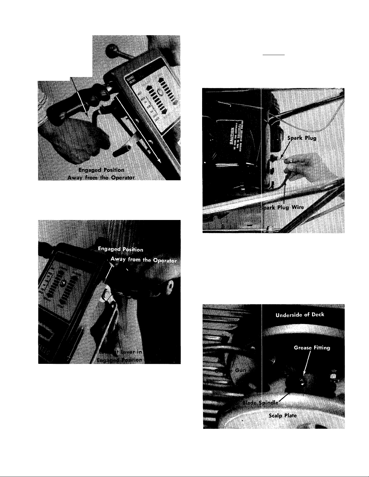
CAUTION
Lockout Lever
Engaged Position
FIGURE 23. DRIVE MECHANISM ENGAGED
Stop the engine and disconnect the
spark plug wire from the spark plug
before making any adjustments. See
figure 25.
FIGURE 25. SPARK PLUG WIRE BEING REMOVED
1. Blade Spindle Assembly—The blade spindle as
sembly is equipped with a grease fitting. Use grass
discharge chute for access to the fitting located un
der the deck. Use multi-purpose grease. Lubricate
PRIOR to initial use and every 25 hours thereafter.
See figure 26.
CAUTION: Be sure spark plug wire is disconnected
and grounded. See figure 25.
FIGURE 24 BLADE ENGAGED
4. Figures 23 and 24 show lockout levers engaged and
locked over center.
FIGURE 26. INITIAL LUBRICATION OF BLADE SPINDLE
ASSEMBLY
11
Page 12

2. Service engine with clean fresh regular gasoline.
3. Service engine with SAE 30 weight motor oil. Fill
oil fill opening to overflow. See figure 27.
TO START THE ENGINE
1. Be sore the engine has been serviced with the pro
per oil and fuel.
2. Move the lockout lever to the DISENGAGED posi
tion.
3. Move the throttle control lever to the START posi
tion.
4. Place one foot on the left side of the deck. See fig
ure 28.
5. Grasp the starter handle and pull out sharply and
hold it in the out position. (Do not let cord snap
back.) The cord should not be pulled out more
man about two feet. If the engine fails to start, al
low the cord to wind back into the housing, then
' pull out sharply again. Refer to figure 28.
K
Starter Handle
FIGURE 27. OIL FILL LOCATION
4. Move the lockout lever to the DISENGAGED posi
tion. (All the way towards the operator.)
5. Move the throttle cotnrol lever to the START posi
tion. (All the way forward.)
6. Put blade into motion by moving blade control
handle to ON position.
To engage the blade with the engine running:
a. Move the throttle control lever to FAST position.
b. Engage the blade engagement handle SLOWLY.
c. Adjust engine speed.
7. Appropriate clothing should be worn when cutting
brush or heavy weeds. Safety shoes and safety
glasses are highly recommended.
8. The operation of any powered outdoor equipment
can result in foreign objects being thrown into the
eyes, which can result in severe eye damage. Al
ways wear safety glasses or eye shields before com
mencing power tool operation. We recommend
Wide Vision Safety Mask for over spectacles, or
standard safety glasses... available at Sears re
tail or catalog stores.
^I^One Foot On Left Side of Deck
FIGURE 28. STARTING
EFFICIENT OPERATION
CAUTION
Stop the engine and disconnect the
spark plug wire from the spark plug
before making any adjustments.
Deck—The underside of rpower deck should be
cleaned after each period of use as grass clippings,
leaves, dirt and other matter accumulates. This
accumulation of grass clippings, etc., is undesirable
as it will invite rust and corrosion and may cause
an uneven discharge of grass clippings at next
cutting.
12
Page 13

2. The deck may be cleaned by tilting the mower
backward or on its side and scraping clean with a
suitable tool or by washing with a stream of wa
ter from a garden hose.
CAUTION
Do not direct the stream of water at a
hot engine as damage to the engine
may result.
3. For best results do not cut wet grass because it tends
to stick to the underside of the mower, thus pre
venting proper discharge of grass clippings. If wet
grass must be cut, reduce walking speed to help
distribute the clippings more effectively.
New grass should be treated as wet grass, other
wise a normal walking speed is about the right
pace for efficient mowing.
The best mowing pattern is one that allows the
clippings to discharge towards the uncut part of
the lawn. This permits recutting of the clippings
to further pulverize them. When cutting high
weeds, discharge towards cut portion then recut
at right angle to first direction.
Lawns should be cut in fall as long as there is
growth.
WARNING
1
1. The mower should not be operated without the
entire grass catcher or chute deflector in place.
2. The mower should not be operated without the
protective shield on the rear of the deck in place.
Lower Support
ive Hole .Locations
Lowe^^aiidle
/
FIGURE 29. HANDLE ADJUSTMENT
2. Remove hex lock nut holding the lockout lever in
position.
3. Remove the hex head bolts and nuts holding the
lower supports to lower handle.
4. Position handle for desired height and reassemble
lower supports to the lower handle. See figure 29.
CAUTION
Stop the engine and disconnect the
spark plug wire from the spark plug
before making any adjustments.
IMPORTANT
After striking a foreign object, stop the
engine (motor), remove wire from spark
plug. Thoroughly inspect the mower for
any damage and repair the damage be
fore restarting and operating the
mower.
ADJUSTMENT
CAUTION
Stop the engine and disconnect the
spark plug wire from the spark plug
tefore making any adjustments.
1. Handles may be adjusted by changing the posi
tion of the lower support mounting holes. When
this change is made, it may also be necessary to
check the adjustment of the control rod. See figures
29 and 30.
1. Lockout rod adjustment is made as shown in figure
30.
Lockout Rod
FIGURE 30. LOCKOUT ROD ADJUSTMENT
13
Page 14

2. Remove the hex lock nut holding the lockout lever
in position.
3. Turn the lockout rod and lever in or out of the fer
rule until the lockout lever lines up with the lock
out bracket.
4. Secure lockout lever in position with hex lock nut.
CAUTION
Stop the engine and disconnect the
spark plug wire from the spark plug
before making any adjustments.
1. Cutting height adjustment is made by removing
and moving axle bolts to the desired positions. All
axle bolts must be mounted in the same relative
position to the deck. When wheels are mounted to
the deck, the crown shape washers must be assem
bled with the crown away from the deck. This is
necessary to prevent the axle bolts from loosening.
Refer to figures 31, 32 and 33.
FIGURE 32. REAR WHEEL HEIGHT ADJUSTMENT
Front Wheel
FIGURE 31. FRONT WHEEL HEIGHT ADJUSTMENT
2. Upon reassembling the rear wheel, be sure the
crown washer is positioned in the inner frame
bracket. See figure 32.
Rear Wheel
FIGURE 33. CROWN WASHER LOCATION FOR REAR
WHEEL
CAUTION
Axle Bolt
Stop the engine and disconnect the
spark plug wire from the spark plug
before making any adjustments.
14
Page 15

1. Throttle Control—If throttle adjustment becomes
necessary, the throttle control wire may be reset
as follows:
a. Loosen, but do not remove, screw securing throt
tle control wire assembly at engine.
b. Move throttle control lever on handle to START
position.
c. Move lever to which control wire is fastened to
engine to full START position. Retighten screw
to secure throttle control wire assembly. See fig
ure 34.
FIGURE 35. REAR WHEEL LUBRICATION
CAUTION
Stop the engine and disconnect the
spark plug wire from the spark plug
before making any adjustments.
Throttle Conduit
FIGURE 34. THROTTLE ADJUSTMENT
MOWER LUBRICATION
CAUTION
Stop the engine and disconnect the
spark plug wire from the spark plug
before making any adjustments.
1. Wheel bearings are ball bearings front and rear.
Lubricate at least once a season with SAE 30 weight
motor oil.
a. Front wheels to be oiled at the axle bolt.
b. Rear wheels to be oiled at oil caps in rear wheel.
See figure 35.
2. Throttle—Periodically lubricate throttle control lever
and entire length of throttle wire assembly with
a few drops of SAI: 30 engine oil for ease of oper
ation.
CAUTION
Stop the engine and disconnect the
spark plug wire from the spark plug
before making any adjustments.
3. Friction point between idler bracket assembly and
deck should be greased once each season with a
multi-purpose grease. See figure
CAUTION
Stop the engine and disconnect the
spark plug wire from the spark plug
before making any adjustments.
4. Protective Shield—The pivot points on the protective
shield should be lubricated periodically with oil
to prevent any rust or binding up.
CAUTION
Stop the engiine and disconnect the
spark plug wire from the spark plug
before making any adjustments.
15
Page 16

5. Blade Spindle Assembly
The blade spindle assembly, located on the underside
of the mowing deck, is equipped with a grease fitting
Use grass discharge chute for access to the fitting lo
cated under the deck. Use multi-purpose grease. Lubri
cate prior to initial use and every 25 hours thereafter.
See figure 36.
CAUTION
ENGINE LUBRICATION
CAUTION
Stop the engine and disconnect the
spark plug wire from the spark plug
before making any adjustments.
Be sure spark plug wire is disconnected
and grounded.
6. Gear Box
Check lubricant in the self-propelled drive gear box.
This must be maintained half full at all times and
should be checked after each 25 hours of operation.
The gear box is packed at the factory with Alduralube
Heavy or Temprite No. 2. It is suggested that this or an
equivalent type and quality fibrous high heat wheel
bearing grease be used in maintaining this mechanism.
Grease can be ordered by part number 727-111. Hori
zontal bronze bearings under the self-propelled drive
mechanism should be lubricated with SAE 30 engine
oil. Refer to figure 37.
1. Position equipment so that engine is setting level.
Remove oil filler plug. See figure 38.
FIGURE 38. OIL FILL LOCATION
FIGURE 37. GEAR BOX LUBRICATION
7. Chute Deflector—The torsion spring and pivot point
should be lubricated periodically with oil to prevent
any rust or binding up. Deflector must work freely.
2. Pour oil into opening which you removed the oil
filler plug from.
3. During initial "Break-in" period oil level should
be watched closely.
Oil . . . Use the following:
Summer—Above 32° F—SAE 30 (SAE 10W30 is
an acceptable substitute).
Winter-Below 32°F-SAE 5W20 (SAE 10 or
5W30 are acceptable subsitutes).
Winter-Below 0°F Only—SAE 1OW with 10%
kerosene.
4. Change oil first two (2) hours of operation and
check oil level every five (5) operating hours or
each time equipment is used.
5. Change oil every twenty-five (25) operating hours
or sooner if equipment is operated in extremely
dusty or dirty conditions.
6. Oil can be changed by removing the oil drain plug
located on the right hand side of the engine. See
figure 39.
16
Page 17

7. Tip mower on its right hand side and remove the
oil drain plug.
FIGURE 39. OIL DRAIN LOCATION
ENGINE MAINTENANCE
NOTE
Always tip engine toward oil drain hole.
Be sure oil drains completely.
Replace oil drain plug and refill with oil as di
rected on page 1, or engine nameplate.
3. CHECK OIL every nve (5) operating hours or each
time equipment is used.
a. If engine has dip stick, keep oil level at mark
indicated by adding if necessary.
4. CLEANING ENGINE—This is an air-cooled engine
which operates most efficiently when the cooling
fins are clean.
Clean cylinder fins .tnd underside of tank or housing
thoroughly of all accumulated grass and debris.
5. AIR CLEANERS-
a. Polyurethane T>pe—Serviceable. Clean element
every ten (10) hours or oftener if engine runs
rich and emits black smoke from the exhaust.
Service by removing air cleaner cover. Remove
polyurethane element and wash in detergnt and
water solution by squeezing similar to a sponge.
Squeeze out cleaning solution. Re-oil element
by applying generous quantity of oil to sides
and open ends. Squeeze to distribute oil and to
remove excess oil. Reinstall element and air
cleaner cover as illustrated in figure 40.
CAUTION
Stop the engine and disconnect the
spark plug wire from the spark plug
before making any adjustments.
To obtain long life and trouble-free service from your
engine, certain normal maintenance must be per
formed as outlined below:
1. Check unit on which engine is mounted. Hard start
ing can result if blades are loose, belts or chains
too tight, etc. Periodically check bowden wire con
trols. If the wire has loosened it may not put the
carburetor on full choke when starting or open the
throttle wide enough for the RUN or FAST position.
2. Change oil in crankcase after first two (2) hours of
operation. Then, follow instructions outlined un
der OIL, page 16.
CAUTION
Disconnect high tension wire at spark
plug to prevent accidental starting of
engine. Unscrew oil drain plug located
on side of engine (figure 1).
Element
Housing
Sci'een
^'] Bracket
.Attaching
Screw
Element
FIGURE 40.
17
Page 18

CARBURETOR ADJUSTMENTS STORAGE INSTRUaiONS
Do not make unnecessary adjustments. Factory set
tings are correct for most applications. If adjustments
are needed, proceed as follows:
1. Close power adjusting needle (figure 41 or figure
42) by turning to right (clockwise). Close finger
tight only. Forcing will cause damage.
2. Open one turn (counterclockwise).
3. Close idle adjusting needle (figure 41 or figure
42), by turning to right (clockwise). Close finger
tight only. Forcing will cause damage.
Power Drain
Adjusting
Float Feed Carburetor
FIGURE 41.
4. Open one and one-half turns (I'/a) counterclock
wise (figure 41 or figure 42).
5. Start engine. Follow starting instructions.
6. With throttle open (carburetor control at RUN or
FAST position), adjust power adjusting needle one-
eighth ('/s) turn at a time forward or backward un
til engine runs smoothly. If engine tends to stall
under load, enrich slightly (counterclockwise).
Diaphraghm Carburetor
Power
Adjusting
FIGURE 42.
In event engine is to be stored for any length of time
(30 days or more) or at the end of mowing season, pre
pare as follows:
1. Drain gas tank completely by removing fuel line
at the carburetor or fuel tank, whichever is easier.
CAUTION
Drain into container outdoors away
from fire or flame.
2. DRAIN CARBURETOR.
Drain by pressing upward on bowl drain (figure 7).
3. Inside protection of engine for storage is performed
by removing spark plug and pouring one ounce
of SAE 30 oil through spark plug hole into cylinder.
Crank engine without starting several times to
spread oil over cylinder walls.
IMPORTANT: A yearly checkup or tuneup by the SEARS
Service Department is a good way of ensuring that
your rotary mower will provide maximum perform
ance for the next season.
Store the rotary mower in a protected area and cover
the unit for additional protection.
ENGINE SERVICE
Unless the operator is fully qualified to make engine
adjustments and repairs, it is recommended that such
work be done by technicians trained to work on
rotary mower type gasoline engines.
The Repair Parts section of this manual contains a list
of engine replacement parts and illustrations to assist
the trained technician in making repairs and ordering
proper replacement parts.
The following chart. Trouble Shooting, is provided as
a guide for correcting minor problems when the trou
ble is known.
7. Hold throttle lever closed or move carburetor con
trol to IDLE or SLOW position and adjust idle ad
justing needle until engine runs smoothly, pro
ceeding as in step 6 above.
8. Allow several seconds between each adjustment
when performing either step six (6) or seven (7)
to allow engine to react to new setting.
9. Maximum engine speeds are preset at factory and
should not be changed except by a qualified serv
ice station repairman who has the necessary equip
ment.
18
Page 19

TROUBLE SHOOTING CHART
CAUTION: ALWAYS DISCONNECT SPARK PLUG BEFORE ATTEMPTING ANY REMEDY.
TROUBLE
Engine fails to start.
Hard starting or loss of
power.
LOOK FOR
Blocked fuel line or
empty gas tank.
Defective spark
plug.
Throttle setting.
Loose connections Spark plug wire loose.
Dirty air cleaner.
Carburetor improp
erly adjusted.
Clean fuel line; check fuel supply.
Spark plug lead wire disconnected.
Faulty spark plug—spark should jump gap between control
electrode and side electrode. If spark does not jump, re
place spark plug.
NOTE: Use insulated pliers 1o hold the spark plug wire.
Throttle control lever not in the starting position.
Remove air cleaner and clean as outlined in paragraph
Engine Maintenance.
Review paragraph Carburetor Adjustment.
REMEDY
Excessive vibration.
Unit fails to propel
itself.
Unit fails to discharge
grass.
Engine overheats.
Bent or damaged
blade spindle.
Loose parts.
Drive belt loose or
defective.
Lockout rod adjust
ment.
Discharge chute
clogged.
Foreign object
lodged in deck.
Obstructions in air
passages.
Grass and dirt in
engine shroud.
Stop engine immediately; tighten all bolts and make all nec
essary repairs. If vibration continues, have the unit serviced
by a competent repairman.
Stop engine immediately; tighten all bolts and make all
necessary repairs.
Adjust drive belt; replace if defective.
Review paragraph on Adjustments, page 13.
Clean discharge chute and inside of deck.
Remove object from deck. See CAUTION following step 1 in
paragraph Operation.
Remove any obstruction from air passages in shroud.
Clean cooling fins.
Oil level.
Fill crankcase to proper oil level.
19
Page 20

CRAFTSMAN HI WHEEL SELF-PROPELLED ROTARY MOWER MODEL 247.88110
K>
o
(D
TJ
Q
■ o
Q
</)
Page 21

CRAFTSMAN HI WHEEL SELF-PROPELLED ROTARY MOWER MODEL 247.88110
REF.
NO.
1 712-107
2
3 9354
4
5 7889
6 8373
7
M
8 8376
9
10 712-107
11
12
13
14
15 9362
16
17
18 738-234
19
PART
NO.
Hex Center Locknut 14-20 Thd.
8378 Clamp Bracket
Upper Handle (2-Req'd.)
720-157 Grip
Plastic Ball
Lockout Lever Ass'y- with Plastic
711-180 Control Rod
Lockout Bracket Ass'y-
736-108 Flat Washer .510" I.D. x .75"
Hex Center Locknut 14-20 Thd.
712-107
710-106
710-606 Hex Scr. 1/4-20 X 1.50" Lg.*
712-107 Hex Center Locknut 14-20 Thd.
8327
712-130 Hex Inserted Lockout %-l 6 Thd.
9372
Hex Center Locknut 14-20 Thd.
Hex Scr. 1/4-20 X 1.25" Lg.*
Lower Handle
Lower Handle Support—L.H.
Shoulder Scr. .500" Dia. x .295
Pivot Bracket
DESCRIPTION
Ball
O.D. X .033
REF.
NO.
20
21
22
23
24
25
26
27
28
29
30
31
32
33
34
35
36
37
38 711-180
PART
NO.
711-180
711-179 Adjustment Ferrule
710-253
710-102
712-107
11991
736-119.
712-123
11990-347
710-473
746-171
712-526
710-473
752-404
746-128
710-606
712-526 Speed Nut #10-24
Control Rod
Hex Scr. %-16 X .62" Lg.*
Hex Scr. 1/4-20 x 2.50" Lg.*
Hex Center Locknut ’/4-20 Thd.
Lower Handle Support—R.H.
Spring Lockwasher 5/16" Scr.*
Hex Nut 5/ 16-24 Thd.*
Handle Panel
Truss Mach. Scr. 10-24 x .50"
Throttle Control Ass'y.—Comp.
Speed Nut 10-24
Truss Mach. Scr. 10-24 x .50"
Engine Model No. V60-70259H
Cable Clip for %" Tubing
Hex Scr. 1/4-20 X 1.50" Lg.*
7861
Clamp Bracket
Control Rod
DESCRIPTION
Lg.*
Lg.*
* Standard Hardware Items—May Be Purchased Locally.
Page 22

CRAFTSMAN HI WHEEL SELF-PROPELLED ROTARY MOWER MODEL 247.88110
(D
TD
Q
T3
Q
</)
Page 23

CRAFTSMAN HI WHEEL SELF-PROPELLED ROTARY MOWER MODEL 247.88110
REF.
NO.
1 710-121
2 736-114
3
4
5
6
7
8
9
10
11
12
13
14
15
M
u
16
17
18
19
20
21
22
23
24
25
26
'¿/
28
29
30
31
32
33
34
35
36
PART
NO.
Hex Scr. ’/2-20 X .75" Lg. Special
Internal Lockwasher ’/2" Scr.*
748-108 Flange Bearing .503" I.D.
748-136
7146
748-110 Flange Bearing .630" I.D.
8187-347 Gear Box Cover
710-148 Hex Washer Hd. F-Tapp. Scr.
748-135
711-180 Control Rod
711-179
8331
8189 Gear Box
710-289
736-329
710-252
8348
748-110 Flange Bearing .630" I.D.
710-421
715-247
711-415 Clevis Pin .375" Dia.
736-300
714-121
736-329
712-287
1100/-J4/
711-169 Collar %" I.D.
736-108
8772-347
712-287
736-329
748-226
8774-347
714-229
Pinion Gear .50" I.D. 14 Teeth
Pinion Shaft
Bevel Gear .62" I.D.—28 Teeth
Adjustable Ferrule
Pull Bar Assembly
Hex Scr. ’/4-20 X .50" Lg.*
Spring Lockwasher ’A" Scr.*
Hex Scr. '/4-20 X .75" Lg.*
Drive Shaft
Set Scr. 5/16-18 X .25" Lg.*
Spring Pin Spirol 3/16" Dia. x
7120
Nylon Pinion
Cotter Pin 5/32" Dia. x 1.00" Lg.*
Spring Lockwasher ’A" Scr.*
Stop—Drive Plate
Spring Lockwasher ’A" Scr.*
9927
Sheave Ass'y-—5.50 x .50
DESCRIPTION
#8-32 X .38" Lg.*
1.00" Lg.
Flat Washer .385" I.D. x .87" O.D.
X.06
Hex Nut ’A-20 Thd.*
Flat Washer .510" I.D. x .75" O.D. x
.033
Belt Guard
Hex Nut ’/4-20 Thd.*
Hex Flange Bearing .503" I.D.
Bottom Frame Ass'y-
#2 Woodruff-—Key 3/32 x ’/2" Dia.
Hardened
REF.
NO.
37 11996-347 Spacer Plate Ass'y.
38 710-409
39 754-121 "V"-Belt ’/2" X 31.8" Lg. (Drive
40 756-205
41
42
43 710-152 Hex Scr. %-24 x 1.00" Lg. Heat
44 710-528 Hex Scr. 5/16-18 x I’A" Lg.*
45 736-119 Spring Lockwasher 5/16" Scr.*
46
47 8324-347
48 736-119 Spring Lockwasher 5/16" Scr.*
49 712-267
50 8298 Idler Bracket Ass'y. with Brake Shoe
51
52
53
54
55 9373 Control Rod
56 732-137 Extension Spring
57
58
59
60
61
62
63
64
65
66
67
68 736-105
PART
NO. DESCRIPTION
Hex Scr. 5/16-24 x 1.75" Lg.*
Belt)
Two Step Engine Pulley
736-235
736-217 Spring Lockwasher %" Scr. Heavy
712-130 Hex Inserted Locknut %-16 Thd.
756-370
736-300 Flat Washer .385" I.D. x .87" O.D.
712-158 Hex Center Locknut 5/16-18 Thd.
732-158 Blade Tension Spring
754-109 "V"-Belt ’/2 X 43" Lg. (For Blade)
738-234
736-108 Flat Washer .510" I.D. x .750" O.D.
712-922
736-921 Spring Lockwasher ’/2" Scr.*
8279-347 Frame Ass'y.—Comp.
736-147
10523-347
Flat Washer .406" I.D. x 1.25" O.D.
X.164
Duty
Treated
Belt Guard
Hex Nut 5/16-18 Thd.*
Idler Bearing Ass'y.
X .06
7353
9371
Belt Clip
Shoulder Scr. .500" Dia. x .295
X .033
Brake Lever
Hex Jam Nut ’/2-20 Thd.
9925 Sheave Ass'y.—4" Dia. (Blade
Spindle)
Extern Lockwasher #10
Top Drive Frame Ass'y.
Belleville Washer %" I.D.
^Standard Hardware Items—May Be Purchased Locally.
Page 24

'//■
Page 25

CRAFTSMAN HI WHEEL SELF-PROPELLED ROTARY MOWER MODEL 247.88110
REF.
NO.
1
2
3 8279-347
4
5 710-567
6 736-329
7 11446-347 Deck Assembly
8
9 713-132
M
(II
10 741-113 Ball Bearing .504" I.D. x 1.38" Dia.
11
12 11141-347
13 732-253 Torsion Spring
14
15
16 711-555
17
18
19
20
21
PART
NO.
710-117
710-158
710-209
11197-347
738-114 Shoulder Scr. .498" Dia. x 4.755"
726-106 Push Nut ’/4" Rod
11130-347
10769
734-438 16" Rear Wheel Ass'y. Comp.
734-180 16" Rear Wheel—Less Tire
734-391 Semi Pneumatic Tire 16 x 1.75
741-114 Ball Bearing .504" I.D. x 1.12" Dia.
738-213 Shoulder Scr. .498" Dia. x 1.450"
Hex Scr. 5/16-24 x 1.00" Lg. 22
Heat Treated
Hex Scr. 5/16-24 X 1.25" Lg.*
Frame Ass'y-—Complete
Hex Sems Scr. %-16 x .62" Lg.*
Hex Sems Scr. 14-28 x %" Lg. 27 710-117 Hex Scr. 5/16-24 x 1.00" Lg.
Spring Lockwasher L4" Scr.*
Protective Shield Ass'y.—Comp.
Oil Cap 29
Chute Deflector Ass'y.
Adapter Plate
Pivot Pin
Blade Adapter Kit
DESCRIPTION
Lg.
Gear Tread
Lg.
REF.
NO.
23 736-105
24 712-123 Hex Nut 5/16-24 Thd.*
25
26
28 710-459 Hex Scr. %-24 x 1.50" Lg. Heat
30
31
32
33
34
35 736-119 Spring Lockwasher 5/16" Scr.*
36
37 7805
38 710-473
39 731-230
40
41
42
43
PART
NO. DESCRIPTION
9383-501
736-129 Spring Lockwasher 5/16" Scr.*
742-125 22" Blade
736-217 Spring Lockwasher %" Scr. Heavy
748-189
712-123
736-119
712-123 Hex Nut 5/16-24 Thd.*
11679-347
712-526
770-4447
775-1121
Front Wheel Ass'y. Comp.
Belleville Washer
Heat Treated
Treated
Duty
7919
Scalp Plate
Blade Adapter
Hex Nut 5/16-24 Thd.*
Spring Lockwasher 5/16" Scr.*
8809 Reinforcement Plate
Blade Spindle Ass'y.—Comp.
Truss Mach. Scr. #10-24 x .50"
Lg.*
Blade Spindle Cover
Chute Deflector Ass'y.—Comp.
Speed Nut #10-24
Owners Manual (Not Illustrated)
Model Plate (Not Illustrated)
*Standard Hardware Items—May Be Purchased Locally.
Page 26

BLADE SPINDLE ASSEMBLY 901-7805
2. Zerk Fitting should face Discharge Chute of Deck.
3. Lubricate every 8 to 10 hours with Shell General
Purpose Grease or Equivalent.
BLADE IDLER BRACKET ASSEMBLY DETAIL
Brake Shoe 754-647
Rivet 728-649
BELT WEAR
Belt clips improperly positioned will cause premature
belt wear. The belt clip must completely clear the belt
when the belt is tightened. It should also assist in free
ing the belt from the blade spindle pulley when the
belt is loose. This may be checked by removing the
blade spindle cover.
Bracket Assembly 8298
Idler Bearing 756-370
Hex Lock Nut
>12-372
Belt Clip
7353
26
Page 27

p Must Not Toiiti]^
Where Blade Is
27
Page 28

NOTES:
28
Page 29

NOTES
29
Page 30

TECUMSE H 4 -aCLE ENG INE
MODEL NUMBER: V60-70259H
f-
-----
137
30
Page 31

TECUMSE H 4 -CY CLE E NGIN E
Ref.
No.
Part
No. Part Name
Ref.
No.
MODEL NUMBER: V60-70259H
Part
No.
Part Name
1
33361
2
27652
4 27876B Seal, Oil equivalent)
5 27877A Valve, Intake (Stemdard) (Incl.
27880A Valve, Intake (1/32” oversize)
5
6 27878A
6 27880A
7 27882
8 27881
9 32581
11 33799
12 29783 Pin, Crankshaft gear
13 27884
14
14
14 33314
15
15 33316
15
16 27888
17
18 30682
19
20 28264
21
22 33157
23
24
25
27
28
29
34 27897
35
36
39
43
44
47
48
49
33312
33313
33315
33317
31380B
26073
27893
*30684
31471B
31355
29117
31356
27642
650548
31335
650488
27625
*29673
*28938B
30938A
30939A
Cylinder Assy. (Incl. Nos. 2 &
4)
Pin, Dowel
No. 9)
(Incl. No. 9)
Valve, Exhaust (Standard)
(Incl. No. 9)
Valve, Exhaust (1/32” over- 10-24x1/2
size) (Incl. No. 9)
Cap, Upper valve spring
Spring, Valve
Cap, Lower valve spring
Crankshaft Assy. (Incl. Nos. 12
& 13)
Gear, Crankshaft
Piston & Pin Assembly (Incl. 2
of No. 16) (Standard)
Piston & Pin Assembly (Incl. 2
of No. 16) (.010 oversize)
Piston & Pin Assembly (Inch 2
of No. 16) (.020 oversize)
Ring Set, Piston (StandEird)
Ring Set, Piston (.010 oversize)
Ring Set, Piston (.020 oversize)
Ring, Piston pin retaining
Rod Assembly, Connecting
(Incl. Nos. 18,19 & 20)
Bolt, Connecting rod
Washer, Connecting rod bolt
Nut, Hex, 5/16-24
Lifter, Valve
Camshaft (Compression Release)
Gasket, Mounting flange
Flange Assembly, Mounting
(Incl. Nos. 25, 27, 29, 34, 43,
44 & 110)
Screen, Oil filter
Screw, Slotted hex hd. self
tap., 8-32 X 5/16 washer, 1/4-20 x 11/16
Pump Assembly, Oil
Plug, Pipe
Seal, Oil
Screw, Hex slotted washer hd..
8-32 X 3/8
Clamp, Governor lever
Screw, Hex hd. Sems, 1/4-20 x
1-1/4
Plug, Oil filler (Incl. No. 44)
Gasket, Oil filler plug
Gasket, Cylinder head
Head, Cylinder
Cover, Cylinder head
51 650697
52 33636
53 *27896
54 28423
55
56
57
59
60
61
63 650152
64 650378
65
69
71
82 32181
83 30200
84
87
88
89
90
91
92
93
94 29536
95
96
98
99
101 650489
102
103 31361
104
105
106
109
110
111
112
28424 Element, Breather
28425
27627
650128
*27915
31358
*26756
6201 Screw, Hex hd. cap, 1/4-28 x
29752 Nut, Hex, 1/4-28
*27272
31691
28820
30727
31692
*27930
28269
650696
31588
650561
30884
28277
31823
30669
32582
31357
31707
30668
30591 Gear Assembly, Governor
29193 Ring, Retaining
Screw, Hex hd. cap, 5/16-18 x
2-1/2
Plug, Spark (Champion J-8 or
Gasket, Valve chamber cover
Body Assembly, Breather
Cover, Valve chamber
Tube, Breather
Screw, Fil. slotted hd. Sems,
Gasket, Intake pipe
Pipe, Intake
Screw, Fil. slotted hd. Sems,
8-32 X 3/8
Screw, Fil. hd. Sems, 5/16-18 x
1-1/8
Gasket, Carburetor
7/8
Control Assy., Speed (Incl.
Nos. 161 & 162)
Screw, Slotted hex washer hd..
10-24 X 1/2
Gasket, Air cleaner bracket-tocarbm’etor
Bracket, Air cleaner
Screw, Phil. fil. hd. mach.
Sems, 10-32 x 1/2
Element, Air cleaner
Body, Air cleaner
Gasket, Muffler flange
Muffl(3r Assembly
Screw, Hex hd. cap, 5/16-18 x
2-3/4
Baffle, Blower housing
Plate, Locking muffler
Screw, Phil, hex hd. Sems,
1/4-20 X 5/8
Key, ]?lywheel
Washes, Flat
Screw, Hex hd. Sems with flat-
Link, Governor
Spring, Governor
Rod, Governor (Incl. No. 99)
Link, Governor spring
Lever, Governor
Spacer
Shaft,, Mechanical governor
*Indicates Parts Included in
Gasket Set, Ref. No. 166.
31
Page 32

TECUMSE H 4 -CY CLE E NGIN E
Ref.
No.
Part
No. Part Name
MODEL NUMBER: V60-70259H
Ref.
No.
Part
No.
Part Name
113
114
115
117
118
119
121
122
123
124
126
127
128
129
131
30588A
27793
28942
30622
31752
650128
30688
27275
650490
8116
32584
32387A
32125
590417
29747A
Spool, Governor
Clip, Conduit
Screw & Lockwasher, Slotted
hex.hd., 10-32 x 3/8
Extension, Blower housing
Decal, Air cleaner
Screw, Fil. slotted hd. Sems,
10-24x1/2
Screw, Hex hd. cap Sems,
1/4-20x1/2
Clip, Hi tension wire retaining
Washer, Belleville
Nut, Hex, 1/2-20
Tank Assy., Fuel (Inch No.
127)
Cap, Fuel
Cup, Starter
Screen, Starter cup
Screw, Hex hd. Sems, cap,
5/16-24 X 3/4
134
137
139
141
142
143
149
159
161
162
163
164
165
166
29774
29716
31398
28670
31345
32629A
31324
28468
31342
650549
610689A
631444
590420
33234
Line, Fuel
Screw, Pan hd. P.C.R. with
lockwasher, 1/4-28 x 7/16
Decal, Instruction
Stud, Drive
Plate, Identification
Housing, Blower
Decal, Name & H.P.
Wire, Ground
Spring, Compression
Screw, Speed adjustment, 5-40
X 7/16 fil. slotted hd. mach.
Magneto
Carburetor
Starter, Rewind
Gasket Set (Incl. items
marked*)
*Indicates Parts Included in
Gasket Set, Ref. No. 166.
32
Page 33

MAGNETO NO. 610689A
Ref.
No.
Part
No.
610689A Magneto
1 30555
2 30551
3 30550
4
5
6 30547A Breaker Assembly
7
8 610408 Nut, Terminal
9 29181
33695
30992 Cam, Breaker
610385 Washer, Terminal
Flywheel
Spring, Breaker box dust cover
Cover, Breaker box dust 14)
Gasket, Dust cover
Screw and Washer Assembly,
Breaker
Part Name
33
Ref.
No.
10
11
13
14
15
16
17
18
19
20
Part
No.
610593
30843
30560A
30554
30548A
30545
30561A
30549
29629
31311
Part Name
Screw, Condenser fastening
Tab, Ground terminal
Coil Assembly (Inch Ref. No.
Wire, Ignition lead
Condenser
Core and Plate Group
Stator Assembly
Felt, Cam wiper
Spring, Coil wedge
Clip, Coil locking
Page 34

Ref.
No.
Part
No.
Part Name
Ref.
No.
631444 Carbxiretor 16
Part
No.
631025
Part Name
Bowl & Drain Assy., Float
1 31834 Shaft & Lever Assy., Throttle (Inch No. 17)
2
631279
3 631036
4 650506 Screw, 4-40 x 3/16 18
5 630766
6 650417
7
630973
8 630739
9 631037
10 *630748
Spring, Throttle return 17 27136A
Shutter, Throttle
Plunger Assy., Drain (Inch No.
18)
*27554 Gasket, Drain plunger
Spring, Idle regulating screw 21 27110
Gasket, Bowl-to-body
Screw, Idle regulating 22 *631026 Adjustment Screw Assy., Main
Shaft & Lever Assy., Choke (Inch Nos. 8, 21, 23 & 30)
Washer, Flat 23 *630740
“O” Ring, Adjustment screw
Shutter, Choke 24 *631078 Screw, Idle adjustment
Plug, Welch 25
*631028 Gasket, Bowl-to-body
11 *631027 Plug, Welch 26 631445 Fitting, Fuel inlet
12 *631021
Inlet Needle, Seat & Clip Assy. 30 630738 Spring, Main adjustment screw
(Inch No. 13)
31 630821 Spring, Choke return
13 631022 Clip, Inlet needle 32 631029 Repair Kit (Incl. items
14
15
631023
*631024 Shaft, Float
Float, Carburetor
marked*)
34
Page 35

REWIND STARTER NO. 590420
Ref.
No.
1 590409
2 590410 Retainer, R.H.
3 590411
4 590148
5 590412
6
Part
No.
590420
590413A
Starter, Rewind
Screw, Retainer
Spring, Brake
Dog, Starter
Spring, R.H. dog
Pulley
Part Name
Ref.
No.
7
8
9
10
11 590459 Pin, Centering
Part
No.
590414 Spring & Keeper Assy.
590415 Housing Assy., Starter
590386 Rope, Starter
590387
Handle Assy., Starter
Part Name
Page 36

owners
How to ORDER Repair Parts
The Model Number will be found on a plate attached to your
mower at the right-hand side of the frame. Always mention the
Model Number when requesting service or repair parts for your
22 INCH HI WHEEL SELF PROPELLED ROTARY MOWER.
manual
MODEL NO.
247.88110
Sears
SERVICE
All parts listed herein may be ordered through SEARS, ROEBUCK
AND CO. or SIMPSONS-SEARS LIMITED. When ordering parts by
mail, selling prices will be furnished on request or parts will be
shipped at prevailing prices and you will be billed accordingly.
WHEN ORDERING REPAIR PARTS, ALWAYS GIVE THE FOLLOWING
INFORMATION AS SHOWN IN THIS LIST.
1. The PART NUMBER
2. The PART DESCRIPTION
3. The MODEL NUMBER 247.88110
4. The NAME OF ITEM22 INCH HI WHEEL SELF PROPELLED
ROTARY MOWER
5. ENGINE MODEL NO. V60-70259H
is at
Yoar
SERVICE
wherever Yea
Your Sears merchandise takes on added value when you discover
live or move
that Sears has over 2,000 Service Units throughout the country.
Each is staffed by Sears-trained, professional technicians using
Sears approved parts and methods.
in the U.S.A.
Sold by SEARS, ROEBUCK AJND CO.,
and
SIMPSONS-SEARS LIMITED.
PART NO. 770-4447 PRINTED IN U.S.A. (12-72)
CbicagoJU. 60607
Toronto
UJaA.
 Loading...