

Page 1
OWNER’S
MANUAL
MODEL NO.
247.799620
CRRFTSMflN
9 HORSEPOWER
SELF-PROPELLED
Caution;
Read and Follow
All Safety Rules
and Instructions
Before Operating
This Equipment
SEARS, ROEBUCK AND CO., Hoffman Estates, IL 60179 U.S.A.
CHIPPER-SHREDDER-VACUUM
Assembly
Operation
Customer Responsibilities
Service and Adjustment
Repair Parts
*rinted in U.S.A.
770-0352L 5/96
Page 2

IMPORTANT
THIS SYMBOL POINTS OUT IMPORTANT SAFETY INSTRUCTIONS WHICH, IF NOT FOLLOWED, COULD ENDANGER THE PERSONAL
SAFETY AND/OR PROPERTY OF YOURSELF AND OTHERS. READ AND FOLLOW ALL INSTRUCTIONS IN THIS MANUAL BEFORE
▲
ATTEMPTING TO OPERATE YOUR POWER CHIPPER-MCUUM. FAILURE TO COMPLY WITH THESE INSTRUCTIONS MAY RESULT IN
PERSONAL INJURY. WHEN YOU SEE THIS SYMBOL- - ^ HEED ITS WARNING.
Your chipper-vacuum vas built to be operated according to the rules for safe operation in
this manual. As with a ny type of power equipment, carelessness or error on the part of the
DANGER: operator can result in serious injury. This unit is capable of amputating fingers and hands
A
and throwing objects. Failure to observe the following safety instructions could result in
serious injury or death.
SAFE OPERATION PRACTICES
A
I. GENERAL OPERATION
Read this owner’s guide carefully in its entirety befo e attempt
ing to assemble this machine. Read, understand, an j follow all
instructions on the machine and in the manuai(s) be’ore opera
tion. Be completely familiar with the controls and the proper use
of the machine before operating it. Keep this manu il in a safe
place for future and regular reference and for order! ig replace
ment parts.
• Your chipper-vacuum is a powerful tool, not a plaything.
Therefore, exercise extreme caution at all times. Ycjr unit has
been designed to perform two jobs; to chip and vacu jm vegeta
tion found in a normal yard. Do not use it for any oth ir purpose.
• Never allow children under 16 to operate the unit, '¡hildren 16
years and older should only operate under close part ntal super
vision. Only responsible individuals who are familial with these
rules of safe operation should be allowed to use your jnit.
• Keep the area of operation clear of all persons, partic ilarly small
children and pets. Stop the engine when they are in the vicinity
of the unit.
• When feeding material into this equipment, be extremely careful
that pieces of metal, rocks, bottles, cans or other fort ign objects
are not included. Personal injury or damage to tl e machine
could result.
• Always wear safety glasses or safety goggles, durin ] operation
and while performing an adjustment or repair, to protect eyes
from foreign objects that may be thrown from the ma :hine.
• Wear sturdy, rough-soled work shoes and close fi ting slacks
and shirt. Shirt and slacks that cover the arms ard legs and
steel-toed shoes are recommended. Do not wear I )ose fitting
clothes or jewelry, and secure hair above shoulder length. They
can be caught in moving parts. Never operate a unit n bare feet,
sandals or sneakers. Wear gloves when feeding ma:erial in the
chipper chute.
• Do not operate the unit while under the influence o alcohol or
drugs.
• Do not over-reach. Keep proper footing and balance it all times.
• Never place your hands or any part of your body or c othing near
or under rotating parts. Keep clear of the discharge opening at
all times Never insert your hands or any part of ynur body or
clothing into the nozzle, chipper chute or discharge opening as
the rotating impeller can cause serious injury.
If it is necessary for any reason to unclog the feed ir
charge openings or to inspect or repair any part of 1
where a moving part can come in contact with yc
clothing, stop the machine, allow it to cool, disconne
plug wire from the spark plug and move it away fro
plug before attempting to unclog, inspect or repair.
Never operate unit without vacuum bag and disci
properly affixed to unit. Large zippered end of b
closed to prevent objects from being blown out.
take or disne machine
ur body or
:t the spark
n the spark
arge chute
ig must be
• Never operate unit without either the inlet nozzle or optional
hose attachment properly affixed to unit. These devices shield
the operator from accidental contact with the rotating impeller.
Never attempt to convert the unit from nozzle to hose mode or
vice versa with the engine running.
• Never attempt to remove or empty vacuum bag when engine is
running. Shut the engine off and wait for the impeller to come to
a complete stop before removing the bag. The impeller contin
ues to rotate for a few seconds after the engine is shut off.
Never place any part of the body in the impeller area until you
are sure the impeller has stopped rotating.
• Keep all guards and safety devices in place and operating prop
erly.
• Do not allow an accumulation of processed material to build up
in the discharge area as this will prevent proper discharge and
can result in kick-back from the chipper chute.
• Keep your face and body back from chipper chute to avoid acci
dental bounce back of any material.
• If the cutting mechanism strikes a foreign object or if your
machine should start making an unusual noise or vibration,
immediately stop the engine, disconnect the spark plug wire and
move the wire away from the spark plug. Allow the machine to
stop and take the following steps.
• Inspect for damage
• Repair or replace any damaged parts.
• Check for any loose parts and tighten to assure continued
safe operation.
• Muffler and engine become hot and can cause a burn. Do not
touch.
• Do not allow leaves or other debris to build up on engine’s muf
fler. The debris could ignite and cause a fire.
• Do not operate engine if air cleaner or cover over carburetor airintake is removed, except for adjustment. Removal of such
parts could create a fire hazard.
Jl. CHILDREN
Tragic accidents can occur if the operator is not alert to the pres
ence of small children. Children are often attracted to the chipping
and vacuuming activity. Never assume that children will remain
where you last saw them.
• Keep children out of the work area and under the watchful eye of
a responsible adult other than the operator.
• Be alert and turn the unit off if a child enters the area.
• Never allow children under the age of 16 to operate the chippervacuum.
III. SERVICE
Use extreme care in handling gasoline and other fuels. They are
extremely flammable and the vapors are explosive.
• Store fuel and oil in approved containers, away from heat
and open flame, and out of the reach of children.
Page 3
• Check and add fuel before starting the engine. Never
remove gas cap or add fuel while the engine is running.
Allow engine to cool at least two minutes before refueling.
• Replace gasoline cap securely and wipe off any spilled
gasoline before starting the engine as it may cause a fire or
explosion.
• Extinguish all cigarettes, cigars, pipes and other sources of
ignition.
• Never refuel unit indoors because flammable vapors will
accumulate in the area.
• Never store the machine or fuel container inside where
there is an open flame or spark such as a gas hot water
heater, clothes dryer or furnace.
• Never run your machine in an enclosed area as the exhaust from
the engine contains carbon monoxide, which is a odorless,
tasteless and deadly poisonous gas.
• To reduce fire hazard, keep engine and muffler free of leaves,
grass, and other debris build-up. Clean up fuel and oil spillage.
Allow unit to cool at least 5 minutes before storing.
• Before cleaning, repairing, or inspecting, make certain the
impeller and all moving parts have stopped. Disconnect the
spark plug wire and keep wire away from spark plug to prevent
accidental starting. Do not use flammable solutions to clean air
filter.
Keep all nuts, bolts, and screws tight to be sure the equipment is
in safe working condition.
Never tamper with safety devices. Check their proper operation
regularly.
After striking a foreign object, immediately stop the engine, dis
connect the spark plug wire from the spark plug, and thoroughly
inspect the unit for any damage. Repair damage before starting
and operating unit.
Do not alter or tamper with the engine’s governor setting. The
governor controls the maximum safe operating speed of the
engine. Over-speeding the engine is dangerous and will cause
damage to the engine and to other moving parts of the machine.
Check the vacuum bag frequently for wear. Replace if worn or
damaged.
Keep vacuum bag free of debris when not in use.
OWNER’S
MANUAL
SAFETY LABEL
A
Restrict the use of this power machine to persons who read,
understand and follow the warnings and instructions in this
manual and on the machine.
WARNING — YOUR RESPONSIBILITY
Page 4

CONGRATULATIONS on your purchase of a Sears
Craftsman Chipper-Vacuum. It has been designed,
engineered and manufactured to give you the best possible
dependability and performance.
Should you experience any problem you cant ot easily
remedy, please contact your nearest Sears Servit e Center/
Department in the United States, We have competent, welltrained technicians and the proper tools to service or repair
this unit.
Please read and retain this manual. The instru étions will
enable you to assemble and maintain your chippor-vacuum
properly. Always observe the “SAFETY RULES.”
MODEL
NUMBER.
SERIAL
NUMBER.
DATE OF
PURCHASE.
247.799620
PRODUCT SPECIFICATIONS
Horsepower: 9.0
Engine Oii Capacity:
API Classification SF, SG or SH
Fuel Capacity:
Approximately 1 Gallon
SAE 30
(20 Ounces)
(Unleaded)
Spark Piug (Gap .030 in.):
Champion
J-8C (or
Equivalent)
Tire Pressure:
24 p.s.i.
MAINTENANCE AGREEMENT
THE MODEL AND SERIAL NUMBERS WILL BE FOUND
ON A LABEL ATTACHED TO THE FRAME DF THE
CHIPPER-VACUUM.
YOU SHOULD RECORD BOTH SERIAL NUMBER AND
DATE OF PURCHASE AND KEEP IN A SAFE PLACE
FOR FUTURE REFERENCE.
CUSTOMER RESPONSIBILITIES
• Read and observe the safety rules.
• Follow a regular schedule in maintaining, taring for
and using your chipper-vacuum.
• Follow the instructions under “Customer Respon
sibilities” and “Storage” sections of this Owner’s
Manual.
A Sears Maintenance Agreement is available on this
product. Contact your nearest Sears store for details.
WARNING: This unit is equipped with an internai combus
tion engine and should not be used on or near any unim
proved forest-covered, brush-covered or grass-covered land
unless the engine’s exhaust system is equipped with a
spark arrester meeting applicable local or state laws (if any).
If a spark arrester Is used. It should be maintained in effec
tive working order by the operator.
In the State of California the above is required by law
(Section 4442 of the California Public Resources Code).
Other states may have similar laws. Federal laws apply on
federal lands. A spark arrester for the muffler is available
through your nearest Sears Authorized Service Center (See
the REPAIR PARTS section of this manual.)
WARRANTY
FULL ONE YEAR WARRAMTY ON CRAFTSMAN GAS CHIPPER-VACUUM
For one year from the date of purchase, when this Craftsman chipper-vacuum is maintained, lubricated, and
tuned up according to the operating and nr aintenance instructions in the operator’s manual. Sears will repair,
free of charge, any defect in material or workmanship.
This warranty excludes the chipper blades flails, air cleaners, spark plugs, catcher bags and tires, which are
expendable parts and become worn during normal use.
If this chipper-shredder is used for comme cial or rental purposes, this warranty applies for only 30 days from
the date of purchase.
WARRANTY SERVICE IS AVAILABLE BY CONTACTING THE NEAREST SEARS SERVICE CENTER IN THE
UNITED STATES. THIS WARRANTY APPLIES ONLY WHILE THIS PRODUCT IS IN USE IN THE UNITED
STATES.
This warranty gives you specific legai rights, and you may also have other rights which vary from state to state.
SEARS ROEBUCK AND CO., DEPT. 817WA, HOFFMAN ESTATES, IL 60179
Page 5

TABLE OF CONTENTS
SAFETY RULES
PRODUCT SPECIFICATIONS
MAINTENANCE AGREEMENT............................4
CUSTOMER RESPONSIBILITIES..............4, 12, 13
WARRANTY
INDEX
ACCESSORIES
ASSEMBLY
...................................................................
.................................................
.............................
.........................................................
....................................................
.......................................................
2, 3
4
4
5
5
6-8
INDEX
Accessories
Adjustments:
Carburetor............
Clutch Cable
Engine Speed
Shift Rod
Assembly Instructions.
Catcher Bag
Controls
Customer Responsibilities.
Engine:
Lubrication
Maintenance
Starting
Stopping
Storage
Fuel.
Lubrication.
.............
........
......
..............
...................
..........................
.................
...............
.......................
.....................
.......................
..18
....
...18
...17
.6-8
...........
8, 12
...........
.4, 13, 14
I
......
13
.13, 14
.......
12
...9, 12
......
18
.11
.13
OPERATION
CUSTOMER RESPONSIBILITIES
STORAGE...........................................................14
SERVICE AND ADJUSTMENT
TROUBLE SHOOTING.......................................18
PARTS ORDERING/SERVICE...........................18
REPAIR PARTS—CHIPPER-VACUUM
REPAIR PARTS—ENGINE...........................26-29
Maintenance:
Agreement .......
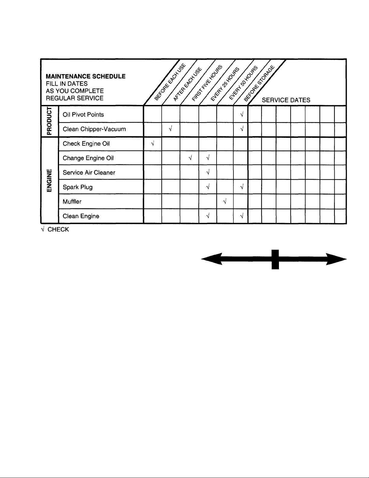
Schedule
8
9
Engine
Chipper-Vacuum
Oil
.........................
Operating Tips
Repair/Replacement Parts .
Responsibilities, Customer.
Safety Rules ..
Sharpening ....
Spark Plug
Specifications.
Storage
Table of Contents
Trouble Shooting.
Unclogging.
Unpacking..
Warranty ................................................................4
...................................................
.....................
M
..........
..............
.....
R
...
........
U
W
.................
.......
.....
.4, 13, 14
........
....
..........
..........
..........
8-11
12, 13
14-17
19-25
........
......
13
.13, 14
.13, 18
.13
.10
20-35
2, 3
15, 16
14
4
18
...5
.19
.15
...6
4
ACCESSORIES
These accessories were available when the chipper-vacuum was purchased. They are also available at most
Sears retail outlets, catalog and service centers. Most Sears stores can order repair parts for you, when you
provide the model number of your chipper-vacuum.
Spark
Plug
Air
Filter
ENGINE
Muffler Engine
Oil
Gas Can
Stabilizer
CHIPPER-VACUUM
Page 6
ASSEMEILY INSTRUCTIONS
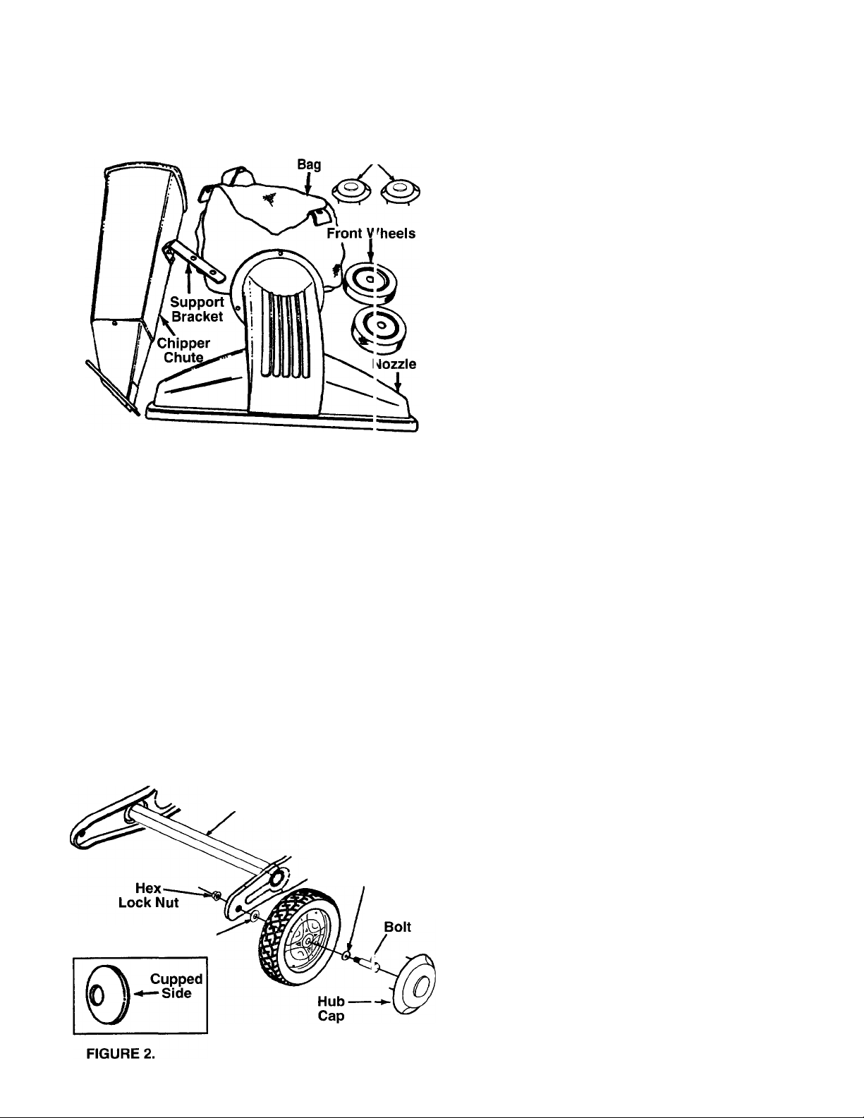
FIGURE 1.
Hub Caps
LOOSE PARTS IN CARTON
(2) Front Wheels
(2) Hub Caps
(1) Nozzle Assembly
(1) Chipper Chute
(1) Support Bracket
tNot Shown
IMPORTANT: This unit is shipped WITHOUT GASO
LINE or OIL in the engine. After assembly, see opera
tion section of this manual for proper fuel and engine
oil recommendations.
NOTE: To determine right and left hand sides of your
chipper-vacuum, stand behind and face the unit
(Refer to figure 7).
Your chipper-vacuum has been completely assem
bled at the factory except for the front wheels, hub
caps, nozzle, chipper chute, support bracket and bag.
A pair of safety glasses and bottle of oil are also
included in the carton.
(See Figure 1)
(1) Bag
(1) Shift Knob
(1) Tamper Plugt
(1) Safety Glassest
(1) Bottle of Oi If
REMOVING CHIPPER-VACUUM FROM CARTON
Cut the corners of the carton. Remove all packing
inserts and loose parts. Push down on handle to lift
front of chipper-vacuum, and roll chipper-vacuum out
of the carton. Make certain all parts and literature
have been removed before the carton is discarded.
Wheel Bracket
Cupped Washer.
Wave
Washer
Shoulder
TOOLS REQUIRED FOR ASSEMBLY
(1) 3/4" Open End Wrench
(2) 1/2" or Adjustable Wrenches
Ò) 9/16" Wrench
(1) Funnel
Ò) Set of Pliers
(1) 7/16" Wrench
SETTING-UP YOUR CHIPPER-VACUUM
ATTACHING THE FRONT WHEELS
• Tilt unit backward so that it rests on the handle
(place a piece of the carton under handle to avoid
scratches). Remove the cardboard packing
material around the wheel brackets.
• Remove the hex lock nuts and shoulder bolts from
the front of the wheel brackets. See figure 2.
• Place wave washer on shoulder bolt. Insert
shoulder bolt through wheel, with the head of the
shoulder bolt through the flat side of the wheel.
• Assemble wheel to outside of wheel bracket.
Secure with cupped washer and hex lock nut.
Tighten the nut. The cupped side of washer goes
on end of shoulder bolt between the wheel and the
bracket.
Page 7
• Align the four tabs on the hub caps with the four
holes in the wheel. Press in each tab until it locks in
place. The hub cap edges must be flush with the
wheel rim when installed properly.
• Push the hub cap onto the wheel so that the edges
of the hub cap flush with the rim of the wheel.
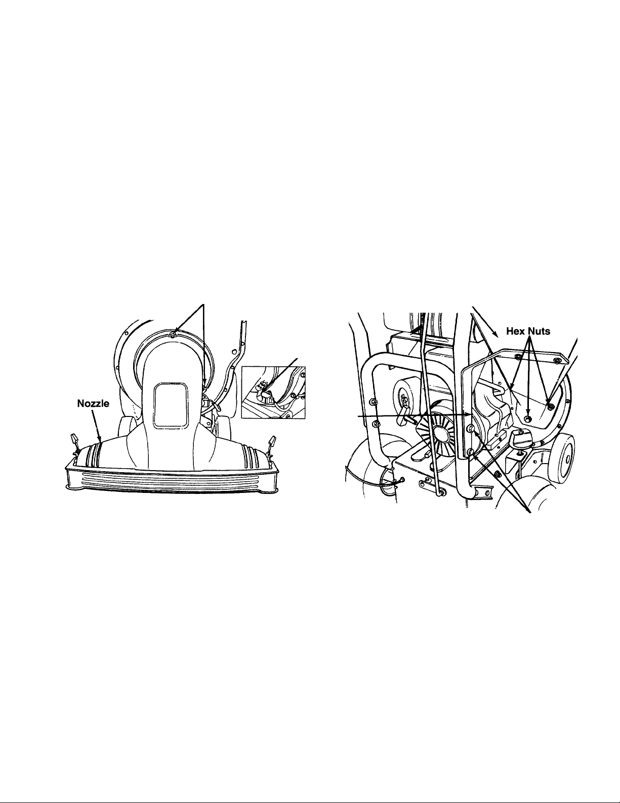
ATTACHING THE NOZZLE (See figure 3)
• Remove the three wing nuts from the front of the
chipper-vacuum. Place the nozzle in position over
the three weld studs. Secure with the wing nuts just
removed.
NOTE: The metal tab in the nozzle must depress the
safety switch on the front of the chipper-vacuum or
the engine will not start.
• Set unit in upright position.
• Remove the two hex bolts, flat washers, and nuts
which are attached to the support bracket. See
figure 4.
• Use this hardware to attach the support bracket to
the bottom of the chipper chute loosely. Be sure to
fix the hardware so that the heads of the hex bolts
and washers are inside the chipper chute.
• Place the support bracket over the two bolts in the
handle. Push up the chipper chute in order to better
align the holes in the support bracket with the bolts
in the handle. Put the nuts back on.
• Tighten all hardware securely first on the chipper
chute, then on the support bracket, and finally on
the handle.
Wing Nuts
Metal Tab
Support
Bracket
FIGURE 3.
ATTACHING THE CHIPPER CHUTE AND
SUPPORT BRACKET
• Remove the two hex lock nuts from the hex bolts
which secure the right side of the upper handle to
the lower handle. Leave the bolts in place. See
figure 4.
• Remove the three cupped washers and hex nuts
from the weld studs. You will find these weld studs
beside the opening on the right side of the chipper
vacuum. See figure 4.
• Place the chipper chute over the weld studs.
Secure with cupped washers and hex nuts that you
earlier removed. See figure 4. Do not tighten it all
the way.
NOTE: Cupped side of the washer goes against the
chipper chute. See figure 2 inset to find out the
cupped side of a washer.
Chipper
Chute
Hex Lock Nuts
FIGURE 4.—View from the operator’s position
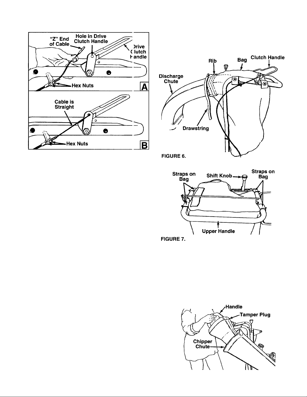
ATTACHING THE CLUTCH CABLE (See figure 5)
The clutch cable has been assembled at the factory.
You will have to attach the clutch cable to the drive
clutch handle.
• Loosen the hex nuts at the cable bracket and
remove.
• Holding the drive clutch handle up, hook the “Z”
end of the cable into the drive clutch handle from
the outside to the inside. See figure 5A. You will
need a pair of pliers for this.
• Next keeping the clutch handle up, tighten the back
hex nut approximately halfway with no slack in the
cable when it is attached and the “Z” end is in
place.
Page 8
• Squeeze the clamp on the drawstring and pull the
FIGURE 5.
ADJUSTING THE CLUTCH CABLE
• While adjusting the hex nuts at the cable t racket,
make sure that there is no slack in the cable, but
the cable is not tight. See figure 5B. Do not over
tighten the cable.
To check the clutch adjustment, proceed as fol ows.
• Push the chipper-vacuum backward and lorward
with the drive clutch handle released. It should
move freely. If it does not, loosen both hex nuts at
the cable bracket. See figure 5B. Turn botlom nut
counterclockwise to loosen the cable.
• Holding against the upper handle, engage tf e drive
clutch handle and try to push the unit backward
and forward. The wheels should lock up.
• If the wheels do not lock up, loosen both h jx nuts
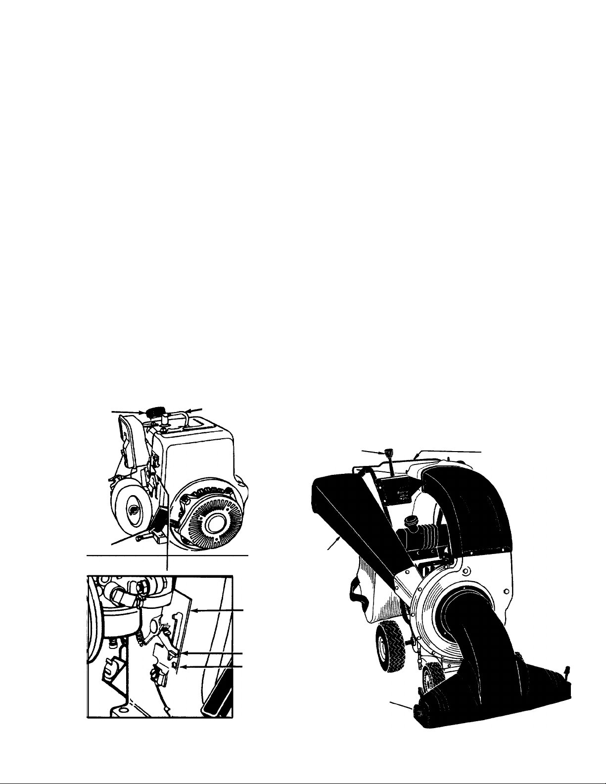
INSERTING THE TAMPER PLUG
The handle of the tamper plug must be vertical.
• Match the angle of the tamper plug with the angle
at the cable bracket. Turn front nut clock vise to
tighten the cable.
• Recheck the adjustment. Tighten both the h 3X nuts
when you have adjusted it correctly.
• Insert the tamper plug into the chipper chute.
NOTE: Tamper plug should remain in the chipper
chute whenever the chute is not in use.
INSTALLING THE SHIFT KNOB
• Thread the shift knob onto the end of tte shift
lever.
ATTACHING THE BAG
• Place bag inside the handle assembly. £ lip the
opening on the bag over the discharge chute. Make
sure that it is over the rib on the discharge chute.
See figure 6.
• Place the four straps on top of the bag o rer the
upper handle, hooking them on the studs. See fig
ure 7. Make sure that the bag goes under tfe drive
clutch handle.
FIGURE 8.
drawstring tight. Release the clamp.
Drive
of the chipper chute. See figure 8.
Page 9
OPERATION
OPERATING CONTROLS
SHIFT LEVER—The shift lever determines ground
speed of your unit. It may be placed in one of eight
positions. Of these eight, six positions are to go for
ward, and two positions are to go in reverse.
Forward: Six speeds according to the six positions of
the shift lever are available; position one is the slow
est, and position six is the fastest.
Reverse: Two speeds according to the two positions
of the shift lever are available; position R (extreme
right) is the faster of the two.
DRIVE CLUTCH HANDLE (BAIL)—If you squeeze
the drive clutch handle against the upper handle, you
will engage the wheel drive. If you release the drive
clutch handle, you will stop the wheel drive.
CHOKE LEVER—This chipper-shredder unit is
equipped with a choke lever which is used to start a
cold engine.
(See Figure 9)
STARTER HANDLE—This is used to start the engine
manually.
THROTTLE CONTROL—This controls the engine
speed and stops the engine. It is located right above
the starter handle.
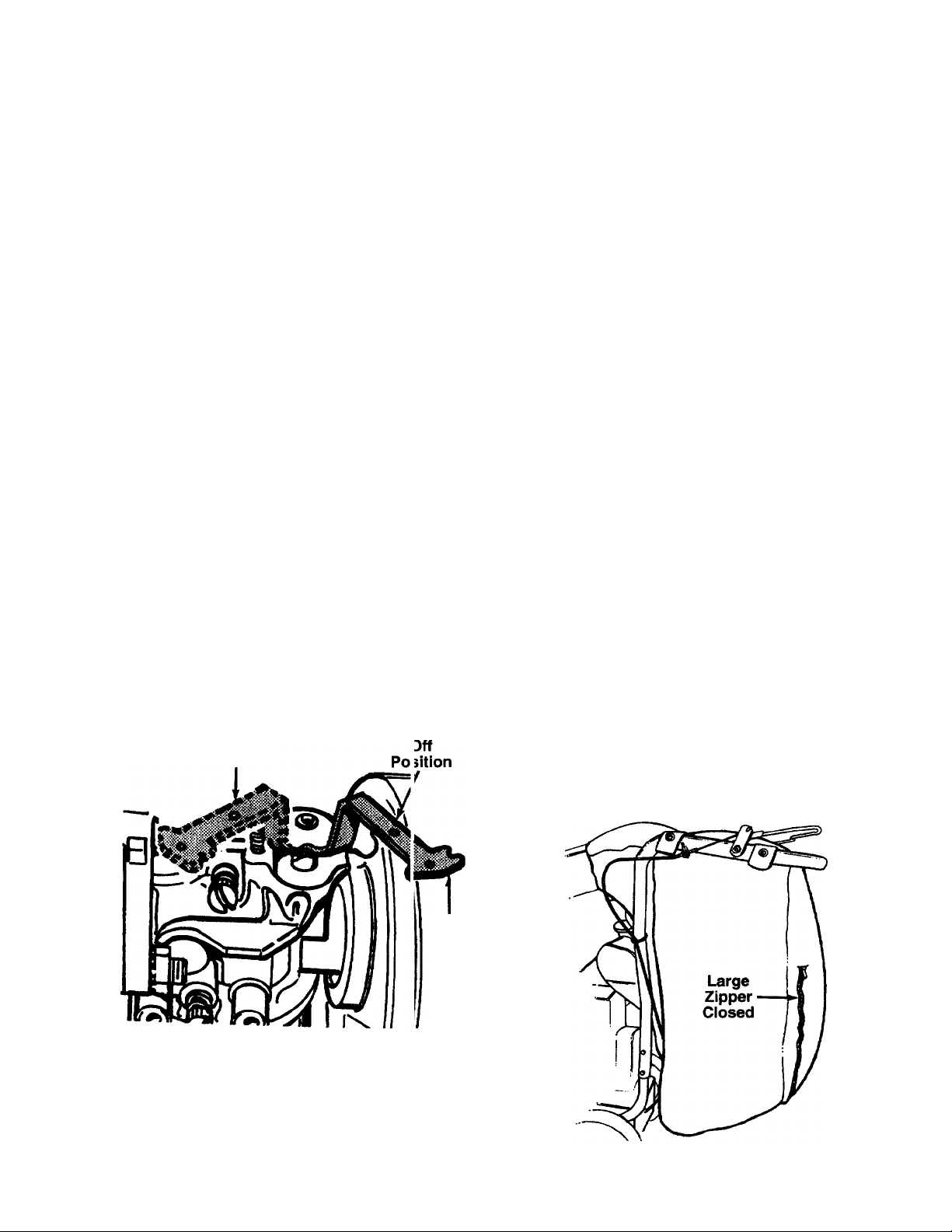
TO STOP THE ENGINE
• Move throttle control lever to STOP position. See
figure 9.
• Disconnect spark plug wire and move away from
the spark plug to prevent accidental starting while
the equipment is unattended.
Oil Fill-
Dipstick
Choke
Lever ■
Starter
Handle
Spark Plug
Wire and Boot
Fast
■Throttle
Stop
Shift
Lever
Chipper
Chute
Drive Clutch
Handle
FIGURE 9.
Nozzle
Page 10
BEFORE USING YOUR CHIPPER-VACUUM
THIS MANUAL ALWAYS BE CAREFUL
The operation of any chipp ir-vacuum can result in foreign objects being thrown into the eyes, which
can damage your eyes se^ erely.
shieids before chipping, nr while performing any adjustments or repairs.
Vision Safety Mask for over spectacles or standard glasses available at Sears Retail Stores.
REFER TO THE “SAFETY RULES” AS SHOWN ON PAGE 2 OF
Always wear the safety glasses provided with this unit or eye
USING THE CHIPPER-VACUUM
NOTE: Your chipper-vacuum unit has a safely switch
at the front of the housing. The nozzle or hose attach
ment must be in place on the chipper-vacuun before
the engine can be started.
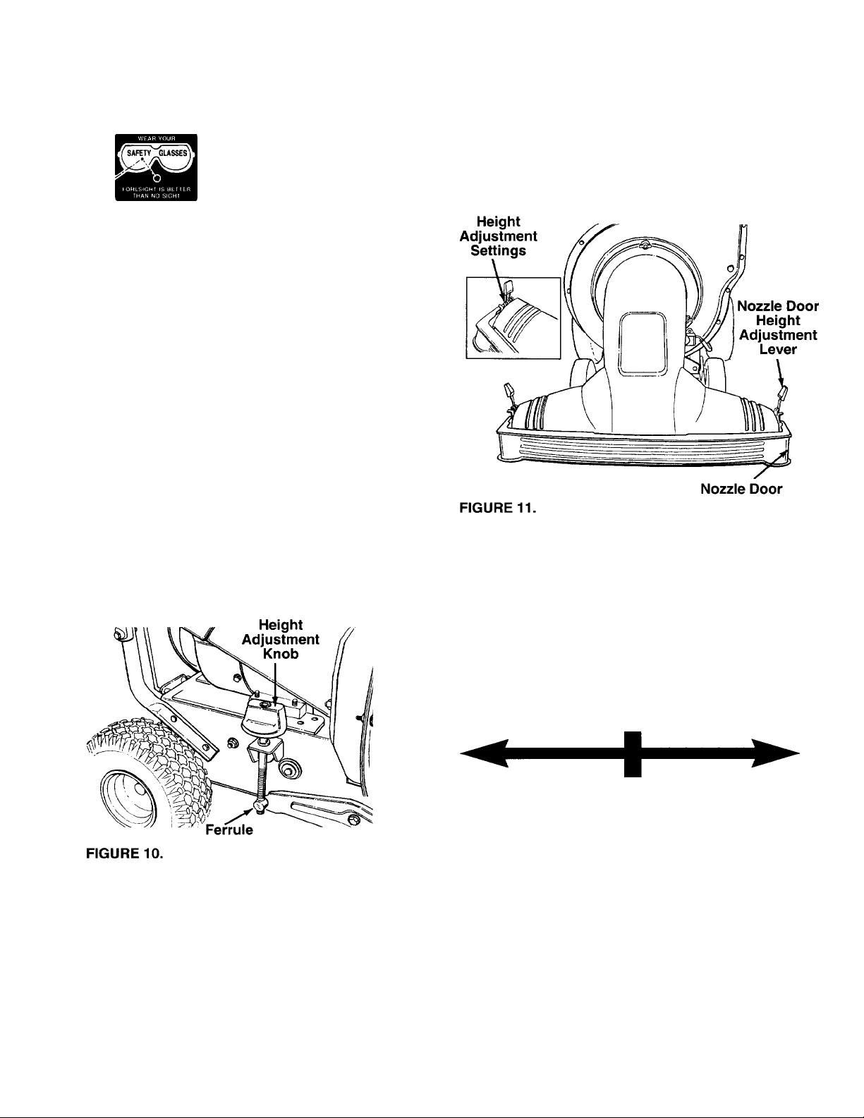
TO ADJUST THE NOZZLE HEIGHT
A. The height adjustment knob is located on the right
hand side of the chipper-vacuum. See figu e 10 for
its actual location. Adjusting the height here will
also raise or lower the height of the no2zle. For
further adjustment of the nozzle height t( i control
the flow, see the next section.
• Turn the knob clockwise to raise the wheels and
adjust the height of the unit.
• Turn the knob counterclockwise to lower th-j unit.
NOTE: Do not turn the knob too far to preven: the rod
from coming out of the ferrule.
We recommend Wide
NOTE: In general, raise the nozzle height to vacuum
a thick layer of leaves; lower the nozzle height for
smoother surfaces.
B. Your chipper-vacuum unit has a noz2le door
height adjustment lever with three set ings on
each side of the nozzle door. See figure ' 1 for its
actual location. The nozzle door height h is to be
adjusted according to the conditions.
• Slide the height adjustment lever forward Dr back
ward for adjusting the nozzle door upv ards or
downwards.
GAS AND OIL FILL-UP
OIL
Only use high quality detergent oil rated with API
service classification SF, SG or SH. Select the oil’s
viscosity grade according to your expected operating
temperature.
Colder
5W30
NOTE: Although multi-viscosity oils (5W30, 10W30,
etc.) improve starting in cold weather, these multi
viscosity oils will result in increased oil consumption
when used above 32°F. Check your oil level more
frequently to avoid possible engine damage from
running low on oil.
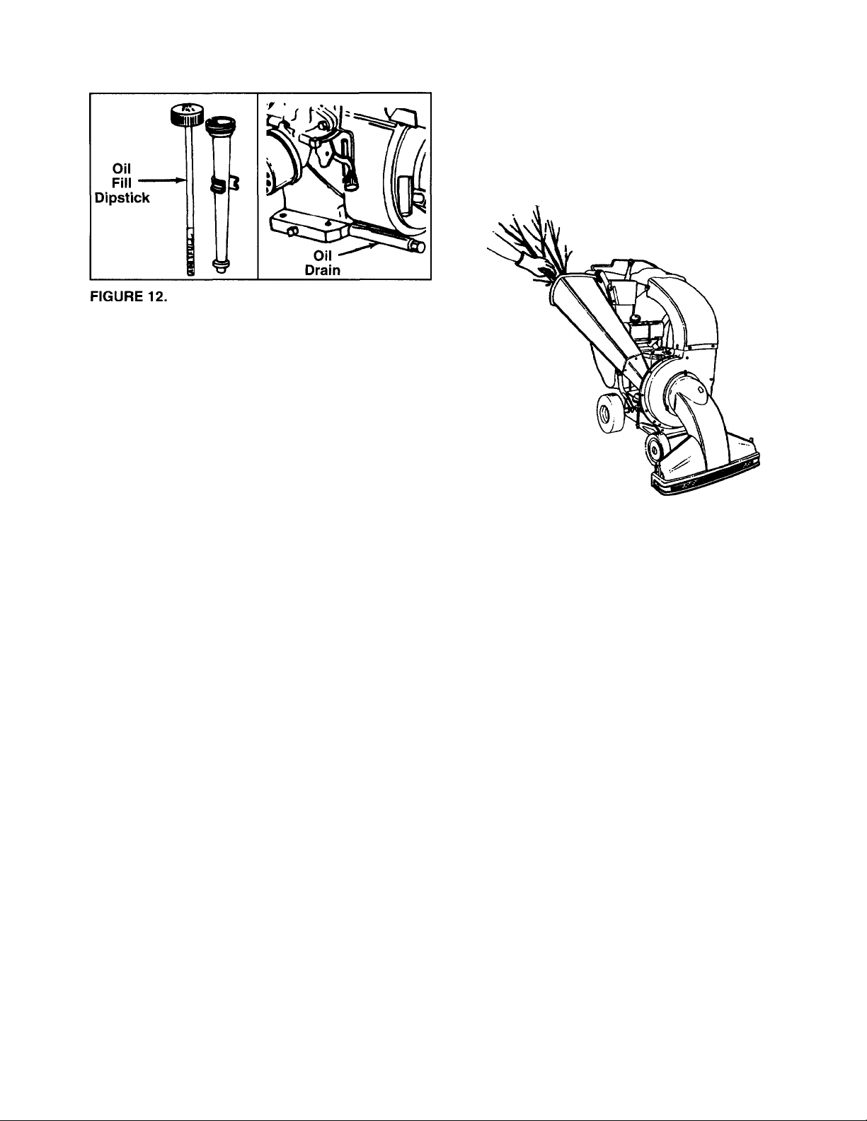
• Use engine oil provided. Remove oil fill dipstick.
See figure 12. With chipper-vacuum level, use a
funnel to fill engine with oil to FULL mark on dip
stick. Capacity is approximately 20 ounces. Be
careful not to overfill. Oil bottle provided contains
20 oz. of oil. Tilt chipper-vacuum toward the left
(from behind the hopper), then re-level. Check oil
level. Refill to FULL mark on dipstick if necessary.
Replace dipstick and tighten.
32“F Warmer
SAE 30
10
Page 11
GAS
Remove fuel cap and till fuel tank with approxi
mately 1 gallon of clean, fresh, lead-free grade
automotive gasoline. DO NOT use Ethyl or high
octane gasoline. Be certain container is clean and
free from rust or foreign particles. Never use gaso
line that may be stale from long periods of storage
in the container. Replace fuel cap.
WARNING: DO NOT FILL CLOSER THAN
1/2 INCH OF TOP OF FUEL TANK TO
A
Check the fuel level periodically to avoid running out
of gasoline while operating the chipper-vacuum. If the
unit runs out of gas as it is chipping, it may be neces
sary to unclog the unit before it can be restarted.
Refer to “Removing the Flail Screen” in SERVICE
AND ADJUSTMENT section.
PREVENT SPILLS AND TO ALLOW FOR
FUEL EXPANSION. IF GASOLINE IS
ACCIDENTLY SPILLED, MOVE CHIPPERVACUUM AWAY FROM AREA OF SPILL.
AVOID CREATING ANY SOURCE OF
IGNITION UNTIL GASOLINE VAPORS
HAVE DISAPPEARED.
USING THE CHIPPER CHUTE
NOTE: Do not try to chip any material other than veg
etation like branches, leaves, twigs, etc., in a normal
yard. Such materials of up to 3" diameter may be fed
into the chipper chute. See figure 13.
FIGURE 13.
WARNING: DO NOT FEED ANY MATERI
AL MORE THAN 3" DIAMETER
▲
VEGETATION INTO THE CHUTE. PER
SONAL INJURY AND/OR DAMAGE TO
THE UNIT COULD RESULT IF YOU TRY
TO FEED ANY MATERIAL OTHER THAN
SPECIFIED HERE.
If necessary, use the tamper plug to push the
material into the chipper chute. See figure 8 for the
location of the tamper plug.
Place tamper plug inside the chute when not in use
to deaden the noise.
WARNING: EXPERIENCE INDICATES THAT ALCO
HOL BLENDED FUELS (CALLED GASOHOL OR
USING ETHANOL OR METHANOL) CAN ATTRACT
MOISTURE WHICH LEADS TO SEPARATION AND
FORMATION OF ACIDS DURING STORAGE.
ACIDIC GAS CAN DAMAGE THE FUEL SYSTEM
OF AN ENGINE WHILE IN STORAGE. TO AVOID
ENGINE PROBLEMS, THE FUEL SYSTEM
SHOULD BE EMPTIED OR TREATED WITH FUEL
STABILIZER BEFORE STORAGE FOR 30 DAYS
OR LONGER. USE FRESH FUEL NEXT SEASON.
SEE “STORAGE” SECTION FOR ADDITIONAL
INFORMATION.
NEVER USE ENGINE OR CARBURETOR CLEAN
ER PRODUCTS IN THE FUEL TANK OR PERMA
NENT DAMAGE MAY OCCUR.
WARNING: NEVER PLACE
A
For best performance, keep the chipper blades
sharp.
If the discharged material starts to become stringy,
or if the rate of discharge slows down considerably,
the chipper blades may have become dull. To
sharpen or replace the blade, refer to Service and
Adjustment section.
If the flail screen, located inside the housing in the
discharge area, becomes clogged, remove the
screen and clean. For instructions on cleaning the
screen, refer to the Service and Adjustment sec
tion.
INSIDE THE CHIPPER CHUTE.
HANDS
11
Page 12
TO START THE ENGINE
IMPORTANT: IF YOUR UNIT SHOWS ANY 5IGN OF
MOTION WITH THE CLUTCH HANDLE DISEN
GAGED, SHUT THE ENGINE OFF IMMECIATELY.
READJUST FOLLOWING INSTRUCTIONS FOR
"FINAL ADJUSTMENT” IN THE ASSEMBLY
SECTION OF THIS OWNER’S GUIDE.
WARNING: MAKE SURE THAT NO ONE
OTHER THAN THE OPERATOR IS
A
• Attach spark plug wire and rubber boot to spark
plug if necessary. See figure 9 for location,
• Place the throttle control lever in FAST poi ition.
• Move choke lever to full choke position as in figure
• Place one foot on the left rear wheel to pr event the
• Grasp starter handle and pull rope out slowly until
engine reaches start of compression c^cle. The
STANDING NEAR THE CHIPPERVACUUM UNIT WHILE STARTING OR
OPERATING.
DO NOT OPERATE THIS UNIT UNLESS
THE NOZZLE, DISCHARGE CHUTE, AND
THE BAG HAVE BEEN PROPERLY
INSTALLED.
14.
unit from skidding while starting.
rope will pull slightly harder at this point, Let the
rope rewind slowly.
• Pull the rope with a rapid, continuous, full arm
stroke.
• Keep a firm grip on the starter handle. Let the rope
rewind slowly. Do not let the starter handle snap
back against the starter.
• Repeat until engine cranks up. When the engine
starts, move the choke lever halfway between
CHOKE and OFF.
• Move throttle control to IDLE position for a few min
utes to warm up the engine. Move it back when
running.
• Move the choke lever to OFF position as the
engine warms up.
NOTE: To idle smoothly, a new engine may require 3
to 5 minutes of running at above the slow idle speed.
The idle speed has been adjusted for proper running
after this break-in period.
TO STOP ENGINE
• Move throttle control lever to STOP position.
• Disconnect spark plug wire and move away from
spark plug to prevent accidental starting while
equipment is unattended.
TO EMPTY BAG
Open the large zipper on the bag to empty the bag.
See figure 15. Be certain the zipper is ciosed when
operating the unit.
Fuli Choke
Position
Choke
Lever
FiGURE 14.
NOTE: While the engine is reaching the con ipression
cycle, you may hear a noise. This noise is caused by
the flails and fingers falling into place and i s normal.
This noise will continue till impeller reaches full speed.
FIGURE 15.
12
Page 13
CUSTOMER RESPONSIBILITIES
GENERAL RECOMMENDATIONS
WARNING: ALWAYS STOP THE ENGINE
AND DISCONNECT THE SPARK PLUG
A
• Periodically check all fasteners and be sure they
are tight.
• Follow the Maintenance Schedule above.
WIRE BEFORE PERFORMING ANY
MAINTENANCE OR ADJUSTMENTS.
CHIPPER-VACUUM
LUBRICATION
Lubricate the pivot points on the height adjustment
mechanism once a season using a light oil.
CLEANING
• Clean the chipper-vacuum thoroughly after each
use.
• Wash the bag periodically with water. Allow to dry
thoroughly in the shade. Do not use heat.
ENGINE
ENGINE OIL
Only use high quality detergent oil rated with API
service classification SF, SG or SH. Select the oil’s
viscosity grade according to your expected operating
temperature.
Colder
5W30
NOTE: Although multi-viscosity oils (SE30, 10W30,
etc.) improve starting in cold weather, these multi
viscosity oils will result in increased oil consumption
when used above 32°F. Check your oil level more
frequently to avoid possible engine damage from
running low on oil.
Your four-cycle engine will normally consume some
oil—therefore, check engine oil level regularly approx
imately every five hours of operation and before each
usage. Stop engine and wait several minutes before
checking oil level. With engine cooled down, the oil
level must reach FULL mark on dipstick (refer to
figure 12). Change engine oil after the first five hours
of operation, and every twenty-five hours thereafter.
To Drain Oil:
• Drain oil while engine is warm.
a. Remove oil drain cap. Refer to figure 12. Catch
oil in a suitable container.
b. When engine is drained of all oil, replace drain
cap securely.
• Refill with fresh oil. Refer to GAS AND OIL FILL
UP section.
• Replace dipstick.
32°F
Warmer
SAE 30
13
Page 14
AIR CLEANER
The air cleaner prevents damaging dirt, du st, etc.,
from entering the carburetor, and being forced into the
engine. It is important to keep the engine clear to pro
long engine life and improve performance.
Never run your engine without air cleaner com
pletely assembled.
To Service Air Cleaner:
Service pre-cleaner after every 25 hours of us e, or at
least once a season. Replace filter every 100 hours of
use, or at least once a season. Service pre-clesner and
filter more often under dusty conditions.
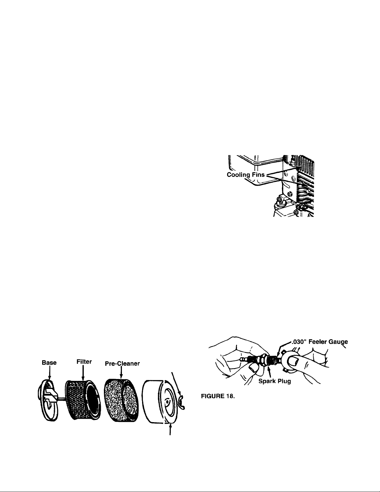
• Remove wing nut and cover. See figure 16.
• Slide pre-cleaner off filter. Clean the inside of base
and cover thoroughly.
• Clean pre-cleaner as follows.
Wash in water and detergent solution, and £ queeze
(do not twist) until all dirt is removed.
Rinse thoroughly in clear water.
Wrap in a clean cloth and squeeze (do not twist)
until completely dry, or allow to air dry.
• If necessary, replace filter (do not attempt tc clean).
• Install new filter on base. Slide pre-dearer over
filter.
• Install cover and wing nut. Tighten w ng nut
securely.
CLEAN ENGINE
Clean engine periodically. Remove dirt and debris
with a cloth or brush. Cleaning with a forceful spray of
water is not recommended as water could contami
nate the fuel system.
Yearly or every 25 hours of using, whichever occurs
first, remove the air intake screen and blower
housing, and clean the areas shown in figure 17 to
avoid overspeeding, overheating and engine damage.
Clean more often if necessary.
A
FIGURE 17.
SPARK PLUG
The spark plug should be cleaned and the gap reset
to .030" at least once a season or after every 50
hours of operation. See figure 18. Spark plug replace
ment is recommended at the start of each season.
Replace spark plug if electrodes are pitted, burned,
fouled with deposits, or porcelain is cracked. Refer to
engine parts list for correct spark plug type.
NOTE: Do not sandblast spark plug. Spark plug
should be cleaned by scraping or wire brushing and
washing with a commercial solvent.
WARNING: PERIODICALLY CLEAN MUF
FLER AREA TO REMOVE ALL GRASS,
DIRT AND COMBUSTIBLE DEBRIS.
FIGURE 16.
Л/ing
Nut
( ¡over
MUFFLER
Do not operate the chipper-vacuum without a muffler
or tamper with the exhaust system. Damaged mufflers
or spark arresters could create a fire hazard. Inspect
periodically, and replace if necessary. If your engine
is equipped with a spark arrester screen assembly,
remove after every 50 hours of using for cleaning and
inspection. Replace if damaged.
14
Page 15
SERVICE & ADJUSTMENT
WARNING: ALWAYS STOP ENGINE AND
DISCONNECT SPARK PLUG WIRE AND
A
REMOVING THE FLAIL SCREEN
If the discharge area becomes clogged, remove the
flail screen and clean area as follows.
• Stop the engine. Make certain the chipper-vacuum
has come to a complete stop. Disconnect the spark
plug wire before unclogging the discharge chute.
• Remove the vacuum bag from the unit.
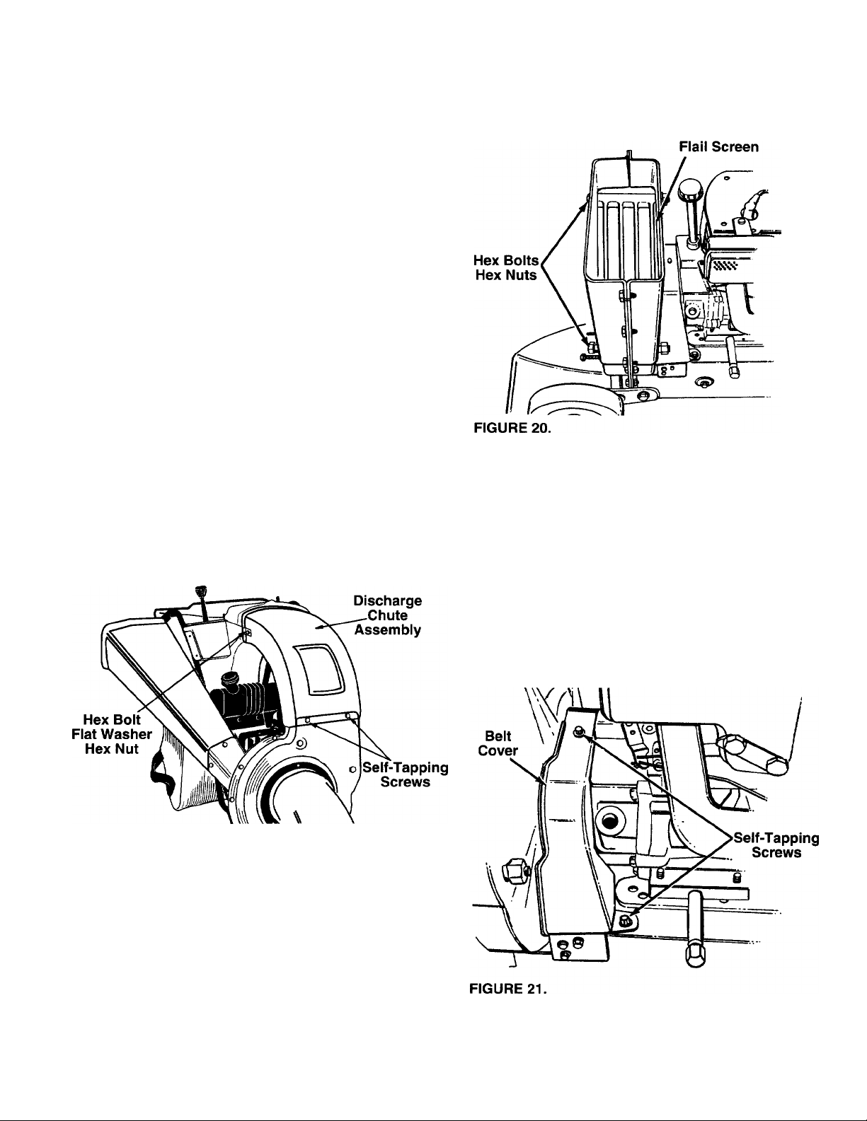
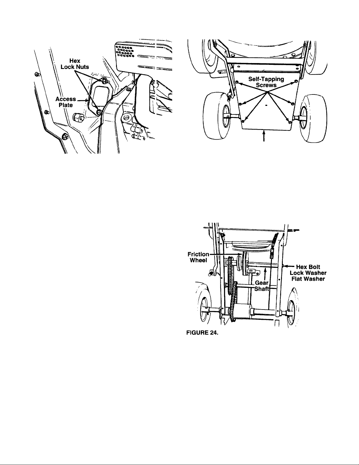
• Remove the four self-tapping screws from the
bottom of the discharge chute. (Be careful not to
drop the hardware into the chute.) Remove the dis
charge chute assembly. See figure 19.
MOVE IT AWAY FROM SPARK PLUG
BEFORE PERFORMING ANY ADJUST
MENTS OR REPAIRS.
• Clean the screen by scraping or washing with
water. Reinstall the screen.
NOTE: Be certain to reassemble the flail screen with
the curved side down as shown in figure 20.
SHARPENING OR REPLACING CHIPPER BLADES
• Disconnect the spark plug wire and move away
from the spark plug.
• Remove the flail screen as instructed in the previ
ous section.
• Remove the belt cover on the front of the engine by
removing the two self-tapping screws. See figure 21.
FIGURE 19.
• Remove the two hex bolts and hex nuts which
extend through the housing. Lift the flail screen
from inside the housing. See figure 20.
Remove the access plate by removing two hex lock
nuts. See figure 22.
15
Page 16
Frame Cover
FIGURE 22.
WARNING: MAKE SURE TO V/EAR
HEAVY DUTY GLOVES FOR THIS JOB.
A
• Locate one of the chipper blades in the c ccess
plate opening by rotating the impeller asserr bly by
hand. Remove the blade using a 3/16" aiien
wrench on the outside of the blade and 1/2" \/rench
on the impeller assembly, inside the hojsing.
Torque hardware to 250-350 inch pounds.
• Remove the other blade in the same m;inner.
Replace or sharpen blades. If sharpening, make
certain to remove an equal amount frorr each
blade. Reassemble in reverse order.
NOTE: Make sure that the blades are reasse mbied
with the sharp edge facing upward, as viewe i from
the access plate opening.
WHILE ACCESSING THE CHIPPER
BLADE, YOU MAY HAVE TO CLEA vl THE
SCREW HEAD OF DUST AND
SHREDDED PARTICLES TO ENABLE
THE ALLEN WRENCH TO OPERATE.
HANDLE THE WRENCH CAREFULLY SO
THAT YOU DO NOT CUT YOUR HAND
ON THE CHIPPER BLADE.
FIGURE 23.
Remove the gear shaft from the unit by removing
the hex bolts, lock washers and flat washers from
each side of the frame. See figure 24. Hold the fric
tion wheel assembly, and slide the gear shaft out of
the unit toward the right side.
CHANGING THE FRICTION WHEEL RUBBER
The rubber on the friction wheel is subject to wear
and should be checked after 50 hours of operation,
and periodically thereafter. Replace friction wheel
rubber if any signs of wear or cracking are found.
• Drain the gasoline and oil from the ch ppervacuum.
• Tip the unit backward so it rests on the handl 3S.
• Remove the frame cover by removing eight self
tapping screws from underneath the chippervacuum. See figure 23. (Only six of the eight
screws are shown in the figure.)
16
• Remove the six screws from the friction wheel
assembly (three from each side). Remove the fric
tion wheel rubber from between the friction wheel
plate.
• Reassemble new friction wheel rubber to the fric
tion wheel assembly, tightening the six screws in
rotation and with equal force.
• Slide the friction wheel assembly up onto the shift
mechanism, then slide the gear shaft back into the
unit. Reassemble in reverse order.
• Readjust the clutch cable. Refer to adjustment sec
tion.
Page 17

ADJUSTING THE CLUTCH CABLE
To adjust the clutch cable, refer to the “Clutch Cable
Adjustment” section of Assembly Instructions.
ADJUSTING THE SHIFT ROD
If the shift rod is at 1 or R1 position, but the unit does
not show any forward or reverse movement as the
case may be, the shift rod wiil need to be adjusted.
See figure 25.
• Remove the bag from the unit.
• Remove the hairpin ciip and the fiat washer from
the upper end of the shift rod.
• Pull the ferrule out of the hole in the shift lever.
Make sure that you do not displace the wave wash
er from the ferrule.
• Place the shift iever in the 6th position which is aii
the way to the left.
REPLACING THE BELT
WARNING: Disconnect the spark plug
A
• Remove the plastic beit cover on the front of the
engine by removing two self-tapping screws. Refer
to figure 21.
• Drain the gasoiine and oii from the chipper-
vacuum.
• Tip the unit backward so that it rests on the
• Remove the frame cover by removing eight self
tapping screws from underneath the chippervacuum.
• Remove the idier puiley bracket as foiiows. See
figure 26.
• Take the tension off the belt by pivoting the idler
• Remove three self-tapping screws, and lift off the
wire and move away from the spark plug.
handies.
pulley toward you, and line up the holes in the idler
bracket assembly. Insert a nail or similar object
through the holes to hold the idler pulley in this
position.
idler bracket assembly.
• Push down on the shift rod.
• Thread the ferrule up or down the shift rod two
turns so that the ferrule lines up with the upper hoie
in the shift lever.
• Secure the ferrule to the shift lever using the fiat
washer and the hairpin clip.
Engine Pulley
Idler
Idler
Bracket
'Assembl
Self-Tapping
FIGURE 26.
• Remove the hex bolt and lock washer from the
• Loosen the nut on the stop bolt until there is clear
• Slip the belt between the friction wheel and friction
NOTE: The support bracket must rest on the stop bolt
after the new belt has been assembled.
m \
Screws
engine pulley. See figure 26. Slip the engine pulley
off the engine shaft, and remove the belt from the
pulley.
ance between the support bracket and the friction
wheel disc. See figure 27.
wheel disc. Remove and replace belt. Reassemble
following instruction in reverse order.
Pulley
a
17
Page 18

Support
ADJUSTING THE CARBURETOR
A
The carburetor has been pre-set at the factory and
should not require adjustment. However, if your
engine does not operate properly due to suspected
carburetor problems, take your chipper-vacuum to
your nearest SEARS Service Center.
SETTING ENGINE SPEED
Your engine speed has been factory set. Do not
attempt to increase engine speed or it may result in
personal injury. If you believe the engine is running
too fast or too slow, take your chipper-vacuum to the
nearest SEARS Service Center for repair and adjust
ment.
STORAGE
WARNING: IF ANY ADJUSTMENTS ARE
MADE TO THE ENGINE WHILE THE
ENGINE IS RUNNING (E.G. CARBURE
TOR), KEEP CLEAR OF ALL MOVING
PARTS. BE CAREFUL OF HEATED SUR
FACES AND MUFFLER.
Prepare your chipper-vacuum for storage at he end
of the season or if the unit will not be used for 30 days
or more.
WARNING: NEVER STORE MACHINE
WITH FUEL IN THE FUEL TANK INSIDE
A
NOTE: A yearly check-up by your local Sears Service
Center is a good way to make certain your ohippervacuum will provide maximum performance for the
next season.
OF BUILDING WHERE FUMEii MAY
REACH AN OPEN FLAME OR SPA RK, OR
WHERE IGNITION SOURCES ARE
PRESENT SUCH AS HOT WATER AND
SPACE HEATERS, FURNACES, CLOTHES
DRYERS, STOVES, ELECTRIC MOTORS,
ETC.
• Run the engine till the fuel tank is empty.
• Start the engine and let it run until the fuel lines and
• Never use engine or carburetor cleaner products in
• Use fresh fuel next season.
NOTE: Fuel stabilizer is an acceptable alternative in
minimizing the formation of fuel gum deposits during
storage. Add stabilizer to gasoline in fuel tank or stor
age container. Always follow the mix ratio found on
stabilizer container. Run engine at least 10 minutes
after adding stabilizer to allow the stabilizer to reach
the carburetor. Do not drain the gas tank and carbure
tor if using fuel stabilizer.
• Drain all the oil from the crankcase (this should be
CHIPPER-VACUUM
• Clean the chipper-vacuum thoroughly.
• Wipe unit with an oiled rag to prevent rus (use a
light oil or silicone).
• If you have drained the fuel tank, protect the inside
ENGINE
IMPORTANT: IT IS IMPORTANT TO PREVENT
GUM DEPOSITS FROM FORMING IN ESSENTIAL
FUEL SYSTEM PARTS SUCH AS CARBUFIETOR,
FUEL FILTER, FUEL HOSE, OR TANK DURING
STORAGE. ALSO, EXPERIENCE INDICATES THAT
ALCOHOL BLENDED FUELS (CALLED GA30H0L
OR USING ETHANOL OR METHANOL) CAN
ATTRACT MOISTURE WHICH LEADS TO SEPARA
TION AND FORMATION OF ACIDS DJRING
STORAGE. ACIDIC GAS CAN DAMAGE TH E FUEL
SYSTEM OF AN ENGINE WHILE IN STORACiE.
OTHER
• Do not store gasoline from one season to another.
• Replace your gasoline can if your can starts to rust.
• Store unit in a clean, dry area. Do not store next to
NOTE: If storing in an unventilated or metal storage
shed, be certain to rustproof the equipment by coating
with a light oil or silicone.
carburetor are empty.
the fuel tank or permanent damage may occur.
done after the engine has been operated and is still
warm) and refill the crankcase with fresh oil.
of the engine as follows. Remove spark plug, pour
approximately 1/2 ounce (approximately one table
spoon) of engine oil into cylinder and crank slowly
to distribute oil. Replace spark plug.
Rust and^r dirt in your gasoline will cause problems.
corrosive materials, such as fertilizer.
18
Page 19

TROUBLE SHOOTING
PROBLEM POSSIBLE CAUSE(S)
Engine fails to start
Loss of power;
operation erratic • Unit running on CHOKE.
Engine overheats • Carburetor not adjusted
Too much vibration
Unit does not
discharge
Rate of discharge
slows considerably or
composition of
discharged material
changes
• Fuel tank empty, or stale fuel. • Fill tank with clean, fresh fuel.
• Spark plug wire disconnected. • Connect wire to spark plug.
• Faulty spark plug.
• Nozzle safety switch not depressed.
• Spark plug wire loose.
• Blocked fuel line or stale fuel.
• Water or dirt in fuel system.
• Carburetor out of adjustment.
• Dirty air cleaner.
properly.
• Engine oil level low.
• Loose parts or damaged
impeller.
• Discharge chute clogged.
• Foreign object lodged in impeller.
• Vacuum bag is full.
• Chipper blades dull.
CORRECTIVE ACTION
• Clean, adjust gap or replace.
• Adjust metal tab so it depresses the safety switch.
• Connect and tighten spark plug wire.
• Move choke lever to OFF position.
• Clean fuel line; fill tank with clean
fresh gasoline.
• Disconnect fuel line at carburetor to drain fuel
tank. Refill with fresh fuel.
• Adjust carburetor or contact your SEARS
Service Center.
• Service air cleaner. See Customer Responsibilities
section of this manual.
• Contact your SEARS Service Center.
• Fill crankcase with proper oil.
• Stop engine immediately and disconnect
spark plug wire. Tighten all bolts and nuts.
Make all necessary repairs. If vibration continues,
have unit serviced by a SEARS Service Center.
• Stop engine immediately and disconnect
spark plug wire. Clean flail screen and inside
of blower housing. See Service/Adjustments
section of this manual.
• Stop engine immediately and disconnect
spark plug wire. Remove lodged object.
• Empty bag.
• Sharpen or replace chipper blades.
NOTE: For repairs beyond the minor adjustments listed above, please contact your nearest SEARS Service Center.
19
Page 20
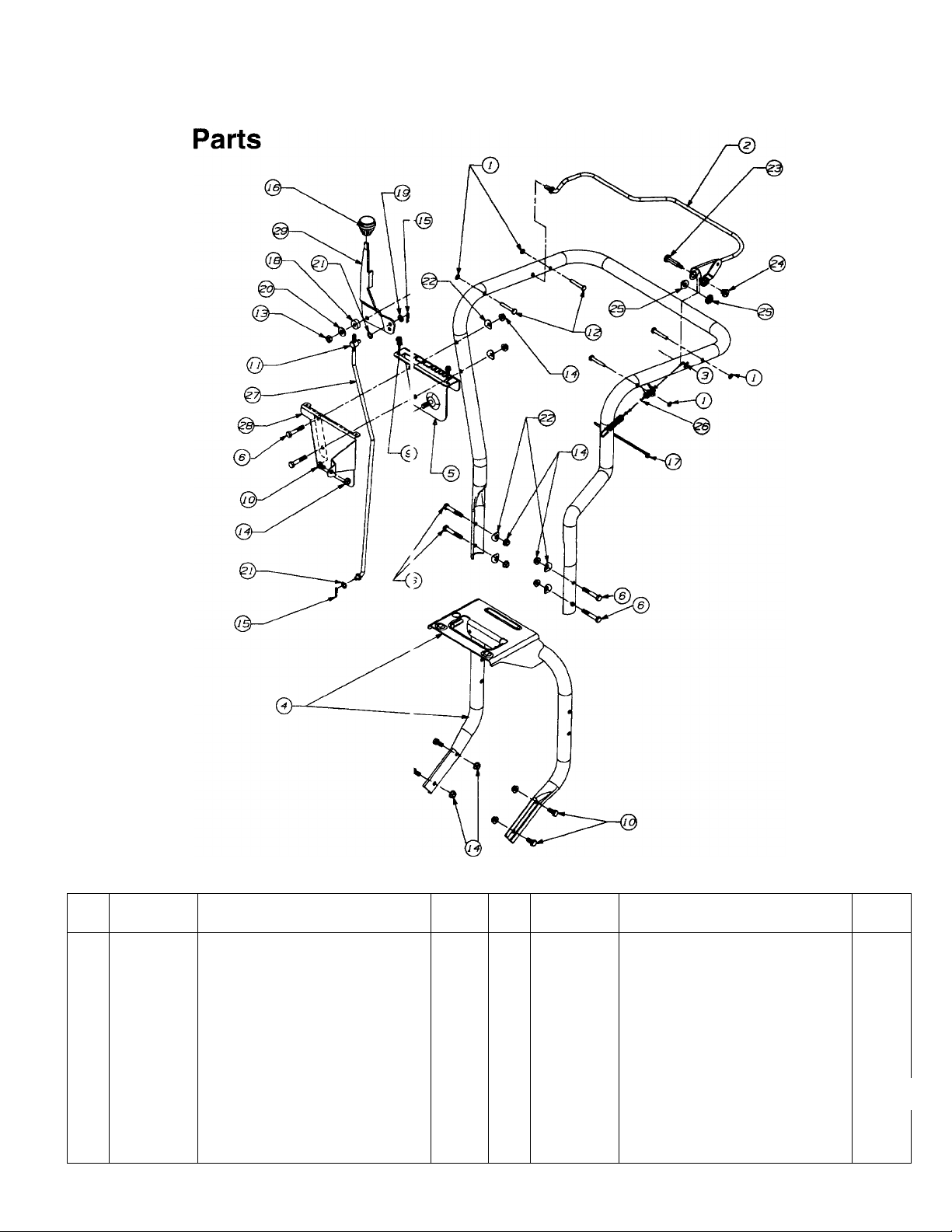
SEARS CRAFTSMAN CHIPPER-VACUUM MODEL 247.799620
REF.
NO.
10 710-3008
PART
NO.
1 1539-019
2 647-0019
3 649-0008
4 649-0012
5 681-0076
6 710-0116
710-0896
9
DESCRIPTION
PUSHNUT
CONTROL ASSY
HANDLE ASSY-UPPER
HANDLE-LOWER
BRACKET ASSY-SHIFT
SCREW-HEX
SCREW-HEX
SCREW-HEX 5
11 711-0677 FERRULE
711-0737 PIN-STUD
12
13
712-0116
NUT-HEX LOCK
14 712-3004A NUT-HEX LOCK
714-0104 PIN-COTTER
15
16 720-0232
KNOB-SHIFT
QTY.
4
REF.
NO.
17 725-0157 CABLE TIE
PART
NO.
1 18 735-0126
1
1
19
20
736-0264
736-0300
1 21 736-0413
6
22 736-0451
2 23 738-0560
24
1
4 26
1
25
27
738-0561
741-0402
746-0921
747-0626
11 28 781-0626
2 29
784-0297A
1
20
DESCRIPTION QTY.
1
WASHER-RUBBER
WASHER-FLAT
WASHER-FLAT
WASHER-SPRING
WASHER-SADDLE
SCREW-SHOULDER
NUT-SHOULDER
BEARING-FLANGE PLASTIC
CABLE-CLUTCH
ROD-SHIFT
COVER-SHIFT
HANDLE-SHIFT
1
1
1
2
6
1
1
2
1
1
1
1
Page 21

SEARS CRAFTSMAN CHIPPER-VACUUM MODEL 247.799620
Repair Parts
REF.
NO.
PART
NO.
DESCRIPTION
QTY.
REF.
NO.
PART
NO.
DESCRIPTION
1 629-0241 HARNESS—CHIPPER-VAC 1 13 712-3010 NUT-HEX (GR 5)
2 681-0059
3 681-0060
4 710-0382
710-0604 SCREW-HEX SELF TAP
5
710-0607
6
7 710-0772
8 710-1268
9 710-3008
712-0384
10
11 712-0421
HOUSING ASSY—INNER 1 14
HOUSING ASSY—OUTER 1 15
SCREW-HEX 2
SCREW-HEX SELF TAP
SCREW-HEX
SCREW-HEX SELF TAP 2 20
SCREW-HEX 2 21 736-0242 WASHER-BELL
NUT-HEX LOCK 2
KNOB
12 712-3004A NUT-HEX LOCK
719-0326
723-0438
16 725-1700 COVER-SWITCH 1
10
8 18
17
725-3166
726-0272 CLAMP
3 19 731-1613 COVER-SWITCH 1
736-0119
22 781-0598 BLADE-FLAIL HOUSING
3 23 781-0599 BLADE-FLAIL HOUSING
4 24
781-0627
SCREEN
SEAL-RUBBER
SNAP MOUNT SWITCH
WASHER-LOCK
COVER-CHIPPER 1
21
QTY.
3
1
2
1
1
3
3
1
1
Page 22

SEARS CRAFTSMAN CHIPPER-VAI^UUM MODEL 247.799620
Repair Parts
REF.
NO.
1
PART
NO.
DESCRIPTION
681-0051 IMPELLER ASSY COMP
(INCL. REF. NOS. 2 THRU 12)
2
3
710-1273
736-0217
SCREW-HEX 1
WASHER-LOCK
4 736-0247 WASHER-FLAT 1
681-0052 IMPELLER ASSY 1
5
711-0833B PIN-CLEVIS
6
7
710-1054
712-0411 NUT-HEX LOCK 4
8
715-0162 PIN-ROLL SPRING 3
9
SCREW-FLAT HEAD 4
10 719-0329 BLADE-FLAIL 3
11 736-0119 WASHER-LOCK
12
781-0490
BLADE-CHIPPER 4
QTY.
1
1
3
4
REF.
NO.
PART
NO.
1 710-0642
2 631-0043
3 731-1608
DESCRIPTION QTY.
HEX WASHER SCREW
NOZZLE ASSEMBLY
CHUTE 1
4 735-0247 NOZZLE FLAP
764-0484 VACUUM BAG 1
5
6 781-0666
7 631-0033
8 712-0431
720-0190 HEIGHT ADJ. KNOB
9
732-0754 SPRING LEVER 2
10
11 736-3084
781-0637 NOZZLE DOOR BRKT. 2
12
738-0913
13
NOZZLE STABILIZER BRKT. 1
NOZZLE DOOR ASSY 1
FLANG. LOCK NUT 2
FL-WASHER 2
SHOULDER SCREW 2
14 736-0173 FLAT WASHER 5
5
1
1
2
REF.
NO.
1
PART
NO.
681-0068
2
710-0258
712-3027 NUT-LOCK
3
DESCRIPTION
CHUTE ASSEMBLY 1
SCREW-HEX
4 731-1574 CHUTE-UPPER
5 781-0625
—
731-1617 TAMPER PLUG (Not Shown)
6 736-0173
BRACKET SUPPORT
WASHER
QTY.
5
5
1
1
1
5
22
Page 23

SEARS CRAFTSMAN CHIPPER-VACUUM MODEL 247.799620
Repair Parts
REF.
NO.
10 736-0329
11
12 754-0256 V-BELT
13 756-0313
14
15
16 781-0611 BRACKET-IDLER PIVOT
17
PART
NO.
1 710-0230 SCREW-HEX 1
2 710-0723
3 710-0896 SCREW-HEX
4 710-0646 SCREW-HEX
5 712-0266 NUT-HEX LOCK 1
712-3004A NUT-HEX LOCK FL
6
719-0330A
7
731-1584 COVER-BELT
8
9 732-0745 SPRING-TORSION 1
748-0234
756-0985 PULLEY
756-0984 PULLEY
781-0614
DESCRIPTION QTY.
SCREW-HEX 1
5
1
2
ADAPTER-MOUNTING 1
1
WASHER-LOCK
SHOULDER SPACER
1
1
1
IDLER-FLAT
1
1
1
1
BRACKET-IDLER 1
REF.
NO.
1
2
PART
NO.
681-0096
738-0955
DESCRIPTION QTY.
BRKT. ASSY.-WHEEL PIVOT
SCREW-SHOULDER
3 710-0924 SCREW-MACHINE PAN HD.
4
710-3008
SCREW-HEX 2
5 711-1041 FERRULE-ADJUSTABLE
712-3004A NUT-HEX FLANGE 2
6
7
712-0431
NUT-HEX FLANGE LOCK
8 714-0115 PIN-COTTER
9 716-0104 E-RING
10 720-0236 PLASTIC KNOB
11
736-0270
12
736-0300 FLAT WASHER
13
736-0369 FLAT WASHER
14
732-0645 COMPRESSION SPRING
BELL WASHER
15 747-0631 ADJUSTABLE ROD
16
711-0242
17
781-0605
736-0247 FLAT WASHER 2
18
SPACER
BRKT.-HEIGHT ADJ.
1
2
1
1
2
1
1
1
1
2
2
1
1
1
1
23
Page 24

SEARS CRAFTSMAN CHIPPER-VACUUM MODEL 247.799620
Repair Parts
24
Page 25

SEARS CRAFTSMAN CHIPPER-VACUUM MODEL 247.799620
Repair Parts
REF.
NO.
10
11
12
13
PART
NO.
684-0042A
1
2 618-0168
656-0012A
3
4 681-0055
681-0058
5
681-0082
6
681-0072 ARM ASSY-SHIFT 1 29 736-0160 WASHER-FLAT
7
681-0081
8
9 781-0638A
DESCRIPTION QTY.
FRICTION WHEEL ASSY 1 23 714-0474 COTTER PIN 1
DIFFERENTIAL ASSY COMP. 1
FR. WHEEL DISC ASSY 1 25 713-0284 CHAIN
SUPPORT BRKT. ASSY 1 26 732-0209 EXTENSION SPRING
AXLE BRKT. ASSY 2
SHAFT ASSY-SHIFT 1 28
FRAME ASSY 1 30 736-0267 WASHER-FLAT
FRAME PLATE
710-0502A SCREW-HEX SELF-TAP.
710-0653 SCREW-HEX WASHER 2 33 738-0908 IDLER BOLT
710-0788 SCREW-HEX WASHER
710-0896
SCREW-HEX 8 35 748-0382 SPACER
14 710-3008 SCREW-HEX 6
711-1073
15
711-1028 SHAFT-JACK
16
712-0241 NUT-HEX 2 39 750-0980 SPACER
17
712-0711 NUT-HEX JAM 1 40 750-0981 SPACER
18
712-3004A
19
713-0330
20
713-0374 CHAIN 1 43 750-0998 SPACER
21
22 713-0413
SHAFT-HEX
NUT-HEX FLANGE LOCK
SPROCKET & HUB 1 42
SPROCKET10T 1
REF.
NO.
24 716-0102
27
1
31
4 32
1 34
36
1
1
5
37
38 750-0979 SPACER
41 781-0612A
PART
NO.
DESCRIPTION QTY.
SNAP RING 1
736-0105 WASHER-BELL
736-0119
WASHER-LOCK
736-0287 WASHER-FLAT
736-3089
WASHER-FLAT
741-0563 BALL BEARING
750-0351 SLEEVE
750-0978 SPACER
FRAME COVER
784-5590
SHIFT BRACKET
1
2
3
2
1
2
4
2
1
2
1
1
1
1
1
1
1
1
1
REF.
NO.
PART
NO.
DESCRIPTION QTY.
1 634-0118 WHEEL ASSY COMPLETE
4" X 10" 2
634-0101 RIM ASSY COMPLETE 2
734-0210 TIRE PNEUMATIC 4" X 10" 2
711-1017 PIN-CLEVIS
2
712-0431 NUT-HEX FLANGE 2
3
714-0104
4
5 731-0355A
734-1268 WHEEL 2" X 8" 2
6
PIN-COTTER 2
HUB CAP 2
7 736-0105 WASHER-BELL 2
8
736-0232
WASHER-WAVE 2
9 738-0213 SCREW-SHOULDER 2
734-0255 VALVE STEM 2
10
2
25
Page 26

SEARS CRAFTSMAN CHIPPER-VAC JUM MODEL 247.799620
Repair Parts
REF.
NO.
PART
NO.
1
618-0168 DIFFERENTIAL ASSY
DESCRIPTION
COMPLETE 1
2
710-1206 SCREW-HEX 4
3 711-1035
4
711-1037 AXLE-SHAFT 10.95" LONG 1
5
711-1038
SHAFT-CROSS
AXLE-SHAFT 9.82" LONG
6 713-0445 SPROCKET 22 T 1
7 716-0232
RING-RETAINING
(2 PER AXLE)
8 717-1358
GEAR-DIFFERENTIAL 14T
9 717-1437 GEAR-DIFFERENTIAL 10T
10
719-0333
11
719-0334 HOUSING-DIFFERENTIAL LF 1
12
748-0383 BEARING-FLANGE 2
13
737-0300
14
— SEALANT-LOCTITE 5699
HOUSING-DIFFERENTIAL RM
GREASE
QTY.
1
1
4
2
2
1
1 OZ
REF.
NO.
1
PART
NO.
710-0258
DESCRIPTION QTY.
SCREW-HEX 2
2 712-3027 NUT-HEX LOCK FLANGE 2
3
4
5
6
7
726-0205
751-0535
751-0603
751-0610
726-0209
CLAMP-HOSE 2
HOSE-FUEL LINE 9" 1
CAP-FUEL 1
TANK-FUEL 1 GALLON 1
CABLE TIE 1
8 736-0173 FLAT WASHER 1
26
Page 27

SEARS CRAFTSMAN 9 H.P. ENGINE MODEL NO. 143.959003
FOR CHIPPER-VACUUM MODEL NO. 247.799620
Repair Parts
400
Page 28

SEARS CRAFTSMAN 9 H.P. ENGINE MODEL NO. 143.959003
FOR CHIPPER-VACUUM MODEL NO. >47.799620
Repair Parts
KEY
NO.
1
2
4 32678
5
15 30699C
15A 30700
15B 650494
16
17
18
19 34663
20
25 36460
26
28
30 36283
35
36
37
38
40
40
40
41 34329A Piston & Pin Ass’y. (Std.) (1 icl. 43)
41 34330A
41 34331A
42 34332
42 34333
42
43
45
46
47
48
49
50
60
65
69
70
71 35377
72
75
80 31845
81 30590A
82
83
84 29193
86
87
89
90
92
93
100
101
PART
NO.
35385
27652
30969
33454
29916
650548
35319 Oil Seal
650561
30322
29826
29918
29216
29642
34552
34553
34554
34334
27888
35373A
650908
650882
34034
35374
36569
33273A
650128
35262A
35445A
27642
35319
35378
30588A
650833
650832
32589
611090
650880
650881
35135
610118
Cylinder (Incl. 2 & 20)
Dowel Pin 103
Oil Drain Extension
Extension Cap
Governor Rod 120
Governor Yoke
Screw, 6-40 X 5/16"
Governor Lever
Governor Lever Clamp 126
Screw, 8-32x5/16"
Speed Control Spring 128
Blower Housing Baffle
Screw, 1/4-20 x 5/8" 135
Lock Nut, 8-32
Crankshaft
Screw, 10-32 X 3/4" 149
Lock Washer 149 A
Lock Nut, 10-32
Retaining Ring
Piston, Pin & Ring Set (Std.)
Piston, Pin & Ring Set 170
Piston, Pin & Ring Set (.02(" OS)
Piston & Pin Ass’y- (.010" C S)
Piston & Pin Ass’y- (.020" C S)
Ring Set (Std.)
Ring Set (.010" OS)
Ring Set (.020" OS)
Piston Pin Retaining Ring 203
Connecting Rod Ass’y. (Inc . 46,
Connecting Rod Bolt
Connecting Rod Bolt
Valve Lifter
Oil Dipper
Camshaft (MCR)
Blower Housing Extension
Screw, 10-24 x 1/2" 239
Cylinder Cover Gasket
Cylinder Cover (Incl. 71, 7£ & 80)
Crankshaft Bushing
Oil Drain Plug
Oil Seal
Governor Shaft
Washer
Governor Gear Ass’y. (Incl 81)
Governor Spool
Retaining Ring
Screw, 1/4-20 X 1-3/16"
Screw, 1/4-20 X 1-11/16"
Flywheel Key
Flywheel
Lock Washer
Flywheel Nut
Solid State Ignition
Spark Plug Cover
DESCRIPTION
(Incl. 15A& 15B) 125
(.010" OS)
(Incl. 43)
(Incl. 43)
47 & 49) 206
KEY
NO.
102 650872
110 35187 Ground Wire
119 36448
125
126 34035
127 650691
129
130
139 33369
140 650836
150 27881 Valve Spring
151 32581
169
171
172 28425 Valve Cover
173
174 650128
178
182 30088A
184 33263
185
186
200
204 650549
207 33878
209
215
223
224
238
240
242
245 33268
245A 35881
250
251
260 333750
261 650788
262
264A 650802 Screw, 1/4-20 x 5/8"
265
275
276 31588
277 650729
281
282 650760
285 35985B
PART
NO.
650814
36449
27878A
27880A Exhaust Valve (1/32" OS)
34036
650690
650738 Screw, 1/4-20 x 5/8"
650694A Screw, 5/16-18x2"
33636
27882
35862 Valve Spring Cap
27896A Valve Cover Gasket
28423
28424
35350
29752 Nut & Lock Washer, 1/4-28
34707 Intake Pipe
34661
34677 Control Bracket (Incl. 203 & 204)
31342
610973
650821
32410 Control Knob
650378 Screw, Torx T-30, 5/16-18 x 1-1/8"
27915A Intake Pipe Gasket
28820
27272A
33266
33267 Air Cleaner Bracket
33269A
650513
29747B Screw, Torx T-40, 5/16-24 x
33272B
34185B Muffler
33013
DESCRIPTION
Solid State Mounting Stud
Screw, Torx T-15, 10-24 x 1"
Cylinder Head Gasket
Cylinder Head
Exhaust Valve (Std.) (Incl. 151)
(Incl. 151)
Intake Valve (Std.) (Incl. 151)
Intake Valve (1/32" OS) (Incl. 151)
Washer
Belleville Washer
Resistor Spark Plug (RJ17LM)
Governor Gear Bracket
Screw, 10-24 x 1/2
Valve Spring Cap
Valve Spring Keeper
Breather Body
Breather Element
Breather Tube
Screw, 10-24 x 1/2"
Screw, 1/4-28 x 1"
Carburetor To Intake Pipe Gasket
Governor Link
Compression Spring
Screw, 5-40x7/16"
Terminal
Throttle Link
Screw, 10-32 X 1/2"
Screw, 10-32x1/2"
Air Cleaner Gasket
Air Cleaner Body
Air Cleaner Filter
Air Cleaner Filter
Air Cleaner Cover
Wing Nut, 1/4-20
Blower Housing
Screw, 5/16-18x3/4"
21/32"
Cylinder Head Cover
Locking Plate
Screw, 5/16-18x3-3/16"
Starter Bubble Cover
Screw, 8-32 X 3/8"
Starter Cup
28
Page 29

SEARS CRAFTSMAN 9 H.P. ENGINE MODEL NO. 143.959003
FOR CHIPPER-VACUUM MODEL NO. 247.799620
Repair Parts
KEY
NO.
286 35446
287
290 30705
292 26460
296
305 35554
307
308 35540
310 36205
325 29443
327
342
RPM Setting:
High Speed: 3450 to 3750
-ow Speed: 1700
PART
NO.
29752
34279B
35499
35392
30063
Starter Screen 370 36261 Instruction Decal
Nut & Lock Washer, 1/4-28 370A
Fuel Line
Fuel Line Clamp 370C
Starter Screen 380
Oil Fill Tube 390
“0”-Ring
Fill Tube Clip with 590704 starter. Refer to the design of the
Dipstick air intake louvers for part identification.
Wire Clip Individual starter parts do not interchange.
Starter Plug
Screw, Torx T-30, 1/4-20 x 1/2"
DESCRIPTION
OPTIONAL SPARK ARRESTER
Part No. 34479A
KEY
NO.
370B 35532
400 36454 Gasket Set
PART
NO.
35703 Throttle Decal
35274
632689 Carburetor (Incl. 184)
590671
Note: This engine could have been built
*(lncl. Part Nos. 27272A, 27896A, 27915A,
29673, 33263, 33629, 34698A, 35262 & 36448)
Logo Decal
Instruction Decal
Rewind Starter
DESCRIPTION
KEY
NO.
—
2 632244 Throttle Return Spring
4
5 631183
10
11
12 631184 Dust Seal Washer
13 631183
14 632248
15 630735
16
17 650417 Throttle Crack Screw/ldle Speed
18 630766
20 632281
21
22 630739
23
25
27 631024 Float Shaft
28 632019
29 631028
30
31
40 632239 Main Adj. Screw Ass’y- (Incl. 41
41
42 630739 High Speed Mixture Screw
43 630738
44
47
48
60
PART
NO.
632689
1 632243 Throttle Shaft & Lever Assembly
631184
632517
6
7
650506
632249 Choke Shaft & Lever Assembly
632043
632164 Fuel Fitting
630766
630740
631867 Float Bowl
631021 Inlet Needle, Seat & Clip
631022 Spring Clip
630740
27110
630748
631027 Welch Plug, Atmospheric Vent
632347 Repair Kit* (Incl. Items Marked
Carburetor (Incl. 184 of Engine
Dust Seal Washer
Dust Seal (Throttle)
Throttle Shutter
Shutter Screw
Choke Return Spring
Dust Seal (Choke)
Choke Shutter
Choke Positioning Spring
Tension Spring
Idle Mixture Screw
Tension Spring
Idle Mixture Screw Washer
Idle Mixture Screw “0”-Ring
Float
Float Bowl “0”-Ring
High Speed Mixture Screw
High Speed Mixture Screw
Bowl Nut Washer
Welch Plug, Idle Mixture Well
DESCRIPTION
Parts List)
Screw
(Incl. 31)
thru 44)
“0”-Ring
Washer
Tension Spring
PK in Notes)
29
Page 30

SEARS CRAFTSMAN 9 H.P. ENGINE II10DEL NO. 143.959003
FOR CHIPPER-VACUUM MODEL NO. 247.799620
Repair Parts
PARTS LIST FOR RECOIL STARTER
KEY
NO.
_
11 590683
12
13
PART
NO.
590671
590599A Spring Pin (Incl. 4)
1
2 590600
590679
3
4 590601
590678 Brake Spring
5
590680
6
590412
7
590681
8
Recoil Starter
Washer
Retainer
Washer
Starter Dog
Dog Spring
Pulley & Rewind Spring Ass’y-
DESCRIPTION
Starter Housing Ass’y.
590456
Starter Rope (114" x 11/64" Dia.)
590387 Starter Handle
7/^ ^'^7
6^
6
4
^5
2
3
PARTS LIST FOR RECOIL STARTER (OPTION/ L)
KEY
NO.
_
11
12
13
PART
NO.
590704
1 590599A
590600
2
590696
3
4 590601
590697
5
590698
6
590699 Dog Spring
7
590700 Pulley & Rewind Spring Ass’y
8
Recoil Starter
Spring Pin (Incl. 4)
Washer
Retainer
Washer
Brake Spring
Starter Dog
DESCRIPTION
590705 Starter Housing Ass’y.
590535
590701
Starter Rope (98" x 9/64" Dia.
Starter Handle
I
-11
30
t-
O
-----
2
----1
Page 31

Page 32

Page 33

Page 34

TABLA DE LOCALIZACION DE FALLAS
PROBLEMA
El motor no arranca
CAUSA
• Tanque de combustible vacío,
0 combustible rancio.
• Está desconectado el conductor
de la bujía.
• Bujía defectuosa.
• El interruptor de seguridad de
la boquilla no está accionado.
Pérdida de potencia,
funcionamiento errático
El motor se
sobrecalienta
Demasiada vibración • Piezas flojas o hélice dañada.
• El conductor de la bujía está flojo.
• La unidad está funcionando en
CHOKE
• La tubería de combustible está
bloqueada o combustible rancio.
• Agua 0 combustible en el sistema
de combustible.
• El carburador está desajustado.
• Filtro de aire sucio.
• El carburador no está ajustado
apropiadamente.
• El nivel de aceite del motor es bajo.
CORRECTIVE ACTION
• L ene el tanque con combustible limpio y fresco.
• C onecte el conductor a la bujía.
• L impie, ajuste la separación o reemplace.
• / juste la aleta de metal de manera de
c ccionar el interruptor de seguridad.
• C onecte y ajuste el conductor de la bujía.
• r lueva la palanca del regulador a la posición OFF.
• l impie la tubería de combustible; llene el tanque
t on gasolina limpia y fresca.
• [ lesconecte la tubería de combustible en el
(arburador para drenar el tanque de combustible.
1 lene con combustible fresco.
• > juste el carburador o consulte con su
(dentro de Servicio SEARS.
• 1 impie el filtro de aire. Vea la sección
(le Responsabilidades del Cliente de este manual.
• (Consulte con su Centro de Servicio SEARS.
• 1 .lene el cárter con aceite apropiado.
• ; apague inmediatamente el motor y desconecte el
(onductor de la bujía. Ajuste todos los pernos y
1 uercas. Efectúe todas las reparaciones nece: larias. Si continúa la vibración haga reparar la
inidad en un Centro de Servicio SEARS.
La unidad no descarga
La velocidad de descarga
disminuye
considerablemente o
cambia la composición
del material descargado.
NOTA; Por favor consulte con su Centro de Servicio SEARS más cercano )ara reparaciones diferentes a los ajustes menores
listados arriba.
• Está taponada la canaleta de
descarga.
• Hay un objeto extraño en la hélice.
• La bolsa de la aspiradora está llena.
• Las cuchillas de la astilladora
están desafiladas.
• \pague inmediatamente el motor y desconecte
5l conductor de la bujía. Limpie el tamiz de la
Jesgranadora y el interior de la armadura del
ventilador. Vea la sección de Servicio/Ajustes
de este manual.
• Apague inmediatamente el motor y desconecte
3l conductor de la bujía. Retire el objeto atrapado.
• /acíe la bolsa.
• Vile 0 reemplace las cuchillas de la astilladora.
19
Page 35

Ménsula de
AJUSTE DEL CARBURADOR
ADVERTENCIA: MANTENGASE ALEJADO DE
TODAS LAS PIEZAS MOVILES, EJERZA
A
El carburador ha sido ajustado de fábrica y no debe requerir
ajustes. Sin embargo, si su motor no funciona apropiada
mente debido a probiemas sospechosos dei carburador,
lleve su astilladora-aspiradora a su Centro de Servicio
Sears más cercano.
CUIDADO CON LAS SUPERFICIES
CALIENTES Y CON EL SILENCIADOR, SI SE
EFECTUAN AJUSTES AL MOTOR MIENTRAS
EL MOTOR ESTA FUNCIONANDO (POR EJ.
EL CARBURADOR).
GRADUACION DE LA VELOCIDAD DEL MOTOR
La velocidad de su motor ha sido graduada de fábrica. No
intente incrementar la velocidad dei motor o puede resuitar
en lesiones personales. Si usted piensa que el motor está
funcionando demasiado rápido o demasiado lento, lleve su
astilladora-aspiradora a su Centro de Servicio Sears más
cercano para reparar y ajustar.
ALMACENAMIENTO
Prepare inmediatamente su astiiladora-aspiradora para
almacenamiento al final de la temporada o si no se usará
durante 30 días o más.
ADVERTENCIA: NUNCA ALMACENE LA
MAQUINA CON COMBUSTIBLE EN EL
A
NOTA: Una revisación anual por su Centro de Servicio
Sears es una buena manera de asegurarse que su astil
ladora-aspiradora proveerá el máximo rendimiento para la
próxima temporada.
TANQUE DE COMBUSTIBLE, DENTRO DE UN
EDIFICIO DONDE LOS HUMOS PUEDEN
ALCANZAR UNA LLAMA ABIERTA O CHISPA,
O DONDE ESTEN PRESENTES FUENTES DE
IGNICION TALES COMO CALENTADORES DE
AGUA CALIENTE Y DE ESPACIO, HORNOS,
SECADORAS DE ROPA, COCINAS, MOTORES
ELECTRICOS, ETC.
ASTILLADORA-ASPIRADORA
• Limpie compietamente ia astiliadora-aspiradora
• Frote la unidad con un trapo aceitado para prevenir la
oxidación (use un aceite iiviano o siiiconas)
MOTOR
IMPORTANTE: ES IMPORTANTE EVITAR QUE SE FOR
MEN DEPOSITOS DE GOMA EN PIEZAS ESENCIALES
DEL SISTEMA DE COMBUSTIBLE TALES COMO EL
CARBURADOR, EL FILTRO DE COMBUSTIBLE, LA
MANGUERA DE COMBUSTIBLE O EL TANQUE
DURANTE EL ALMACENAMIENTO. TAMBIEN LA EXPE
RIENCIA INDICA QUE LOS COMBUSTIBLES MEZCLA
DOS CON ALCOHOL (LLAMADOS GASOHOL O QUE
USAN ETANOL Q METANOL) PUEDEN ATRAER LA
HUMEDAD, LQ QUE RESULTA EN LA SEPARACIQN Y
FQRMACIQN DE ACIDOS DURANTE EL ALMACE
NAMIENTO. EL GAS ACIDICO PUEDE DAÑAR EL SIS
TEMA DE COMBUSTIBLE DEL MOTOR MIENTRAS ESTA
EN ALMACENAMIENTO.
• Arranque el motor y permita que funcione hasta que ias
tuberías de combustible y el carburador estén vacíos.
• Nunca use productos limpiadores dei motor o del carbu
rador en el tanque de combustible ya que puede ocurrir
un daño permanente.
• Use combustible fresco la próxima temporada.
NOTA: El estabilizador de combustible es una alternativa
aceptable para miniminizar la formación de depósitos de
goma del combustible durante el almacenamiento. Agregue
el estabilizador a la gasolina en el tanque de combustible o
recipiente de almacenamiento. Siempre siga la proporción
de mezcla de combustible indicada en el recipiente del
estabilizador. Después de agregar estabilizador haga fun
cionar el motor durante 10 minutos por lo menos, para per
mitir que el estabilizador llegue al carburador. No drene el
tanque de combustible ni el carburador si usa el estabi
lizador de combustible.
• Drene todo el aceite del cárter (esto debe hacerse
después que ha funcionado el motor y está todavía
caliente) y llene el cárter con aceite fresco.
• Si usted ha drenado el tanque de combustible, proteja el
interior del motor como sigue. Retire la bujía, vierta 1/2
aproximadamente (una cucharada de té) de aceite de
motor dentro del cilindro e intente arrancar lentamente
para distribuir el aceite. Vuelva a colocar la bujía.
OTRO
• No almacene gasolina de una temporada a la otra.
• Reemplace su recipiente de gasolina si comienza a oxi
darse. La oxidación y/o la suciedad en su gasolina
causará problemas.
• Almacene la unidad en un área limpia y seca. No
almacene cerca de materiales corrosivos, tal como fertil
izantes.
NOTA: Si se almacena en una casilla no ventilada o de
metal, asegúrese de proteger contra el óxido el equipo
recubriéndolo con un aceite liviano o siiiconas.
18
Page 36

AJUSTE DEL CABLE DEL EMBRAGUE
Refiérase a la sección de “Ajuste del cable del embrague"
de Instrucciones de Armado, para ajustar el cable del
embrague.
REEMI>LAZO DELACDRREA
ADVERTENCIA: DESCONECTE EL CONDUC
A
TOR DE LA BUJIA Y ALÉJELO DE LA BUJIA.
AJUSTE DE LA VARILLA DE CAMBIOS
La vara de cambios debe ajustarse, si la varilla de cambios
está en la posición 1 ó R1, pero la unidad no muestra
ningún movimiento de avance o retroceso según sea el
caso. Vea la figura 25.
• Retire la bolsa de la unidad.
• Retire el broche de cabello y la arandela plana del
extremo superior de la varilla de cambios.
• Tire del espaciador fuera del orificio en la palanca de
cambios. Asegúrese de no desplazar la arandela ondula
da del espaciador.
• Coloque la palanca de cambios en la posición 6a, que es
completamente a la izquierda.
Retire la cubierta plástica de la correa del frente del
mote r, retirando los dos tornillos autoroscantes. Vea la
figura 21.
Dren 3 la gasolina y el aceite de la astilladora-aspiradora.
inelir e la unidad hacia atrás de manera que se apoye
sobn (los mangos.
Retil e la cubierta del chasis retirando ocho tornillos
auto oseantes de la parte inferior de la astilladora-aspirado a.
Retir 3 la ménsula de la polea tensora como sigue; Vea la
figur > 26.
• E imine la tensión de la correa mediante una acción
d>! pivote de la polea tensora hacia usted, y alinee los
o ificios en el conjunto de la ménsula de la polea tens< ira. Inserte un clavo o un objeto similar a través de
le 3 orificios para sujetar la polea tensora en posición.
• R 3tire tres tornillos autoroscantes y levante el conjun
te de la ménsula de la polea tensora.
Polea del motor 3 \ '
• Presione ia varilla de cambios
• Enrosque el espaciador dos vueitas hacia arriba o hacia
abajo de la varilla de cambios de manera que el espaci
ador esté alineado con el orificio superior de la palanca
de cambios.
• Asegure el espaciador a ia paianca de cambios usando
la arandela plana y el broche de cabello.
Conjunto de la
ménsula de la
polea terisora
S
Tonillos '—^
autoroscantei
FIGUR A 26.
• Reti e el perno hexagonal y la arandela de seguridad de
la p< )lea del motor. Vea la figura 26. Deslice la poela del
mot )r fuera del eje del motor, y retire la correa de la
pole a.
• Aflo e la tuerca del perno tope heista que haya una separacii in entre la ménsula de soporte y el disco de la rueda
de f icción. Vea la figura 27.
• Des ice la correa entre la rueda de fricción y el disco de
la ri eda de fricción. Retire y reemplace la correa. Vuelva
a ar лаг siguiendo las instrucciones en orden irwerso.
NOTA La ménsula de soporte debe apoyarse sobre el
perno I ope después que se ha armado la nueva correa.
17
Page 37

ADVERTENCIA: ASEGURESE DE USAR
GUANTES DE SERVICIO PESADO PARA
A
ESTA TAREA. AL TENER ACCESO A LA
CUCHILLA DE LA ASTILLADORA,
USTED PUEDE TENER QUE LIMPIAR LA
CABEZA DEL TORNILLO DEL POLVO Y
LAS PARTICULAS DESMENUZADAS
PARA PERMITIR QUE LA LLAVE ALLEN
OPERE. MANIPULE CUIDADOSAMENTE
LA LLAVE PARA NO CORTAR SU MANO
EN LA CUCHILLA DE LA ASTILLADORA.
• Ubique una de las cuchillas de la astilladora en la abertu
ra de la plancha de acceso girando manualmente el con
junto de la hélice. Retire la cuchilla usando una llave
alien de 3/16" en la parte exterior de la cuchilla y una
llave de 1/2” en el conjunto de la hélice, dentro de la
armadura. Ajuste la ferretería a un par torsor de 250-350
pulgadas libras.
• Retire la otra cuchilla de la misma manera. Reemplace o
afile las cuchillas. Si las afila asegúrese de desgastar
una cantidad igual de cada cuchilla. Rearme en orden
inverso.
NOTA: Asegúrese que las cuchillas se vuelvan a armar con
el filo orientado hacia arriba, según se ve desde la abertura
de la plancha de acceso.
• Retire el eje del engranaje de la unidad retirando los
pernos hexagonales, las arandelas de seguridad y las
arandelas planas de cada lado del chasis. Vea la figura
24. Sujete el conjunto de la rueda de fricción y deslice el
engranaje fuera de la unidad hacia el lado derecho.
CAMBIO DE LA GOMA DE LA RUEDA DE
FRICCION
La goma de la rueda de fricción está sujeta a desgaste y
debe inspeccionarse después de 50 horas de operación y
periódicamente después. Reemplace la rueda de goma de
fricción si se hallan indicios de agrietamiento o rotura.
• Drene la gasolina y el aceite de la astilladora-aspiradora.
• Incline la unidad hacia atrás de manera que se apoye
sobre los mangos.
• Retire la cubierta del chasis retirando seis tornillos
autoroscantes de la parte inferior de la astilladora-aspi
radora. Vea la figura 23.
Retire los seis tornillos del conjunto de la rueda de
fricción (tres de cada lado). Retire la goma de la rueda
de fricción de entre la plancha de la rueda de fricción.
Rearme la nueva goma de la rueda de fricción al conjun
to de la rueda de fricción, ajustando los seis tornillos en
rotación y con igual fuerza.
Deslice el conjunto de la rueda de fricción dentro del
mecanismo de cambio, y a continuación deslice el eje
del engranaje dentro de la unidad. Rearme en orden
inverso.
Reajuste el cable del embrague. Refiérase a la sección
de ajuste.
16
Page 38

SERVICIO Y A JUSTE
ADVERTENCIA: ANTES DE EFECTUAR
AJUSTES O MANTENIMIENTO APAGUE EL
MOTOR Y DESCONECTE EL CONDUCTOR
A
DE LA BUJIA Y ALEJELO DE LA BUJIA.
RETIRO DEL TAMIZ DE LA DESGRANADORA
Si se estanca el área de descarga, retire el tamiz de la des
granadora y limpie el área como sigue.
• Apague el motor. Asegúrese que la astilladora-aspirado-
ra se ha detenido completamente. Desconecte el con
ductor de la bujía antes de destancar la canaleta de
descarga.
• Retire la bolsa de la aspiradora, de la unidad.
• Retire los cuatro tornillos autoroscantes del fondo de la
canaleta de descarga, y la tuerca hexagonal, arandela
plana y tuerca hexagonal del tope. (Tenga cuidado en no
dejar caer la ferretería dentro de la canaleta). Retire el
conjunto de la canaleta de descarga. Vea la figura 19.
Conjunto de
la canaleta
de descarga
Tamiz de la
• Limpie el tamiz raspando o lavando con agua. Reinstale
el tam z.
NOTA: fi segúrese de rearmar el tamiz de la desgranadora
con el lac o curvo hacia abajo según se muestra en la figura
20.
AFILAD 3 D REEMPLAZD DE LAS CUCHILLAS
ASTILL\DDRAS
• Deseo lecte el conductor de la bujía y aléjelo de la bujía.
• Retire el tamiz de la desgranadora según indicado en la
seccic n anterior.
• Retire la cubierta plástica de la correa al frente del motor
retiran do los dos tornillos autoroscantes. Vea la figura 21.
Perno
hexagonal
Arandela
plana
Tuerca
hexagonal
autoroscantes
FIGURAIS.
Retire los dos pernos hexagonales y tuercas hexago
nales que se prolongan a través de la armadura. Levante
el tamiz de la desgranadora desde adentro de la
armadura. Vea la figura 20.
Tornillos
Retirf la plancha de acceso retirando las dos contratuer
cas h jxagonales. Vea la figura 22.
15
Page 39

FILTRO DE AIRE
El filtro de aire impide que la suciedad, polvo, etc. dañinos,
penetren al carburador y sean forzados dentro del motor y
es importante para la duración del motor y el rendimiento.
Nunca haga funcionar su motor sin que el filtro de aire
esté compietamente armado.
Para prestar servicio ai fiitro de aire:
Preste servicio cada 25 horas de uso, o una vez por tempo
rada por lo menos. Reemplace el filtro cada 100 horas de
uso, o una vez por temporada por lo menos. Preste servicio
al prefiltro y filtro más a menudo bajo condiciones polvorien
tas.
Saque la tuerca mariposa y la cubierta. Vea la figura 16.
Deslice el prefiltro del filtro. Limpie completamente el
interior de la base y la cubierta.
• Limpie el prefiltro como sigue:
Lave en una solución de agua y detergente, y estruje (no
tuerza) hasta que toda la suciedad haya sido eliminada.
Enjuague completamente en agua limpia.
Envuelva en un paño limpio y estruje (no tuerza) hasta
que esté completamente seco, o permita que se seque
al aire.
Si fuera necesario reemplace el filtro (no trate de
limpiar).
• Instale un nuevo filtro en la base. Deslice el prefiltro
sobre el filtro.
• Instale la cubierta y la tuerca mariposa. Ajuste segura
mente la tuerca mariposa.
LIMPIEZA DEL MOTOR
Limpie periódicamente el motor. Elimine la suciedad y los
desechos con un trapo o cepillo. No se recomienda limpiar
con un rociado fuerte de agua, ya que el agua podría con
taminar el sistema de combustible.
Anualmente o después de cada 25 horas de uso, lo que
ocurra primero, retire el tamiz de toma de aire y la armadu
ra del soplador, y limpie las áreas mostradas en la figura 17
para evitar la velocidad excesiva, calentamiento excesivo y
daños al motor. Limpie más frecuentemente si fuera
necesario.
ADVERTENCIA: PARA ELIMINAR TODA LA
GRAMA, SUCIEDAD Y DESECHOS DE COM
A
FIGURA 17.
BUJIA
La bujía debe limpiarse y la separación ajustada a .030” por
lo menos una vez por temporada o después de cada 50
horas de operación. Vea la figura 18. Se recomienda el
reemplazo de la bujía al comienzo de cada temporada.
Refiérase a la lista de piezas del motor para el tipo correcto
de bujía.
NOTA: No limpie ia bujía con chorro de arena. La bujía
debe limpiarse raspando o cepillando con cepillo de alam
bre y lavando con un solvente comercial.
BUSTIBLE, LIMPIE PERIODICAMENTE EL
AREA DEL SILENCIADOR.
Base
FIGURA 16.
Filtro
lir
]
Prefiltro
Tuerca
mariposa
FIGURAIS.
SILENCIADOR
No opere la astilladora-aspiradora sin un silenciador o
apisonador con el sistema de escape. Los silenciadores o
supresores de chispas dañados pueden crear un riesgo de
incendio. Inspeccione periódicamente y reemplácelo si
fuera necesario. Si su motor está equipado con un conjunto
de tamiz de supresor de chispas, retire después de cada 50
horas de uso para limpieza e inspección. Reemplace si está
dañado.
14
Page 40

RESPONSABILIDADES C EL CLIENTE
PROGRAMA DE MANTENIMIENTO
ANOTE LAS FECHAS
A MEDIDA QUE COMPLETA
EL SERVICIO REGULAR
O
H
Aceitar los puntos de pivote
o
3
Q
o
Limpiar la astilladora-aspiradora
oc
0.
DE SERVICIO
<
<
Inspeccionar el aceite del motor
Cambiar el aceite del motor V
Limpiar el filtro de aire V
OC
o
to
Bujía
s
Silenciador
Limpiar del motor V
V INSPECCIONAR
V
RECOMENDACIONES GENERALES
ADVERTENCIA: ANTES DE EFECTUAR
MANTENIMIENTO O AJUSTAR APAGUE
A
• Inspeccione periódicamente todos los sujetadores y
asegúrese que estén firmes.
• Siga el Programa de Mantenimiento de arriba.
SIEMPRE EL MOTOR Y DESCONECTE EL
CONDUCTOR DE LA BUJIA.
V
Más frío
V
-I
V
32°F Más callente
SW30
SAE 30
NOTA: l pesar que los aceites de viscosidad múltiple
(5W30, 1' )W30, etc.) mejoran el arranque en tiempo frío, los
mismos r ssultarán en un consumo mayor de combustible
cuando se usan sobre los 32°F. Inspeccione su nivel de
aceite mi is frecuentemente para evitar daños posibles al
motor al f jncionar con poco aceite.
ASTILLADORA-ASPIRADORA
LUBRICACION
Lubrique los puntos de pivote del mecanismo de ajuste de
la altura una vez por temporada, usando aceite liviano.
LIMPIEZA
• Limpie completamente la astilladora-aspiradora después
de cada uso.
• Lave periódicamente la bolsa con agua. Permita que
seque bien a la sombra. No use calor.
MOTOR
ACEITE DE MOTOR
Use aceite detergente de alta calidad solamente de clasifi
cación API de SF, SG o SH. Seleccione el grado de viscosi
dad del aceite de acuerdo con su temperatura esperada de
operación.
Su motor de cuatro ciclos consumirá normalmente algo de
aceite - por consiguiente revise regularmente el nivel de
aceite, cí da cinco horas de operación aproximadamente y
antes de cada uso. Apague el motor y espere varios minu
tos antes de inspeccionar el nivel de aceite. Con el motor
nivelado, el aceite debe estar en la marca FULL de la varilla
de medie ón (refiérase a la figura 12). Cambie el aceite del
motor de: ¡pués de las primeras cinco horas de operación, y
cada veir ticuatro horas después.
Para drei lar el aceite:
• Drene el aceite mientras el motor está caliente.
Re: iré la tapa de drenaje de aceite. Refiérase a la
a.
figi ra 12. Vierta el aceite en un recipiente apropiado.
Lie le con aceite fresco. Refiérase a la sección de
b.
LLE NADO GE GASOLINA Y ACEITE.
• Vuelve a colocar la varilla de medición.
13
Page 41

PARA ARRANCAR
EL
MOTOR
tMKmTANTTE: APAGUE EL MOTOR INMEDIATAMENTE
SI SU UNIDAD MUESTRA ALGUNA SEÑAL DE
MOVIMIENTO CON EL EMBRAGUE DESENGANCHADO.
REAJUSTE SIGUIENDO LAS INSTRUCCIONES PARA EL
“AJUSTE FINAL” EN LA SECCION DE ARMADO DE ESTA
GUIA DEL PROPIETARIO.
ADVERTENCIA: ASEGURESE QUE NINGUNA
PERSONA ADEMAS DEL OPERADOR ESTE
A.
PARADA CERCA DE LA UNIDAD ASTILLADORA-ASPIRADORA AL ARRANCAR U OPERAR.
NO OPERE ESTA UNIDAD A MENOS QUE LA
BOQUILLA, LA CANALETA DE DESCARGA Y
LA BOLSA HAYAN SIDO INSTALADAS
APROPIADAMENTE.
Fije el conductor de la bujía y la bota de goma a la bujía
si fuera necesario. Para la ubicación vea la figura 9.
Coloque la palanca de control del regulador en la posi
ción FAST (RAPIDO).
Mueva la palanca del regulador a la posición de choke
(regulador) como en la figura 14.
Coloque un pie sobre la rueda posterior Izquierda para
evitar que la unidad resbale al arrancar.
Sujete ei mango del arrancador y tire lentamente de la
soga hasta que el motor llegue al inicio del ciclo de com
presión. La soga ofrecerá un poco de más resistencia en
este punto. Deje que la soga se enrolle lentamente.
NOTA: Mientras el motor llegue al ciclo de compresión,
usted escuchará un ruido. Este ruido está causado por las
desgranadoras y los dedos cayendo en su lugar y es nor
mal. El ruido continuará hasta que la hélice alcance la
velocidad plena.
• Tire de la soga con una pasada rápida, continua, usando
todo el brazo.
• Empuñe firmemente el mango del arrancador. Permita
que la soga se enrolle lentamente. No permita que el
mango del arrancador salte contra el arrancador.
• Repita hasta que el motor trate de arrancar. Cuando el
motor arranca, mueva la palanca del requiador a mite de
recorrido entre CHOKE y OFF.
• Mueva el control del regulador a la posición IDLE
(VACIO) durante unos pocos minutos para calentar el
motor. Al funcionar retroceda el control.
NOTA: Para pasar suavemente a vacío, un nuevo motor
puede requerir de 3 a 5 minutos de funcionamiento a la
velocidad lenta de vacío de arriba. La velocidad de vacío ha
sido ajustada para el funcionamiento apropiado después de
este período inicial.
PARA APAGAR EL MOTOR
• Mueva la palanca de control del regulador a la posición
STOP.
• Desconecte el conductor de la bujía y aléjese de la bujía
para prevenir el arranque accidental mientras el equipo
está desatendido.
PARA VACIAR LA BOLSA
Abra el cierre a cremallera de la bolsa, para vaciarla. Vea la
figura 15. Asegúrese que el cierre a cremallera esté
cerrado al operar la unidad.
FIGURA 14.
Posición del
regulador a pleno
Posición off
Palanca del
regulador
FIGURA 15.
12
Page 42

GASOLINA
• Retire la tapa del combustible y llene el tanque con 1
gallón aproximadamente de gasolina de automóviles,
limpia y fresca, de grado libre de plomo. NO USE etilo ni
gasolina de alto índice de octano. Asegúrese que el
recipiente esté limpio y libre de óxido o partículas
extrañas. Nunca use gasolina que pueda estar rancia de
largos períodos de almacenamiento en el recipiente.
Vuelva a colocar la tapa de combustible.
ADVERTENCIA: NO LLENE HASTA
SOBREPASAR 1/2 PULGADA DEL TOPE DEL
ák
Para evitar la falta de gasolina mientras está operando la
astilladora-aspiradora, inspeccione periódicamente el nivel
de combustible. Puede ser necesario destapar la unidad
antes de poderla arrancar, si se agota la gasolina mientras
está astillando. Refiérase a “Retiro del tamiz de la des
granadora" en la sección de SERVICIO Y AJUSTES.
IMPORTANTE: LA EXPERIENCIA INDICA QUE LOS
COMBUSTIBLES MEZCLADOS CON ALCOHOL (LLA
MADOS GASOHOL O EL USO DE ETANOL O
METANOL) PUEDEN ATRAER LA HUMEDAD, LO QUE
CONDUCE A LA SEPARACION Y FORMACION DE
ACIDO DURANTE EL ALMACENAMIENTO. EL GAS
ACIDICO PUEDE DAÑAR EL SISTEMA DE COM
BUSTIBLE DEL MOTOR MIENTRAS SE ENCUENTRE
ALMACENADO. PARA EVITAR PROBLEMAS CON EL
MOTOR, EL SISTEMA DE COMBUSTIBLE DEBE VACIA
RSE O TRATARSE CON ESTABILIZADOR DE COM
BUSTIBLE ANTES DEL ALMACENAMIENTO, DURANTE
30 DIAS O MAS. EN LA PROXIMA TEMPORADA USE
COMBUSTIBLE FRESCO. PARA INFORMACION ADI
CIONAL VEA LA SECCION DE “ALMACENAMIENTO”.
NUNCA USE PRODUCTOS LIMPIADORES PARA EL
MOTOR O EL CARBURADOR EN EL TANQUE DE COM
BUSTIBLE YA QUE PUEDEN CAUSAR DAÑOS PERMA
NENTES.
TANQUE DE NAFTA PARA PREVENIR
DERRAMES Y PERMITIR LA EXPANSION DE
LA GASOLINA. SI LA GASOLINA SE DERRA
MA ACCIDENTALMENTE, MUEVA LA ASTILLADORA-ASPIRADORA ALEJADA DEL AREA
DEL DERRAME. EVITE CREAR FUENTES DE
ENCENDIDO HASTA QUE HAYAN
DESAPARECIDO LOS VAPORES DE LA
GASOLINA.
USO Dü LA ASTILLADORA-ASPIRADORA
NOTA: I Jo trate de astillar ningún material otro que ramas,
hojas, r imitas, etc. parecidos a vegetación, en un patio
normal. Tales materiales de hasta 3” de diámetro pueden
alimenta'se a la canaleta de la astilladora. Vea la figura 13.
FIGUR/» 13.
ADVERTENCIA: NO ALIMENTE NINGUN
MATERIAL DE VEGETACION MAYOR QUE 3”
A
• Si es necesario use el tapón del apisonador para
empu ar al material dentro de la canaleta de la astillado
ra. Ve a la figura 8 para la ubicación del tapón del apison
ador.
• Para amortiguar el ruido, coloque el tapón del apison
ador I lentro de la canaleta.
A
• Mantunga afiladas las cuchillas de la astilladora para
obten ar el mejor rendimiento.
• Puedi in haberse desafilado las cuchillas de la astilladora,
si el naterial de descarga comienza a convertirse en
fibrös) o si la velocidad de descarga disminuye considerablerr ente. Refiérase a la sección de Servicio y Ajuste,
para i [filar o reemplazar la cuchilla.
• Retire el tamiz de la desgranadora y limpie, si el mismo,
ubica io dentro de la armadura en el área de descarga,
se tapona. Refiérase a la sección de Servicio y Ajuste
para i istrucciones acerca de la limpieza del tamiz.
DE DIAMETRO EN LA CANALETA. SI USTED
TRATA DE ALIMENTAR OTRO MATERIAL
DIFERENTE AL ESPECIFICADO AQUI, PUEDE
RESULTAR EN LESIONES PERSONALES Y/0
DAÑOS A LA UNIDAD.
ADVERTENCIA: NUNCA COLOQUE LAS
MANOS DENTRO DE LA CANALETA DE LA
ASTILLADORA
11
Page 43

REFIERASE A LAS “REGLAS DE SEGURIDAD” SEGUN INDICADAS EN LA PAGINA 2 DE ESTE MANUAL, ANTES DE
USAR SU ASTILLADORA-ASPIRADORA. SEA CUIDADOSO SIEMPRE.
La operación de una astilladora-aspiradora puede resultar en que objetos extraños sean despedidos contra los
ojos, lo que puede lesionarlos gravemente. Antes de astillar, o mientras efectúe ajustes o reparaciones, use siem
pre los anteojos de seguridad provistos con esta unidad o protectores de los ojos. Recomendamos la máscara de
seguridad Wide Vision sobre los anteojos o las antiparras estándar disponibles en las tiendas minoristas de Sears.
USO DE LA ASTILLADORA-ASPIRADORA
NOTA: Su astilladora-aspiradora tiene un interruptor de
seguridad al frente de la armadura. La boquilla o aditamen
to de manguera debe estar en su lugar en la astilladoraaspiradora antes de poder arrancar el motor.
PARA AJUSTAR LA ALTURA DE LA BOQUILLA
A. La perilla de ajuste de altura está ubicada en el lado
derecho de la astilladora-aspiradora. Vea la figura 10
para su ubicación real. El ajustar la altura aquí elevará o
bajará también la altura de la boquilla. Vea la sección
próxima, para un ajuste adicional de la altura de la
boquilla para controlar el flujo.
• Gire la perilla en el sentido de las agujas del reloj para
elevar las ruedas y ajustar la altura de la unidad.
Gire la perilla en sentido contrario a las agujas del reloj
para bajar la unidad.
B. Su unidad astilladora-aspiradora tiene una palanca de
ajuste de la altura de la puerta de la boquilla, con tres
posiciones a cada lado de la puerta de la boquilla. Vea
la figura 11 para su ubicación real. La altura de la puerta
de la boquilla debe ajustarse de acuerdo con las condi
ciones.
• Deslice la palanca de ajuste de altura hacia la izquierda
para ajustar hacia arriba la puerta de la boquilla.
• Deslice la palanca de ajuste de altura hacia la derecha
para ajustar hacia abajo la puerta de la boquilla.
Nota: En general eleve la altura de la boquilla para aspirar
una capa gruesa de hojas; baje la altura de la boquilla para
superficies más lisas.
LLENADD DE GASDLINA Y ACEITE
ACEITE
Use aceite detergente de alta calidad solamente clasificado
según la clasificación API de SF, SG o SH. Seleccione el
grado de viscosidad del aceite de acuerdo con su temper
atura esperada de operación.
Más frío- 32T Más caliente
SW30
NOTA: A pesar que los aceites de viscosidad múltiple
(5W30, 10W30, etc.) mejoran el arranque en tiempo frío, los
mismos resultarán en un consumo mayor de combustible
cuando se usan sobre los 32°F. Inspeccione su nivel de
aceite más frecuentemente para evitar daños posibles al
motor al funcionar con poco aceite.
• Use el aceite para motor provisto. Retire la varilla de
medición de llenado de aceite. Vea la figura 12. Con la
astilladora-aspiradora nivelada, use un embudo para
llenar el motor con aceite a la marca FULL (LLENO) de
la varilla de medición. La capacidad es de 20 onzas
aproximadamente. Tenga cuidado de no llenar en exce
so. La botella de aceite provista contiene 20 onzas de
aceite. Incline la astilladora-aspiradora hacia la izquierda
(desde atrás de la tolva), y a continuación nivele. Revise
el nivel de aceite. Llene a la marca FULL de la varilla de
medición si fuera necesario. Vuelva a colocar la varilla
de medición y ajuste.
SAE 30
10
Page 44

OPERACION
CONTROLES DE OPERACION
PALANCA DE CAMBIOS—La palanca de cambios deter
mina la velocidad terrestre de su vehículo. Puede colocarse
en una de ocho posiciones. De esas ocho, seis posiciones
son para avanzar y dos posiciones para retroceder.
Avance: Están disponibles seis velocidades de acuerdo a
las seis posiciones de la palanca de cambios; la posición
una es la más lenta, y la posición sexta es la más veloz.
Retroceso: Están disponibles dos velocidades de acuerdo
a las dos posiciones de la palanca de cambios; posición R
(extrema derecha) es la más veloz de ambas.
MANGO DEL EMBRAGUE DE TRACCION (ARO)—Si
usted apoya el mango del embrague de tracción contra el
mango superior, enganchará la tracción de la rueda. Si
usted suelta el embrague de tracción, detendrá la tracción
de avance.
CEBAD OR—El Modelo 247.799630 no tiene una palanca
del regí ilador. En su lugar hay un cebador que se usa tam
bién pa a arrancar un motor frío.
MANGI > DEL ARRANCADOR—Se usa para arrancar man-
ualmen e el motor.
CONTF OL DEL REGULADOR—Controla la velocidad del
motor y lo apaga.
PARA I\PAGAR EL MOTOR
• Mué' 'a la palanca de control del regulador a la posición
STO Vea la figura 9.
• Dése onecte el conductor de la bujía y aléjese de la bujía
para prevenir el arranque accidental mientras el equipo
está desatendido.
Palanca de
cambios-
Mango del
embrague impulsor
Varilla de medición de
llenado
Silenciador
\
Cebador
Filtro de aire Drenaje regulador
FIGURA 9.
Tolva de la
astilladora
" ^ Mango del arrancador
/ I Control del
de
aceite
Page 45

FIGURA 5.
AJUSTE DEL CABLE DEL EMBRAGUE
• Asegúrese que el cable no esté flojo, pero que no esté
demasiado tirante. Vea la figura 5B. No ajuste en exceso
el cable.
Para inspeccionar el ajuste del embrague proceda así:
• Empuje la astilladora-aspiradora hacia atrás y hacia ade
lante con el mango del embrague de tracción suelto.
Debe moverse libremente. Si no, afloje ambas tuercas
hexagonales de la ménsula de soporte. Vea la Figura
5B. Para aflojar el cable, gire la tuerca del fondo en sen
tido contrario a las agujas del reloj.
• Sujetando el mango superior, enganche el mango del
embrague de tracción y trate de empujar la unidad hacia
atrás y hacia adelante. Las ruedas deben inmovilizarse.
• Si las ruedas no se inmobilizan, afloje ambas tuercas
hexagonales de la ménsula de soporte. Para ajustar el
cable, gire la tuerca del fondo en el sentido de las agujas
del reloj.
• Vuelva a inspeccionar el ajuste. Ajuste ambas tuercas
hexagonales una vez que haya ajustado correctamente.
INSTALACION DE LA PERILLA DE CAMBIOS
• Enrosque la perilla de cambios en el extremo de la
palanca de cambios.
• Accione la mordaza de la soga de tiro y tire de la soga
de tiro hasta que esté ajustada. Suelte la mordaza.
Mango del
embrague de
INSERCION DEL TAPON DEL APISONADOR
El mango del tapón del apisonador debe ser vertical.
• Haga coincidir el ángulo del tapón del apisonador con el
ángulo de la canaleta de la astilladora. Vea la figura 8.
• Inserte el tapón del apisonador dentro de la canaleta de
la astilladora.
NOTA: El tapón del apisonador debe permanecer en la
canaleta de la astilladora siempre que no se use la
canaleta.
FIJACION DE LA BOLSA
• Coloque la bolsa dentro del conjunto del mango. Deslice
la abertura de la bolsa sobre la canaleta de descarga.
Asegúrese que esté sobre la costilla de la canaleta de
descarga. Vea la figura 6.
• Coloque las cuatro correas de la parte superior de la
bolsa sobre el mango superior, enganchándolas en los
pernos prisioneros. Vea la figura 7. Asegúrese que la
bolsa esté debajo del mango del embrague de tracción.
FIGURA 8.
Page 46

• Alinee las cuatro aletas de los tapacubos con los cuatro
orificios de la rueda. Presione cada aleta hasta que calce
en su lugar. Si están bien instaladas, los bordes de los
tapacubos deben estar al ras con el aro de la rueda.
• Presione tapacubos de la rueda. Si están bien
instaladas, los bordes de los tapacubos deben estar al
ras con el aro de la rueda.
FIJACION DE LA BOQUILLA (Vea la figura 3)
• Retire las tres tuercas mariposa de plástico del frente de
la astilladora-aspiradora. Coloque la boquilla en posición
sobre los tres pernos prisioneros soldados. Asegure con
las tuercas mariposa recién retiradas.
NOTA: La aleta de metal en la boquilla debe oprimir el
interruptor de seguridad en el frente de la astilladora-aspi
radora o el motor no arrancará.
• Coloque la unidad en posición vertical.
Retire los dos pernos hexagonales, arandelas planas y
tuercalas que están fijadas a la ménsula de soporte.
Vea la figura 4.
Use e ;ta ferretería para fijar flojamente la ménsula de
sopor e al fondo de la canaleta de la astilladora.
Asegr rese de fijar la ferretería de manera que las
cabezas de los pernos hexagonales y de las arandelas
estén lentro de la canaleta de la astilladora.
Coloqi le la ménsula de soporte sobre los dos pernos en
el mai go. Presione hacia arriba la canaleta de la astllladora para alinear mejor los orificios de la ménsula de
soport; con los pernos en el mango.
Ajuste bien toda la ferretería a la canaleta de la astillado
ra, la r lénsula de soporte y el mango.
Tuercas mariposa
Punta de
metal
FIGURA 3.
FIJACION DE LA CANALETA DE LA ASTILLADORA Y
LA MENSULA DE SOPORTE
• Retire las dos contratuercas hexagonales de los pernos
hexagonales que aseguran el lado derecho del mango
superior al mango inferior. Deje en su lugar los pernos y
arandelas. Vea la figura 4.
• Retire las tres arandelas acopadas y tuercas hexago
nales de los pernos prisioneros soldados. Encontrará
esos pernos prisioneros soldados al lado de la abertura
del lado derecho de la astilladora-aspiradora. Vea la
figura 4.
• Ajuste las tres tuercas unas pocas roscas solamente. No
ajuste en exceso o puede crear problemas para el arma
do posterior.
NOTA: El lado acopado de la arandela va contra la canale
ta de la astilladora. Vea la figura 2 para localizar el lado
acopado de la arandela.
Tolva de la
astilladora
Tuercas
hexagonales
Ménsula
de soporte
Contratuercas
hexagonales
FIGURA L—Vista desde la posición del operador
FIJACIC N DEL CABLE DEL EMBRAGUE
El cable del embrague ha sido armado de fábrica. Usted
debe fijar el cable del embrague.
• Afloje as tuercas hexagonales de la ménsula del cable.
• Afloje I iompletamente las tuercas posteriores.
• Enganche el extremo “Z” del cable al mango del
embra jue de tracción, de afuera hacia adentro, sujetan
do hacia arriba el mango del embrague de tracción. Vea
la figui a 5A.
• A coni nuación, manteniendo hacia arriba el mango del
embra jue, ajuste la tuerca hexagonal a mitad de recorri
do apr Dximadamente sin que el cable esté flojo, cuando
está fij) y el extremo “Z” está en su lugar.
Page 47

INSTRUCCIONES DE ARMADO
FIGURA 1.
PIEZAS SUELTAS EN LA CAJA
(2) Ruedas delanteras
(2) Tapacubos
(1) Boquilla
(1) Canaleta de la astilladora
(1) Ménsula de soporte
+ No se muestra
(Vea la Figura 1)
(1) Bolsa
(1) Perilla de cambios
(1) Tapón del apisonador
(1) Anteojos de seguridad
(1) Botella de aceite
IMPORTANTE: Esta unidad se despacha SIN GASOLINA
ni ACEITE en el motor. Vea la sección de operación de
este manual para las recomendaciones sobre combustible y
aceite de motor apropiados, después del armado.
NOTA: Para determinar los lados izquierdo y derecho de su
astilladora-aspiradora, párese detrás y enfrente la unidad
(refiérase a la Fig.7)
Su astilladora-aspiradora ha sido completamente armada
de fábrica excepto por las ruedas delanteras, tapacubos,
boquilla, canaleta de la astilladora, ménsula de soporte y
bolsa. Se incluyen también en la caja un par de anteojos de
seguridad y una botella de aceite.
EXTRACCION DE LA ASTILLADORA-
ASPIRADORA DE LA CAJA
Corte la esquina de la caja. Retire todas las inserciones de
empaque y las piezas sueltas. Presione el mango para ele
var el frente de la astilladora-aspiradora, y ruede la astil
ladora-aspiradora fuera de la caja. Antes de desechar la
caja, asegúrese que todas las piezas y la literatura hayan
sido retiradas de la misma.
FIGURA 2.
HERRAMIENTAS REOUERIDAS PARA EL
ARMADO
(1) Llave de extremo abierto de 3/4”
(2) Llaves de 1/2” ó ajustables
(1) Llave de 9/16”
(1) Embudo
(1) Llave de 7/16”
PREPARACION DE SU ASTILLADORA-
ASPIRADORA
FIJACION DE LAS RUEDAS DELANTERAS
• Incline la unidad hacia atrás de manera que se apoye
sobre el mango (coloque un trozo de cartón debajo del
mango para evitar rayadoras). Retire el material de
empaque de cartón alrededor de las ménsulas de las
ruedas.
• Retire la contratuercas hexagonales y los pernos con
reborde del frente de las ménsulas de las ruedas. Vea la
figura 2.
• Coloque la arandela ondulada en el perno con reborde.
Inserte el perno con reborde a través de la rueda, con la
cabeza del perno con reborde a través del lado plano de
la rueda.
• Arme la rueda en la parte de afuera de la ménsula de la
rueda. Asegure con la arandela acopada y la contratuer
ca hexagonal. Ajuste la contratuerca.
Page 48

TABLA DE MATERIAS
REGLAS DE SEGURIDAD
ESPECIFICACIONES DEL PRODUCTO
ACUERDO DE MANTENIMIENTO
RESPONSABILIDADES DEL CLIENTE
GARANTIA
INDICE..................................................................5
ACCESORIOS......................................................5
ARMADO...........................................................6-8
OPERACION...................................................8-11
...........................................................
................................
.............
......................
....
4, 12, 13
2, 3
INDICE
A
Accesorios..................
Aceite
Afilado
Ajustes:
Bolsa del retén
Bujía
Contenido
Controles
Consejos de operación..
Combustible
Desatancado
Desempacado
..........................
.........................
Carburador
Cable del embrague ..
Velocidad del motor...
Varilla de cambios
Instrucciones de armado
Almacenamiento
............................
.............
.
....
...........
...................
....................
...............
..............
............
...........
B
C
D
.....................
...................
..............
...................
.....................
...................
...................
..................
...................
................
...................
.....................
.....................
...................
...................
...................
.....................
15,16
8-12
6-8
4
4
4
13
18
18
17
18
14
10
11
15
RESPOh HABILIDADES DEL CLIENTE
ALMACENAMIENTO
SERVICIO Y AJUSTES.................................14-17
LOCALI2 ACION DE FALLAS...........................18
ORDENE;S DE PIEZAS DE REPUESTO/
SERV CIO
PIEZAS DE REPUESTO-
ASTIL -ADORA-ASPIRADORA
PIEZAS DE REPUESTO-MOTOR
5
8
5
9
6
Especiflc aciones
Garantía
Localizar ión de falias....
Lubricaci án...............
Mantenimiento:
Acuerró
Programa
Motor
..........................
Astilladota-Aspiradora..
Motor:
Lubricación
Mante limiento
Arrancue
Apaga lo
Almao inamiento
Reglas d i seguridad
Reparad án/Piezas de repuesto
Respons ibilidades del cliente
.......................................................
.....................
..................
...............
...........
................
.................
.........................................
................
................
E
.....
G
L
M
.......
...
R
.
.....
.......
.......
12, 13
14
18
19-25
26-29
....................
....................
..................
..................
....................
..................
.............
.............
..................
.............
..................
...............
..................
.................
.............
...........4,13,14
19
13
13
13,14
13,18
13
13,14
12
9,12
18
2,3
20-35
4
4
4
ACCESORIOS
Estos accesorios y aditamentos estaban disponibles cuando la asti ladora-aspiradora se compró originalmente.
Están también disponibles en la mayoría de las tiendas minoristas y centros de catálogo y servicio de Sears. La
mayoría de las tiendas de Sears pueden ordenar esos artículos parí usted con el número de modelo de su astilladora-aspiradora.
MOTOR
Bujía Filtro Silen- Aceite
è
de aire dador de motor
V'-íÍ
i
Recipiente
de gasolina
Estab
ilizador
ASTILLADORA-ASPIRADORA
Page 49

FELICITACIONES p or su compra de la astilladora-
aspiradora Craftsman de Sears. Ha sido diseñada, concebi
da y fabricada para proporcionarle la mejor confiabilidad y
rendimiento posible.
Por favor consulte con su Centro/Departamento de Servicio
Sears más cercano en los Estados Unidos si experimenta
problemas que no puede solucionar fácilmente. Tenemos
técnicos competentes, bien entrenados y las herramientas
apropiadas para prestar servicio o reparar esta unidad.
Por favor lea y guarde este manual. Las instrucciones le
permitirán armar y mantener su unidad apropiadamente.
Observe siempre las “REGLAS DE SEGURIDAD”.
NUMERO DE
MODELO:
NUMERODE DE
SERIE:
FECHA DE
COMPRA:
LOS NUMEROS DE MODELO Y DE SERIE SE
ENCUENTRAN EN EL ROTULO PEGADO AL PRODUC
TO.
USTED DEBERIA REGISTRAR EL NUMERO DE SERIE
Y LA FECHA DE COMPRA Y GUARDARLOS EN UN
LUGAR SEGURO PARA REFERENCIA FUTURA.
________
___
247.799620
RESPONSABILIDADES DEL CLIENTE
• Lea y observe las reglas de seguridad.
• Siga un programa regular en el mantenimiento,
cuidado, y uso de su astilladora-aspiradora.
• Siga las instrucciones de las secciones de “Re
sponsabilidades del cliente” y “Almacenamiento”
de este Manual del Operador.
ESPECIFICACIONES DEL PRODUCTO
Caballos de fuerza
Capacidad de aceite de motor
Clasificación API: SF, SG o BH
Capacidad de combustible
Bujía (Separación .030”)
Presión del neumático
(20 onzas)
1 gallon aprox.
(Sin plomo)
J-8C Champion
0 equivalente
9.0
SAE 30
24 p.s.i.
ACUERDO DE MANTENIMIENTO
Está disponible un Acuerdo de Mantenimiento de
Sears para este producto. Consulte con su tienda
Sears más cercana por detalles.
ADVERTENCIA: Esta unidad está equipada con un motor
de combustión interna y no debe usarse en o cerca de tier
ras no mejoradas cubiertas de bosques, matorrales, y/o
hierbas, a menos que el sistema de escape esté equipado
con un supresor de chispas que cumpla con las leyes del
estado o federales aplicables (de existir). Si se usa un
supresor de chispas debe ser mantenido en buenas condi
ciones de trabajo por el operador.
En el Estado de California lo indicado arriba es requerido
por ley (Sección 4442 del Código de Recursos Públicos de
California). Otros estados pueden tener leyes similares. Las
leyes federales se aplican en las tierras federales. Está
disponible un supresor de chispas para el silenciador en su
Centro de Servicio Autorizado Sears más cercano (Vea la
sección de PIEZAS DE REPUESTO de este manual).
GARANTIA
GARANTIA COMPLETA DE UN AÑO PARA LA ASTILLADORA-ASPIRADORA A GASOLINA CRAFTSMAN
Por un año desde la fecha de compra cuando esta astilladora-aspiradora a gasolina Craftsman sea mantenida,
lubricada y puesta a punto de acuerdo con las instrucciones de operación y mantenimiento en el manual del
operario, Sears reparará libre de costo cualquier defecto de material o de mano de obra.
Esta garantía excluye las cuchillas, desgranadoras, filtros, bujías, bolsas del retén y neumáticos, las cuales son
partes desechadles que se desgastan durante el uso normal.
Esta garantía se aplica por 30 días solamente a partir de la fecha de compra, si la astilladora-desmenuzadora
se usa para fines comerciales o de alquiler.
EL SERVICIO DE GARANTIA ESTA DISPONIBLE EN EL CENTRO DE SERVICIO DE SEARS MAS
CERCANO EN LOS ESTADOS UNIDOS.
Esta garantía le otorga derechos legales específicos y usted puede también tener otros derechos que varían
de estado a estado.
SEARS, ROEBUCK AND CO. DEPT. D817WA, HOFFMAN STATES, IL 60179
Page 50

III. SERVICIO
kAI usar gasolina y otros combustibles use un cuidado extremo. Son
extremadamente inflamables y los vapores son explosivos.
• Almacene el combustible y aceite en recipientes aprobados, ale
jados del calor y de las llamas abiertas, fuera del alcance de los
niños.
• Inspeccione y agregue combustible antes de arrancar el motor.
Nunca retire la tapa de gasolina ni vierta combustible mientras el
motor está funcionando. Permita que el motor se enfríe por dos
minutos por lo menos antes de cargar combustible.
• Vuelva a colocar la tapa de gasolina y limpie la gasolina derra
mada antes de arrancar el motor, ya que puede causar un incen
dio o explosión.
• Apague todos los cigarrillos, cigarros, pipas y otras fuentes de
encendido.
• Nunca cargue combustible a la unidad bajo techo ya que los
vapores inflamables se acumularán en el área.
• Nunca almacene la máquina ni el recipiente de combustible bajo
techo donde haya llamas abiertas o chispas, tales como calenta
dores de agua caliente a gas, secadora de ropas u hornos.
• Nunca haga funcionar su máquina en un área cerrada ya que el
escape del motor contiene monóxido de carbono, que es un gas
inodoro, insípido y envenenador mortal.
• Para reducir el riesgo, mantenga el motor y el silenciador libre
de hojas, césped, y otras acumulaciones de desechos. Limpie
los derrames de combustible y aceite. Permita que la unidad se
enfríe por 5 minutos por lo menos antes de arrancar.
MANUAL DEL
PROPIETARIO
ROTULO DE
SEGURIDAD
' Asegúrrse que la hélice y todas las piezas móviles estén
detenid; s antes de limpiar, reparar o inspeccionar. Desconecte
el cond ictor de la bujía y mantenga el conductor alejado de la
bujía p; ra prevenir el arranque accidental. No use soluciones
inflamal ¡les para limpiar el filtro de aire.
' Manten ja todas las tuercas, pernos y tornillos bien ajustados
para asigurarse que el equipo esté en buenas condiciones de
trabajo.
' Nunca t lanipule los mecanismos de seguridad. Inspeccione reg-
ularmerte su operación apropiada.
' Despué ; de golpear un objeto extraño, apague inmediatamente
el motcr, desconecte el conductor de la bujía de la bujía, e
inspecc one completamente la unidad por daños. Repare el daño
antes d( arrancar y operar la unidad.
' No altéis ni manipule la graduación del regulador del motor. El
regulad ir controla la velocidad operativa máxima del motor. Es
peligroso hacer funcionar el motor a una velocidad excesiva y
causan daños al motor y a otras piezas móviles de las
máquin is.
Inspecc one frecuentemente la bolsa de la aspiradora por des
gaste. F eemplace si está gastada o dañada.
' Cuando no está en uso, mantenga la bolsa de la aspiradora libre
de dese ;hos.
ADVERTENCIA — su responsabilidad
Restrinjc el uso de esta máquina motorizada a las
personas que lean, comprendan y siguen las adverten
cias e ins rucciones en este manual y en la máquina.
Page 51

IMPORTANTE
ESTE SIMBOLO SEÑALA INSTRUCCIONES IMPORTANTES DE SEGURIDAD LAS CUALES, SI NO SE OBSERVAN, PODRIAN PONER EN
PELIGRO LA SEGURIDAD PERSONAL Y/0 LA PROPIEDAD SUYA Y DE OTRAS PERSONAS, LEA Y OBSERVE TODAS LAS INSTRUC
▲
CIONES DE ESTE MANUAL ANTES DE INTENTAR OPERAR SU ASTILLADORA-ASPIRADORA MOTORIZADA. NO CUMPLIR CON ESTAS
INSTRUCCIONES PUEDE RESULTAR EN LESIONES PERSONALES. CUANDO VEA ESTE SIMBOLO ^OBEDEZCA SU ADVERTENCIA.
PRACTICAS SEGURAS DE OPERACION
i
PELIGRO
A
OPERACION GENERAL
A'i
Lea cuidadosamente esta guía del propietario en su totalidad
antes de intentar armar esta máquina. Lea, comprenda y observe
todas las instrucciones en la máquina y en el manual(es) antes
de la operación. Guarde este manual en un lugar seguro para
referencia futura y regular y para ordenar piezas de repuesto.
Su astilladora-aspiradora es una herramienta poderosa y no un
juguete. Por consiguiente ejerza una precaución extrema en todo
momento. Su unidad ha sido diseñada para desempeñar dos tar
eas; astillar y aspirar vegetación hallada en un patio normal. No
la use para ningún otro fin.
Nunca permita que niños menores de 16 años operen la unidad.
Los niños de 16 años de edad y mayores deben operar sola
mente bajo una supervisión paterna estrecha. Debe permitirse
operar la unidad a individuos responsables que estén familiariza
dos con estas reglas de operación segura solamente.
Mantenga el área de operación despejada de todas las personas,
particularmente niños pequeños y animales domésticos. Apague
el motor cuando están cerca de la unidad,
Al alimentar material al equipo, sea extremadamente cuidadoso
que no se incluyan piezas de metal, rocas, botellas, latas u otros
objetos extraños. Podrían resultar lesiones personales o daños a
la máquina.
Use siempre lentes de seguridad o anteojos de seguridad,
durante la operación y al efectuar ajustes o reparaciones, para
proteger los ojos contra objetos extraños que pueden ser despe
didos por la máquina.
Use zapatos de trabajo resistentes, de suela áspera y pantalones
y camisa ajustadas. Se recomiendan camisas y pantalones que
cubran los brazos y las piernas y zapatos de puntera de acero.
No use ropas holgadas ni joyas y sujete el cabello para que esté
por encima de los hombros. Pueden quedar atrapadas en las
piezas móviles. Nunca opere una unidad con los pies descalzos,
sandalias o zapatillas. Al alimentar material en la canaleta de la
astilladora, use guantes.
No opere la unidad mientras está bajo los efectos del alcohol o
las drogas.
No se incline demasiado. Manténgase firmemente parado y en
equilibrio en todo momento.
Nunca coloque sus manos o ninguna parte de su cuerpo o ropas
cerca de o debajo de piezas giratorias. Manténgase alejado en
todo momento de la abertura de descarga. Nunca inserte sus
manos ni ninguna parte de su cuerpo ni ropa dentro de la
boquilla, canaleta de la astilladora o la abertura de descarga ya
que la hélice giratoria puede causar lesiones graves.
Si por alguna razón es necesario destapar la toma de ali
mentación o de la abertura de descarga o inspeccionar o reparar
cualquier parte de la máquina donde una pieza móvil puede
entrar en contacto con su cuerpo o ropa, apague la máquina,
permita que se enfríe, desconecte el conductor de la bujía de la
bujía y aléjela de la bujía antes de intentar destapar, inspeccionar
o reparar.
segura en esfe manual. Al igual que con cualquier tipo de equipo motorizado, la falta de cuidado o error
de parte del operador puede resultar en lesiones graves. No observar las instrucciones siguientes de
seguridad podría resuitar en lesiones graves o en la muerte.
Su astilladora-aspiradora fue fabricada para operarse de acuerdo con las reglas para una operación
• Nunca opere la unidad sin que la bolsa de la aspiradora y la
canaleta de descarga estén bien fijadas a la unidad. Para evitar
que los objetos grandes sean impulsados, el extremo grande de
cierre a cremallera de la bolsa debe estar cerrado.
• Nunca opere la unidad sin que la boquilla de entrada o el adita
mento opcional de la manguera estén apropiadamente fijados a
la unidad. Esos mecanismos protegen al operador contra el con
tacto accidental con la hélice giratoria. Nunca trate de convertir
la unidad del modo de boquilla al de manguera o viceversa con
el motor funcionando.
• Nunca trate de retirar ni vaciar la bolsa de la aspiradora cuando
el motor está funcionando. Apague el motor y espere hasta que
la hélice se detenga completamente antes de retirar la bolsa. La
hélice continúa girando durante unos segundos después de apa
gar el motor. Nunca coloque ninguna parte del cuerpo en el área
de la hélice hasta que esté seguro que la hélice ha detenido su
giro.
• Mantenga todas las guardas y mecanismos de seguridad en su
lugar y operando apropiadamente.
• No permita una acumulación de material procesado en el área de
descarga ya que esto impedirá la descarga apropiada y puede
resultar en contragolpe de la canaleta de la astilladora.
• Mantenga su rostro y cuerpo detrás de la canaleta de la astil
ladora para evitar un rebote accidental del material.
• Si el mecanismo de corte golpea un objeto extraño o si su
máquina comienza a emitir un ruido o vibración no común,
apague inmediatamente el motor, desconecte el conductor de la
bujía y mueva el conductor alejado de la bujía. Permita que la
máquina se detenga y tome los pasos siguientes.
• Inspeccione por daños.
• Repare o reemplace las piezas dañadas.
• Inspeccione por piezas flojas y ajuste para asegurar una
operación segura continuada.
• El silenciador y el motor se calientan y pueden causar que
maduras. No los toque.
• No permita que hojas u otros desechos se acumulen sobre el
silenciador del motor. Los desechos podrían encenderse y
causar un incendio.
• No opere el motor si se retira el filtro de aire o la cubierta sobre
la toma del carburador, excepto para ajustar. El retiro de tales
piezas podría crear un riesgo de incendio.
II. NIÑOS
Pueden ocurrir accidentes trágicos si el operador no está alerta a la
presencia de niños pequeños. Los niños se sienten atraídos a
menudo a la actividad de astillado y aspiración. Nunca suponga que
los niños permanecerán donde usted los vio por última vez.
• Mantenga a los niños fuera del área de trabajo y bajo los ojos
vigilantes de un adulto responsable que no sea el operador.
• Esté alerta y apague la unidad si un niño entra al área.
• Nunca permita que niños menores de 16 años de edad operen la
astilladora-aspiradora.
Page 52

MANUAL DEL
PROPIETARIO
MODELOS NO.
247.799620
CRRFTSMRN
ASTILLADORA-DESMENUZADORA-
ASPIRADORA
Precaución;
Antes de operar
este equipo
lea y observe
todas ias regias
e instrucciones
de seguridad
SEARS, ROEBUCK AND CO., Hoffman Estates, IL 60179 U.S.A.
AUTOPROPULSADA
9 HP
Armado
Operación
Responsabilidades del cliente
Servicios y ajustes
Piezas de repuesto
Printed in U.S.A.
770-0352L 5/96
 Loading...