

Page 1
OWNER’S
MANUAL
MODEL NO.
247.797900
CRRFTSMRN
Caution:
Read and Follow
All Safety Rules
and Instructions
Before Operating
This Equipment
SEARS, ROEBUCK AND CO., Chicago, IL 60684 U.S.A.
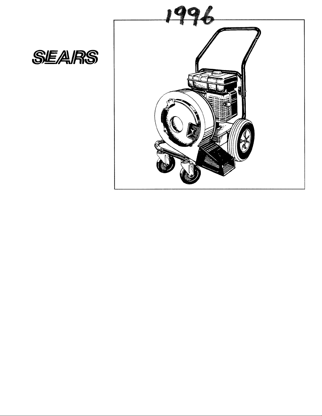
5 HORSEPOWER
AIR SWEEPER
Assembly
Operation
Customer Responsibilities
Service and Adjustment
Repair Parts
rited in U.S.A.
770-8839L 8/95
Page 2

IMPORTANT
THIS SYMBOL POINTS OUT IMPORTANT SAFETY INSTRUCTIONS WHICH, IF NOT FOLLOWED, COULD ENDANGER THE PERSON
AL SAFETY AND/OR PROPERTY OF YOURSELF AND OTHERS. READ AND FOLLOW ALL INSTRUCTIONS IN THIS MANUAL
A
A
BEFORE ATTEMPTING TO OPERATE YOUR AIR SWEEPER. FAILURE TO COMPLY WITH THESE INSTRUCTIONS MAY RESULT IN
PERSONAL INJURY. WHEN YOU SEE THIS SYMBOL: ^ HEED ITS WARNING.
Your air sweeper was built to be operated according to the rules tor safe operation in this manual. As with
DANGER: any type of power equipment, carelessness or error on the part of the operator can result in serious injury.
This unit is capable of amputating fingers and hands and throwing objects.
SAFE OPERATION PRACTICES
I. GENERAL OPERATION
i 1. Read this owner’s guide carefully in its entirety before
attempting to assemble this machine. Read, understand, and
follow all instructions on the machine and in the manual(s)
before operation. Be completely familiar with the controls and
the proper use of the machine before operating it. Keep this
manual in a safe place for future and regular reference and for
ordering replacement parts.
2. Your air sweeper is a powerful tool, not a plaything. Therefore,
exercise extreme caution at all times. Your unit has been
designed to perform one job; to blow leaves. Do not use it for
any other purpose.
3. Never allow children under 14 to operate the unit. Children 14
years and older should only operate under close parental
supervision. Only responsible individuals who are familiar with
these rules of safe operation should be allowed to use your
unit.
4. Keep the area of operation clear of all persons, particularly
small children and pets. Stop the engine when they are in the
vicinity of the unit.
5. Aiways wear safety glasses or safety goggles during operation
and while performing an adjustment or repair, to protect eyes
from debris or foreign objects that may be thrown from
machine.
6. Wear close fitting slacks and shirt. Shirt and slacks that cover
the arms and legs are recommended. Do not wear loose fitting
clothes or jewelry and secure hair so it is above shoulder
length. They can be caught in moving parts.
7. Do not operate the unit while under the influence of alcohol or
drugs.
8. Never place your hands or any part of your body or clothing
near rotating parts. Keep clear of the discharge opening at all
times. Never insert your hands, fingers, feet, or any other part
of your body or clothing into the discharge or air-intake open
ings as the rotating impeller inside the housing can cause seri
ous injury.
9. Never operate unit without directional discharge chute and
plastic impeller guard properly affixed to unit. These devices
shield the operator from accidental contact with the rotating
impeller.
10. Keep all guards and safety devices in place and operating prop
erly.
II. Exercise caution when operating blower. Do not allow the dis
charge to point in the direction of by-standers or pets.
12. if your machine should start making an unusual noise or vibra
tion, immediately stop the engine, disconnect the spark plug
wire and move the wire away from the spark plug. Allow the
machine to stop and take the following steps:
• Inspect for damage.
• Repair or replace any damaged parts.
• Check for any loose parts and tighten to assure continued
safe operation.
13. Muffler and engine become hot and can cause a burn. Do not
touch.
14. Do not allow leaves or other debris to build-up on engine’s
muffler. The debris could ignite and cause a fire.
15. Do not operate engine if air cleaner or cover over carburetor
air-intake is removed, except for adjustment. Removal of such
parts could create a fire hazard.
16. Only use accessories approved for this machine by the manu
facturer. Read, understand, and follow all instructions provid
ed with the approved accessory.
17. Only operate unit in good daylight. Do not operate unit at night
or in dark areas where your vision may be impaired.
18. If situations occur which are not covered by this manual, use
care and good judgment. Contact your dealer for assistance.
Jl. CHILDREN
Tragic accidents can occur if the operator is not alert to the presence
of small children. Children are often attracted to the blowing activity.
Never assume that children will remain where you last saw them.
1. Keep children out of the work area and under the watchful eye
of a responsible adult other than the operator.
2. Be alert and turn the unit off if a child enters the area.
3. Never allow children under the age of 14 to operate the air
sweeper.
,111. SERVICE
1. Use extreme care in handling gasoline and other fuels. They
are extremely flammable and the vapors are explosive.
a. Store fuel and oil in approved containers, away from heat
and open flame, and out of the reach of children.
b. Check and add fuel before starting the engine. Never
remove gas cap or add fuel while the engine is running.
Allow engine to cool at least two minutes before refueling.
c. Replace gasoline cap securely and wipe off any spilled
gasoline before starting the engine as it may cause a fire or
explosion.
d. Extinguish all cigarettes, cigars, pipes and other sources of
ignition.
e. Never refuel unit indoors because flammable vapors will
accumulate in the area.
f. Never store the machine or fuel container inside where
there is an open flame or spark such as a gas hot water
heater, clothes dryer or furnace.
2. Never run your machine in an enclosed area as the exhaust
from the engine contains carbon monoxide, which is an odor
less, tasteless and deadly poisonous gas.
3. To reduce fire hazard, keep engine and muffler free of leaves,
grass, and other debris build-up. Clean up fuel and oil spillage.
Allow unit to cool at least 5 minutes before storing.
4. Before cleaning, repairing, or inspecting, make certain the
impeller and all moving parts have stopped. Disconnect the
spark plug wire and keep wire away from spark plug to prevent
accidental starting. Do not use flammable solutions to clean
air filter.
5. Keep all nuts, bolts, and screws tight to be sure the equipment
is in safe working condition.
6. Never tamper with safety devices. Check their proper opera
tion regularly.
7. Do not alter or tamper with the engine’s governor setting. The
governor controls the maximum safe operating speed of the
engine. Over-speeding the engine is dangerous and will cause
damage to the engine and to other moving parts of the
machine.
Page 3

OWNER’S MANUAL
A
WARNING — YOUR RESPONSIBILITY
Restrict the use of this power machine to persons who read, understand and
follow the warnings and instructions in this manual and on the machine.
CONGRATULATIONS on your purchase of a Sears
Craftsman Air Sweeper. It has been designed, engineered
and manufactured to give you the best possible dependabil
ity and performance.
Should you experience any problem you cannot easily rem
edy, please contact your nearest Sears Service Center/
Department in the United States. We have competent, welltrained technicians and the proper tools to service or repair
this unit.
Please read and retain this manual. The instructions will
enable you to assemble and maintain your air sweeper
properly. Always observe the “SAFETY RULES.”
MODEL
NUMBER,
SERIAL
NUMBER,
DATE OF
PURCHASE.
THE MODEL AND SERIAL NUMBERS WILL BE FOUND
ON A LABEL ATTACHED TO THE FRAME OF THE AIR
SWEEPER.
YOU SHOULD RECORD BOTH SERIAL NUMBER AND
DATE OF PURCHASE AND KEEP IN A SAFE PLACE
FOR FUTURE REFERENCE.
247.797900
CUSTOMER RESPONSIBILITIES
Read and observe the safety rules.
Follow a regular schedule in maintaining, caring for
and using your air sweeper.
Follow the instructions under “Customer Respons
ibilities” and “Storage” sections of this Owner’s
Manual.
PRODUCT SPECIFICATIONS
Horsepower:
Displacement: 12.57 cu. in.
Fuel Capacity:
(Unleaded)
Engine Oil
API Classification SF, SG or SH
Spark Plug (Gap .030 in.):
Magnetron® Ignition Air Gap:
(20 ounces)
Champion
Equivalent)
5.0
1 Gallon
SAE 30
J19LM (or
.0125 in.
MAINTENANCE AGREEMENT
A Sears Maintenance Agreement is available on this
product. Contact your nearest Sears store for details.
WARNING: This unit is equipped with an internal combus
tion engine and should not be used on or near any unim
proved forest-covered, brush-covered or grass-covered land
unless the engine’s exhaust system is equipped with a
spark arrester meeting applicable local or state laws (if any).
If a spark arrester is used, it should be maintained in effec
tive working order by the operator.
In the State of California the above is required by law
(Section 4442 of the California Public Resources Code).
Other states may have similar laws. Federal laws apply on
federal lands. A spark arrester for the muffler is available
through your nearest Sears Authorized Service Center (See
the REPAIR PARTS section of this manual.)
WARRANTY
FULL ONE YEAR WARRANTY ON CRAFTSMAN POWER BLOWER
For one year from the date of purchase, when this Craftsman power blower is maintained, lubricated, and tuned
up according to the operating and maintenance instructions in the operator’s manual. Sears will repair, free of
charge, any defect in material or workmanship.
This warranty excludes the spark plug and air cleaner, which are expendable parts and become worn during
normal use.
if this power blower is used for commercial or rental purposes, this warranty applies for only 30 days from the
date of purchase.
WARRANTY SERVICE IS AVAILABLE BY CONTACTING THE NEAREST SEARS SERVICE CENTER IN THE
UNITED STATES. THIS WARRANTY APPLIES ONLY WHILE THIS PRODUCT IS IN USE IN THE UNITED
STATES.
This warranty gives you specific legal rights, and you may also have other rights which vary from state to state.
SEARS ROEBUCK AND CO., DEPT. 817WA, HOFFMAN ESTATES, IL 60179
Page 4
TABLE OF CONTENTS
SAFETY RULES
PRODUCT SPECIFICATIONS.............
WARRANTY
INDEX
....................................
ASSEMBLY
OPERATION
CUSTOMER RESPONSIBILITIES ........................10, 11
Accessories..........................
Adjustments: Agreement
Carburetor........................
Engine Speed
Throttle
Assembly Instructions
Controls
Customer Responsibilities.................
Engine:
Fuel
Lubrication
................................
Maintenance
Starting
Stopping...........................
Storage
........................................
...................
..........................
...........................
.........................
A
..................
.............................
.......
C
E
....................
.............................
.............................
F
L
...........................
.................................
.................................
.................................
.................................
.............................5, 6
..............................7-9
.................................
...............................
...............................
...............................
.............................5, 6
.................................
...................
........................10, 11
.................................
.................................
...............................
.................................
...............................
3, 10, 11
2
3
3
4
4
13
13
13
7
9
8
12
8
10
STORAGE
SERVICE AND ADJUSTMENT
TROUBLE SHOOTING..
PARTS ORDERING/SERVICE
REPAIR PARTS—AIR SWEEPER
REPAIR PARTS—ENGINE
INDEX
Maintenance:
Air Sweeper
Schedule
Engine
Oil.........................................
Repair/Replacement Parts
Responsibilities, Customer
Safety Rules
Service Recommendations...........................
Spark Plug..........................
Specifications
Storage
Table of Contents..............
Trouble Shooting
Unpacking
Warranty
...........................
........................
............................
...............................
..........................
............................
....................
...................
.......................
....................
..............
.......................
.......................
................
.............................
M
0
R
............................
..........................
S
T
u
w
....................
....................
....................
....................
.............
..............
......................
....................
....................
.............
...............
..............
...........
.......................2
....................
....................
......................
....................
.......................4
....................
.......................5
.......................3
12
13
14
14
15, 16
17-21
10
10
10, 11
8, 10
15-21
3, 9, 10
10
11
12
14
3
3
AIR SWEEPER ACCESSORIES
These accessories were available when the air sweeper was
purchased. They are also available at most Sears retail outlets, catalog
and service centers. Most Sears stores can order repair parts for you,
when you provide the model number of your air sweeper.
ENGINE
AIR SWEEPER
Page 5
ASSEMBLY INSTRUCTIONS
IMPORTANT: This unit is shipped WITHOUT GASO
LINE or OIL. After assembly, see operation section of
this manual for proper fuel and engine oil recommen
dations.
NOTE: To determine right and left hand side of your
air sweeper, stand behind the handle in the operating
position.
UNPACKING
Your air sweeper, has been completely assembled at
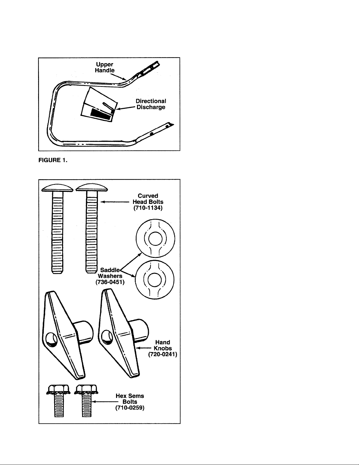
the factory except for the upper handle and directional
discharge. See figure 1. The hardware pack is also
-included in the carton. The hardware pack contains
parts shown in figure 2.
• Remove staples or break glue on the top flaps of
the carton.
• Cut carton down along each corner and lay carton
down flat. Roll air sweeper out of the carton.
• Make certain all parts and literature have been
removed before the carton is discarded.
TOOLS REQUIRED FOR ASSEMBLY
(1 ) 1/2" or Adjustable Wrench
FIGURE 2.
Page 6
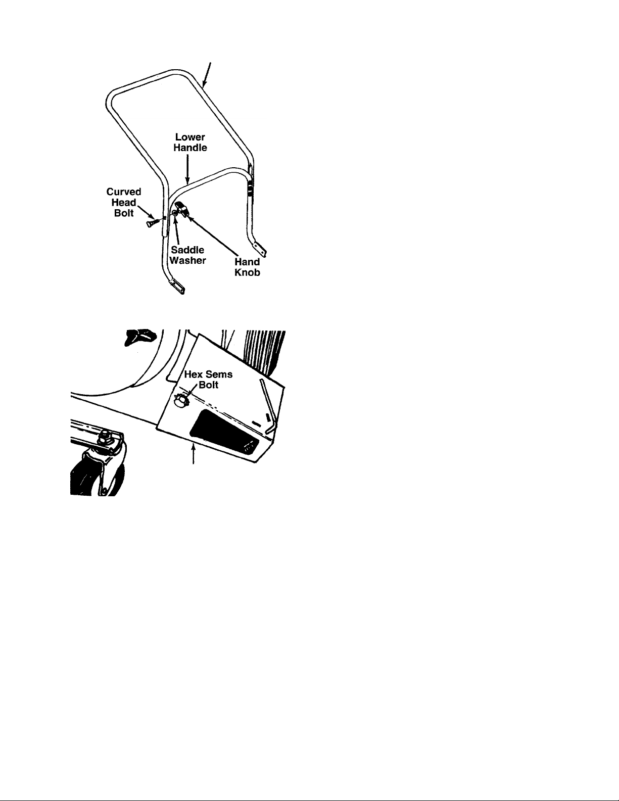
FIGURE 3.
Upper Handle
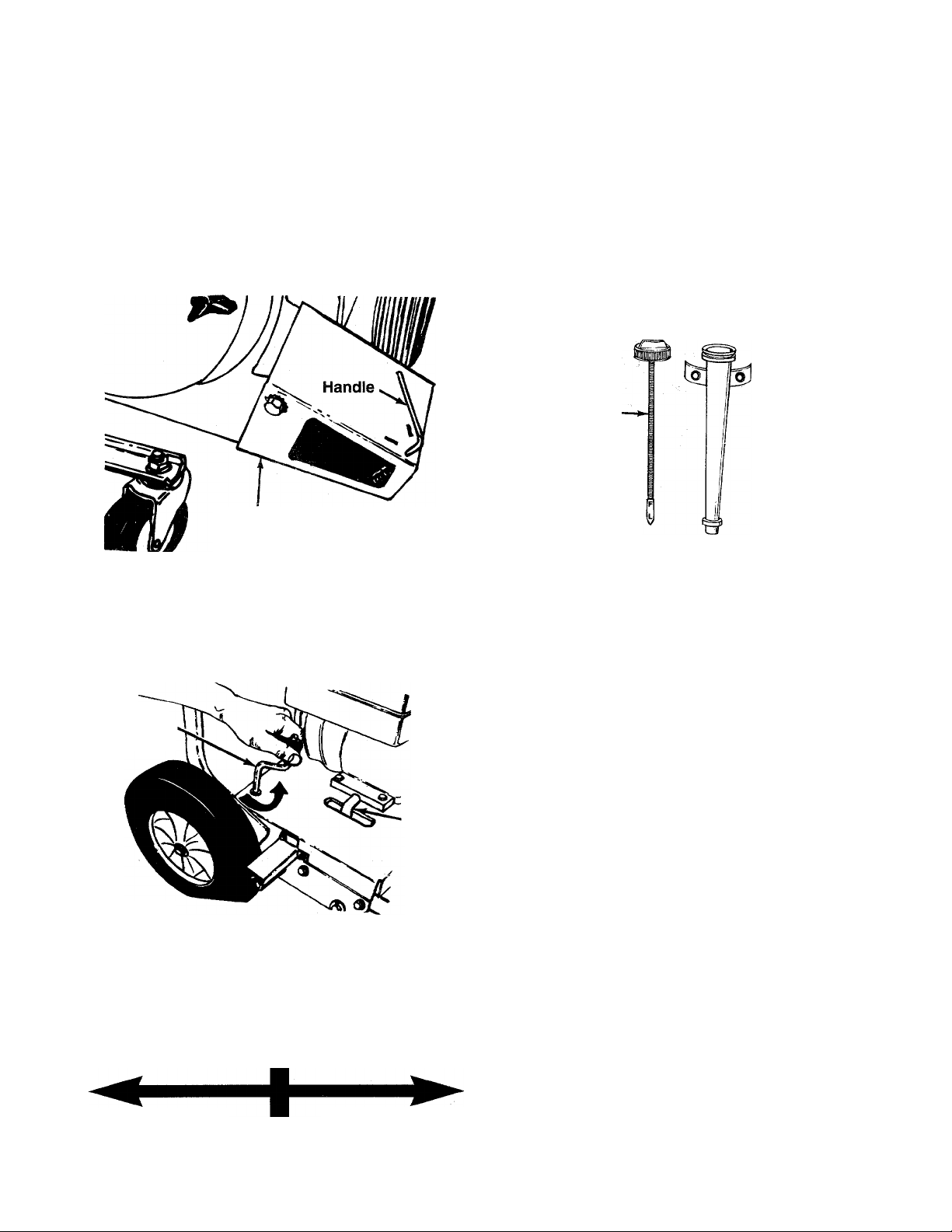
HOW TO SET-UP YOUR AIR SWEEPER
ATTACHING THE UPPER HANDLE
Place the upper handle over the lower handle, lining
up the holes in the upper handle with the middle
holes In lower handle. Secure with curved head bolts,
■saddle washers and hand knobs. See figure 3.
FIGURE 4.
ATTACHING THE DIRECTIONAL DISCHARGE
Slip end of directional discharge over chute opening.
- Secure in position with hex sems bolts. See figure 4.
Directional
Discharge
Page 7
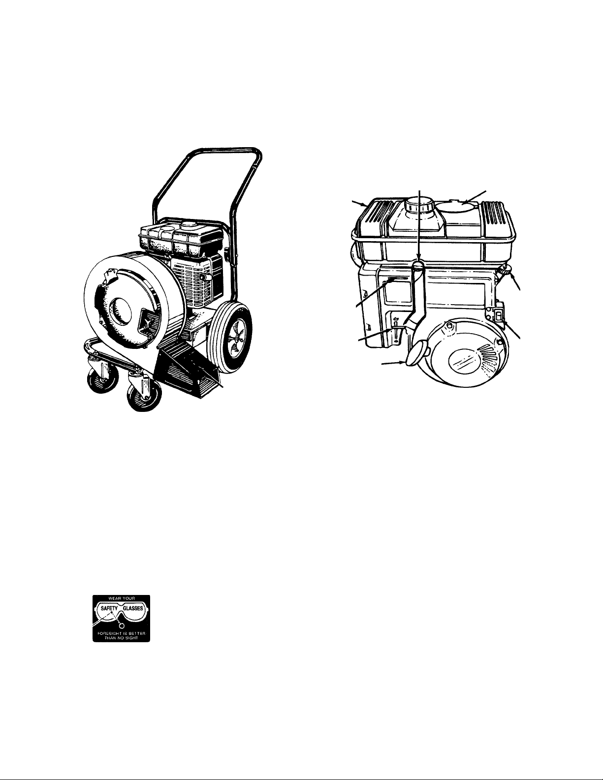
OPERATION
KNOW YOUR AIR SWEEPER
READ THIS OWNER’S MANUAL AND SAFETY RULES BEFORE OPERATING YOUR AIR SWEEPER.
Compare the illustrations with your air sweeper to familiarize yourself with the location of various controls and
adjustments. Save this manual for future reference.
Directional
Discharge
FIGURE 5.
Handle
OPERATING CONTROLS (See figure 5)
DIRECTIONAL DISCHARGE HANDLE—Used to
change the direction in which air is discharged to the
front or to the side.
CHOKE LEVER—Used to enrich the fuel mixture in
the carburetor when starting a cold engine.
STARTER HANDLE—Used to manually start the
engine.
Fuel
Shut-Off
Fuel
Tank*
Choke/
Lever
Throttle
Control
Starter
Handle
ENGINE SHUT-OFF SWITCH—Used to stop the
engine.
FUEL SHUT-OFF VALVE—Used to stop the flow of
fuel into the carburetor.
THROTTLE CONTROL—Permits selection of fast or
slow engine speed.
Valve
Spark Plug,
Wire and Boot
(Under Cover)
Oil Fill
Dipstick
Engine
Shut-Off
Switch
BEFORE USING YOUR AIR SWEEPER AGAIN REFER TO THE
OF THIS MANUAL. ALWAYS BE CAREFUL.
The operation of any air sweeper can result in foreign objects being thrown into the
eyes, which can result in severe eye damage. Always wear safety glasses before
starting power tool operation or while performing any adjustments or repairs. We rec
ommend Wide Vision Safety Mask for over spectacles or standard glasses available
at Sears Retail or Catalog Stores.
TO STOP ENGINE
• Move throttle control lever to SLOW position.
• Move engine shut-off switch to OFF position. See
figure 5.
Disconnect spark plug wire and move away from
spark plug to prevent accidental starting while
equipment is unattended.
Close fuel shut-off valve when equipment is not in
use to prevent fuel leakage.
‘SAFETY RULES” AS SHOWN ON PAGE 2
Page 8
HOW TO USE YOUR AIR SWEEPER
WARNING: DO NOT AT ANY TIME MAKE
ANY ADJUSTMENT TO THE UNIT WITH
A
TWO-WAY DISCHARGE
The air sweeper can be adjusted to discharge toward
the front of the unit or to the side. Simply push down
on the handle and swing door toward the front to dis
charge out the side, or to the side to discharge out the
front. See figure 6.
FIGURE 6.
HEIGHT ADJUSTMENT
The height adjustment crank is located on the right
hand side of the air sweeper. See figure 7. Turn the
crank clockwise to raise the discharge chute. Turn the
crank counterclockwise to lower.
Adjustment
FIGURE 7.
OUT FIRST STOPPING ENGINE AND DIS
CONNECTING SPARK PLUG WIRE.
Directional
Discharge
Height
Crank
Oil
Drain
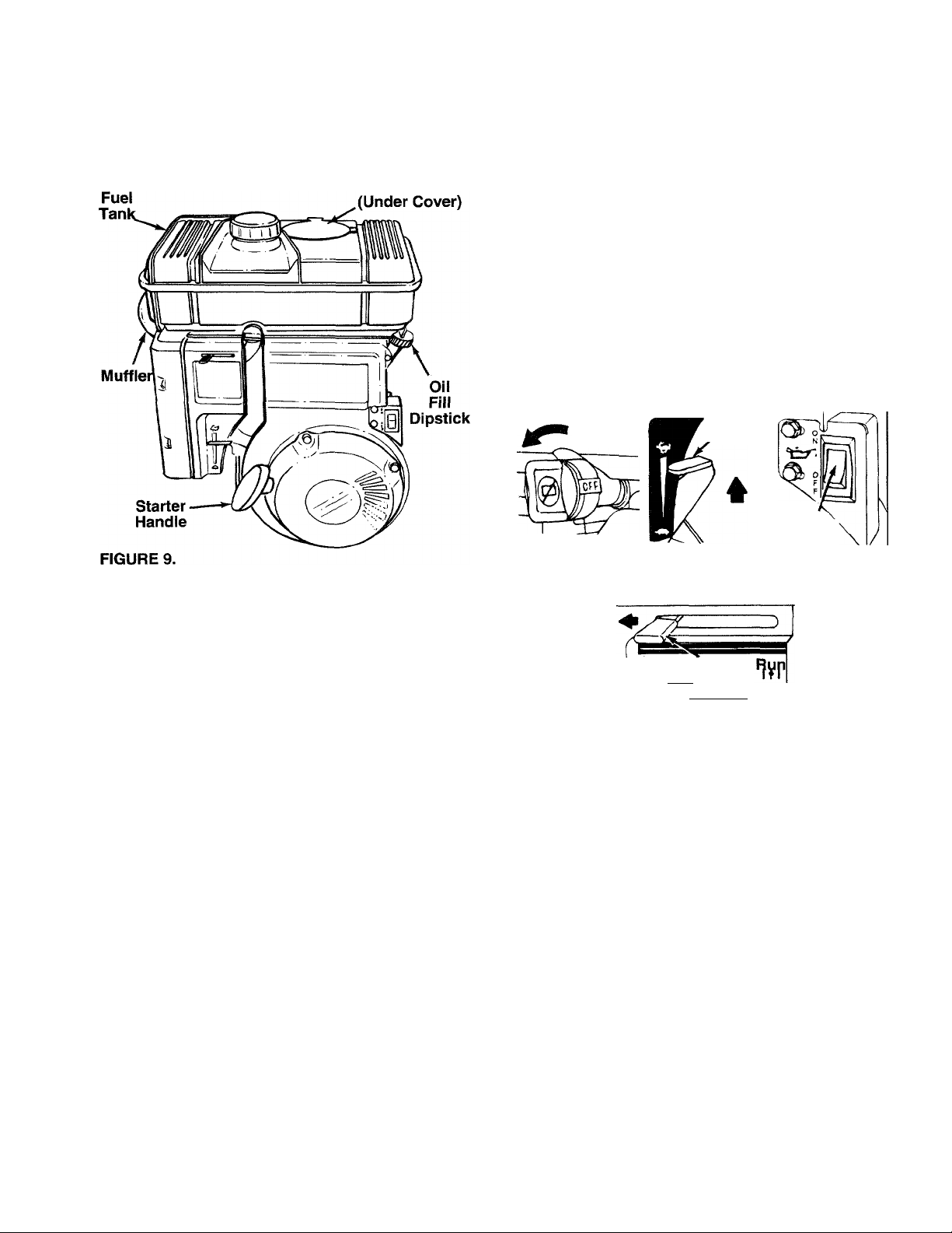
GAS AND OIL FILL-UP
OIL
Only use high quality detergent oil rated with API ser
vice classification SF, SG or SH. Select the oil’s vis
cosity grade according to your expected operating
temperature.
Colder
------------------------
5W30
32°F
-----------------
SAE 30
► Warmer
NOTE: Although multi-viscosity oils (5W30, 10W30,
etc.) improve starting in cold weather, these multi
viscosity oils will result in increased oil consumption
when used above 32°F. Check your oil level more fre
quently to avoid possible engine damage from run
ning low on oil.
• Fill engine with oil as follows. Remove oil fill dip
stick. See figure 8. With air sweeper level, use a
funnel to fill engine with oil to FULL mark on dip
stick. Capacity is approximately 1-1/4 pints. Be
careful not to overfill. Tilt air sweeper toward the
left, then re-level. Check oil level. Refill to FULL
mark on dipstick if necessary. Replace dipstick and
tighten.
Oil
Fill
Dipstick
FIGURE 8.
GAS
• Remove fuel cap and fill fuel tank with about 1 gal
lon of clean, fresh, lead-free grade automotive
gasoline. DO NOT use Ethyl or high octane gaso
line. Be certain container is clean and free from
rust or foreign particles. Never use gasoline that
may be stale from long periods of storage in the
container. Replace fuel cap.
WARNING: DO NOT FILL CLOSER THAN
1/2 INCH OF TOP OF FUEL TANK TO
A
WARNING: EXPERIENCE INDICATES THAT ALCO
HOL BLENDED FUELS (CALLED GASOHOL OR
USING ETHANOL OR METHANOL) CAN ATTRACT
MOISTURE WHICH LEADS TO SEPARATION AND
FORMATION OF ACIDS DURING STORAGE.
ACIDIC GAS CAN DAMAGE THE FUEL SYSTEM
OF AN ENGINE WHILE IN STORAGE. TO AVOID
ENGINE PROBLEMS, THE FUEL SYSTEM
SHOULD BE EMPTIED OR TREATED WITH FUEL
STABILIZER BEFORE STORAGE FOR 30 DAYS
OR LONGER. USE FRESH FUEL NEXT SEASON.
SEE “STORAGE ’ SECTION FOR ADDITIONAL
INFORMATION.
PREVENT SPILLS AND TO ALLOW FOR
FUEL EXPANSION. IF GASOLINE IS
ACCIDENTLY SPILLED, MOVE AIR
SWEEPER AWAY FROM AREA OF
SPILL. AVOID CREATING ANY SOURCE
OF IGNITION UNTIL GASOLINE VAPORS
HAVE DISAPPEARED.
Page 9
NEVER USE ENGINE OR CARBURETOR CLEAN
ER PRODUCTS IN THE FUEL TANK OR PERMA
NENT DAMAGE MAY OCCUR.
Spark Plug,
• Grasp starter handle (see figure 9) and pull rope
out slowly until engine reaches start of compres
sion cycle (rope will pull slightly harder at this
point). Let the rope rewind slowly.
• Pull rope with a rapid, continuous, full arm stroke.
Keep a firm grip on starter handle. Let rope rewind
slowly. Do not let starter handle snap back against
starter.
• Repeat preceding two instructions until engine
fires. When engine starts, move choke lever on
engine halfway between CHOKE and RUN.
NOTE: If engine does not fire after three attempts,
move choke lever halfway between CHOKE and RUN
position and try again. See figure 10.
TO START ENGINE
WARNING: DO NOT OPERATE THIS AIR
SWEEPER UNLESS THE DIRECTIONAL
A
• Open cover (on top of fuel tank) and attach spark
plug wire and rubber boot to spark plug if neces
sary. See figure 9.
• Open fuel shut-off valve by turning in direction of
arrow. See figure 10.
• Place the throttle control lever in FAST position.
NOTE: If the throttle control lever fails to stay in the
desired position or if it is hard to move, refer to the
service and adjustment section.
• Move choke lever down to CHOKE position.
• Place the engine shut-off switch in ON position.
DISCHARGE HAS BEEN PROPERLY
INSTALLED AND IS SECURED. REVOLV
ING BLADES—KEEP HANDS AWAY
FROM ALL OPENINGS.
See figure 10.
See figure 10.
On
Position
Fuei Shut-Off
Vaive
?№ Choke
FÌGURE10.
Fast
Position
Throttie
Position
CHOKE
On
Position'
Engine Shut-Off
Switch
TO STOP ENGINE
• Move throttle control lever to SLOW position.
• Move engine shut-off switch to OFF position. See
figure 10.
• Disconnect spark plug wire and move away from
spark plug to prevent accidental starting while
equipment is unattended.
• Close fuel shut-off valve when equipment is not in
use to prevent fuel leakage.
Page 10
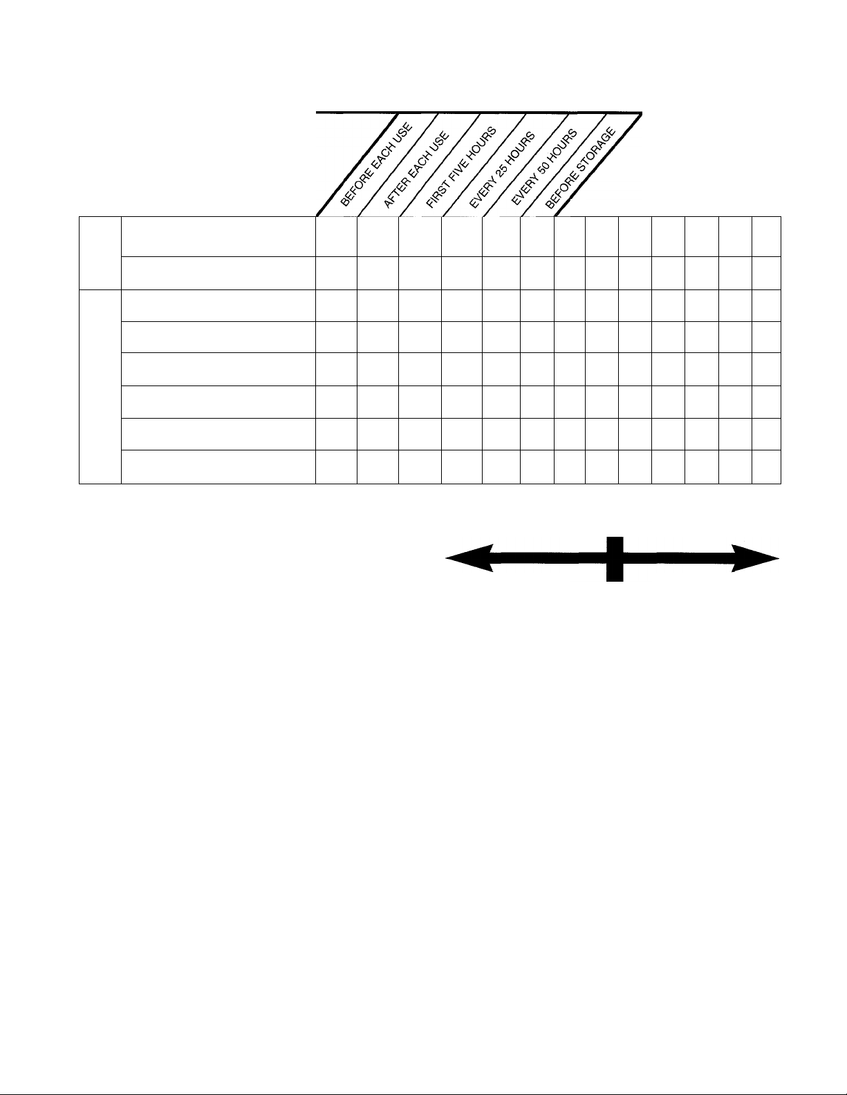
CUSTOMER RESPONSIBILITIES
MAINTENANCE SCHEDULE
FILL IN DATES
AS YOU COMPLETE
REGULAR SERVICE
ho
Oil Pivot Points
=)
o
o
cc
Clean Air Sweeper
CL
SERVICE DATES
a/
V
a/
UJ
z
(5
z
lU
V CHECK
Check Engine Oil
Change Engine Oil
Service Air Cleaner
Clean Engine Cylinder
Spark Plug
Muffler
V
GENERAL RECOMMENDATIONS
WARNING: ALWAYS STOP THE ENGINE
AND DISCONNECT THE SPARK PLUG
A
• Periodically check all fasteners and be sure they
are tight.
• Follow the Maintenance Schedule above.
WIRE BEFORE PERFORMING ANY
MAINTENANCE OR ADJUSTMENTS.
AIR SWEEPER
LUBRICATION
• Lubricate the pivot points and the spring on the
directional discharge at least once a season using
a light oil.
CLEANING
• The air sweeper may be cleaned by running water
from a hose through the hopper assembly and
chipper chute with the engine running. Allow the air
sweeper to dry thoroughly.
ENGINE
ENGINE OIL
Only use high quality detergent oil rated with API ser
vice classification SF, SG or SH. Select the oil's vis
cosity grade according to your expected operating
temperature.
V
V
V
V
a/
Colder
NOTE: Although multi-viscosity oils (SAE30, 10W30,
etc.) improve starting in cold weather, these multi- vis
cosity oils will result in increased oil consumption
when used above 32°F. Check your oil level more fre
quently to avoid possible engine damage from run
ning low on oil.
Your four-cycle engine will normally consume some
oil—therefore, check engine oil level regularly approx
imately every five hours of operation and before each
usage. Stop engine and wait several minutes before
checking oil level. With engine level, the oil must be to
FULL mark on dipstick (refer to figure 8). Change
engine oil after the first five hours of operation, and
every twenty-five hours thereafter.
To Drain Oil:
• Drain oil while engine is warm.
a. Remove oil drain plug. Refer to figure 7. Catch
oil in a suitable container.
b. When engine is drained of all oil, replace drain
plug securely.
• Refill with fresh oil. Refer to GAS AND OIL FILL
UP section.
• Replace dipstick.
a/
V
a/
32°F Warmer
5W30
SAE 30
10
Page 11
AIR CLEANER
The air cleaner prevents damaging dirt, dust, etc.,
from entering the carburetor and being forced into the
engine and is important to engine life and per
formance.
Never run your engine without air cleaner com
pletely assembled.
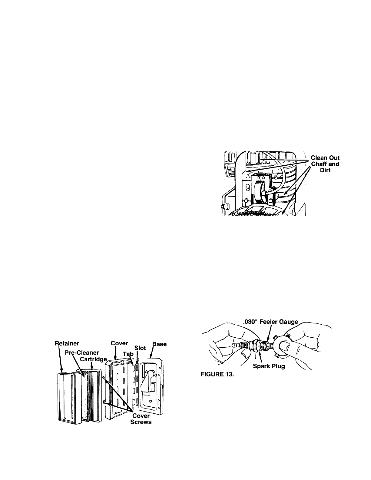
To Service Air Cleaner:
Service pre-cleaner after every 25 hours of use, or at
least once a season. Service cartridge every 100 hours
of use, or at least once a season. Service pre-cleaner
and cartridge more often under dusty conditions.
• Loosen air cleaner cover screws. Remove cover
and air cleaner assembly from base. See figure 11.
• Remove air cleaner assembly from inside cover
and disassemble.
• To service foam pre-cleaner: Remove pre-cleaner.
Wash in liquid detergent and water. Squeeze dry in
a clean cloth. Saturate in engine oil. Squeeze in a
clean, absorbent cloth to remove all excess oil. If
pre-cleaner is very dirty, replace it.
• To service cartridge: Clean by tapping gently on a
flat surface. If very dirty, replace. Do not oil cartridge.
NOTE: Do not use petroleum solvents (e.g. kerosene)
or pressurized air to clean cartridge. They will cause
cartridge to deteriorate.
• Reassemble retainer on pre-cleaner and cartridge
(screen side of pre-cleaner toward cartridge
pleats). Place assembly into cover.
• Insert tabs on cover into slots in base and tighten
cover screws securely.
CLEAN ENGINE
Clean engine periodically. Remove dirt and debris
with a cloth or brush. Cleaning with a forceful spray of
water is not recommended as water could contami
nate the fuel system.
Yearly or every 25 hours, whichever occurs first,
remove the blower housing and clean the areas
shown in figure 12 to avoid overspeeding, overheating
and engine damage. Clean more often if necessary.
WARNING: PERIODICALLY CLEAN MUF
FLER AREA TO REMOVE ALL GRASS,
A.
FIGURE 12.
SPARK PLUG
The spark plug should be cleaned and the gap reset
to .030" at least once a season or every 50 hours of
operation. See figure 13. Spark plug replacement is
recommended at the start of each season. Refer to
engine parts list for correct spark plug type.
NOTE: Do not sandblast spark plug. Spark plug
should be cleaned by scraping or wire brushing and
washing with a commercial solvent.
DIRT AND COMBUSTIBLE DEBRIS.
FIGURE 11.
MUFFLER
Do not operate the air sweeper without a muffler or
tamper with the exhaust system. Damaged mufflers or
spark arresters could create a fire hazard. Inspect
periodically, and replace if necessary. If your engine
is equipped with a spark arrester screen assembly,
remove every 50 hours for cleaning and inspection.
Replace if damaged.
11
Page 12

STORAGE
Prepare your air sweeper for storage at the end of the
season or if the unit will not be used for 30 days or
more.
WARNING: NEVER STORE MACHINE
WITH FUEL IN THE FUEL TANK INSIDE
A
NOTE: A yearly check-up by your local Sears Service
Center is a good way to make certain your air
sweeper will provide maximum performance for the
next season.
OF BUILDING WHERE FUMES MAY
REACH AN OPEN FLAME OR SPARK, OR
WHERE IGNITION SOURCES ARE
PRESENT SUCH AS HOT WATER AND
SPACE HEATERS, FURNACES, CLOTHES
DRYERS, STOVES, ELECTRIC MOTORS,
ETC.
AIR SWEEPER
• Clean the air sweeper thoroughly.
• Wipe unit with an oiled rag to prevent rust (use a
light oil or silicone).
ENGINE
IMPORTANT: IT IS IMPORTANT TO PREVENT
GUM DEPOSITS FROM FORMING IN ESSENTIAL
FUEL SYSTEM PARTS SUCH AS CARBURETOR,
FUEL FILTER, FUEL HOSE, OR TANK DURING
STORAGE. ALSO, EXPERIENCE INDICATES THAT
ALCOHOL BLENDED FUELS (CALLED GASOHOL
OR USING ETHANOL OR METHANOL) CAN
ATTRACT MOISTURE WHICH LEADS TO SEPARA
TION AND FORMATION OF ACIDS DURING STOR
AGE. ACIDIC GAS CAN DAMAGE THE FUEL SYS
TEM OF AN ENGINE WHILE IN STORAGE.
• Drain the fuel tank.
• Start the engine and let it run until the fuel lines and
carburetor are empty.
• Never use engine or carburetor cleaner products in
the fuel tank or permanent damage may occur.
• Use fresh fuel next season.
NOTE: Fuel stabilizer is an acceptable alternative in
minimizing the formation of fuel gum deposits during
storage. Add stabilizer to gasoline in fuel tank or stor
age container. Always follow the mix ratio found on
stabilizer container. Run engine at least 10 minutes
after adding stabilizer to allow the stabilizer to reach
the carburetor. Do not drain the gas tank and carbure
tor if using fuel stabilizer.
• Drain all the oil from the crankcase (this should be
done after the engine has been operated and is still
warm) and refill the crankcase with fresh oil.
• If you have drained the fuel tank, protect the inside
of the engine as follows. Remove spark plug, pour
approximately 1/2 ounce (approximately one table
spoon) of engine oil into cylinder and crank slowly
to distribute oil. Replace spark plug.
OTHER
• Do not store gasoline from one season to another.
• Replace your gasoline can if your can starts to rust.
Rust and/or dirt in your gasoline will cause problems.
• Store unit in a clean, dry area. Do not store next to
corrosive materials, such as fertilizer.
NOTE: If storing in an unventilated or metal storage
shed, be certain to rustproof the equipment by coating
with a light oil or silicone.
12
Page 13

SERVICE & ADJUSTMENT
WARNING: ALWAYS STOP ENGINE AND
DISCONNECT SPARK PLUG WIRE AND
A
MOVE IT AWAY FROM SPARK PLUG
BEFORE PERFORMING ANY ADJUST
MENTS OR REPAIRS.
THROTTLE ADJUSTMENT
To adjust throttle control lever, loosen or tighten wing
nut until throttle control lever moves with some resis
tance and still remains in desired position when
engine is running. See figure 14.
Throttle
Control
Lever
The carburetor may need re-adjusting if engine lacks
power or does not idle properly. If adjustments are
needed, proceed as follows.
• Close idle mixture valve (see figure 15) clockwise
() finger tight only. Forcing may cause damage.
Then open 1-1/2 turns counterclockwise ().
• Start engine and allow to warm for five minutes.
• Move throttle control lever to IDLE position.
• Rotate throttle counterclockwise (i^ ) and hold
against idle speed adjusting screw. Turn idle speed
adjusting screw until engine is running at 1750
RPM.
• Turn idle mixture valve clockwise () (lean mix
ture) until engine JUST starts to slow. Then turn it
counterclockwise ((rich mixture) until engine
starts to run unevenly. Set at midpoint between rich
and lean mixture.
• Recheck idle RPM and readjust if necessary.
• Move throttle control lever to FAST position.
Engine should accelerate without hesitation or
sputtering. If it does not, carburetor should be read
justed, usually to a slightly richer mixture.
FIGURE 14.
CARBURETOR ADJUSTMENT
WARNING: IF ANY ADJUSTMENTS ARE
MADE TO THE ENGINE WHILE THE
A
Minor carburetor adjustment may be required to com
pensate for differences in fuel, temperature, altitude
or load.
NOTE: A dirty air cleaner will cause engine to run
rough. Be certain air cleaner is clean and attached to
the carburetor before adjusting carburetor. Do not
make unnecessary adjustments. Factory settings are
satisfactory for most applications and conditions.
Never attempt to change maximum engine speed. It is
pre-set at the factory and should be changed only by
a qualified service technician who has the necessary
equipment.
ENGINE IS RUNNING (E.G. CARBURE
TOR), KEEP CLEAR OF ALL MOVING
PARTS. BE CAREFUL OF HEATED SUR
FACES AND MUFFLER.
ENGINE SPEED
Your engine speed has been factory set. Do not
attempt to increase engine speed or it may result in
personal injury. If you believe the engine is running
too fast or too slow, take your air sweeper to the
nearest SEARS Service Center for repair and adjust
ment.
13
Page 14

TROUBLE SHOOTING
PROBLEM POSSIBLE CAUSE(S)
Engine fails to start • Engine shut-off switch OFF.
Loss of power; • Spark plug wire loose.
operation erratic • Unit running on CHOKE.
Engine overheats • Carburetor not adjusted properly.
Too much vibration • Loose parts or damaged
Unit does not
discharge
• Fuel shut-off valve closed.
• Fuel tank empty, or stale fuel.
• Spark plug wire disconnected. • Connect wire to spark plug.
• Faulty spark plug.
• Biocked fuel line or stale fuel.
• Water or dirt in fuel system.
• Carburetor out of adjustment.
• Dirty air cleaner.
• Engine oil level low.
• Air flow restricted.
crankshaft.
• Directional discharge clogged.
• Foreign object lodged in air vane
plate assembly.
CORRECTIVE ACTION
• Move switch to ON position.
• Open fuel shut-off valve.
• Fill tank with clean, fresh fuel.
• Clean, adjust gap or replace.
• Connect and tighten spark plug wire.
• Move choke lever to OFF position.
• Clean fuel line; fill tank with clean fresh gasoline.
• Disconnect fuel line at carburetor to drain fuel
tank. Refill with fresh fuel.
• Adjust carburetor or contact your SEARS Service Center.
• Service air cleaner. See Customer Responsibilities
section of this manual.
• Contact your SEARS Service Center.
• Fill crankcase with proper oil.
• Remove blower housing and clean.
• Stop engine immediately and disconnect
spark plug wire. Tighten all bolts and nuts.
Make all necessary repairs. If vibration continues,
have unit serviced by a SEARS Service Center.
• Stop engine immediately and disconnect
spark plug wire. Clean discharge area and inside
of blower housing.
• Stop engine immediately and disconnect
spark plug wire. Remove lodged object.
NOTE: For repairs beyond the minor adjustments listed above, please contact your nearest SEARS Service Center.
HOW TO ORDER REPLACEMENT PARTS
Each air sweeper has its own model number. Each
engine has its own model number.
The model number for your air sweeper will be found
on a label attached to the frame.
The model number for the engine will be found on the
blower housing of the engine.
All parts listed herein may be ordered through Sears,
Roebuck and Co. Service Centers and most Retail
Stores.
WHEN ORDERING REPAIR PARTS, ALWAYS GIVE
THE FOLLOWING INFORMATION:
‘PRODUCT - “5 H.P. Air Sweeper”
‘MODEL NUMBER - 247.797900
‘ENGINE MODEL NO. -133412-0059-01
‘PART NUMBER
‘PART DESCRIPTION
Your Sears merchandise has added value when you
consider that Sears has service units nationwide
staffed with Sears trained technicians...professional
technicians specifically trained on Sears products,
having the parts, tools and the equipment to ensure
that we meet our pledge to you...“we service what we
sell.”
14
Page 15

SEARS CRAFTSMAN 5 H.P. AIR SWEEPER MODEL NO. 247.797900
Repair Parts
REF.
NO.
PART
NO.
1 749-0784
2 726-0100
720-0171
3
736-0117
4
133412-0059-01
5
710-0442
6
7 16453
736-0119
8
712-0267
9
736-0187
10
11 714-0115
12 712-0206
736-0921
13
14 734-1036
15 16273
710-0726
16
17 14529
747-0542
18
DESCRIPTION
Upper Handle
Push Nut 3/8" Rod
REF.
NO.
20
21 710-0170
Crank Knob
FI-Wash. .385" I.D. x .62"
22 736-0162
Engine—B&S 133412-0059-01 23
Hex Bolt 5/16-18 X 1.50" Lg.‘
24 750-0528
Engine Mounting Frame Ass’y.
L-Wash. 5/16" I.D.*
Hex Nut 5/16-18 Thd.*
FI-Wash. .63" I.D. X 1.25"
Cotter Pin 1/8" Dia. x 1.0"
Hex Nut 1/2-13 Thd.*
25
26
27 710-0118
28
29 09966
L-Wash. 1/2" I.D.* 30
Swivel Caster Wheel 5" Dia. 31
X 1.25"
Caster Arm Ass’y.
Hex Wash. Hd. “AB” Tap Scr.
5/16" X .75" Lg.
Caster Arm Bracket
32 734-1035
33 751-0596
34 710-0227 Hex Wash. Hd. AB-Tap Scr.
—
Height Adjustment Crank
PART
NO.
736-0159
FI-Wash. .34" I.D. x .87" O.D.
DESCRIPTION
Hex Locking Bolt 5/16-24 x
.64" Lg.
Fi-Wash.
736-0300
FI-Wash. .38" I.D. x .57"
Spacer .382" I.D. x .50"
X.180" Lg.
736-0169
L-Wash. 3/8" I.D.*
712-0354 Hex Nut 3/8-8 Thd.
Hex Bolt 5/16-18 X.75" Lg.*
711-0797 Ferrule
Hand Knob
710-0487 Carriage Bolt 5/16-18 x 2.0"
749-0785 Lower Handle
Wheel Ass’y. Comp. 12" x 3"
Outlet Pipe
#8 X .5" Lg.
770-8839L Owner’s Manual
‘Common Hardware—May Be Purchased Locally. NOTE: Specifications subject to change without
notice or obligation.
15
Page 16

SEARS CRAFTSMAN 5 H.R AIR SWEEPER MODEL NO. 247.797900
Repair Parts
KEY
NO.
PART
NO.
1
14539
2
710-0600 Hex Self-Tap Scr. 5/16" x .5"
3
710-0118
4
736-0119 L-Wash. 5/16" I.D.* 17 736-0217
14541
5
6 710-0627
7
710-0260 Carriage Bolt 5/16-18 x .62" 22
Engine Housing Brace Ass’y.
Hex Bolt 5/16-18 X.75" Lg.* 16 710-0191 Hex Bolt 3/8-24 x 1.25"*
Right Angle Bracket
Hex Locking Bolt 5/16-24 x .75"
DESCRIPTION
KEY
NO.
14
15 14563 Nozzle Plate Ass’y.
18 681-0075 Air Vane Plate Ass’y.
19
8 14479 Directional Discharge Ass’y.
11
736-0119 L-Wash. 5/16" I.D.*
12 712-0267
Hex Nut 5/16-18 Thd.* 24 720-0170
23
13 731-0608 Blower Guard
*Common Hardware—May Be Purchased Locally.
16
PART
NO.
DESCRIPTION
711-0758 Hex Shoulder Nut .50" I.D.
L-Wash. 3/8" I.D.-H.D.
14496A
Blower Housing Ass’y.-Comp.
710-0259 Hex Sems Bolt 5/16-18 x .62"
736-0242
Lg*
Bell-Wash. .34" I.D. x .87" O.D.
3-Arm Thumb Scr. 5/16-18 x .75“
Lg.
Page 17

BRIGGS AND STRATTON 5 H.P. ENGINE MODEL NO. 133412-0059-01
Repair Parts
11
REF.
NO.
1
2 399268
3
5
7
8
9
10
11 66578
13
13A
14 94679
15
200
227 494906
230
305A 94619
306
307 94680
308
337
383
528
552
562
592
614 93306
615
616
635
869
870
871 262001
978
979
982
1019
PART
NO.
495133
*299819
214040
*272157
495774
*27549
94621
94221
94167
94387
223886 Guide—Air
94742
224820
224740
802592 Plug—Spark
89838
231818
231079
92613
231082 Nut—Hex
93307
231077
66538
211787
211436
*271736
494807 Cover—Oil Gard®
94658
495861
Cylinder Assembly
Bushing—Cylinder
Seal—Oil
Head—Cylinder
Gasket—Cylinder Head
Breather—Valve Chamber
Gasket—Valve Cover
Screw—Breather Mtg.
Grommet—Breather Tube
Screw—Cylinder Head (2-5/16"
Stud—Cylinder Head
Screw—Cylinder Head (2-15/32"
Plug—Pipe, 1/4" Std., Square Head
Lever Ass’y—Governor
Washer—Governor Lever
Screw—Hex Hd.
Shield—Cylinder
Screw—Cylinder Shield
Cover—Cylinder Head
Wrench—Spark Plug
Tube—Breather
Bushing—Governor Crank
Bolt—Governor Lever
Cotter-Pin
Retainer—E-Ring
Crank—Governor
Elbow—Spark Plug
Seat—Intake Valve
Seat—Exhaust Valve (Cobalite®)
Guide—Exhaust Valve
Note: 63709 Guide—Intake
Valve.
Gasket—Cover
Screw—Oil Gard® Cover
Label Kit
DESCRIPTION
Long)
Long)
528^
If 614
230 615
305A
REQUIRES SPECIAL TOOLS
TO INSTALL. SEE REPAIR
INSTRUCTION MANUAL.
984
REF.
NO.
75
98A
165
201
209
222 494899
232 260585
284 94620
346
347 493521
663
984 224746
Included in Gasket Set—Part No. 495661.
PART
NO.
495659
493280 Screw Ass’y.—Speed Adj.
94692 Nut—Wing
262865
262283
93705
93343
Washer Kit
Link—Governor
Spring—Governor
Plate—Gov. Control
Spring—Link
Screw—Hex Hd.
Screw—Sem
Switch—Rocker
Screw—Sem
Bracket—Indicator Light
DESCRIPTION
Assemblies include all parts shown in frames.
17
Page 18

BRIGGS AND STRATTON 5 H.P. ENGINE MODEL NO. 133412-0059-01
Repair Parts
REF.
NO.
12 *270080 Gasket—Crankcase (.015" Thick,
16
18
19 495660 Bushing—Crankcase Cover
20 495307 Seal—Oil
21 66768 Plug—Oil Filler
22 94682 Screw—Crankcase Cover
24
25 393819
26
27 26026
28 298909 Pin Ass’y.—Piston (Std.)
29 299430 Rod Ass’y.—Connecting
30 221890
32 94745
33 211119
34
35
36
40
45
46 212733
219
220 221551
284 94620
441 224240 Bracket—Oil Fill
523
524 *271485
525 280578 Tube—Oil Fill
741 261696
842 *270920 Seal—Oil Fill Cap
847
Included in Gasket Set—Part No. 495661.
PART
NO.
*270125
*270126 Gasket—Crkcse. (.009" Thick)
495845
493916
222698
393820 Piston Ass’y. (.010" O.S.)
393821
393822
399067
399014 Ring Set—Piston (.010" O.S.)
399015 Ring Set—Piston (.020" O.S.)
399016 Ring Set—Piston (.030" O.S.)
298908 Pin Ass’y.—Piston (.005" O.S.)
390459 Rod Ass’y.—Connecting
261044
260552 Spring—Intake Valve
26478 Spring—Exhaust Valve
93312 Retainer—Spring
260642 Tappet—Valve
494845
494416 Dipstick and Cap Ass’y.
494417
Gasket—Crkcse. (.005" Thick)
Crankshaft
Note: To Replace Crankshaft
Gear Pin—Order Part No. 230978.
Cover Ass’y-—Crankcase
Key—Flywheel
Piston Ass’y. (Std.)
Piston Ass’y. (.020" O.S.)
Piston Ass’y. (.030" O.S.)
Ring Set—Piston (Std.)
Lock—Piston Pin
Dipper—Conn. Rod
Screw—Conn. Rod
Valve—Exhaust
Valve—Intake
Gear—Cam
Gear—Governor
Washer—Thrust
Screw—Hex Hd.
Seal—Oil Fill
Gear—Timing
Tube Ass’y.—High Oil Fill
DESCRIPTION
Std.)
Mounting Sem
(.020" Undersize Crankpin Bore)
‘REQUIRES SPECIAL TOOLS
TO INSTALL. SEE REPAIR
INSTRUCTION MANUAL.
Assemblies include all parts shown in frames.
18
Page 19

BRIGGS AND STRATTON 5 H.P. ENGINE MODEL NO. 133412-0059-01
Repair Parts
REF.
NO.
PART
NO.
51 *272295
52
*272585
53 94706
•
94098
398185
224783
95
98
104
108
111 262820
116
118
•A
•493765
124 94681
125
127
130
495652 Carburetor Assembly
•
223470
131 493556
133
134 •398188
137
398187
•
141 495651
164
611
281247
494451
634 •A
634A •A
955 495650
975 493640
DESCRIPTION
Gasket—Carburetor Mtg.
Gasket—Intake Port
Screw—Adapter Mtg.
Screw—Round Head
Screw—Idle Adjusting
Pin—Hinge (Sold in Kit Only)
Valve—Choke
Spring—Lever
Gasket—Sealing
(Sold in Kit Only)
Valve and Spring—Needle
Screw—Hex Washer Head
Plug—Welch
Valve—Throttle
Shaft and Lever—^Throttle
Float Assembly—Carburetor
Valve—Inlet (Includes Seat)
Gasket—Bowl (Sold in Kit Only)
Shaft—Choke
Manifold—Intake
Elbow—Fuel Pipe
Seal—Shaft (Sold in Kit Only)
Seal—Choke Shaft
(Sold in Kit Only)
Screw—Fuel Bowl
Bowl Assembly—Carburetor
REF.
NO.
159
445
535
642 281188
843
966
969 94120
971 94727
PART
NO.
280871
494511
495246
280149
494902
DESCRIPTION
Support—Filter
Filter—Air Cleaner
Element—Air Cleaner
Cover—Air Cleaner
Sleeve—Lever
Base—Air Cleaner
Screw—Hex Head
Screw—Hex Head
Included in Gasket Set—Part No. 495661.
Included in Carburetor Overhaul Kit—Part No. 493762.
i Included in Carburetor Gasket Set—Part No. 490937.
REF.
NO.
54 94705
284 94620
300
613 94729
832 494903
864
883 *272309
PART
NO.
DESCRIPTION
Screw—Hex Head
Screw—Hex Hd.
494562
Muffler—Exhaust
Screw—Sem
Guard—Muffler
494904 Flange—Muffler
Gasket—Exhaust
Muffler Spark Arrester Kit
Part No. 494905 (Optional Equipment)
Assemblies include all parts shown in frames.
19
Page 20

BRIGGS AND STRATTON 5 H.P. ENGINE MODEL NO. 133412-0059-01
Repair Parts
REF.
NO.
182
184
185
187
PART
NO.
DESCRIPTION
224709 Bracket—Fuel Tank
93559
94010
393815
Screw—Hex Hd.
Nut—Hex
Line-Fuel
(11" Long, Cut to Suit)
187A
188 94357 Screw—Hex Head
429
601
495218 Pipe—Fuel (Molded)
281190
Cover—Spark Plug
93053 Clamp—Fuel Pipe (Green)
Note: 93807 Clamp—Fuel Pipe
(Black)
957 493988 Cap-Fuel Tank
958 494539
972
495345
Valve Ass’y-—Fuel Shut-Off
Tank Ass’y-—Fuel
Inciuded in Gasket Set—Part No. 495661.
958
^188
REF.
NO.
55 494846
56
57 262594
58
PART
NO.
DESCRIPTION
Housing—Rewind Starter
493824 Pulley—Rewind Starter
Spring—Rewind Starter
280406
Rope—Rewind Starter
(Cut to Required Length)
59
60 393152
65 94686
69 280973
69A 224322 Washer—Rewind Starter
456
459 492833
461 262626
515 262625
608
1016
396892 Insert—Starter Handle
Handle—Rewind Starter
Screw—Starter Mtg.
Washer—Rewind Starter
224321 Retainer—Rewind Starter
Pawl—Starter
Pin—Starter
Spring—Torsion
494782 Starter Ass’y.—Rewind
224278
Cover—Rewind Starter
Assemblies include all parts shown in frames.
20
Page 21

BRIGGS AND STRATTON 5 H.P. ENGINE MODEL NO. 133412-0059-01
Repair Parts
REF.
NO.
23 297229
37 222443
73
304 494790
305 94619
332
333 397358
335
356
356A
363
455 494770
851
REF.
NO.
3
7 *272157
9
12 *270080
20
51 *272295
52 *272585
104
116
118 •493765
121
127
134
137
358
524
634 •A
634A
842 *270920 Seal—Oil Fill Cap
883
977 490937
978 *271736
PART
NO.
Flywheel—Magneto
Guard—Flywheel
224633
92284 Nut—Flywheel
93414 Screw—Armature Mounting Sem
495135
495118 Wire Assembly
19069
221798
PART
NO.
*299819
*27549
*270125
*270126
*495307 Seal—Oil
•
•A
493762 Carburetor Overhaul Kit
•
•398188
•
495661
*271485
•A Seal—Choke Shaft (Sold in Kit
*272309
Screen—Rotating
Housing—Blower (Red)
Screw—Blower Housing Mounting
Armature Group
Wire Assembly
Puller—Flywheel
Hub—Starter
Cable Terminal—Ignition
Seal—Oil
Gasket—Cylinder Head
Gasket—Valve Cover
Gasket—Crankcase
Gasket—Crankcase
Gasket—Crankcase
Gasket—Carburetor Mtg.
Gasket—Intake Port
Pin—Hinge (Sold in Kit Only)
Gasket—Sealing (Sold in Kit
Valve and Spring—Needle
Plug—Welch
Valve—Inlet (Includes Seat)
Gasket—Bowl (Sold in Kit Only)
Gasket Set
Seal—Oil Fill
Seal—Shaft (Sold in Kit Only).
Gasket—Exhaust
Gasket Set—Carburetor
Gasket—Cover
DESCRIPTION
(Armature to Switch)
(Stop Switch to Ground)
DESCRIPTION
(.015" Thick, Standard)
(.005" Thick)
(.009" Thick)
Only)
Only)
§ 0 ©
104
127 116
© @
137 i
634A 634
121 CARBURETOR OVERHAUL KIT
Included in Gasket Set—Part No. 495661.
Included in Carburetor Overhaul Kit—Part No. 493762.
Included in Carburetor Gasket Set—Part No. 490937.
Assemblies include all parts shown In frames.
977 CARBURETOR
GASKET SET
21
Page 22

Page 23

MANUAL DEL
PROPIETARIO
NUMERO DEL
MODELO
247.797900
CRflFTSMRN
Precaución:
Lea y observe
todas las reglas
e instrucciones
de seguridad antes
de operar este
equipo
SEARS, ROEBUCK AND C0„ Chicago, IL 60684 U.S.A.
5.0 CABALLOS DE FUERZA
BARREDOR DE AIRE
Armado
Operación
Responsabilidades dei Cliente
Servicio y Ajuste
Piezas de Reparación
___________
770-8839L 8/95
Page 24

IMPORTANTE ■ NORMAS DE SEGURIDAD
ESTE SIMBOLO INDICA INSTRUCCIONES IMPORTANTES PARA SU SEGURIDAD. DEBEN SEGUIRSE RIGUROSAMENTE PARA
EVITAR PELIGROS PARA EL OPERADOR Y OTROS. LEA LAS SIGUIENTES INSTRUCCIONES DE ESTE MANUAL ANTES DE INSTA
LAR EL EQUIPO DE ILUMINACION. FALTA DE OBEDECER ESTAS INSTRUCCIONES PUEDE RESULTAR EN DAÑO PERSONAL.
A
CUANDO VEA ESTE SIMBOLO^PRESTE ATENCION A SU ADVERTENCIA.
A
PELIGRO' igual que con cualquier máquina , falta de cuidado o error por parte del
Su barredor de aire fue diseñado para operar según ias reglas de seguridad de este
A
I. OPERACION
1. Lea este manual del propietario antes de tratar de ensamblar
A
esta máquina. Lea, comprenda y siga todas las instrucciones
de la máquina y del manual antes de la operación. Es nece
sario familiarizarse con los controles y el uso correcto de la
máquina antes de ponerla en funcionamiento. Mantenga este
manual en un lugar seguro para poder consultarlo como sea
necesario y para hacer el pedido de repuestos.
2. Su barredor de aire es una herramienta muy potente, no un
juguete. Por lo tanto, es sumamente importante manejarlo
siempre con mucha precaución. Su unidad ha sido diseñada^
para cumplir con solo la función de soplar hojas. No la utilice
para ninguna otra función.
3. No permita que los niños menores de 14 años utilicen la
máquina. Niños mayores de 14 años deben operarla sola
mente bajo la supervisión de un adulto. Solamente personas
responsables que saben estas reglas de seguridad deben usar
su unidad.
4. Mantenga el área de operaciones libre de personas, sobretodo
niños pequeños y animales domésticos. Apague el motor
cuando se encuentren cerca de la unidad.
5. Utilice siempre anteojos de seguridad durante la operación y
siempre que efectúe un ajuste o reparación, para proteger los
ojos de objetos y escombros que pueden ser arrojados por la
máquina.
6. Vista con ropa ajustada. Se recomiendan pantalones y
camisas que cubran los brazos y las piernas. No use ropa
suelta ni alhajas y lleve el cabello bien atado más arriba de los
hombros, porque de lo contrario pueden ser cogidos por
piezas en movimiento.
7. No opere esta unidad bajo la influencia del alcohol o drogas.
8. Nunca coloque sus manos o cualquier parte del cuerpo o ropa
cerca de piezas en movimiento. Manténgase siempre lejos de
la abertura de expulsión. Nunca meta sus manos, dedos, pies
o cualquier otra parte del cuerpo o ropa en las aberturas de
expulsión o de toma de aire ya que la impulsor giratorio dentro
de la caja puede causar serias lesiones.
9. Nunca opere la unidad sin una pieza de descarga direccional y
un protector de impulsor plástico adecuadamente fijado a la
unidad. Estos aparatos protegen el operador del contacto acci
dental con el impulsor giratorio.
10. Mantenga todos los resguardos y aparatos de seguridad en su
lugar y funcionando de manera adecuada.
II. Tenga mucho cuidado al operar el soplador. No permita que el
descargador este apuntando en dirección a personas o ani
males domésticos.
12. Si su máquina empieza a hacer ruidos o una vibración extraña,
inmediatamente apague el motor, desconecte el cable de bujía
y muévalo lejos de la bujía. Permita que la máquina pare com
pletamente y siga los siguientes pasos:
• Inspeccione para ver si hay daños.
• Repare o reemplace cualquier pieza dañada.
• Revise que no hayan piezas sueltas y si las hay apriételas
para asegurar una operación segura.
13. El silenciador y el motor se calientan mucho y pueden causar
una quemadura. No toque.
14. No permita que se acumulen hojas u otros objetos en el silen
ciador del motor. Los escombros pueden prenderse y causar
un incendio.
15. No opere el motor si el depurador de aire o la cobertura sobre
el toma de aire del carburador esta quitada, excepto para hacer
ajustes. La remoción de tales piezas puede crear un peligro de
incendio.
operador puede resultar en lesiones serias, manos y arrojar objetos.
Esta unidad puede cortar los dedos y las
16. Use solamente accesorios aprobados por el fabricante para
esta máquina. Lea, comprenda y siga todas las instrucciones
suministradas con el accesorio aprobado.
17. Opere la unidad solamente en buena luz del día. No la use
durante la noche o en áreas oscuras donde su visión no es
adecuada.
18. Si ocurren situaciones que no están mencionadas en este man
ual, tenga mucho cuidado y use su sentido común. Llame a su
distribuidor para recibir asistencia.
II. NIÑOS
^Accidentes trágicos pueden suceder si el operador no está alerto a
la presencia de niños pequeños. Los niños a menudo son atraídos
por el soplado. Nunca suponga que los niños permanecerán en el
mismo sitio donde Ud. los vio hace poco.
1. Mantenga a ios niños lejos del área de trabajo y bajo la super
visión de un adulto además del operador de la máquina.
2. Este alerta y apague la unidad si algún niño se acerca al área.
3. Nunca permita que niños menores de 14 años utilicen el
barredor.
III. MANTENIMIENTO
1. Tenga mucho cuidado con la gasolina y otros tipos de com
bustibles. Son extremadamente inflamables y los gases son
explosivos.
a. Almacene el combustible y el aceite en contenedores ade
cuados, lejos de fuentes de calor, llamas y lejos del alcance
de los niños.
b. Revise y añada el combustible necesario antes de encender
el motor. Nunca quite el tapón del tanque o añada com
bustible mientras de que la máquina se encuentre en fun
cionamiento. Permita que enfríe el motor por lo menos por
dos minutos antes de llenar el tanque.
c. Vuelva a colocar el tapón del tanque de gasolina y limpie los
residuos de gasolina antes de encender de nuevo el motor
ya que puede causar fuego o una explosión.
d. Apague todos los cigarrillos, puros, pipas y otras fuentes de
ignición.
e. Nunca llene el tanque bajo techo porque los gases inflam
ables se acumularán en el área.
f. Nunca almacene la máquina o el contenedor de combustible
bajo techo donde haya fuego o chispas tales como un calen
tador de agua caliente (de gas), una secadora u horno.
2. Nunca use su máquina en un lugar cerrado ya que el escape
del motor contiene monóxido de carbono, el cual es un gas
venenoso mortal sin olor ni sabor.
3. Para reducir el peligro de incendio, mantenga el motor y el
silenciador limpio, sin hojas, zacate u otros tipos de residuos.
Limpie los derrames de combustible y de aceite. Permita que
la unidad enfríe por lo menos por cinco minutos antes de
almacenarla.
4. Antes de limpiar, reparar o inspeccionar la máquina, asegúrese
de que el impulsor y todas las piezas movibles se hayan
detenido. Desconecte el cable de bujía y muévalo lejos de la
bujía para evitar el arranque accidental. No utilice soluciones
inflamables para limpiar el filtro de aire.
5. Mantenga bien apretados todas las tuercas, tornillos y pernos
para asegurar que el equipo se encuentre en buena condición
de operación.
6. Nunca cambie o altere los aparatos de seguridad. Revise el
funcionamiento adecuado regularmente.
7. No cambie ni altere la programación del regulador del motor.
El regulador controla la velocidad máxima de operación segura
del motor. Un aumento de velocidad es peligroso y causará
daños al motor y a otras piezas en movimiento de la máquina.
Page 25

Manual del Propietario
Etiqueta de
Seguridad
A
ADVERTENCIA — su RESPONSABILIDAD
Limite el uso de esta unidad a personas que ieen, comprenden y siguen ias
advertencias e instrucciones de este manual y de la máquina.
FELICIDADES por la compra de su barredor de aire
Craftsman de Sears. Ha sido diseñado, mecanizado y
fabricado para darle la mejor seguridad y rendimiento.
Si usted tiene algún problema que no puede resolver fácil
mente, por favor envíe el barredor de aire a
Centro/Departamento de Reparaciones de Sears en los
Estados Unidos. Contamos con personal competente y las
herramientas adecuadas para dar mantenimiento y reparar
la unidad.
Por favor lea y mantenga este manual. Estas instrucciones
le permitirán ensamblar y mantener su barredor de aire
adecuadamente. Siempre preste atención a las “NORMAS
DE SEGURIDAD.”
NUMERO
DEL MODELO 247.797900
NUMERO
DE SERIE.
FECHA DE
COMPRA_
EL MODELO Y EL NUMERO DE SERIE SE ENCUEN
TRAN EN UN ROTULO PEGADO A LA ARMAZON.
USTED DEBE TOMAR EL NUMERO DE SERIE Y LA
FECHA DE COMPRA Y MANTENER LA INFORMACION
EN LUGAR SEGURO PARA FUTURA REFERENCIA.
RESPONSABILIDADES
DEL PROPIETARIO
• Lea y observe las notas de seguridad.
• Siga un horario regular de mantenimiento, cuidado y uso
de su barredor de aire.
• Siga las instrucciones que se encuentran en ias sec
ciones “Responsabilidades del Cliente” y “Almacenaje”
en el Manual del Propietario.
ESPECIFICACIONES DEL PRODUCTO
Caballos de Fuerza
Desplazamiento
Capacidad de Combustible
Aceite de Motor
API Classificación SF, SG o SH
Bujía (Espacio .030")
Tapa de Aire de Encendido Magnetron .0125"
ADVERTENCIA: Esta unidad está equipada con un motor
interno de combustión y no se debe usar en ningún o cerca
a un terreno forestal, con arbustos o con césped al menos
que el sistema de escape dei motor tenga un amortiguador
de chispas que cumpla con las normas locales o del estado
(si existen). Si se usa un amortiguador de chispas, el oper
ador lo debe mantener en buena condición de operación.
En ei Estado de California lo antes mencionado es requeri
do por la ley (Sección 4442 del Código de Recursos
Públicos de California). Otros estados puede que tengan
leyes similares. Las normas federales aplican a los ter
renos federales. Un amortiguador de chispas para la silen
ciador es disponible en el Centro de Servicio Autorizado de
Sears. (Véase sección REPUESTOS de este manual.)
1 Galón (sin plomo)
J19LM (o Equivalente)
5.0
12.57" cúbico
SAE 30
20 onzas
Champion
CONTRATO DE MANTENIMIENTO
Un Contrato de Mantenimiento de Sears es disponible en
este producto. Llame a su tienda Sears más cercana para
más información.
GARANTIA POR UN AÑO COMPLETO EN EL BARREDOR DE AIRE CRAFTSMAN
Garantía por un año a partir de la fecha de compra, siempre que este barredor de aire se mantenga en buen estado, se
lubrique y se afine de acuerdo con las instrucciones de mantenimiento del manual del operador. Sears reparará sin costo
alguno cualquier defecto del material o de elaboración.
Esta garantía excluye la bujía y el depurador, las cuales son piezas de duración limitada y se desgastan con el uso normal.
Si este barredor de aire se usa para razones comerciales o para el alquiler, esta garantía aplica sólo por 30 días a partir de
la fecha de compra.
LA GARANTIA ESTA DISPONIBLE A TRAVES DE SU CENTRO DE SERVICIO SEARS MAS CERCANO EN LOS ESTA
DOS UNIDOS. ESTA GARANTIA APLICA SOLAMENTE MIENTRAS ESTE PRODUCTO ESTE EN USO DENTRO DE
LOS ESTADOS UNIDOS.
Esta garantía le proporciona derechos legales específicos y es posible que usted tenga otros derechos que varían de esta
do a estado.
SEARS ROEBUCK AND CO., SEPT. 817WA, HOFFMAN ESTATES, IL 60179
Page 26

TABLA DE MATERIAS
REGLAS DE SEGURIDAD
ESPECIFICACIONES DEL PRODUCTO
ACUERDO DE MANTENIMIENTO
RESPONSABILIDADES DEL
PROPIETARIO
GARANTIA
ACCESORIOS................................................................4
_______
Éstos accesorios eran disponibles cuando se adquirió el barredor de aire. También se pueden adquirir en la may
oría de los almacenes de venta y centros de servicio. La mayoría de las tiendas Sears pueden pedir los
repuestos para usted, una vez que usted proporcione el número del modelo de su barredor de aire.
...............................................
.....................................................................
ACCESORIOS DEL BARREDOR DE AIRE
.........................................
......................
................................
4, 10, 11
2, 3
4
4
4
ARMADO
OPERACION...............................................................7-9
RESPONSABILIDADES DEL PROPIETARIO ...10, 11
ALMACENAJE..............................................................12
MANTENIMIENTO Y AJUSTES
GUIA PARA RESOLUCION DE PROBLEMAS
PIEZAS DE REPUESTO..............................................19
.....................................................................
.............................
12, 13
.............
_______
5, 6
18
MOTOR
BARREDOR DE AIRE
Page 27

INSTRUCCIONES DE ARMADO
IMPORTANTE: Esta unidad es enviada SIN GASOLINA O
ACEITE. Después de ensamblarla, vea la sección de
operación de este manual para seguir las recomendaciones
adecuadas de aceite y combustible.
NOTA: Para determinar cuál es el lado derecho y el
izquierdo de su barredor, colóquese detrás de la palanca en
la posición de operación.
DESEMPAQUE
Su barredor, ha sido completamente ensamblado en la
fábrica excepto por la palanca superior y la pieza de
descarga '{tireccional. Véase figura 1. La bolsa con los
herrajes también está incluida en el cartón. El paquete de
el herraje contiene las piezas que se demuestran en la
figura 2.
• Quite la grapas o rompa la goma en las tapas del cartón.
• Corte el cartón a lo largo de cada esquina y déjelo caer
al suelo. Saque el barredor del cartón.
• Asegúrese de que todas las piezas y la información
adjunta haya sido removida antes de botar el cartón.
HERRAMIENTAS REQUERIDAS PARA EL ENSAMBLAJE
(1) Una llave de tuerca ajustable de 1/2”
Page 28

FIGURA 3.
Palanca
Superior
COMO MONTAR SU BARREOOR DE AIRE
FIJACION DE LA PALANCA SUPERIOR
Coloque la palanca superior sobre la palanca inferior, aline
ando los agujeros de la palanca superior con los de la infe
rior. Fije con pernos de cabeza encorvada, con arandelas
' de soporte y botones de mano. Véase figura 3.
FIGURA 4.
FIJACION DE LA PIEZA DE DESCARGA DIRECCIONAL
Deslice el extremo de la pieza de descarga sobre la
abertura del canal. Fije en posición con los pernos
hexágonos con arandelas de seguridad. Véase figura 4.
Pieza de
Descarga
Direccional
Page 29

OPERACION
CONOZCA BIEN SU BARREDOR DE AIRE
LEA ESTE MANUAL DEL PROPIETARIO Y LAS NORMAS DE SEGURIDAD ANTES DE OPERAR SU BARREDOR DE
AIRE.
Compare las ilustraciones con su barredor de aire para familiarizarse con los puntos de varios controles y ajustes. Guarde
este manual para futura referencia.
Válvula de Bujía, Cable y
Cierre de Cubierta (Debajo
Combustible
Tanque de
Combustible-
Silenciador,)
X
de la Tapa)
Palanca de la Pieza de
Descarga Direccional
FIGURA 5.
CONTROLES DE OPERACION (Véase figura 5)
PALANCA DE LA PIEZA DE DESCARGA DIRECCIONAL—Usela para cambiar ia dirección de descarga de
aire hacia el frente o al lado.
PALANCA DE CHOQUE—Usada para enriquecer la
mezcla de comestible en el carburador al encender un
motor frío.
Palanca i
Choque <
Control de
Regulador '
Palanca de
Arranque
NOTA: Ver también la figura 12.
INTERRUPTOR PARA APAGAR EL MOTOR—Usado para
apagar el motor.
VALVULA DE CIERRE DE COMBUSTIBLE—Usada para
cerrar el paso de combustible al carburador.
CONTROL DE REGULADOR—Permite la selección de
velocidad rápida o despacio del motor.
Varilla para
, Comprobar el
Nivel del
Aceite
Interruptor
para
Apagar el
Motor
PALANCA DE ARRANQUE-
manualmente.
ANTES DE USAR SU BARREDOR DE AIRE, HAGA OTRA VEZ REFERENCIA A LAS “NORMAS DE SEGURIDAD”
DEMOSTRADAS EN LA PAGINA 2 DE ESTE MANUAL. SIEMPRE TENGA CUIDADO.
-Usada para arrancar el motor
La operación de cualquier barredor de aire puede resultar en todo tipo de objetos volando y
siendo tirados a los ojos, lo cual puede dañar severamente los ojos. Use siempre anteojos de
seguridad o protección antes de encender la unidad o mientras la este ajustando o reparando.
Recomendamos una Careta Ancha de Seguridad para usarla sobre gafas o anteojos de
seguridad estándar. Disponibles en las Tiendas Sears.
Page 30

PARA APAGAR EL MOTOR
• Mueva la palanca del control de regulador a la posición
SLOW.
• Mueva el interruptor a la posición OFF. Véanse figuras 8
a 12.
• Desconecte el cable de bujía y aléjelo de la bujía para
prevenir el arranque accidental mientras el equipo está
solo.
• Cierre la válvuia de corte de comestible siempre que ei
equipo no este en uso para prevenir ei escape de com
bustible.
COMO USAR SU BARREDOR DE AIRE
ABASTECIMIENTO DE GASOLINA Y ACEITE
ACEITE
Use solamente aceite con detergente de alta calidad clasifi
cado con API: SF, SG o SH. Selecciones el grado de vis
cosidad del aceite de acuerdo con la temperatura de
operación atmosférica.
Más Frio-*- 32°F
5W30
'Más Caliente
SAE 30
ADVERTENCIA: NO AJUSTE BAJO NINGUNA
CIRCUNSTANCIA LA UNIDAD, SIN PRIMERO
A
DESCARGA DE DOS DIRECCIONES
El barredor de aire puede ajustarse para descargar hacia el
frente de la unidad o hacia el lado. Simplemente empuje
hacia a bajo la palanca y gire la puerta hacia el frente para
descargar hacia el lado o al lado para descargar hacia ade
lante. Véase figura 6.
APAGAR EL MOTOR Y DESCONECTAR EL
CABLE DE BUJÍA.
Pieza de
Descarga
Direccional
NOTA: A pesar de que el aceite de múltiple viscosidad
(5W30, 10W30, etc.) ayuda a arrancar la máquina en tiem
po frío, el aceite de múltiple viscosidad resultarán en un
aumento de consumo cuando se usan sobre los 32°F.
Revise el nivel del aceite más a menudo para evitar posi
bles daños al motor por tener poco aceite.
• Llene el motor con aceite del siguiente modo. Quite la
varilla para comprobar el nivel del aceite. Véase figura 8.
Con el barredor de aire plaño, use un embudo para
llenar el motor con aceite hasta la marca FULL de la
varilla de medición. La capacidad aproximada es de
1-1/4 pintas. Tenga cuidado de no llenarlo demasiado.
Revise el nivel del aceite. Llene hasta la marca FULL de
la varilla de medición si es necesario. Vuelva a instalar la
varilla y apriétela.
Varilla para Comprobar -
el Nivel del Aceite
FIGURA 6.
AJUSTE DE ALTURA
La manivela para ajustar la altura se encuentra al lado
derecho del barredor. Véase figura 7. Gire la manivela
hacia la derecha para levantar el canal de descarga. Gírelo
en posición contraria para bajarlo.
Manivela para
Ajustar la
Altura
Drenaje de
Aceite
FIGURA 7.
FIGURA 8.
GASOLINA
Quite el tapón y llene el tanque de combustible con
aproximadamente up galón de gasolina para automóvil
limpia, fresca y sin ptqmo. NO USE Etilo o gasolina con
alto octano. Asegúres^ de que el contenedor este limpio
y que no este herrumbrado ni tenga residuos. Nunca use
gasolina que tiene mucho tiempo de estar en almacenaje
en el contenedor. Vuelva a colocar el tapón del tanque.
ADVERTENCIA: Úp LLENE DEMASIADO EL
TANQUE. DEJE UN ESPACIO DE 1/2 PULGA
A
DA DEL BORDE PARA PREVENIR EL
CHORREO Y PARA PERMITIR LA EXPAN
SION DEL COMBUSTIBLE. SI SE RIEGA LA
GASOLINA ACCIDENTALMENTE, MUEVA EL
CORTADOR DE LEÑO A OTRA AREA LIMPIA.
EVITE CREAR CUALQUIER FUENTE DE IGNI
CION HASTA QUE LOS VAPORES DE LA
GASOLINA HAYAN DESAPARECIDO.
Page 31

ADVERTENCIA: LA EXPERIENCIA INDICA QUE LOS
COMBUSTIBLES DE ALCOHOL MEZCLADOS (CONOCI
DOS COMO GASOL O USO DE ETANOL O METANOL)
PUEDEN ATRAER HUMEDAD LO CUAL LLEVA A LA
SEPARACION Y FORMACION DE ACIDOS DURANTE EL
ALMACENAJE. EL GAS ACIDO PUEDE DAÑAR EL
SISTEMA DE COMBUSTION DE UN MOTOR DURANTE
EL ALMACENAJE. PARA EVITAR PROBLEMAS CON EL
MOTOR, EL SISTEMA DE COMBUSTIBLE SE DEBE
VACIAR O TRATAR CON UN ESTABILIZADOR DE COM
BUSTIBLE ANTES DE ALMACENAR LA MAQUINA POR
30 DIAS O MAS TIEMPO. USE COMBUSTIBLE FRESCO
LA PROXIMA ESTACION. VEA LA SECCION “ALMACE
NAJE” PARA MAS INFORMACION.
NUNCA USE PRODUCTOS PARA LIMPIAR EL CARBU
RADOR O EL MOTOR EN EL TANQUE DE COM
BUSTIBLE O DE LO CONTRARIO PUEDE CAUSAR
DAÑO PERMANENTE.
Bujía, Cable y
Cubierta (Debajo
de la Tapa)
Tanque de
:)ombustible
Silenciador
Variiia para
Comprobar
el Nivel dei
Palanca de
Arranque
FIGURA 9.
PARA ARRANCAR EL MOTOR
• Abra la tapa (encima del tanque de combustible) y
conecte el cable de bujía y la cubierta de hule a la bujía
como sea necesario. Véase la figura 9.
• Abra la válvula de cierre de combustible dándole vuelta
en dirección de la flecha. Véase figura 10.
• Coloque la palanca de control del regulador en la posi
ción FAST. Véase figura 10.
NOTA: Si la palanca de control del regulador no se
mantiene en la posición deseada o si es difícil de mover,
vea la sección de mantenimiento y ajustes.
• Mueva la palanca de choque hacia abajo a la posición
de CHOKE.
• Coloque el interruptor del motor en la posición ON.
Véase figura 10.
Aceite
En posición
Váivuia para Cierre
de Comestibie
Posición
rápida
Reguiador
Posición
de
Arranque
interruptor para
Apagar ei Motor
Э
^WPosìcìónàeT^
—
---
-----
Choque —
Marcha
CHOQUE
FIGURA 10.
• Tome el mango del arrancador (Véase figura 9) y jale la
cuerda despacio hasta que el motor alcance el comienzo
del ciclo de compresión (la cuerda tirará un poco más
fuerte en este punto). Permita que la cuerda se enrolle
despacio.
• Jale la cuerda de manera rápida y continua. Mantenga
firme la palanca de arranque. Permita que la cuerda se
enrolle despacio. No permita que la palanca de arranque
se devuelva bruscamente contra el arrancador.
• Repita las dos instrucciones anteriores hasta que se
encienda el motor. Cuando encienda, mueva la palanca
de choque en el motor a mitad entre CHOKE y RUN.
NOTA: Si el motor no se enciende después de tres inten
tos, mueva la palanca de choque a mitad en la posición
entre CHOKE y RUN y vuelva a intentar. Véase figura 10.
PARA APAGAR EL MOTOR
• Mueva la palanca de control del regulador a la posición
SLOW.
• Mueva el interruptor para apagar el motor a la posición
OFF. Véase figura 10.
• Desconecte el cable de bujía y aléjelo de la bujía para
prevenir un arranque accidental mientras el equipo está
solo.
• Mantenga la válvula de cierre del combustible cerrada
cuando la máquina no este en uso para prevenir
escapes.
Page 32

RESPONSABILIDADES DEL PROPIETARIO
HORARIO DE MANTENIMIENTO
ESCRIBA LOS DIAS CONFORME
DE EL MANTENIMIENTO TECNICO
REGULAR
Ò
Puntos de Pivote
h—
o
3
Barredor de Aire Limpio
Q
O
QC
0.
Revisar el Aceite de Motor
FECHAS DE SERVICIO
V
V
V
V
Cambiar el Aceite de Motor
ir
Dar Mantenimiento al Depurador de Aire
o
H
Limpiar el Motor
o
s
Bujía
Silenciador
V REVISAR
RECOMENDACIONES GENERALES
ADVERTENCIA: DETENGA SIEMPRE EL
MOTOR Y DESCONECTE EL CABLE DE
A
BUJIA ANTES DE DAR MANTENIMIENTO O
EFECTUAR AJUSTES.
V V
V
V
V
V
V
MOTOR
ACEITE DE MOTOR
Use solamente aceite con detergente de alta calidad clasifi
cado con API: SF, SG o SH. Selecciones el grado de
viscosidad del aceite de acuerdo con la temperatura de
operación atmosférica.
• Revise periódicamente todos los fiadores y asegúrese
de que estén apretados.
• Siga el Horario de Mantenimiento de arriba.
BARREDOR DE AIRE
LUBRICACION
• Lubrique los puntos de pivote y el resorte en la pieza de
descarga direccional por lo menos una vez por año con
aceite liviano.
LIMPIEZA
• El barredor de aire se puede limpiar usando una
manguera y dejando correr el agua por el conjunto de
tolva y el canal del picador con el motor encendido.
Permita que el barredor seque por completo.
Más Frio- 32°F
5W30
NOTA: A pesar de que el aceite de múltiple viscosidad
(5W30, 10W30, etc.) ayuda a arrancar la máquina en tiem
po frío, el aceite de múltiple viscosidad resultarán en un
aumento de consumo cuando se usan sobre los 32°F.
Revise el nivel del aceite más a menudo para evitar posi
bles daños al motor por tener poco aceite.
10
-►Más Caliente
SAE 30
Page 33

Su motor de cuatro ciclos normalmente consume algo de
aceite: por lo tanto, revise el nivel del aceite regularmente aproximadamente cada cinco horas de operación y antes
de cada uso. Apague el motor y espere varios minutos
antes de revisar el nivel del aceite. Con el nivel del motor, el
aceite debe de estar en la marca FULL de la varilla de com
probación (véase figura 8). Cambie el aceite de motor
después de las primeras cinco horas de operación y de ahí
en adelante cada veinticinco horas.
Para Vaciar el Aceite:
• Vacíe el aceite cuando el motor aun esta tibio.
a) Quite el tapón de drenaje de aceite. Ponga el aceite
en un contenedor adecuado.
b) Una vez que vacíe todo el aceite, vuelva a colocar el
tapón de drenaje bien seguro.
• Llénelo con aceite fresco. Vea la sección sobre
ABASTECIMIENTO DE GASOLINA Y ACEITE.
• Vuelva a colocar la varilla de comprobación.
DEPURADOR DE AIRE
El depurador de aire evita que el polvo, la tierra y otros ele
mentos dañinos entren al carburador y de ser forzados al
motor. Esto es importante para la duración y el rendimiento
del motor.
Nunca encienda el motor sin tener ensamblado comple
tamente el depurador de aire.
LIMPIEZA DEL MOTOR
Limpie el motor periódicamente. Quite la tierra y escombros
con un trapo o un cepillo. No se recomienda limpiarlo con
agua a presión ya que el agua puede contaminar el sistema
de combustible.
Anualmente o cada 25 horas, el que ocurra primero, quite la
caja soplante y limpie las áreas demostradas en la figura 12
para evitar el exceso de velocidad, el exceso de calor o
daño al motor. Limpie más a menudo si es necesario.
ADVERTENCIA: LIMPIE PERIÓDICAMENTE
EL AREA DEL SILENCIADOR PARA QUITAR
TODO EL ZACATE, TIERRA Y ESCOMBROS
A
DE COMBUSTIBLE.
Para Dar Mantenimiento al Depurador de aire:
Dé mantenimiento al predepurador después de 25 horas de
uso o por lo menos una vez cada estación. Dé manten
imiento al cartucho cada 100 horas de uso o por lo menos
una vez cada estación. Dé mantenimiento a ambos más a
menudo si las condiciones son polvorientas.
• Suelte los tornillos de la cubierta del depurador de aire.
Quite la cubierta y el conjunto del depurador de la base.
Véase figura 11.
• Saque el conjunto del depurador de aire y desmonte.
• Para dar mantenimiento al predepurador de espuma:
quite el predepurador. Lávelo en agua y detergente líqui
do. Escúrralo en una toalla limpia. Satúrelo en aceite de
motor. Escúrralo en una toalla limpia y absorbente para
quitar el exceso de aceite. Si el predepurador está muy
sucio, cámbielo.
• Para dar mantenimiento al cartucho: limpíelo golpeándo
lo suavemente en una superficie plana. Si está muy
sucio, cámbielo. No lo sumerja en aceite.
NOTA: No utilice solventes de petróleo (ex: queroseno) o
aire a presión para limpiar el cartucho porque ambos lo
deteriorarán.
• Vuelva a ensamblar el retenedor del predepurador y del
cartucho (tamiz del predepurador hacia los pliegues del
cartucho). Coloque el conjunto en la cubierta.
• Inserte las orejetas de la cubierta en las ranuras en la
base y apriete bien los tornillos.
FIGURA 12.
BUJIA
La bujía debe limpiarse y el espacio programado a .030”
por lo menos una vez cada estación o cada 50 horas de
operación. Véase figura 13. El cambio de la bujía se
recomienda al principio de cada estación. Vea la lista de
repuestos para el motor para ver el tipo de bujía que corre
sponde.
NOTA: No limpie la bujía por chorro de arena. Debe
limpiarse raspándola o con un cepillo de alambre y laván
dola con un solvente comercial.
11
Page 34

SILENCIADOR
No opere el barredor de aire sin un silenciador ni manipule
el sistema de escape. Los silenciadores en mal estado o el
apagador de chispas pueden crea un peligro de incendio.
Inspeccione periódicamente y cámbielos como sea
necesario. Si su motor tiene un conjunto de tamiz de
apagador de chispas quítelo cada 50 horas de operación
para la limpieza e inspección. Reemplácelo si está dañado.
ALMACENAJE
Prepare su barredor de aire para ser almacenado al final de
la estación o si el cortador no será utilizado por 30 días o
más.
ADVERTENCIA: NUNCA ALMACENE LA
MAQUINA CON COMBUSTIBLE EN EL
TANQUE DE COMBUSTIBLE ADENTRO DE
A
NOTA: Es bueno que su Centro de Servicio Local de Sears
revise su cortador de leño para asegurarse de que el corta
dor dé el máximo rendimiento para la próxima estación.
UN EDIFICIO DONDE LOS GASES PUEDEN
ALCANZAR FUENTES DE IGNICION TALES
COMO AGUA CALIENTE Y CALENTADORES
UNITARIOS, HORNOS, SECADORAS DE
ROPA, COCINAS, MOTORES ELECTRICOS,
ETC.
EABIiEDOR DE AIRE
® Limpie completamente el barredor de aire.
* Pásele al barredor un trapo aceitado para prevenir que
se herrumbre (use un aceite liviano o silicón).
MOTOR
IMPORTANTE: ES IMPORTANTE PREVENIR QUE SE
FORMEN DEPOSITOS DE GOMA EN LAS PIEZAS ESEN
CIALES DEL SISTEMA DE COMBUSTIBLE TALES COMO
EN EL CARBURADOR, FILTRO DE COMBUSTIBLE,
MANGUERA O EN EL TANQUE DURANTE EL ALMACE
NAJE. TAMBIEN, LA EXPERIENCIA INDICA QUE LOS
COMBUSTIBLES QUE CONTIENEN ALCOHOL (CONOCI
DOS COMO GASOL O EL USO DE ETANOL O
METANOL) PUEDEN ATRAER HUMEDAD LA CUAL
CAUSA LA SEPARACION Y FORMACION DE ACIDOS
DURANTE EL ALMACENAJE. EL GAS ACIDO PUEDE
DAÑAR EL SISTEMA DE COMBUSTIBLE DE UN MOTOR
DURANTE EL ALMACENAJE.
® Vacíe el tanque de combustible.
* Arranque el motor y déjelo funcionar hasta que las líneas
de combustible y del carburador estén vacías.
• Nunca use productos de limpieza para el motor o el car
burador en el tanque de combustible o de contrario daño
permanente puede ocurrir.
• Use combustible fresco la próxima estación.
NOTA: El estabilizador de combustible es una alternativa
aceptable para minimizar la formación de depósitos de
goma de combustible durante el almacenaje. Añada estabi
lizador a la gasolina en el tanque de gasolina o en el con
tenedor de almacenaje. Siempre siga la proporción de mez
cla localizado en el contenedor del estabilizador. Deje cor
rer el motor por lo menos por 10 minutos después de añadir
el estabilizador para permitir que alcance el carburador. No
vacíe el tanque de combustible ni el carburador si usa el
estabilizador.
• Vacíe todo el aceite de la caja del cigüeñal (esto debe
hacerse después de usar el motor y cuando aun esta
caliente) y vuelva a llenar la caja con aceite fresco.
• Si ha vaciado el tanque de combustible, proteja el interi
or del motor de la siguiente manera. Quite la bujía, eche
aproximadamente 1/2 onza (como una cucharada) de
aceite de motor al cilindro y cigüeñal despacio para dis
tribuir el aceite. Vuelva a instalas la bujía.
OTROS
® No almacene gasolina de una estación para otra.
• Reemplace su lata de gasolina si se empieza a herrum
brar. El herrumbre y/o tierra en la gasolina causará prob
lemas.
• Almacene la unidad en un área limpia y seca.
NOTA: Si almacena en un cobertizo sin ventilación o de
metal, asegúrese de preparar el equipo contra herrumbre
dándole una mano de aceite o silicona.
12
Page 35

MANTENIMIENTO Y AJUSTES
ADVERTENCIA: SIEMPRE APAGUE EL
MOTOR, DESCONECTE EL CABLE DE BUJIA
A
Y ALEJELO DE LA BUJIA ANTES DE EJECU
TAR AJUSTES O REPARACIONES.
AJUSTE DEL REGULADOR
Para ajustar la palanca de control del regulador, suelte o
apriete la tuerca mariposa hasta que la palanca se mueva
con algo de resistencia y aun permanezca en la posición
deseada cuando el motor está funcionando. Véase figura
14.
Palanca de
Control del
Regulador
FIGURA 14.
AJUSTE DEL CARBURADOR
ADVERTENCIA: SI SE EFECTUA CUALQUIER
AJUSTE AL MOTOR MIENTRAS ESTA
ENCENDIDO (EX. CARBURADOR) MANTEN
A
Es posible que se requieran ajustes mínimos al carburador
para compensar por las diferencias de combustible, temper
atura, altitud o carga.
NOTA: Un depurador de aire sucio hará que el motor fun
cione agitado. Asegúrese de que el depurador este limpio y
unido al carburador antes de ajustar el carburador. No haga
ajustes innecesarios. Los ajustes de fábrica son satisfacto
rios para la mayoría de las aplicaciones y condiciones.
Nunca trate de cambiar la velocidad máxima del motor. Es
programada en la fábrica y debe ser cambiada solamente
por técnicos calificados que cuenten con el equipo nece
sario.
El carburador puede necesitar reajuste si le falta potencia al
motor o si no marcha en vacío adecuadamente. Si se
requieren ajustes, prosiga de la siguiente manera:
• Cierre con la mano la válvula de mezcla para marcha en
vacío (véase figura 15) hacia la derecha . No la
fuerce porque puede dañarla. Luego abra 1-1/2 giro
hacia la izquierda
• Encienda el motor y permita que caliente por cinco minu
tos.
• Mueva la palanca de control del regulador a la posición
IDLE.
GASE LEJOS DE TODA PIEZA EN MOVIMIEN
TO Y TENGA CUIDADO CON LAS SUPERFI
CIES DEL CALENTADOR Y DEL SILENCI
ADOR.
• Gire el regulador hacia la izquierda*^ y apoye contra el
tornillo de ajuste de velocidad para marcha en vacío.
Gire el tornillo hasta que el motor este funcionando a
1750 R.P.M. (revoluciones por minuto).
• Gire la válvula de mezcla para marcha en vacío hacia la
derechái7~^ (mezcla pobre) hasta que el motor APENAS
empiezá a funcionar más despacio. Luego gírela hacia la
izquierda»^ (mezcla rica) hasta que el motor empiece a
funcionar desigualmente. Fíjela a la mitad entre la
mezcla rica y la pobre.
• Vuelva a revisar el R.P.M. para marcha en vacío y rea
juste si es necesario.
• Mueva la palanca de control del regulador a la posición
FAST. El motor debe acelerar sin vacilación o chisporro
teo. Si no funciona de este modo, se debe ajustar el
carburador, comúnmente a una mezcla un poco más
rica.
Tornillo de
Velocidad para
Marcha en Vacío
Válvula de
Mezcla para
Marcha en
Vacío
FIGURA 15.
VELOCIDAD DEL MOTOR
La velocidad del motor ha sido programada en la fábrica.
No trate de aumentarla porque de lo contrario puede resul
tar en algún accidente. Si usted cree que el motor está fun
cionando demasiado rápido o despacio, lleve su barredor
de aire al Centro de Servicio Sears más cercano para
reparación y ajuste.
13
Page 36

GUIA PARA RESOLUCION DE PROBLEMAS
PROBLEMA
El motor no arranca
Pérdida de energía;
operación irregular
El motor se recalienta
Demasiada vibración
CAUSA(S) POSIBLE(S)
• Interruptor del motor desconectado
(OFF)
• Válvula de control del combustible
cerrada
• Tanque de combustible vacío o
gasolina inservible.
• Cable de bujía desconectado
• Bujía defectuosa
• Cable de bujía suelto
• Unidad trabajando en posición
CHOKE
• Línea de combustible bloqueada o
gasolina inservible
• Agua 0 tierra en el sistema de
combustible
• Carburador desajustado
• Depurador de aire está sucio
• Carburador mal ajustado
• Nivel de aceite bajo
• Flujo de aire restringido
• Piezas sueltas o cigüeñal dañado
ACCION CORRECTIVA
• Pase el interruptor en la posición ON
• Abra ia válvula
• Llene el tanque con gasolina limpia y fresca
• Conecte el cable de bujía
• Limpíela, ajuste el espacio o cámbiela
• Conecte y apriete el cable
• Pase la palanca de choque a posición OFF
• Limpie la línea de combustible; llene el tanque con
gasolina fresca y limpia.
• Desconecte la línea de combustible en el
carburador para vaciar el tanque. Llene con com
bustible fresco.
• Ajuste el carburador o llame a su Centro de
Servicio Sears.
• Dé mantenimiento al depurador. Vea en este
manual la sección de Responsabilidades del
Propietario
• Ajustar el carburador o llamar a su Centro de
Servicio Sears
• Llenar la caja del cigüeñal con aceite
• Quitar y limpiar aparato de ventilación
• Apague el motor inmediatamente y desconecte ei
cable de bujía. Apriete todos los pernos y las
tuercas. Haga las reparaciones necesarias. Si la
vibración continua, llévela a un Centro de Servicio
SEARS.
La unidad no descarga
NOTA: Para otros ajustes fuera de los mínimos mencionados en la lista anterior, por favor llame a su Centro de Servicio
Sears más cercano.
• Pieza de descarga direccional
atorada
• Objeto atorado en el montaje de
aleta
• Apague el motor inmediatamente y desconecte el
cable de bujía. Limpie el área de descarga y
adentro de la caja del soplador.
• Apague el motor inmediatamente y desconecte el
cable de bujía. Remueva el objeto atorado.
COMO ORDENAR PIEZAS DE REPUESTO
Cada barredor de aire tiene su número propio de modelo.
Cada motor tiene su número propio de modelo.
El número de modelo para su barredor de aire se encuentra
en un rótulo pegado al marco.
El número de modelo del motor se encuentra en la cubierta
del soplador del motor.
Todas las piezas listadas aquí pueden ordenarse de los
Centros de Servicio de Sears Roebuck and Co. y en la
mayoría de las tiendas al por menor.
CUANDO ORDENE PIEZAS DE REPUESTO SIEMPRE PROPORCIONE LA INFORMACION SIGUIENTE:
• PRODUCTO - “BARREDOR DE AIRE DE 5 H.P.”
• NUMERO DE MODELO -247.797900
• NUMERO DE MODELO DEL MOTOR - 133412-0059-01
• NUMERO DE PIEZA
• DESCRIPCION DE LA PIEZA
Su mercadería de Sears tiene un valor agregado cuando
usted considera que Sears tiene unidades de servicio en
todo el país con personal técnico entrenado de Sears...téc
nicos profesionales entrenados específicamente en los pro
ductos de Sears, teniendo las piezas, herramientas y el
equipo para asegurar que cumplamos con nuestra promesa
a usted...“servimos lo que vendemos.”
Para las piezas de repuesto, vea el reverso del manual. Las
listas de las piezas comienzan en la página 15.
SI NECESITA SERVICIO DE REPARACIÓN O PARTES:
SERVICIO DE REPARACIÓN
1-800-4 REPAIR
1-800-473-7247
PARA ORDENAR PARTES
1-800-FON PART
1-800-366-7278
14
 Loading...