

Page 1
Owner’s Manual
10 Horse Power
CHIPPER-SHREDDER
Model No.
247.775890
CAUTION: Before using this product,
read this manual and follow all Safety
Rules and Operating Instructions.
Sears, Roebuck and Co., Hoffman Estates, IL 60179, U.S.A.
Printed in U.S.A,
770-0819A
Page 2
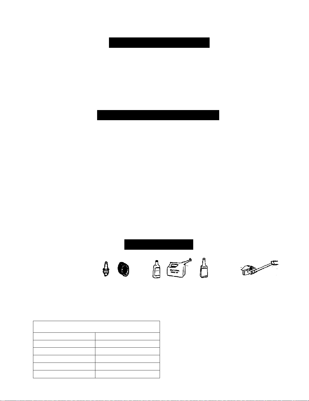
TABLE OF CONTENTS
Content
Warranty Information
Safe Operation Practices
Assembiy
Operation 8
Maintenance 12
Page
2
3
5
Content Page
Service & Adjustment
Off-Season Storage
Trouble-Shooting
Parts List
15
18
19
20
WARRANTY INFORMATION
One-Year Warranty on Craftsman Chipper-Shredder
For one year from the date of purchase, when this Craftsman chipper-shredder is maintained, lubricated, and
tuned up according to the operating and maintenance instructions in the operator’s manual. Sears will repair, free
of charge, any defect in material or workmanship.
This warranty excludes the blades, chipper blades, flails, air cleaners, spark plugs, catcher bags and tires which
are expendable parts and become worn during normal use.
If this chipper-shredder is used for commercial or rental purposes, this warranty applies for only 30 days from the
date of purchase.
WARRANTY SERVICE IS AVAILABLE BY CONTACTING THE NEAREST SEARS SERVICE CENTER IN THE
UNITED STATES. THIS WARRANTY APPLIES ONLY WHILE THIS PRODUCT IS IN USE IN THE UNITED
STATES.
This warranty gives you specific legal rights, and you may also have other rights which vary from state to.state,
Sears, Roebuck and Co., D/81 TWA, Hoffman Estates, IL 60179
ACCESSORIES
These accessories were
available when the chipper
shredder was purchased. They
are also available at most
Sears retail outlets, and service
centers. Most Seats stores can
order repair parts for you when
you provide the model number
of your chipper-shredder.
PRODUCT SPECIFICATION
Horsepower
Crankcase Capacity:
Fuei Tank Capacity: 4 Quart (UNLEADED)
Spark Piug Type
Spark Piug Gap .030"
Tire Pressure 24PSI
Spark Air
Plug Filter
40 oz. SAE 30 ENGINE OIL
Champion RC14YC
Engine Оггз
Oii Can
10H.P.
Stabilizer
Model Number........247..77.5890
Serial Number.........................................................
Date of Purchase
Record both serial number and date of purchase and
keep in a safe place for future reference.
...................................................
Tow Hitch Kit
.........................
Page 3

A
A
A
SAFE OPERATION PRACTICES
This symbol points out important safety instructions which, if not followed, could endanger the per
sonal safety and/or property of yourself and others. Read and follow all instructions in this manual before
attempting to operate your chipper shredder. Failure to comply with these instructions may result in per
sonal injury. When you see this symbol—heed its warning.
Your chipper-shredder was built to be operated according to the rules for safe operation in
DANGER- manual. As with any type of power equipment, carelessness or error on the part of the oper
' ator can result in serious injury. If you violate any of these rules, you may cause serious
injury to yourself or others.
WARNING: The Engine Exhaust from this product contains chemicals known to the State of California
to cause cancer, birth defects or other reproductive harm.
GENERAL OPERATION
• Read this owner's guide carefully In its entirety before
attempting to assemble this machine. Read,
understand, and follow all instructions on the machine
and in the manual(s) before operation. Be completely
familiar with the controls and the proper use of the
machine before operating It. Keep this manual in a safe
place for future and regular reference and for ordering
replacement parts.
• Your chipper-shredder is a powerful tool, not a
plaything. Therefore, exercise extreme caution at alt
times. Your unit has been designed to perform two
jobs; to chip and shred vegetation found in a normal
yard. Do not use it for any other purpose.
• Never allow children under age 16 to operate the unit.
Children 16 years and older should only operate the
unit under close parental supervision. Only responsible
individuals who are familiar with these rules of safe
operation should be allowed to use your unit.
• Keep the area of operation dear of all persons,
particularly small children and pets. Stop the engine
when they are in the vicinity of the unit. Keep work area
clean and dear of branches or obstacles which could
cause you to stumble or fall.
• When feeding material into this equipment, be
extremely careful that pieces of metal, rocks, bottles,
cans or other foreign objects are not included.
Personal injury or damage to the machine could result.
• Always wear safety glasses or safety goggles, during
operation and while performing an adjustment or
repdr, to protect eyes from foreign objects that may be
thrown from the machine.
• Wear sturdy, rough-soled work shoes and dose fittirtg
slacks and shirt Shirt and slacks that cover the arms
and legs and steel-toed shoes are recommended. Do
not wear loose fitting dothes or jewelry and secure hair
50 it is above shoulder length. They can be caught in
moving parts. Never operate a unit in bare feet,
sandals or sneakers. Wear gloves when feeding
material in the chipper chute or shredder hopper.
• Never place your hands, feet, or any part of your body
into the shredder hopper, chipper chute, discharge
opening, or near any moving part while the engine is
running. Keep dear of the discharge opening at all
times. If it becomes necessary to push material into the
chipper chute or shredder hopper, use a small
diameter stick, NOT YOUR HANDS.
If it is necessary for any reason to unclog the feed
intake or discharge openings or to inspect or repair any
part of the machine where a moving part can come in
contact with your body or clothing, stop the machine,
allow it to cool, disconnect the spark plug wire from the
spark plug and move it away from the spark plug
before attempting to unclog, inspect or repair.
Do not operate unit while under the influence of alcohol
or drugs.
The machine should only be operated on a level
surface. Never operate your unit on a slippery, wet,
muddy or icy surface. Keep your work area clean and
clear of branches or obstacles which could cause you
to stumble and fall. Do not overreach. Maintaining
proper footing and balance is essential to preventing
accidents.
Do not allow an accumulation cf proceed material to
build up in the discharge area as this will prevent
proper discharge and csm result in kick-back from the
chi];^er chute.
Keep your face and body back from chipper chute to
avoid accidental bounce back of any material.
Do not transport machine while engine is running.
If the cutting mechanism strikes a foreign object or if
your machine should start making an unusual noise or
vibration, immediately stop the engine and allow the
machine to come to a complete stop. Disconnect the
spark plug wire and move it away from the spark plug.
Take the following steps.
a. Inspect for damage.
b. Repair or replace any damaged parts.
c. Check for any loose parts and tighten to assure
continued safe operation.
Never attempt to attach or remove catcher bag when
engine is running. Shut the engine off and wait for the
impeller to come to a complete stop. The impeller
continues to rotate for a few seconds after the engine is
Page 4

shut off. Never place any part of the body in the
impeller area until you are sure the impeller has
stopped rotating.
Muffler and engine become hot and can cause a bum.
Do not touch.
Do not allow leaves or other debris to build-up on
engine’s muffler. The debris could ignite and cause a
fire.
Do not attempt to shred or chip material larger than
' specified in this manual. Personal injury or damage to
the machine could result.
Do not operate engine If air cleaner or cover over
carburetor air-intake is removed, except for
adjustment. Removal of such parts could create a fire
hazard.
Only use accessories approved for this machine by the
manufacturer. Read, understand, and follow all
instructions provided with the approved accessory.
If situations occur which are not covered by this
manual, use care and good judgment. Contact your
dealer for assistance.
Keep discharge chute deflector, chipper chute flap,
and all other guards and safety devices in place and
operating properly.
Only operate unit in good daylight. Do not operate unit
at night or in dark areas where your vision may be
impaired.
CHILDREN
Tragic accidents can occur if the operator is not alert to the
presence of small children. Children are often attracted to
the chipper-shredder and the chipping and shredding
activity. Never assume that children will remain where you
last saw them.
• Keep children out of the work area and under the
watchful eye of a responsible adult other than the
operator.
• Be alert and turn the unit off if a child enters the area.
• Never allow children underthe age of 16 to operate the
chipper-shredder.
SERVICE
• Use extreme care in handling gasoline and other fuels.
They are extremely flammable and the vapors are
explosive.
a. Store fuel and oil In approved containers, away
from heat and open flame, and out of the reach of
children. Check and add fuel before starting the
engine. Never remove geis cap or add fuel while
the engine is running. Allow engine to cool at
least two minutes before refueling.
b. Replace gasoline cap securely and wipe off an;
spilled gasoline before starting the engine as it
may cause a fire or explosion.
c. Extinguish all cigarettes, cigars, pipes and other
sources of ignition.
d. Never refuel unit indoors because flammable
vapors will accumulate in the area.
e. Never store the machine orfuei container inside
where there is an open flame or spark such as a _
gas hot water heater, space heater, clothes dryer
orftjrnace.
• Never run your machine in an enclosed area as the
exhaust from the engine contains carbon monoxide,
which is an odorless, tasteless and deadly poisonous
gas.
• To reduce fire hazard, keep engine and muffler free of
leaves, grass, and other debris build-up. Clean up fuel
and oil spillage. Allow unit to cool at least 5 minutes
before storing.
• Before cleaning, repairing, or inspecting, make certain
the impeller and all moving parts have stopped.
Disconnect the spark plug wire and keep wire away
from spark plug to prevent accidental starting. Do not
use flammable solutions to clean air filter.
• Check the blade and engine mounting screws at
frequent intervals for proper tightness. Also visually
inspect blades for wear and/or damage (e.g., bent,
cracked). Replace writh blades which meet original
equipment specifications.
• Keep all nuts, bolts, and screws tight to be sure the
equipment is in safe working condition.
• Never tamper with safety devices. Check their proper
operation regularly.
• After striking a foreign object, immediately stop the
engine, disconnect the spark plug wire from the spark
plug, and thoroughly inspect the unit for any damage.
Repair damage before starting and operating unit.
• Do not alter or tamper with the engine's governor
setting. The governor controls the maximum safe
operating speed of the engine.- Over-speeding the
engine is dangerous and will cause damage to the
engine and to other moving parts of the machine.
YOUR RESPONSIBILITY
Restrict the use of this power machine to
persons who read, understand and follow the
A
warnings and instructions in this manusil and on
the machine.
SAVE THESE INSTRUCTIONS FOR FUTURE REFERENCE
This unit is equipped with an internal combustion engine and should not be used on or near any unimproved forest-
covered, brush-covered or grass-covered land unless the engine’s exhaust system is equipped with a spark arrester
meeting applicable local or state laws (if any). If a spark arrester is used, it should be maintained in effective working
order by the operator.
In the State of Califomia the above is required by law (Section 4442 of №e California Public Resources Code). Other
states may have similar laws. Federal laws apply on federal lands. A spark arrester for the muffler is available through
your nearest Sears Authorized Service Center (See the REPAIR P/VtTS section of this manual.)
Page 5
ASSEMBLY
IMPORTANT: This unit is shipped without gasoiine
or oil in the engine. After assembly, see
OPERATION section of this manuai for proper fuel
and engine oil fill-up,
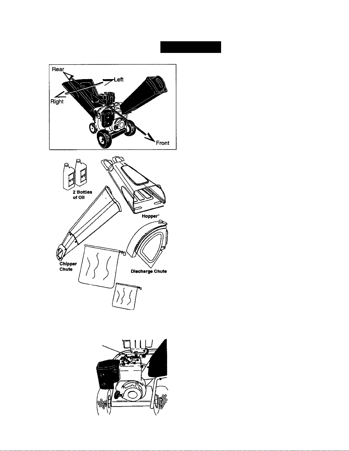
NOTE: To determine right and left hand sides of your
chipper-shredder, stand behind theunit with the
engine fardiest away from you. See Figure 1 inset.
Your chipper-shredder has been completely
assembled at the factory, except for the hopper
assembly, chipper chute, discharge chute and the
catcher bag. These parts are shipped loose in the
carton. A pair of safety glasses and two bottles of oil
are also included in the carton.
Remove From Carton
• Cut the comers of the carton. Remove all
packing inserts. Remove all loose parts
including owner’s manual. See Figure 1,
• Roll chipper-shredder out of the carton.
• Make certain all parts and literature have been
removed before the carton is discarded.
Leaf Bag
* The hoppar is packsd
in the top insert In
your chipper'Shrertder
carton.
Spark Plug Wire
Figure 1
Figure 2
Chip Bag
Loose Parts
(Refer to Figure 1.)
a. Hopper Assembly
b. Discharge Chute
c. Chipper Chute
d. Leaf Bag, chip bag
e. Bottle of Oil (2)
f. Safety Glasses (not shown in Figure 1}
g. Owner’s Manual (not shown in Figure 1)
Tools Required
1. 1 /2' or adjustable wrenches
2. 7/16" or adjustable wrenches ^
3. 9/16” or adjustable wrenches
4. Funnel
Disconnecting Spark Plug
• Disconnect the spark plug wire and move it
away from the spark plug before assembling the
chipper-shredder. See Rgure 2.
Attaching Discharge Chute
• Remove the wing knobs from each side of the
discharge opening on tine chipper-shredder.
• Using two 7/16" wrenches, remove hex lock nut,
two spacers, and the hex bolt from top of the
housing assembly. For easy assembly, do not
remove the second spacer from the hex bolt.
• Fierce the discharge chute in position on the
discharge opening as shown in step 1 in Figure
3. Insert hex bolt and ^acer through hinge on
discharge chute and housing (spacer fits inside
of hinge). See Figure 3 irtset A.
Page 6
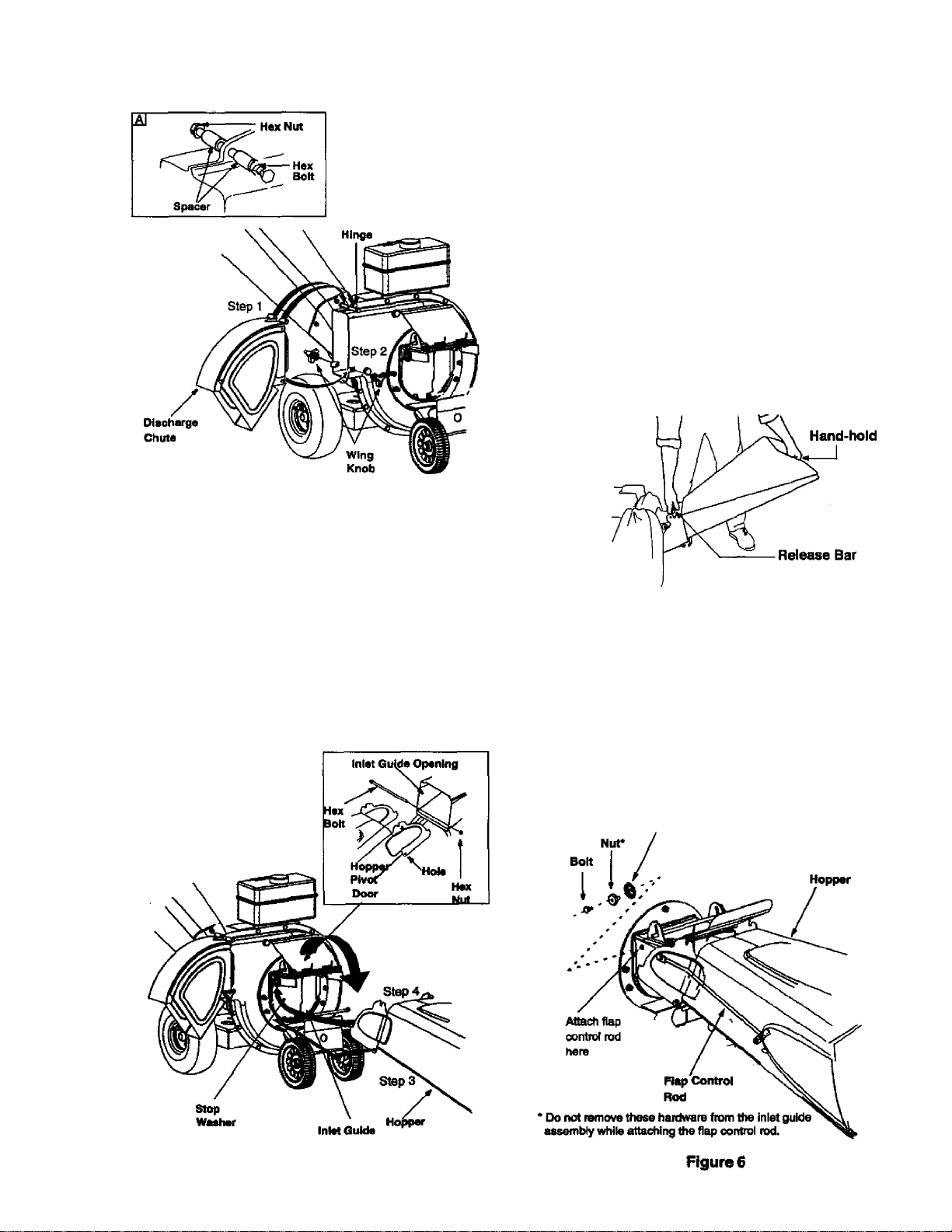
Figure 3
• Place second spacer over hex bolt inside the
other part of the hinge as shown in the inset.
Secure tightly with hex lock nut.
• Secure both sides of discharge chute to housing
using wing knobs that you earlier removed. This is
shown in step 2 in Figure 3. Tighten wing knobs.
Attaching Hopper Assembly
• Remove the 8-3/8” long hex bolt and the hex nut
from the bottom of the inlet guide opening. See
Figure 4 inset.
• Place the hopper assembly on the ground and
hold it in the position shown in Figure 4.
Holding the hopper, push hopper pivot door
down inside the hopper. See Figure 4.
Slide the hopper assembly towards the chipper
shredder housing so that the upper guide on the
hopper assembly slides under the stop washer
on each side of the inlet guide. See Figure 4.
Align the two holes (one on each side) of the
lower hopper with the two holes (one on each
side) of the inlet guide. See Figure 4 inset.
Insert the hex bolt (that you earlier removed)
from the left through the hole on the hopper ari3'
the inlet guide. Insert the hex nut onto the bolt
from the other side. See Figure 4 inset.
Tighten the bolt till the lock nut is engaged. Make
sure to remove sideplay from the bolt, but the
hopper should be able to pivot.
Figure 5
* To raise the hopper, hold the hopper by the
hand-hold and lift it up till it clicks into position.
See Figure 5.
• To iowerthe hopper, hold the hopper by the
hand-hold and pull the release bar. The hopper
should drop down. See Figure 5.
The flap control rod is already attached to the hopper
at the top. The other end of the rod has to be attached
to the stop washer on the inlet guide. See Figure 6.
stop .
Hex’ Washer
Figure 4
Page 7
Raise the hopper till it clicks into position.
Unscrew the shoulder bolt from the stop washer
on the inlet guide. See Figure 6.
Align the loose end of the flap control rod with
the stop washer on the inlet guide.
Slide the shoulder bolt through the opening In
the flap control rod. Secure tightly. See Figure 6.
WARNING: Hiis flap control rod is a safety
device to hold the flap in place inside the
A
hopper while shredding branches. Do not
operate the chipper-shredder without
properly attaching this flap control rod to the
unit
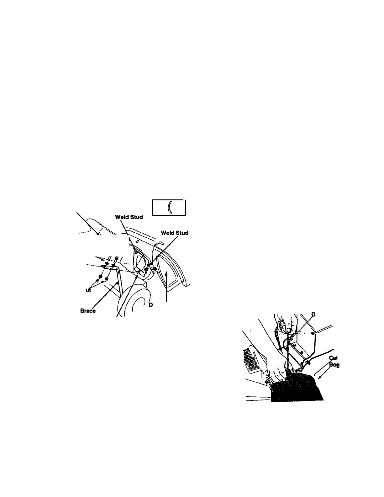
• Secure with the three paiirs of cupped washers
and hex nuts that you earlier removed. Do not
tighten the nuts at this time. Make sure to place
the cupped side of the washer against the
chipper chute.
• Align the holes towards the front opening of the
chute with the holes on the brace. See Figure 7.
• Insert one each of the hex bolts, lock nuts, and
flat washers (that you earlier removed) through
each hole in the chute and the brace. See
Figure 7 for the correct order. Tighten bolts." ^'
• Tighten bolts securing the brace to the frame.
• Tighten the three nuts on the weld studs.
Attaching Chipper Chute
• Your unit is shipped with one end of the brace
already secured to the lower frame. Loosen the
bolts securing the brace to the frame.
Chipper
Chute
L'FI$t3(\teher /
HexN
Weld Stud
Cupped
Washer -
ischarge Chute
Figure 7
Attaching Catcher Bag
Your chipper-shredder is equipped with two catcher
bags of different sizes (leaf bag and chip bag) to catch
the shredded material.Select the bag that is most
appropriate for the task ahead.
• To attach the bag, place the opening of the bag
over the chute deflector and the chute flange.
Make sure it completely covers the chute
deflector.
• Depress the plunger on the draw-string, and pull
on the draw-string until the bag is tight around
the chute opening. Release plunger to lock it into
position. See Figure 8.
NOTE: For easier handling, it is recommended that
a. the chip bag (which is smaller of the two)
should be used for catching chipped
branches.
b. the leaf bag (larger) should be used for
catching shredded leaves.
rawstring
Remove the three cupped washers and hex
nuts from the weld studs beside the opening on
the left side of the housing. See Figure 7.
Remove the two sets of hex bolt, lock nut, and
flat washer from the two holes on the upper end
of the brace. See Figure 7.
Place the chipper chute over the weld studs so
the slot on the chute is towards the bottom. Align
the three holes at the bottom of the chute with
the three weld studs.
tcher
Figure 8
Page 8
OPERATION
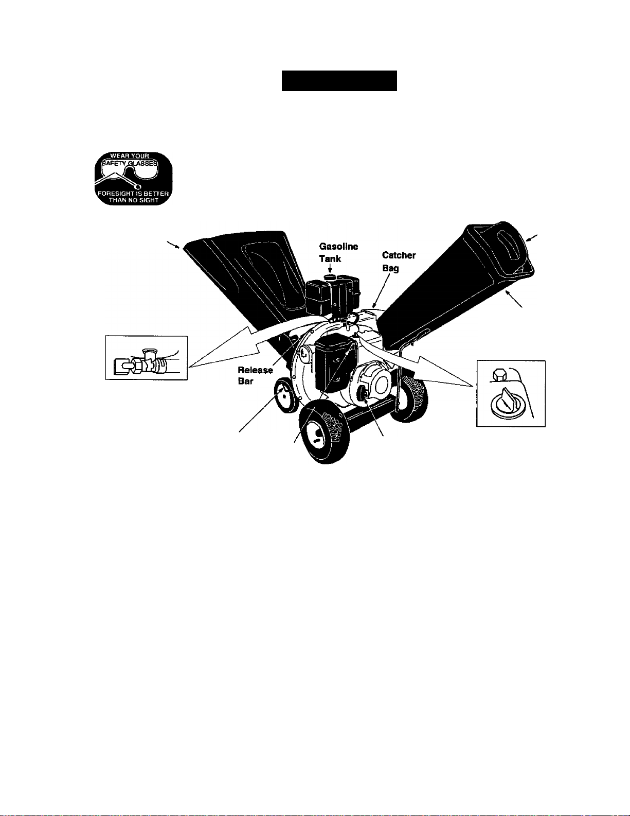
Read this owner's manual and safety rules before operating your chipper-shredder. Compare Figure 9 with
your chipper-shredder to familiarize yourself with the location of various controls and adjustments. Save this
manual for future reference.
The operation of any chipper-shredder can result in foreign objects being thrown into the
eyes, which can result in severe eye damage. Always wear safety glasses provided with
the chipper-shredder before chipping or shredding, or while performing-any adjustments
or repairs.
Hopper
Assembly.
Fuel Shut-Off Valve
Rear Wheel.
Lock Lever
Choke
Lever
Operating Controls
(Referto Figure 9.)
Release Bar
Used to release the hopper when raising or lowering.
Choke Lever
Used to enrich the fuel mixture in the carburetor
when starting a cold engine.
Starter Handle
Used to manually start the engine.
Hopper Assembly
Allows leaves and small branches upto VZ' diameter
to be fed into the impeller for shredding. Lower the
hopper to collect raked material for shredding.
Stop Switch
Used to stop the engine; sUso has to bo turned on
before pulling the starter handle to start the engine.
Chipper
Chute
Starter
Handle
Figure 9
Chipper Chute
Allows bulky vegetation like stalks or heavy branches
upto 3” diameter to be fed into the impeller for
chipping. The .tamper helps to feed smaller material
into the chipper chute. " ' ■ " *
Catcher Bags
A large leaf bag and a smaller chip bag used to
collect the shredded material.
Rear Wheel Lock Lever
Used to lock the rear wheels from moving.
Fuei Shut-off Valve
Used to turn on or off the flow of gasoline to the
engine. Turn the valve ON to start the engine.
Stop Switch
Stopping Engine
• Turn the stop switch to OFF. Disconnect the
spark plug wire and move it away from the spark
plug to prevent accidental starting.
Tamper
Meets ANSI Safety Standards
Sears chipper-diredders conform to safety standsffd B 71.6 -1990 of tiie Americai National Standards Institute (ANSI).
8
Page 9
Lowering Hopper Assembly
In order to rake leaves into the hopper, you will need
to lower the hopper.
• To lower the hopper assembly, use one hand to
grasp the hand-hold at the top of the hopper
assembly and lift slightly. See Figure 5.
• Pull up on the release bar, and lower the hopper
assembly to the drop-down position. Release
' the bar. See Figure 5.
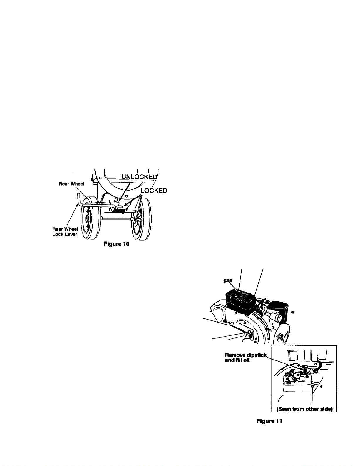
Using Rear Wheel Lock Lever
Keep the rear wheels locked while operating the unit.
Unlock the rear wheels for transporting the unit.
• Pull the lever out and down and insert in bottom
slot to lock the rear wheels.
• Pull the lever out and upwards and insert in top
slot to unlock the wheels. See Figure 10.
Gas And Oil Fill-Up
Oil (2 bottles shipped with unit)
• Only use high quality detergent oil rated with
API service classification SF, SG or SH. Select
the oil's viscosity grade according to your
expected operating temperature. Follow the
chart below.
Colder
32®F
Warmer
Add oil, if necessary, to bring the oil level to
FULL mark on the dipstick.
• Replace dipstick and tighten.
NOTE: Do not overfill. Oil bottles packed with unit
contain a total of approximately 40 oz. of oil.
Gasoline
WARNING: Experience indicates that alcohol
blended fuels (called gasohol or using ethanol or
metiianol) can attract moisture which leads to
separation and fonnation of acids during storage.
Acidic gas can damage the fuel system of an engine
while in storage. To avoid engine problems, the fuel
system should be emptied before storage for 30
days or longer. Drain the gas tank, start the engine
and let it run until the fuel lines and carburetor are
empty. Use fresh fuel next season. See STORAGE
instructions for additional information. Never use
engine or carburetor cleaner products in the fuel tank
or permanent damage may occur.
Fill gasoline tank as follows.
• Remove fuel cap.
• Make sure the container (from which you will
pour the gasoline) is clean and free from rust or
foreign particles. Never use gasoline that may
be stale from long periods of storage in the
container.
• Fiii fuel tank with clean, fresh, lead-free
automotive gasoline. DO NOT use Ethyl or high
octane gasoline. See Figure 11. Replace fuel
cap.
Remove cap
and fill
5W30
SAE30
NOTE: AJthough multi-viscosity oils (5W30,10W30,
etc.) improve darting in cold weather, these
multiviscosity oils mil result in increased oil
consumption when used above 40* *’F. Check the dl
level more frequently to avoid possS^e engine
damage from running low on oil.
Fill engine with oil as follows.
• Remove oil fill dipstick. See Figure 11.
• With chipper-^redderon level ground, use a funnel
to fill engine wHh oil to FULL mark on dipstick.
Capacity is af^roximately 40 ounces. Be careful not
to overfill. Replaoe dipstick and lights.
• Start and run engine for 30 seconds. Shut
engine off. Wait 30 seconds and dieck oil level.
Page 10

WARNING: Do not fill closer than 1/2
A
• Check the fuel level periodically to avoid running
• If the unit runs out of gas as it is shredding or
inch from the top of the fuel tank to prevent
spills and to allow for fuel expansion. If
gasoline is accidently spilled, move chipper
shredder away from area of spill. Avoid
creating any source of ignition until gasoline
vapors have disappeared.
out of gasoline while operating the chipper
shredder.
chipping, it may be necessary to unclog the unit
before it can be restarted. Refer to Removing
the Flail Screen in SERVICE AND
ADJUSTMENT section.
Starting Engine
WARNING: Be sure no one other than
A
This engine conforms to the low emissions standard
and is designed for maximum performance and life if
operated with the choke fully open in RUN position.
4. Move choke
the operator is standing near the chipper
shredder while starting or operating. Do not
operate this chipper-shredder unless the
chute deflector has been properly installed
and is secured with the hand knobs.
1. Attach spark
plug wire
to CH
2. Turn fuel valve
to “ON”
before proceeding with starting procedure.
• Move stop switch to ON position. See Figure 12.
• Move choke control to CHOKE position. See
Figure 12. If restarting a warm engine after a
short shutdown, move choke lever to RUN
position.
• Grasp starter handle and pull rope out slowly
until engine reaches start of compression cycle
(rope will pull slightly harder.attbis point). Let the
rope rewind slowly. See Figure 12.
• Pull rope with a rapid full arm stroke. Let rope ^'
return to starter slowly.
• When engine starts, let the engine warm up for
several seconds to several minutes depending
on the temperature. Then move choke lever
towards RUN position until engine runs
smoothly.
• Moving the choke gradually towards RUN allows
the engine to accept small changes in speed
and load until the choke is fully open at RUN
position.
• Move choke lever to RUN position as engine
warms up.
• If engine fails to start after three pulls, move
choke lever to RUN position and pull starter rope
again.
• If engine fires, but does not continue to run,
move choke lever to Choke position and pull
rope again.
NOTE: A noise will be heard when finding the start of
the compression cycle. This noise is caused by the
flails and fingers h^/c/j are part of the shredding
mechanism falling into place, and should be
erqjected. In addition, the flails and fingers will be
noisy after the engine is started, until file impeller
reaches full speed.
Figure 12
NOTE; To prevent the unit from sliding, place your
foot firmly against fite tire.
• Attach spark plug wire and rubber boot to spark
plug. See Figure 12.
• Always tu m fuel shut-off valve to ON position
•
Stopping Engine
• Move stop switch to OFF ‘0osifii)n.
• Turn fuel shut-off valve to OFF position.
• Disconnect spark plug wire and move away from
spark plug to prevent accidental starting.
WARNING: Do not move choke control to
A
CHOKE position to stop the engine. Serious
engine damage may occur.
Using Your Chipper-Shredder
WARNING: Do not attempt to shred or
A
10
chip any material other than vegetation
found in a normal yard (i.e., branches,
leaves, twigs, etc.}.
The chipper-shredder is designed for two
different methods of operation,
a. Leaves and small branches up to 1 /2”
diarrieter (maximum) can be fed into the
Page 11

hopper assembly when it is in the raised or
lowered position. See Figure 13.
b. Bulky material, such as stalks or heavy
branches, up to 3” in diameter should be
fed into the chipper chute. See Figure 13.
WARNING: Do not put material larger
dk
A
For best performance, it is important to keep the
shredding blade and the chipper blades sharp. If the
composition of the material being discharged
than is specified into the hopper, and/or into
the chipper chute. Personal injury or
damage to the machine could result.
if it becomes necessary to push material into the
chipper-shredder, use the tamper— not your
hands.
For collecting raked leaves into the hopper, first
remember to put the hopper flaps behind the
retaining bracket inside the upper hopper.
WARNING: Never remove chute deflector
till the unit has completely stopped. Never
shut off the engine until all chipping is
completed.
changes (becomes stringy, etc.) or if the rate at which
the material is discharged slows down considerably, it
is likely that the shredding blade and/or chipper
blades are dull and need to be sharpened or
replaced. Refer to Service and Adjustments section
on page 15 of this manual.
IMPORTANT: There is a flail screen located inside
the housing in the discharge area. If the flail screen
becomes clogged, remove and clean as instructed in
the Service and Adjustments section.
WARNING: The chipper-shredder
discharges materials with considerable
A
velocity. Keep away from the area around the
discharge chute. Make sure that the rubber
flaps inside the hopper are not tucked under
the bracket while operating the shredder.
Always stop the engine and disconnect the
spark plug wire wrfien removing or attaching
the bag, changing containers, or removing the
shredded material. Wear safety glasses and
gloves whenever using the chipper-shredder.
Lower the hopper to collect
raked material for shredding
* Um leaf bag for ahraddod ioavaa and chip bag for chipped branches
Shred material upto 1/2 inch In diameter
Catch shredded material
Chip material upto
3 inches In diameter
Figure 13
11
Page 12

MAINTENANCE
General Recommendations
• Always observe safety rules when performing
any maintenance.
• The warranty on this chipper shredder does not
cover items that have been subjected to operator
' abuse or negl igence. To receive full value from
the warranty, operator must maintain the chipper
shredder as instructed in this manual.
• Some adjustments will need to be made
periodically to maintain your unit properly.
• All adjustments in the Service and Adjustments
section of this manual should be checked at least
once each season.
• Follow the maintenance schedule given below.
• Periodically check all fasteners and make sure
these are tight.
WARNING: Always stop the engine and
dk
disconnect the spark plug wire before
performing any maintenance or adjustments.
Never remove discharge chute till the
engine has completely stopped.
Cleaning
• Clean the chipper-shredder by running water
from a hose through the hopper assembly and
chipper chute with the engine running. Allow the
chipper-shredder to dry thoroughly.
• Wash the bag periodically with water. Allow to dry
thoroughly in the shade. Do not use heat.
Engine Maintenance
Engine Oil
• Only use high quality detergent oil rated with API
service classification SF, SG or SH. Select the
oil’s viscosity grade according to your expected
operating temperature. Referto page 9 of this
manual for viscosity chart.
• The four-cycle engine of your chipper-shredder
will normally consume some oil. Therefore, check
engine oil level regularly approximately every five
hours of operation and before each usage.
• Stop engine and wait severai minutes before
checking oil level. With engine on level ground,
Customer Responsibilities
MAINTENANCE
SCHEDULE
H
Oil pivot points
o
3
a
o
cc
Clean shredder
0.
Check engine oil
Change engine oil
UJ
z
Service air cleeiner
o
lU
Clean engine
I S
•f
SERVICE
/
/
DATES
■ -
7
Check spark plug
Clean muffler
^ Check and service if necessary
7
12
Page 13

the oi! must be to FULL mark on dipstick.
• Change engine oil every 50 hours of operation
under normal operating conditions. Change oil
every 25 hours when operating nder heavy
load or in high temperatures.
To Drain Oil
Drain oil while engine is warm. Follow instructions
given below.
• Remove oil drain plug. Catch oil in a suitable
container.
• When engine is drained of all oil, replace drain
plug securely.
• Refill with fresh oil. Refer to GAS AND OIL
FILL-UP section on page 9.
• Replace dipstick.
Air Cleaner
The air cleaner prevents damaging dirt, dust, etc.,
from entering the carburetor and being forced into
the engine and is important to engine life and
performance. For location of air cleaner, see Figure
14 inset.
To Service Air Cleaner:
Service air cleaner cartridge every 25 hours of
operation or every season, whichever comes earlier.
Service more often if you operate the chipper
shredder under extremely dusty conditions.
• Remove two hex screws and cover holding the
air cleaner cartridge in place. Remove air
cleaner assembly from inside the cover and
disassemble. See Figure 14.
• Wash pre-cleaner, if so equipped, in liquid
detergent and water. Squeeze dry with a clean
cloth. Saturate in engine oil, then squeeze in
clean, absorbent cloth to remove all of the
excess oil. Replace the pre-cleaner if it is very
dirty or damaged,
• To service cartridge, clean by tapping gently on
a flat surface. Do not use any oil, petroleum
solvents like kerosene, or pressurized air to
clean cartridge. Replace if the cartridge is very
dirty or damaged.
• Reassemble first the retainer on pre-cleaner
and cartridge and then the cartridge assembly
inside the cover. Insert tabs on cover into slots
in base and tighten the two screws earlier
removed.
Clean Engine
• Clean engine periodically. Remove dirt and
debris with a cloth or brush.
• Frequently remove grass clippings, dirt and
debris from cooling fins, air intake screen and
levers and linkage. This will help ensure
adequate cooling and correct engine speed.
See Figure 15.
Clean here
QJpan here
Figure 15
• Yearly or every 25 hours, whichever occurs
first, remove the blower housing and clean the
areas shown in Figure 15 to avoid
overspeeding, overheating and engine
damage. Clean more often if necessary.
NOTE: Cleaning wfi/ï a forceful spray of water is not
recommended as water could contaminate the fuel
system.
• Remove combustion deposits every 100 hours
of operation. Remove the cylinder head, scrape
and wire brush such deposits from cylinder
13
Page 14

head, top of piston and around valves. Use a
soft brush to remove the deposits.
Reassemble gasket and cylinder head. Turn
screws down finger-tight. Torque cylinder head
screws in a staggered sequence to 165 in.-lbs.
WARNING; Temperature of muffler and
A
nearby areas may exceed 150° F(65°C).
Avoid these areas.
Inspect periodically, and replace if necessary. If
your engine is equipped with a spark arrester
screen assembly, remove every 50 hours for
cleaning and inspection. Replace if damaged.
WARNING: Always stop engine,
A
disconnect spark plug wire, and move it
away from spark plug before performing any
adjustments or repairs.^
Spark Plug
• Clean the spark plug and reset the gap to .030”
at least once a season or every 50 hours of
operation. See Figure 16. Sparkplug
replacement is recommended at the start of
each season. Refer to engine parts list for
correct spark plug type.
NOTE: Do not sandblast ^arkplug. Sparkplug
should be cleaned by scrying or wire brushing and
washing witii a commercial solvent.
Muffler
WARNING: Do not operate the chipper
A
shredder without a muffler, or tamper with
the exhaust system. Damaged mufflers or
spark arresters could create a fire hazard.
Lubrication
Lubricate the pivot points on the release bar, hopper
assembly, chute deflector and chipper chute once a
season using a light oil. See Figure 17.
Figure 17
14
Page 15

SERVICE & ADJUSTMENTS
Removing Flail Screen
If the discharge area becomes clogged, remove the
flail screen and clean area as follows.
• Stop engine, m£ike certain the chipper
shredder has come to a complete stop and
disconnect spark plug wire from the spark plug
before unclogging the chute.
• Remove the two hand knobs on each side of
the discharge chute (also called the chute
deflector).
• Lift the discharge chute up, and keep it out of
the way.
• Remove two hex bolts which extend through
the housing. See Figure 18.
• Pull the flail screen from inside the housing.
See Figure 18.
• Clean the screen by scraping or washing with
water.
• Reinstall the screen.
• Put the discharge chute back to its original
position and tighten the hand knobs.
NOTE: Be certain to reassemble the flail screen with
the curved side down.
by removing three pairs of hex nut and cupped
washer.
Holding the chute to the frame, remove the hex
bolts that secure the brace to the frame. Remove
the brace. You will need a 7/16” wrench for this.
Rotate the impeller assembly by hand until you
locate one of the two chipper blades in the chipgec..
chute opening. Remove the blade, using a 3/1
alien wrench on the outside of the blade and 1/2”
wrench on ttie impeller assembly (inside the
housing). See Figure 19.
Slot
Blade
Chute Deflector
Sharpening Or Replacing Blades
Chipper Blades
• Disconnect spark plug wire and move it away
from spark plug.
• Remove the flail screen as Instructed.
• Using a 1^” wrench, remove the clipper chute
Sharp Edge
Figure 19
• Remove the other blade jrvthe ^ame manner.
• Replace or sharpen blades.
• If sharpening, make certain to remove an equal
amount from each blade.
• Reassemble in reverse order. Make certain
blades are reassembled with the sharp edge
facing the direction shown in Figure 19 (sharp
edge is assembled toward the slotted opening at
the bottom).
• Torque bolts and nuts to 250-300 inch-pounds.
Shredding Blade
The shredding blade may be removed for sharpening
or replacement as follows.
• Disconnect spark plug wire and move it away
from spark plug.
• Lower the hopper assembly. Block up the
housing. See Figure 20.
15
Page 16

Weld Bolt
Figure 20
When reassembling the blade, tighten center
bolt to between 550-700 inch-pounds and the
two outer bolts to 250-300 inch-pounds, or
lacking torque wrench, tighten securely.
Figure 21
• Remove the six hex lock nuts and lock washers
from the housing weld bolts using a 1 /2” wrench.
Separate the chipper-shredder into two halves.
• Remove the back-up plate.
NOTE: When reassembling, make certain the
embossed tab faces inward towards the impeller, and
opening on the back-up plate is toward die bottom of
the unit.
• Remove the two hand knobs and cupped
washers which secure the chute deflector. Raise
the chute deflector.
• Insert a 1 /2" or 3/4" diameter pipe through the
flail screen into the impeller to keep it from
turning, or remove the flail screen and insert a
piece of wood (2 x 4) into the chute opening.
• Remove the two outside screws on №e blade,
using a 3/16” alien wrench and a 1^” wrench.
• Remove the blade by removing the center bolt,
lock washer and flat washer.
WARNING: Use caution when removing
A
the blade to avoid contacting the weld bolts
on tite housing.
Adjusting Carburetor
WARNING: If any adjustments are made to
A
Differences in fuel, temperature, altitude or load may
require minor adjustments to the carburetor. This
carburetor is equipped with an idie mixture valve with
a limiter and an idle speed adjustment screw.
* Start engine and let it run for about 5 minutes.
• Rotate carburetor throttle lever against the idle
the engine while the engine is running (e.g.
carburetor), keep clear of all moving parts.
Be careful of heated surfeoes and muffler.
speed screw and hold it. Turn idle speed screw
to obtain 1750 rpm. See Figure 22.
When sharpening the blade, follow the original
angle of grind as a guide. It is extremely
important that each cutting edge receives an
equal amount of grinding to prevent an
unbalanced blade.
An unbalanced blade will cause excessive
vibration when rotating at high speeds and may
cause damage to the unit The blade can be tested
for balance by balsuxxng it on a round shaft
screwdriver or nail. Remove metal from the heavy
side until it is bdanced evenly. See Rgure 21.
Rotate idle mixture valve full bavel clockwise
and then counter-clockwise. Rnally position idle
mixture valve in middle of travel. See Figure 22.
16
Page 17

Check idle speed and re-adjust to 1750 rpm, if
necessary.
Engine should accelerate smoothly. If it does
not, adjust idle mixture valve counter-clockwise
1/8 turn.
WARNING: Air cleaner and its cover must
A
be assembled to the carburetor before
starting the engine.
Adjusting Engine Speed
The engine speed on your chipper-shredder has
been set at the factory. Do not attempt to increase
engine speed or it may result in personal injury. If you
believe the engine is running too fast or too slow, take
your chipper-shredder to the nearest SEARS service
center for repair and adjustment.
Tires
Recommended operating tire pressure is 24 p.s.i.
(sidewall of tire may give tire manufacturer's
recommended pressure). Equal tire pressure should
be maintained on both tires.
WARNING: Excessive ptessure when seating
A
beads may cause tire/rim assembly to burst writh
force sufficient to cause serious injury.
Replacing Fuel Filter
• Drain the gasoline tank by running the engine till
it runs out of gasoline.
• Using a set of pliers, squeeze and unclamp the fuel
line hose. Remove the old filter. See Rgure 23.
• Replace with a new filter and reclamp.
17
Page 18

STORAGE
Prepare your chipper-shredder for storage at the end
of the seeison or if the unit will not be used for 30 days
or more.
WARNING: Never store machine with fuel
A
A yearly check-up by your local Sears service center
is a good way to make certain your chipper-shredder
will provide maximum performance for the next
season.
in the fuel tank inside of building where
fumes may reach an open flame or spark,
or where ignition sources are present such
as hot water and space heaters, furnaces,
clothes dryers, stoves, electric motors, etc.
Chipper-Shredder
• Clean the chipper-shredder thoroughly.
• Wipe unit with an oiled rag to prevent rust (use a
light oil or silicone).
Engine
IMPORTANT: It is important to prevent gum deposits
from forming in essential fuel system parts such as
carburetor, fuel filter, fuel hose, or tank during
storage. Also, experience indicates that alcohol
blended fuels (called gasohol or using ethanol or
methanol) can attract moisture which leads to
separation and formation of acids during storage.
Acidic gas can damage the fuel system of an engine
while in storage.
Drain the fuel tank.
Start the engine and let it run until the fuel lines
and carburetor are empty.
Drain carburetor.
Never use engine or carburetor cleaner
products in the fuel tank or permanent damage
may occur.
Use fresh fuel next season.
NOTE: Fuel stabilizer is an acceptable alternative in
minimizing the formation of fuei gum deposits during
storage.
Add stabilizer to gasoline in fuel tank or storage
container.
Always follow the mix ratio found on stabilizer '
container.
Run engine at least 10 minutes after adding
stabilizer to allow the stabilizer to reach the
carburetor.
Do not drain the gas tank and carburetor if using
fuel stabilizer. Drain all the oil from the
crankcase (this should be done after the engine
has been operated and is still warm) and refill
the crankcase with fresh oil.
If you have drained the fuel tank, protect the
inside of the engine as follows.
Remove spark plug, pour approximately 1/2
ounce (approximately one tablespoon) of engine
oil into cylinder and crank slowly to distribute oil.
Replace spark plug.
Other
• Do not store gasoline from one season to
another.
• Replace your gasoline can if your can starts to
rust. Rust and/or dirt in your gasoline will cause
problems. Store unit in a clean, dry area. Do not
store next to corrosive materials, such as
fertilizer.
NOTE: If storing in an unventiiated or metal storage
shed, be certain to rustproof the equipment by coating
with a light oil or silicone.
1
18
■
Page 19

TROUBLE-SHOOTING
Problem
Engine fails to start
Loss of power; operation erratic
Engine overheats
Too much vibration
Unit does not discharge
Rate of discharge slows
considerably or composition of
discharged material changes
Possible Cause
1. Fuel tank empty, or stale fuel
2. Spark plug wire disconnected
3. Faulty spark plug
4. Fuel shut-off valve not turned ON.
1. Spark plug wire loose
2. Unit running on Choke
3. Blocked fuel line or stale fuel
4. Water or dirt in fuel system
5. Carburetor out of adjustment
6. Dirty air cleaner
1. Carburetor not adjusted properly
2. Engine oil level low
1. Loose parts or damaged impeller
1. Discharge chute clogged
2. Foreign object lodged in impeller
1. Shredding blade and/or chipping
blade dull
Corrective Action
1. Fill tank with clean, fresh fuel
2. Connect wire to spark plug.
3. Clean, adjustgap or replace.
4. Move valve to ON position
1. Connect and tighten spark plug '
wire
2. Move choke lever to OFF position
3. Clean fuel line; fill tank with clean,
fresh gasoline.
4. Disconnect fuel line at carburetorto
drain fuel tank. Refill with fresh fuel.
5. Contact your SEARS service
center.
6. Sen/ice air cleaner.
1. Contact your SEARS service
center
2. Fill crankcase with proper oil
1. Stop engine immediately and
disconnect spark plug wire.
Tighten all bolts and nuts. Make
all necessary repairs. If vibration
continues, have unit serviced by a
SEARS service center.
1. Stop engine immediately and
disconnect spark plug wire, clean
flail screen and inside of blower
housing.
2. Stop engine immediately and
disconnect spark plug wire.
Remove lodged object.
1. Sharpen or replace blade(s)
, , . —- -
For repairs beyond the minor adjusbnents listed above, please contact your nearest SEARS service center.
19
Page 20

PARTS LIST
CRAFTSMAN 10 H.P. CHIPPER SHREDDER MODEL 247.775890
20
Page 21

CRAFTSMAN 10 H.P. CHIPPER SHREDDER MODEL 247.775890
Key
No.
1
2
3
4
5
6'
7
8
9
10
11
12
13
14
15
16
17
18
19
20
21
22
23
24
25
26
27
28
29
30
31
32
33
34
35
36
37
38
39
40
41
42
44
_
Part No.
770-0819A
11480
681-0118
710-0542
710-0607
710-3256
712-0429
711-1304 /Vxle Shaft
712-3027
714-0104
726-0106
732-0306
732-0546
732-0629
734-1797
736-0160
736-0117
736-0119
726-0299 Push Cap
747-0531A
747-0747
747-0982
781-0492A
781-07540689
781-07550689
781-0698
781-0715
726-0214
734-1845
736-0366
738-0813
681-0048
681-00940689
710-0382
712-0384
781-0457
681-0004A0689
681-01170689
710-0157
710-3180
710-0825
710-3008
712-3004A
726-0211
Description
Owner’s Manual
Stop Washer
Inlet Guide Assembly
Hex Washer Hd. Screw 5/16-18 x 8.38’
TL Hex Screw 5/16-18 x 0.5"
Button Head Screw
Hex Lock Nut 5/16-18
Hex Lock Flanged Nut 1/4-20
Internal Cotter Pin
Cap Nut
Compression Spring
Torsion Spring
Hopper Door Spring
Complete Wheel: Grey
Flat Washer
Flat Washer
Lock Washer
Rod: 5/16 Dia.
Hopper Door Rod
Lock Rod
Hopper Door Pivot
Upper Hopper: Polo Green
Lower Hopper: Polo Green
Hopper Lock Bracket
Shredder Plate
Push Cap
Complete Wheel Grey
Flat Washer 5/81.D.
Shredder Axle
Knob Assembly
Discharge Chute Assembly: Polo Green
Hex Bolt 1/2-13 XS’Gr. 5
Hex Center Lock Nut 1^-13
Shredder Screen
Outer Flail Housing Assembly
Inner Flail Housing Assembly
Hex Bolt 5/16-24 X 0.75" Gr. 5
Hex Bolt 5/16-18 X 1.75" Gr. 5
Hex Screw 1/4-20 X 3.75"
Hex Bolt 5/16-18X0.75*
Hex Lock Flange Nut 5/16-18 Gr. 5
UNut 5/16-18
Key
No.
45
46
47
48
49
50
51
52
53
54
55
57
58
59
60
61
62
63
64
65
66
67
68
69
70
71
72
73
74
75
76
83
84
85
86
87 735-0651
88
90
91
92 781-0752
94
95
96
97
98 ,
99
100
Part No.
747-1124
736-0170
750-0793
781-0459B
194G4321182-El
736-0242
726-0201
681-0068
710-0106
710-0751
712-3010
728-0175
731-1899
735-0249
736-0173
715-0129 Spiral Pin
749-1024
781-0633
719-0329
781-0735
715-0166
711-0833B Clevis Pin
681-0146
742-0571
710-1054
681-0144
712-0411
742-0653
710-1254
736-0217
736-0247
731-1617
764-0501 Chip Bag
764-0502
735-0127
751B094095
747-1125
738-0946 ‘
726-0135
751B493342
751-0535
726-0205
781-0497
781-0498
738-0137A
J____
Description
Flap Control Rod
Bell Washer
Hinge Spacer: Chute
Shredder Frame
Engine
Belleville Washer - ~
Speed Nut
Chipper Chute Assembly: Weldment ' “ ■
Hex Bolt 1/4-20 x 1.25’ Gr. 5
Hex Bolt 1/4-20 X .625
Hex Nut 5/16-18
Rivet
Chipper Chute
Chute Flap
Flat Washer
Chute Support
Chute Flap Strip
Flail Blade
Retaining Clip
Spring Roll Pin
Impeller Assembly
Shredder Blade
Flat Hd. Sor. 5/16-24X.75"
Arm Bracket /tesembly
Hex Top Lock Nut
Chipper Blade
Hex Patch Bolt 3/8-24 X 2.25” Gr. 8
Lock Washer
Flat Washer
Tamper Plug
Leaf Bag
Rubber Washer
Rubber Flap
Screw (included in #95 assembly)
Flap Retaining Bail
Shoulder Scraw; - * .
Hopper Flap Mounting Bracket
Speed Cap Nut
Fuel tank
Fuel Line Hcse
Hose Clamp
Mounting Bracket
Support Bracket
Shoulder Screw
21
Page 22

CRAFTSMAN 10 H.P. ENGINE MODEL NO. 19G432-1182-El FOR CHIPPER SHREDDER
MODEL NO. 247.775890
Key
No. Part No.
495631
1
495657
2
3 *391086
214347
5
0*272163
7
498038
8
9 0*27803
10
11
13
14 94622
15 94239
306
307
308
337
383
552 491986
635
869
871
978
979
982
1019 495861
1058 273682
94621
280819
94565
496797
94930
225055
496018
89838
66538
211661
261961
*271736
494807
94658
Description
Cylinder Assembly
Bushing
Seal-Oil
Head-Cylinder
Gasket-Cylinder Head
Breather Assembly
Gasket-Brealher
Screw-Breather Mtg.
Tube-Breather
Screw-Cylinder Head
(3 9/16” Long)
Screw-Cylinder Head
(3" Long)
Plug-Oil
Shield-Cylinder
Screw-Hex.
Cover-Cylinder
Plug-Spark (Resistor Type)
Wrench-Spark Plug
Bushing-Governor Crank
Elbow-Spark Plug
Seat-Valve
Guide-Exhaust Valve
Note: 231218 Guide-Intake Valve
Gasket-Oil Guard Cover
Cover—Oil Gard®
Screw—Hex.
Label Kit
Owner’s Manual
383
10
337
14 13
'A' REQUIRES SPECIAL TOOLS
TO INSTALL. SEE REPAIR
INSTRUCTION MANUAL.
Key
No. Part No. Description
280819
11
495659 Washer Set
75
493280
98
159 281358
161
163
165
222 499106
258 94929
307
354
359
445
467 280715 Knob
507 398525
520
535 492889
642 281357
969 94777
497669
0*272706
92791
496077 RIter-Air
Included in Casket Set-Part No. 497070.
*
Included in Valve Overhaul Gasket Set-Part No. 498534.
0
Tube-Breather
Screw-idle Speed
Support-Air Cleaner
Beise-Air Cleaner
Gasket-Air Cleaner
94692 Nut-Wing
94930
90576
Bracket-Control
Screw-Hex.
Screw-Hex.
Nut-Hex.
Washer-Lock
Insulator
93722 Terminal
RIter-Air
Cover-Air Cleaner
Screw^lotted Hex.
1019 LABEL KIT 1058 OWNER’S MANUAL
Page 23

CRAFTSMAN 10 H.P. ENGINE MODEL NO. 19G432-1182-El FOR CHIPPER SHREDDER
MODEL NO. 247.775890
Key
Part No.
No.
*271701
12
*27876
*27877
15A
16
T7
18
19
20
21
22
24
25
26
27
28
29'
30 222113
32
33
34
35
40
45
46
146
219
220
230
244
411
524
614
616
741 263025
866
★
91488
495866
29530
496981
295964
*391086
281658
222698
4ЭЭ907
499908
499909
499910
499721
299743
391670
391671
391672
263181
4ЭЭ911
499920
390401
390773
263017
261055
221596
260933
214786
497037
221551
230318
281370
496818
497656
Included in Gasket Set-Part No. 497070.
Gasket-Crankcase (.015" Thick, Std.)
Gasket-Crankcase (.005" Thick)
Gasket-Crankcase (.009" Thick)
Plug-Oil
Crankshaft
Bearing-Ball
Cover-Crankcase
Bushing
Seal-Oil
Cap-Oil Fill
93585
94690
Screw-Hex.
Screw-Hex. (In Position #1)
Key-Flywheel
Piston Assy. (Standard)
Piston Assy. (.010” O.S.)
Piston Assy. (.020” O.S.)
Piston Assy. (.030” O.S.)
Ring Set (Standard)
Ring Set (Std. Chrome)
Ring Set (.010” O.S.)
Ring Set (.020” O.S.)
Ring Set (.030” O.S.)
Lock-Piston Pin
Pin-Piston (Std.)
Pin-Piston (.005" O.S.)
Rod-Connecting (Standard)
Rod-Connecting (.020" U.S.)
Dipper-Connecting Rod
Screw-Connecting Rod
94670
Valve-Exhaust
Valve-Intake
Spring-Valve
65906
Retainer-Spring
Tappet-Valve
Gear-Cam
Key-Timing
94388
Gear-Governor
Washer-Thrust
Washer-Gov. Crank
94927
94802 Plug
Connector—Hose
Seal-Fill Plug
Pin-Cotter
93306
Crank-Govemor
Gear-Timing
1 Seal-Valve
Description
302
Q 9
33
34
35 Щ 35Щ
40^ 868#)
45
c2)
24^
TO INSTALL. SEE REPAIR
INSTRUCTION MANUAL.
40^
Key
Part No.
No.
300
302
333
334 94731
356
851
496127
261409
398811
491391
493880
Description
Muffler-Exhaust
Locknut-Muffler
Armature-Magneto
Screw-Hex.
Wire-Ground
Terminal-Ignition СгЛэ1е
23
Page 24

CRAFTSMAN 10 H.P. ENGINE MODEL NO. 19G432-1182-El FOR CHIPPER SHREDDER
MODEL NO. 247.775890
Key
Part No.
No.
214170 Manifold-Intake
50
51 0*272707 Gasket-intake
♦ A272708 Gasket-Intake
51A
53
93
- 94 498836
95
98A
104 A231789
105 A231935
106
94778 Stud-Catb. Mounting
A281346 Bushing-Throttle Shaft
Valve-Idle Adjust
A94098 Screw-Round Head
495800 Screw-Idle Speed
Pin-Float Hinge
Valve-Needle
A231856 Seat-Inlet
108 224666 Valve-Choke
123 94913
125 499029
127
A
224539 Valve-Throttle
130
Screw-Torx®Hex.
Carburetor
Plug-Welch (Sold in Kit Only)
131 497846 Shaft-Throttle
133
137 ♦ A281165
138
494381 Float-Carburetor
Gasket-Float Bowl
♦ A281164 Washer
141 497160 Shaft-Choke
142 A498716
499032
147 232086
186 493496
Nozzle-Carburetor ,{Std.)
Nozzle-Carburetor (High Alt.)
Jet-Pilot
Connector-Hose
634 A494455 Seal-Spring Assembly
950
965 94010
94642 Screw-Bowl Mounting
Nut-Hex.
975 495933 Bowl Assembly-Carburetor
A281166 Seal-Throttle Shaft
987
1091
281364 Cap—Limiter
Description
★ REQUIRES SPECIAL TOOLS.
TO INSTALL. SEE REPAIR.,
INSTRUCTION MANUAL
Key
No. Part No.
55 393576
56 295871
57 490179
58 66894
59
490653
60 490652 Grip-Starter Rope
260414 Spring-Ratchet
63
64 281204 Adapter-Spring
65
66 399671
67 394897 Housing-Clutch
68 63770
70 298799
71 394506 Cover-Ratchet
373
608 390391 Starter Assy.-Rewind
655
1016 490817
* Included in Gasket Set-Part No. 497070.
0 Included in Valve Overtiaui Gasket Set-Pait No. 49853^
* Included in Carburetor Gasket Set-Part No. 497069.
A Included in Carburetor Kit-Part No, 497849.
94904
94908 Nut-Hex
222598 Anchor-Rewind Spring
Housing-Rewind Starter
Pulley-Starter
Spring-Rewind Starter
Rope-Starter
(63 "Long)
Insert-Grip
Screw-Hex.
Clutch-Starter
Ball-Clutch
Ratchet-Clutch
Spacer-Rewind
Description
24
Page 25

CRAFTSMAN 10 H.P. ENGINE MODEL NO. 19G432-1182-E1 FOR CHIPPER SHREDDER
MODEL NO. 247.775890
Key
116 *270920
209
211 263182
212 263051
212A 263049 Link-Throttle
227
232 263020 Spring-Link
284 94984
422 225218 Bracket-Oil Fill
523
524A *281370 Seal-Fill Tube
525 495347 Tube-Oil Fill
562 94907
592 281978 Nut-Hex.
623 231520 Screw-Shoulder
624 497207 Lever-Linkage
847 399901
240 394358 Filter-Fuel
385 94789 Screw-Hex.
387 496257 Pump-Fuel
601 93053 Clamp-Hose (Green)
918 497457 Hose-Vacuum
Part No.
No.
Seal-O-Ring
263212 Spring-Governor
Spring-Governor Idle
Unk-Throttie
499096
495225 Dipstick
Key
No. Part No.
187 280149
Lever-Governor
Screw-Shoulder
Bolt-Governor Lever
Dipstick/Tube Assembly
Line-Fuel
(Cut to Required Length)
Description
Description
* Included in Gasket Set-Part No. 497070.
25
387
918
. . .
__
—-'60r
240
Page 26

CRAFTSMAN 10 Н.Р. ENGINE MODEL NO. 19G432-1182-El FOR CHIPPER SHREDDER
MODEL NO. 247.775890
215 305 24^
Key
Part No.
No.
298260 Rywheel
23
222698
24
222475
37
38
73
94811
224874
■ 74
225136
75
215
304 491596
305
363
575
1036
221760
396691
499354
94680
94786
19069
Key-Flywheel
Guard-Flywheel
Sorew-Hex.
Screen-Rotating
Screw-Hex.
Washer-Flywheel
Guide-Air
Housing-Blower
Screw-Hex.
Puller-Flywheel
Switch-Rotary
Label Kit-Emission
Description
1036 LABEL KIT-EMISSION
Key
No. Part No.
3 *391086
7 0*272163
9 0*27803
12 *271701
*27876
*27877
*391086 Seal-Oil
20
0*272707
51
51A *272708
Д281346
93
Д940Э8
95
104 Д231789
105 Д231Э35
Д231856
106
*270920
115
121
127 Д
137
138
142 Д498716
163
358
524A *281370
634
977 497069
978 *271736
1095 498534
497849
Д«2811б5
Д*281164
0*272706
497070 Gasket Set
Д494455
Description
Seal-Oil
Gasket-Cylinder Head
Gasket-Valve Cover
Gasket-Crankcase (.015" Thick, Std.)
Gasket-Crankcase (.005” Thick)
Gasket-Crankcase (.009” Thick)
Gasket-Intake
Gasket-Intake
Bushing-Throttle Shaft
Screw-Round Head
Pin-Float Hinge
Valve-Needle
Seat-Inlet
Seal-O-Ring
Carburetor Kit
Plug-Welch (Sold in Kit Only)
Gasket-Bowi (Sold in Kit
Washer
Nozzle-Carburetor (Std.)
Gasket-Air Cleaner
Seal-Fill Tube
Seal-Spring Assembly
Gasket Set-Carburetor
Gasket-Oil Guard Cover
Gasket Set-Valve Overhaul
* Included in Gasket Set-Part No. 497070.
0 Included in Valve Overhaul Gasket Set-Part No. 498534.
♦ Included in Carburetor Gasket Set-Part No. 497069.
A Included in Caiburetor Kit-Part No. 497849.
26
Page 27

Page 28

For the repair or replacement parts you need
delivered directly to your home
Call 7 am - 7 pm, 7 days a week
1 -800-366-PART
(1-800-366-7278)
For in-home major brand repair service
Call 24 hours a day, 7 days a week
1 -800-4-REPAIR
(1-800-473-7247)
For the location of a
Sears Parts and Repair Center in your area
Call 24 hours a day, 7 days a week
1-800-488-1222
For information on purchasing a Sears
Maintenance Agreement or to inquire
about an existing Agreement
call 9 am - 5 pm, Monday-Saturday
1 -800-827-6655
REPAIR SERVICES
America's Repair Specialists
 Loading...