

Page 1
Operator’s Manual
6.5 Horse Power
LOG SPLITTER
Model No. 247.77466.1
®
CAUTION: Before using
this product, read this
manual and follow all
safety rules and operating
instructions.
Sears, Roebuck and Co., Hoffman Estates, IL 60179, U.S.A.
Visit our web site: www.sears.com/craftsman
• SAFETY
• ASSEMBLY
• OPERATION
• MAINTENANCE
• PARTS LIST
FORM NO. 769-00851E
08/15/2006
Page 2

TABLE OF CONTENTS
Warranty Statement ..................................Page 2
Repair Protection Agreement ................... Page 3
Safe Operation Practices ......................... Pages 4-5
Assembly ..................................................Pages 6-7
Operation .................................................. Pages 8-11
Service & Adjustments .............................Pages 12-13
Maintenance .............................................Pages 14-16
Off Season Storage .................................. Page 17
Trouble Shooting ......................................Page 18-19
Parts List ...................................................Page 20-27
Español ..................................................... Page 29
Service Numbers ...................................... Back Cover
WARRANTY STATEMENT
Limited Warranty on Craftsman Log Splitter
For one (1) year from the date of purchase, if this Craftsman Equipment is maintained, lubricated, and tuned up according to the instructions to
the operator’s manual, Sears will repair or replace free of charge any parts found to be defective in material or workmanship. Warranty service is
available free of charge by returning Craftsman equipment to your nearest Sears Service Center. In-home warranty service is available but a trip
charge will apply. This Warranty applies only while this product is in the United States.
This warranty does not cover:
• Expendable items which become worn during normal use, such as spark plugs, air cleaners, belts, and oil filters.
• Tire replacement or repair caused by punctures from outside objects, such as nails, thorns, stumps, or glass.
• Repairs necessary because of operator abuse, including but not limited to, damage caused by objects, such as stones or metal debris,
oversized stock, impacting objects that bend the frame or crankshaft, or over-speeding the engine.
• Repairs necessary because of operator negligence, including but not limited to, electrical and mechanical damage caused by improper
storage, failure to use the proper grade and amount of engine oil, or failure to maintain the equipment according to the instructions contained
in the operator’s manual.
• Engine (fuel system) cleaning or repairs caused by fuel determine to be contaminated or oxidized (stale). In general, fuel should be used
within 30 days of its purchase date.
• Equipment used for commercial or rental purposes.
WARRANTY SERVICE IS AVAILABLE BY RETURNING THE CRAFTSMAN SNOW THROWER TO THE NEAREST
SEARS PARTS & REPAIR CENTER IN THE UNITED STATES.
This warranty applies only while this product is in use in the United States.
TO LOCATE THE NEAREST SEARS PARTS & REPAIR CENTER OR TO SCHEDULE SERVICE,
SIMPLY CONTACT SEARS AT 1-800-4-MY-HOME®.
This warranty gives you specific legal rights and you may also have other rights which may vary from state to state.
SEARS, ROEBUCK AND CO., D/817WA, HOFFMAN ESTATES, IL 60179
PRODUCT SPECIFICATIONS MODEL NUMBER
Horse Power:
Engine Oil: SAE 30
Engine Oil Capacity: 20 Ounces
Fuel Capacity: 1.5 Quarts
Spark Plug (.030” Gap): Champion® RJ19LM
Hydraulic Fluid/ Capacity:Dexron III/ 3.0 gal.
6.5
Model Number .............................................................
Serial Number ..............................................................
Date of Purchase ..........................................................
Record the model number, serial number
and date of purchase above
2
Page 3

REPAIR PROTECTION AGREEMENT
Congratulations on making a smart purchase. Your new Craftsman®
product is designed and manufactured for years of dependable operation. But like all products, it may require repair from time to time. That’s
when having a Repair Protection Agreement can save you money and
aggravation.
Here’s what’s included in the Agreement:
• Expert service by our 12,000 professional repair specialists
• Unlimited service and no charge for parts and labor on all covered
repairs
• Product replacement if your covered product can’t be fixed
• Discount of 10% from regular price of service and service-related
parts not covered by the agreement; also, 10% off regular price of
preventive maintenance check
• Fast help by phone – phone support from a Sears technician on
products requiring in-home repair, plus convenient repair
scheduling
Purchase a Repair Protection Agreement now and protect yourself
from unexpected hassle and expense.
Once you purchase the Agreement, a simple phone call is all that it
takes for you to schedule service. You can call anytime day or night, or
schedule a service appointment online.
Sears has over 12,000 professional repair specialists, who have
access to over 4.5 million quality parts and accessories. That’s the
kind of professionalism you can count on to help prolong the life of
your new purchase for years to come. Purchase your Repair Protection
Agreement today!
Some limitations and exclusions apply. For prices and additional
information call 1-800-827-6655.
Sears Installation Service
For Sears professional installation of home appliances, garage door
openers, water heaters, and other major home items, in the U.S.A. call
1-800-4-MY-HOME®
3
Page 4

SAFE OPERATION PRACTICES
WARNING: This symbol points out important safety instructions which, if not followed, could endanger the
personal safety and/or property of yourself and others. Read and follow all instructions in this manual before
attempting to operate this machine. Failure to comply with these instructions may result in personal injury.
When you see this symbol - heed its warning.
WARNING: Engine Exhaust, some of its constituents, and certain vehicle components contain or emit
chemicals known to State of California to cause cancer and birth defects or other reproductive harm.
DANGER: This machine was built to be operated according to the rules for safe operation in this manual.
As with any type of power equipment, carelessness or error on the part of the operator can result in
serious injury. This machine is capable of amputating hands and feet and throwing objects. Failure to
observe the following safety instructions could result in serious injury or death.
General Practices
1. Read, understand, and follow all instructions on the machine and
in the manual(s) before attempting to assemble and operate. Keep
this manual in a safe place for future and regular reference and for
ordering replacement parts.
2. Be familiar with all controls and proper operation. Know how to stop
the machine and disengage them quickly.
3. Never allow children under 16 years to operate this machine.
Children,16 years and over, should read and understand instructions and safety rules in this manual and should be trained and
supervised by a parent.
4. Never allow adults to operate this machine without proper instruc
tion.
5. Many accidents occur when more than one person operates the
machine. If a helper is assisting in loading logs, never activate the
control until the helper is a minimum of 10 feet from the machine.
6. Keep bystanders, helpers, pets, and children at least 20 feet from
the machine while it is in operation.
7. Never allow anyone to ride on this machine.
8. Never transport cargo on this machine.
9. Hydraulic log splitters develop high fluid pressures during operation. Fluid escaping through a pin hole opening can penetrate your
skin and cause blood poisoning, gangrene, or death. Give attention
to the following instructions at all times:
a. Do not check for leaks with your hand.
b. Do not operate machine with frayed, kinked, cracked, or damaged
hoses, fitting, or tubing.
c. Stop the engine and relieve hydraulic system pressure before changing
or adjusting fittings, hoses, tubing, or other system components.
d. Do not adjust the pressure settings of the pump or valve.
10. Leaks can be detected by passing cardboard or wood, while
wearing protective gloves and safety glasses, over the suspected
area. Look for discoloration of cardboard or wood.
11. If injured by escaping fluid, see a doctor immediately. Serious
infection or reaction can develop if proper medical treatment is not
administered immediately.
-
12. Keep the operator zone and adjacent area clear for safe, secure
footing.
13. If your machine is equipped with an internal combustion engine
and it is intended for use near any unimproved forest, brush, or
grass covered land, the engine exhaust should be equipped with a
spark arrester. Make sure you comply with applicable local, state,
and federal codes. Take appropriate firefighting equipment with
you.
14. This machine should be used for splitting wood only, do not use it
for any other purpose.
15. Follow the instructions in the manual(s) provided with any
attachment(s) for this machine.
Preparation
1. Always wear safety shoes or heavy boots.
2. Always wear safety glasses or safety goggles during operating this
machine.
3. Never wear jewelry or loose clothing that might become entangled
in moving or rotating parts of the machine.
4. Make sure machine is on level surface before operating.
5. Always block machine to prevent unintended movement, and lock
in either horizontal or vertical position.
6. Always operate this machine from the operator zone (s) specified in
the manual.
7. Logs should be cut with square ends prior to splitting.
8. Use log splitter in daylight or under good artificial light.
9. To avoid personal injury or property damage use extreme care in
handling gasoline. Gasoline is extremely flammable and the vapors
are explosive. Serious personal injury can occur when gasoline is
spilled on yourself or your clothes which can ignite. Wash your skin
and change immediately.
a. Use only an approved gasoline container.
b. Extinguish all cigarettes, cigars, pipes, and other sources of ignition.
c. Never fuel machine indoors.
d. Never remove gas cap or add fuel while the engine is hot or running.
e. Allow engine to cool at least two minutes before refueling.
4
Page 5

SAFE OPERATION PRACTICES
f. Never overfill the fuel tank. Fill tank to no more than 1/2 inch below
bottom of filler neck to provide space for fuel expansion.
g. Replace gasoline cap and tighten securely.
h. If gasoline is spilled, wipe it off the engine and equipment. move
machine to another area. Wait 5 minutes before starting the engine.
i. Never store the machine or fuel container inside where there is an open
flame, spark or pilot light as on a water heater, space heater, furnace,
clothes dryer or other gas appliances.
j. Allow machine to cool 5 minutes before storing.
Operation
1. Before starting this machine, review the “Safety Instructions”.
Failure to follow these rules may result in serious injury to the
operator or bystanders.
2. Never leave this machine unattended with the engine running.
3. Do not operate machine while under the influence of alcohol, drugs,
or medication.
4. Never allow anyone to operate this machine without proper instruc
tion.
5. Always operate this machine with all safety equipment in place
and working. Make sure all controls are properly adjusted for safe
operation.
6. Do not change the engine governor settings or overspeed the
engine. The governor controls the maximum safe operating speed
of the engine.
7. When loading a log, always place your hands on the sides of the
log, not on the ends, and never use your foot to help stabilize a log.
Failure to do so, may result in crushed or amputated fingers, toes,
hand, or foot.
8. Use only your hand to operate the controls.
9. Never attempt to split more than one log at a time unless the ram
has fully extended and a second log is needed to complete the
separation of the first log.
10. For logs which are not cut square, the least square end and the
longest portion of the log should be placed toward the beam and
wedge, and the square end placed toward the end plate.
11. When splitting in the vertical position, stabilize the log before
moving the control. Split as follows:
a. Place log on the end plate and turn until it leans against the beam and
is stable.
b. When splitting extra large or uneven logs, the log must be stabilized
with wooden shims or split wood between the log and end plate or
ground.
12. Always keep fingers away from any cracks that open in the log
while splitting. They can quickly close and pinch or amputate your
fingers.
13. Keep your work area clean. Immediately remove split wood around
the machine so you do not stumble over it.
14. Never move this machine while the engine is running.
-
15. This machine should not be towed on any street, highway or public
road without checking the existing federal, state, or local vehicle
requirements. Any licensing or modifications such as taillights, etc.,
needed to comply, is the sole responsibility of the purchaser. If a
“Statement of Origin” is required in your state, see your local dealer.
16. Do not tow machine faster than 45mph.
17. See Transporting the Log Splitter section in this manual for proper
towing instructions once all federal, local, or state requirements are
met.
Maintenance and Storage
1. Stop the engine, disconnect the spark plug and ground it against
the engine before cleaning, or inspecting the machine.
2. Stop the engine and relieve hydraulic system pressure before
repairing or adjusting fittings, hoses, tubing, or other system
components.
3. To prevent fires, clean debris and chaff from the engine and muffler
areas. If the engine is equipped with a spark arrester muffler, clean
and inspect it regularly according to manufacturers instructions.
Replace if damaged.
4. Periodically check that all nuts and bolts, hose clamps, and
hydraulic fittings are tight to be sure equipment is in safe working
condition.
5. Check all safety guards and shields to be sure they are in the
proper position. Never operate with safety guards, shields, or other
protective features removed.
6. The pressure relief valve is preset at the factory. Do not adjust the
valve.
7. Never attempt to move this machine over hilly or uneven terrain
without a tow vehicle or adequate help.
8. For your safety, replace all damaged or worn parts immediately
with original equipment manufacturer’s (O.E.M.) parts only. “Use of
parts which do not meet the original equipment specifications may
lead to improper performance and compromise safety! ”
9. Do not alter this machine in any manner, alterations such as attaching a rope or extension to the control handle, or adding to the width
or height of the wedge may result in personal injury.
Your Responsibility
Restrict the use of this power machine to persons who read, understand and follow the warnings and instructions in this manual and on
the machine. Always follow directions on safety labels found on your
equipment.
5
Page 6
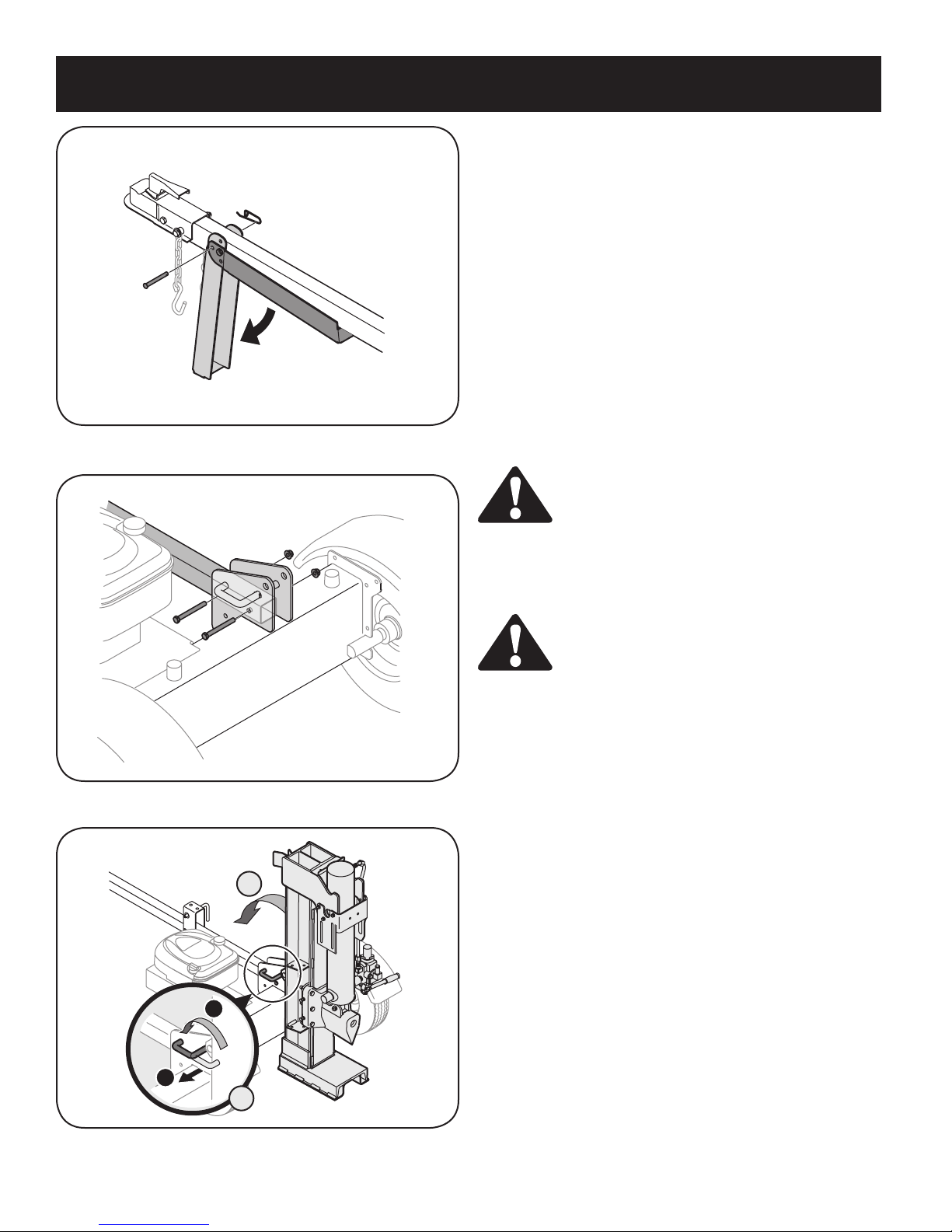
Figure 3-1
ASSEMBLY
IMPORTANT: Your log splitter is shipped with motor oil in the engine.
However, you MUST check the oil level before operating. Be careful
not to overfill.
NOTE: All references in this manual to the left or right side of the log
splitter is from the operating position only.
Removing Unit From Carton
1. Pry the top, sides, and ends off crate.
2. Set panels aside to avoid tire punctures or personal injury.
3. Remove and discard plastic bag that covers unit.
4. Remove any loose parts if included with unit (i.e., operator’s
manual, etc.)
5. Cut and remove straps which secure parts to bottom of crate.
Unbolt any remaining parts which may be bolted to the bottom of
the crate.
WARNING: Use extreme caution unpacking this
machine. Some components are very heavy and will
require additional people or mechanical handling
equipment.
Figure 3-2
B
Loose Parts In Carton
1. Tongue Assembly
WARNING: Disconnect the spark plug wire and
ground against the engine to prevent unintended
starting.
Assembling the Tongue
Attaching the Jack Stand
The jack stand is shipped in the transport position.
1. Remove the spring clip and clevis pin and pivot the jack stand
towards the ground to the operating position.
2. Secure the jack stand in position with the clevis pin and spring clip.
See Figure 3-1.
Attaching the Tongue
1. With the log splitter still standing upright, remove two hex bolts and
hex nuts from the tank bracket. See Figure 3-2.
2. Align the holes in the tongue with the holes in the tank bracket and
secure with hardware just removed. See Figure 3-2.
2
1
A
Figure 3-3
NOTE: High pressure hose must be above the tongue assembly.
Connecting Cylinder to Beam
The log splitter is shipped with the beam in the vertical position.
1. Pull out the vertical beam lock, rotate it back, and pivot the beam to
the horizontal position until it locks. See Figure 3-3.
6
Page 7
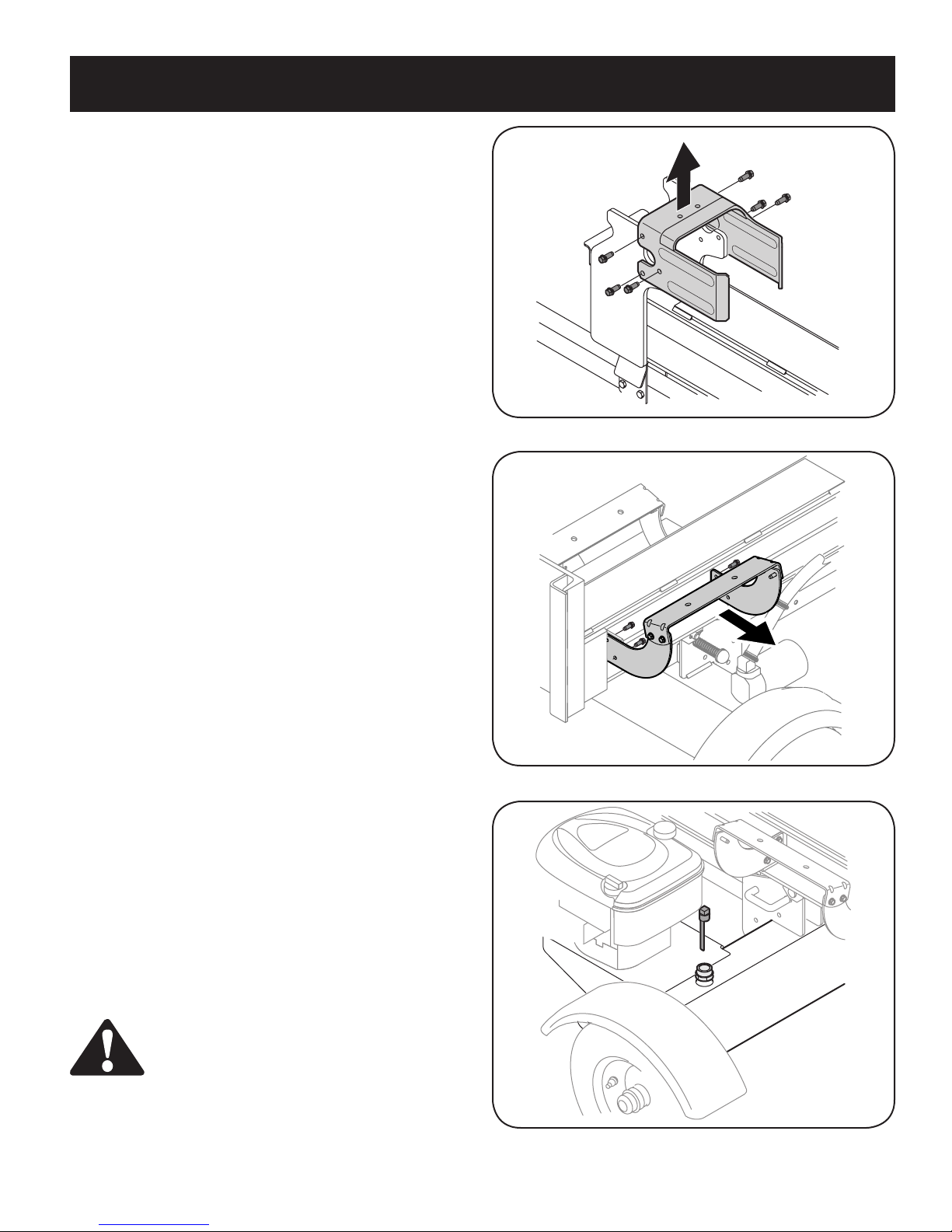
ASSEMBLY
2. Disconnect the dislodger from the beam weld bracket by removing
the six hex screws. See Figure 3-4.
3. Disconnect the log cradle from the beam on the side of the control
valve. See Figure 3-5.
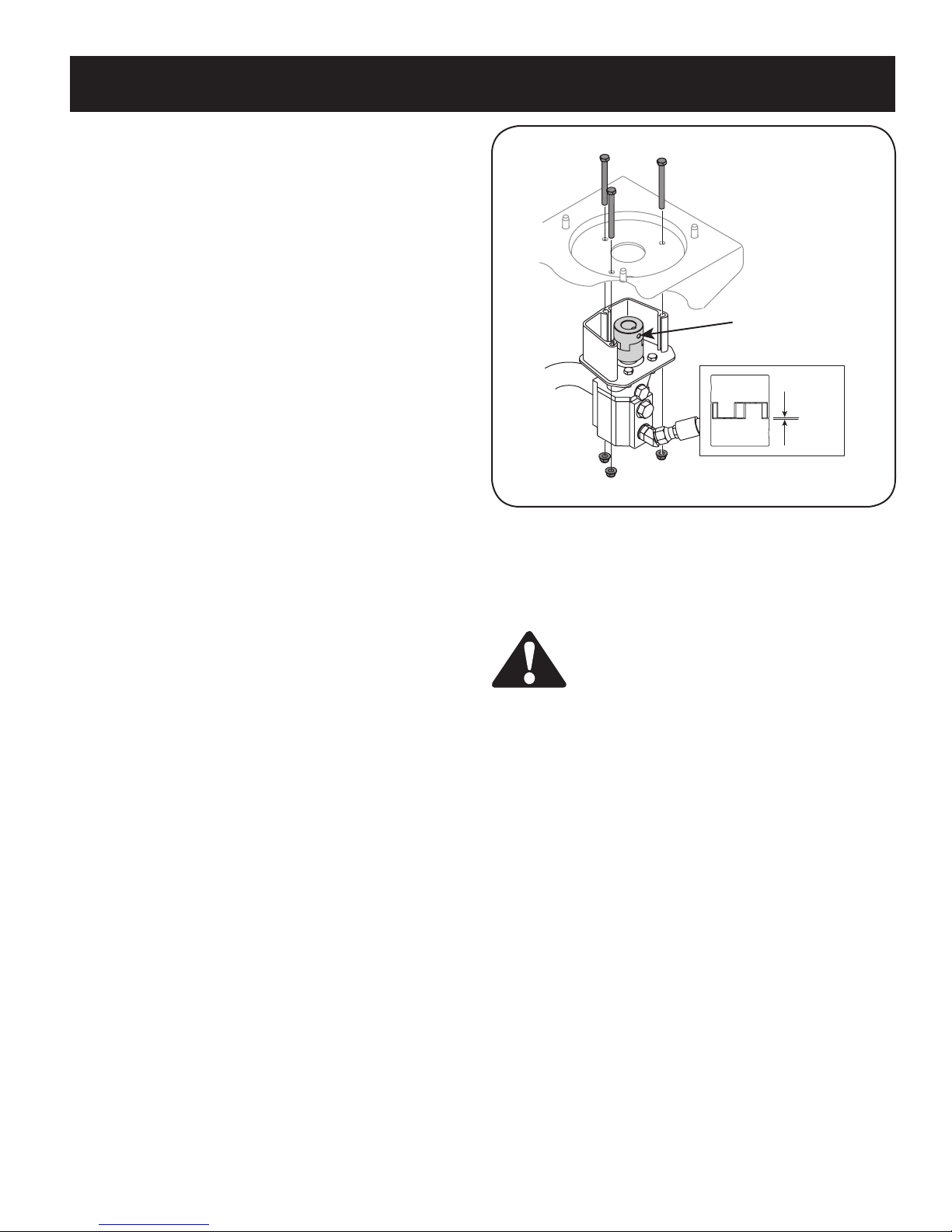
4. Lift and slide the cylinder up to the top of beam and into the weld
brackets.
5. Attach the dislodger over the wedge assembly and secure with
hardware, previously removed, to the weld brackets.
NOTE: Once the six hex screws are tightened, there may be a slight
gap between the dislodger and the weld brackets. This gap is normal.
6. Reattach the log cradle to the side of the beam with the control
valve, aligning the ends of the cradle with the beam flanges.
7. Roll log splitter off the bottom crate.
Preparing the Log Splitter
1. Lubricate the beam area (where the splitting wedge will slide) with
engine oil; do not use grease.
2. Remove vented reservoir dipstick, which is located in front of the
engine on top of the reservoir tank. See Figure 3-6.
IMPORTANT: The log splitter may have been shipped and primed
with hydraulic fluid in the reservoir tank. However, you MUST check
the fluid level before operating. If not filled, proceed with the following
steps:
3. Fill the reservoir tank with hydraulic fluid included with this unit (if
equipped) or approved fluids which include Dexron® III / Mercon®
III automatic transmission fluid, a 10 Weight AW hydraulic oil or
Pro-Mix™ AW-32 Hydraulic Oil.
4. Check fluid level using the dipstick. See Figure 3-6. Do not overfill.
5. Replace vented dipstick securely, tightening it until the top of the
threads are flush with top of the pipe.
6. Disconnect the spark plug and prime the pump by pulling the recoil
starter as far as it will go. Repeat approximately 10 times.
7. Reconnect the spark plug wire and start engine following instruc
tions in the OPERATION section.
8. Use control handle to engage the wedge to the farthest extended
position. Then retract the wedge.
9. Refill tank as specified on the dipstick.
-
Figure 3-4
Figure 3-5
NOTE: Failure to refill the tank will void unit’s warranty.
10. Extend and retract the wedge 12 complete cycles to remove
trapped air in the system (the system is “self-bleeding”).
11. Refill reservoir within range marked on the dipstick.
WARNING: Much of the original fluid has been
drawn into the cylinder and hoses. Make certain
to refill the reservoir to prevent damage to the
hydraulic pump.
NOTE: Some fluid may overflow from the vent plug as the system
builds heat and the fluid expands and seeks a balanced level.
Figure 3-6
7
Page 8
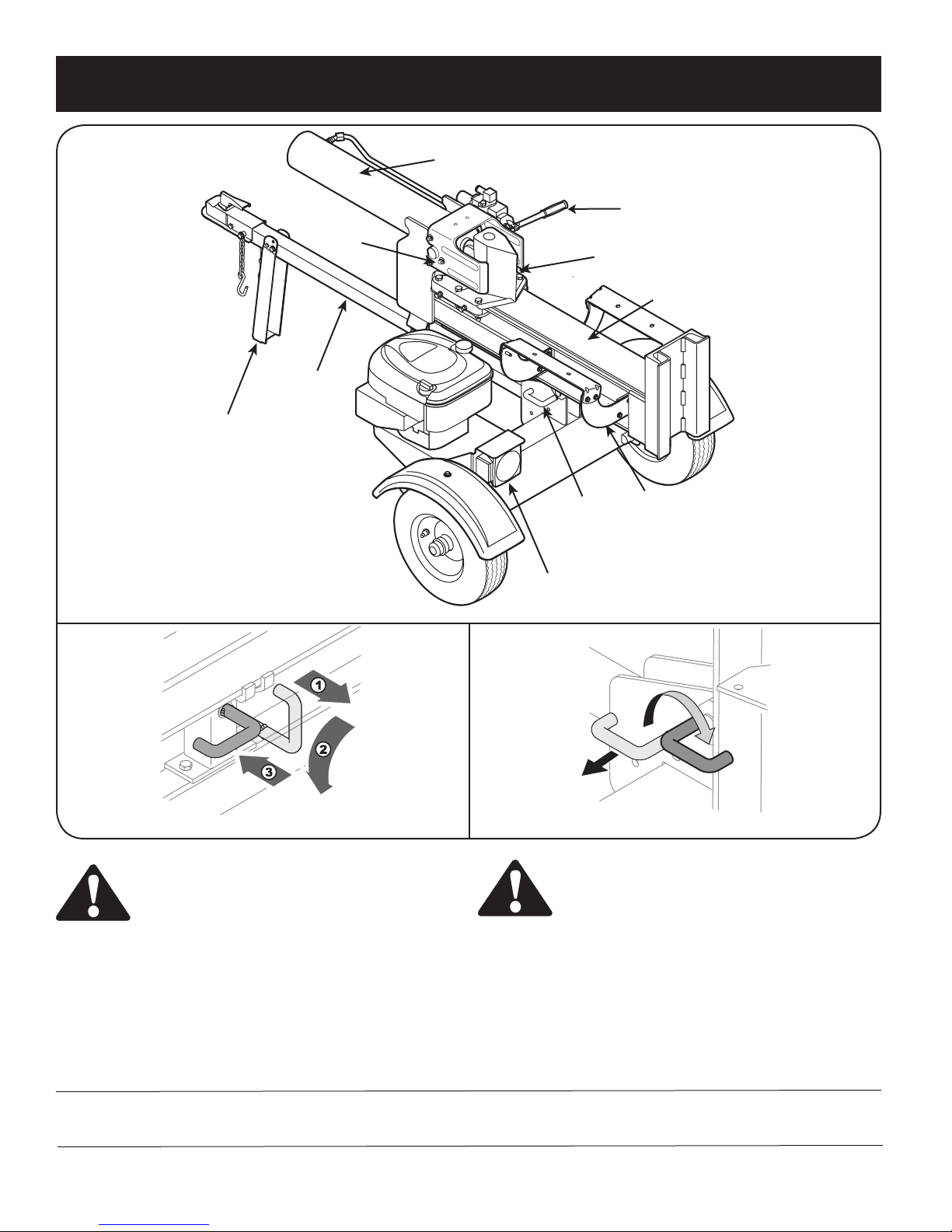
OPERATION
Cylinder
Jack Stand
Log
Dislodger
Tongue
Wedge
Vertical
Beam
Lock
Tail Light
(If Equipped)
Control Handle
Beam Assembly
Log Cradle
Horizontal Beam Lock
WARNING: Read this operator’s manual and safety
rules before operating your log splitter. Compare
the illustrations below with your equipment to
familiarize yourself with the location of various
controls and adjustments. Save this manual for
future reference.
The operation of any log splitter can result in
foreign objects being thrown into the eyes, which
can result in severe eye damage. Always wear safety
glasses, for operating this equipment or while
performing any adjustments or repairs on it.
Meets ANSI Safety Standards
Craftsman Yard Vacuums conform to the safety standard of the American National Standards Institute (ANSI).
Vertical Beam Lock
Figure 4-1
WARNING: Be familiar with all controls and their
proper operation. Know how to stop the machine
and disengage them quickly.
Beam Locks
These two locks, as their name suggests, are used to secure the beam
in the horizontal or the vertical position. The vertical beam lock is
located next to the oil filter. The horizontal beam lock is located on the
beam support latch bracket. See Figure 4-1.
8
Page 9
OPERATION
Engine Controls
Stop Switch
Push button to ON prior to choking for engine start; push to OFF to
shut engine down.
Choke Control
The choke control is used to choke off the carburetor and assist in
starting the engine.
To return
wedge
Starter Handle
The starter handle is located on the engine. Pull the starter handle to
start engine.
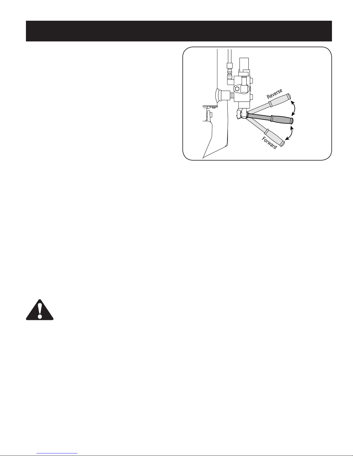
Control Handle
The control handle has three positions. See Figure 4-2.
• FORWARD: Move control handle FORWARD or DOWN to move
wedge to split wood.
NOTE: Control handle will return to neutral position as soon as handle
is released.(Forward Position only)
NEUTRAL: Release the control handle or move the lever to neutral
•
position to stop the wedge movement.
•
REVERSE: Move control handle BACK or UP to return the
wedge toward the cylinder. The control handle stays in the return
(Reverse) position and returns to neutral automatically when fully
retracted.
NOTE: Reverse position may also be operated back to neutral position
manually, if necessary.
Gas and Oil Fill-Up
IMPORTANT: Your log splitter may be shipped with motor oil in the
engine. You MUST check the oil level before operating. Be careful not
to overfill.
WARNING: Use extreme care when handling
gasoline. Gasoline is extremely flammable and the
vapors are explosive. Never fuel machine indoors or
while the engine is hot or running.
Oil
1. Remove oil fill dipstick.
2. Check the oil level making certain not to rub the dipstick along the
inside walls of the oil fill tube. This would result in a false dipstick
reading. Refill to FULL mark on dipstick, if necessary. Replace
dipstick and tighten.
3. If necessary, with the log splitter on level ground, use a funnel to fill
engine with oil to FULL mark on dipstick. Be careful not to overfill.
Overfilling will cause the engine to smoke profusely and will result
in poor engine performance.
Neutral
To stop
wedge
To split wood
Figure 4-2
4. Check oil level three times prior to starting engine to be certain
you’ve gotten an accurate dipstick reading. Running the engine with
too little oil can result in permanent engine damage.
Gasoline
1. Remove fuel cap from the fuel tank.
2. Make sure the container from which you will pour the gasoline is
clean and free from rust or foreign particles. Never use gasoline
that may be stale from long periods of storage in its container.
Gasoline that has been sitting for any period longer than four weeks
should be considered stale.
3. Fill fuel tank with about 1.5 quarts of clean, fresh, lead-free grade
automotive gasoline. DO NOT use Ethly or high octane gasoline.
NOTE: Gasoline can be added to the engine when the log splitter is
in either the horizontal or vertical position. However, there are less
obstructions when the unit is in the vertical position.
NOTE: Do not use gasoline containing methanol. Gasoline containing
up to about 10% ethanol or up to 15% methyl tertiary butyl ether
(MTBE) may be used, but will require special care when engine is left
unused for extended period.
4. Replace fuel cap.
NOTE: To avoid engine problems, the fuel system should be emptied
before storage for 30 days or longer. Drain the gas tank, start the
engine and let it run until the fuel lines and carburetor are empty. Use
fresh fuel next season. See STORAGE section for additional information.
9
Page 10
OPERATION
Figure 4-3
Stopping Engine
1. Push stop switch to OFF.
2. Disconnect spark plug wire and ground against the engine to
prevent unintended starting.
WARNING: When starting a warm engine, the muffler and surrounding areas are hot and can cause a
burn. Do not touch.
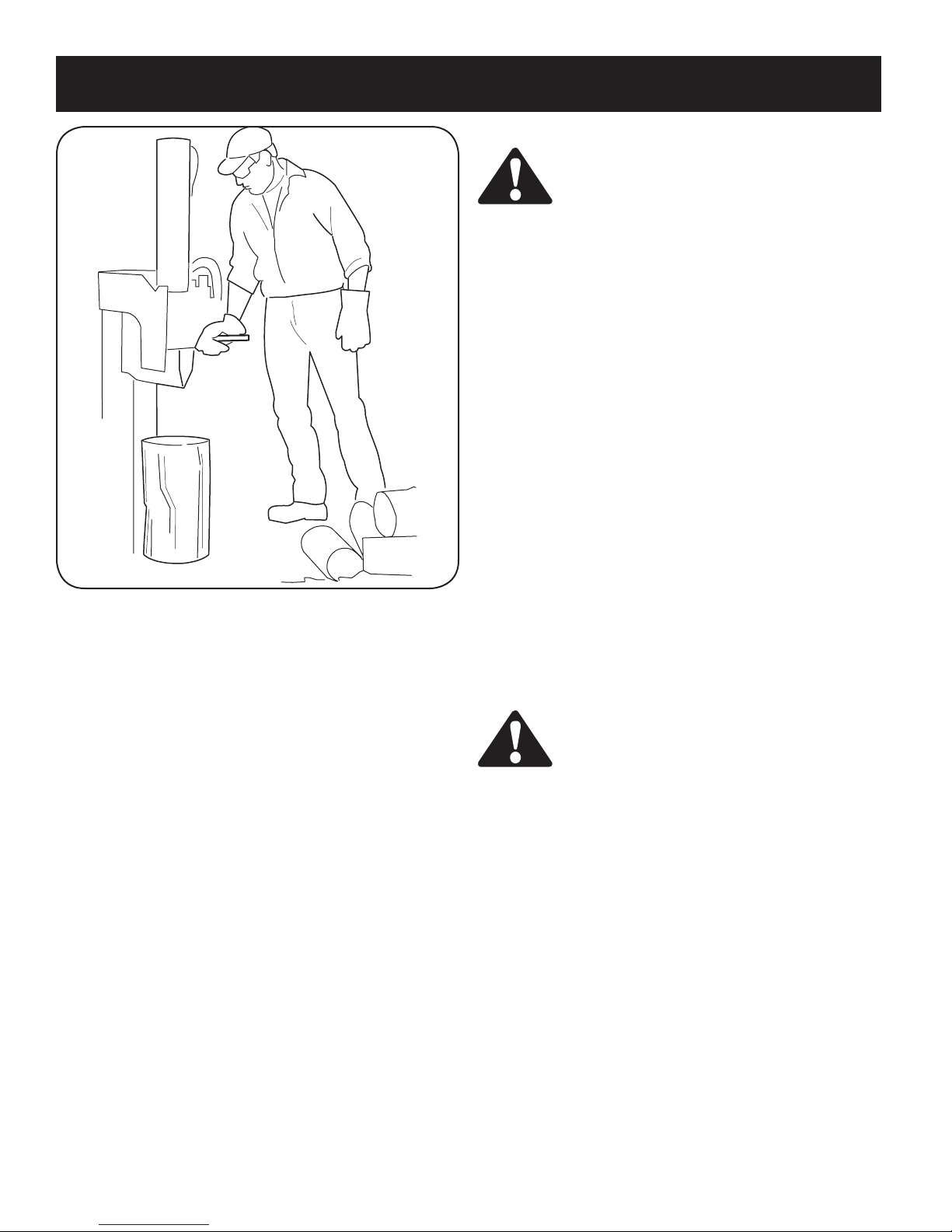
Using the Log Splitter
1. Place the log splitter on level, dry ground.
2. Place the beam in either the horizontal or vertical position and lock
in place with the appropriate locking rod.
3. Block the front and back of both wheels.
4. Place the log against the end plate and only split wood in the
direction of the grain.
5. To stabilize the log, place your hand only on sides of log.
place hand on the end between the log and the splitting
wedge.
6. Only one adult should stabilize the log and operate the control
handle, so the operator has full control over the log and the splitting
wedge.
Control Handle
1. Move control handle FORWARD or DOWN to split wood.
2. Release the control handle to stop the wedge movement.
3. Move control handle BACK or UP to return the wedge.
Log Dislodger
The log dislodger is designed to remove any partially split wood from
the wedge. This may occur while splitting large diameter wood or
freshly cut wood.
Never
Starting Engine
1. Attach spark plug wire to spark plug. Make certain the metal cap on
the end of the spark plug is fastened securely over the metal tip on
the spark plug.
2. Push stop switch to ON.
3. Move choke control to CHOKE position.
4. Grasp starter handle and pull rope out slowly until engine reaches
start of compression cycle (rope will pull slightly harder at this
point).
5. Pull rope with a rapid, continuous, full arm stroke. Keep a firm grip
on starter handle. Let rope rewind slowly.
6. Repeat, if necessary, until engine starts. Slowly adjust choke
toward RUN position. Wait until engine runs smoothly before each
choke adjustment.
7. If engine falters, move control lever to CHOKE position, then slowly
back to RUN position.
8. If weather is cold, run wedge up or down beam 6 to 8 times to
circulate the hydraulic fluid.
WARNING: Never remove partially split wood from
the wedge with your hands. Fingers may become
trapped between split wood.
1. To remove partially split wood from wedge, move control handle to
REVERSE position until wedge is fully retracted to allow split wood
portion to contact the log dislodger.
2. Once removed from wedge with log dislodger, split wood from
opposite end or in another location.
Vertical Position
1. Pull the horizontal beam lock out to release the beam and pivot the
beam to the vertical position.
2. To lock the beam in the vertical position, pull out on the vertical
beam lock and rotate it to secure the beam. See Figure 4-1.
3. Stand in front of the unit to operate the control handle and to
stabilize the log. See Figure 4-3.
10
Page 11
OPERATION
Horizontal Position
1. Pull the vertical beam lock out and rotate it down. See Figure 4-1.
Pivot beam to the horizontal position. The beam will lock automatically in horizontal position.
2. Stand behind the reservoir tank to operate control handle and to
stabilize the log.
Operating Tips
Always:
1. Use clean fluid and check fluid level regularly.
2. Use an approved hydraulic fluid. Approved fluids include Dexron®
III / Mercon® III automatic transmission fluid, a 10 Weight AW
hydraulic oil or Pro-Mix™ AW-32 Hydraulic Oil.
3. Use a filter (clean or replace regularly).
4. Use a breather cap on fluid reservoir.
5. Make sure pump is mounted and aligned properly.
6. Use a flexible “spider” type coupling between engine and pump
drive shafts.
7. Keep hoses clear and unblocked.
8. Bleed air out of hoses before operating.
9. Flush and clean hydraulic system before restarting after servicing.
10. Use “pipe dope” on all hydraulic fittings.
11. Allow time for warm-up before splitting wood.
12. Prime the pump before initial start-up by turning over the engine
with spark plug disconnected.
13. Split wood along the grain (lengthwise) only.
Never:
1. Use when fluid is below 20° F or above 150° F.
2. Use a solid engine /pump coupling.
3. Operate through relief valve for long.
4. Attempt to adjust unloading or relief valve settings without pressure
gauges.
5. Operate with air in hydraulic system.
6. Use teflon tape on hydraulic fittings.
7. Attempt to cut wood across the grain.
8. Attempt to remove partially split wood from the wedge with your
hands. Fully retract wedge to dislodge wood with log dislodger.
Figure 4-4
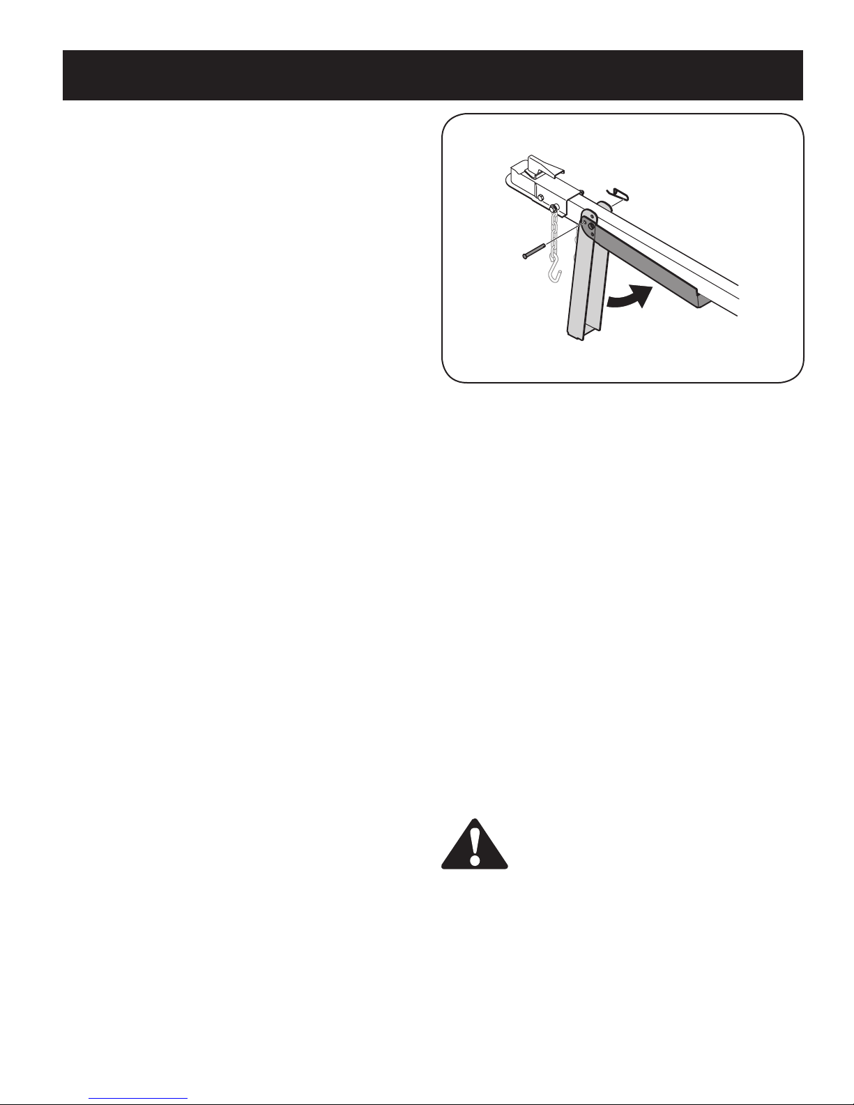
Transporting the Log Splitter
IMPORTANT: Always turn fuel valve to OFF position before transporting the log splitter.
1. Lower the beam to its horizontal position. Make certain the beam is
locked securely with the horizontal beam lock.
2. Remove spring clip and clevis pin from jack stand.
3. Support the tongue and pivot the jack stand up against the tongue.
See Figure 4-4.
4. Secure with the spring clip and clevis pin previously removed. See
Figure 4-4.
5. Attach coupler hitch to a class I or higher 2” ball on a towing
vehicle; latch securely.
If coupler hitch does not fit on ball: Turn adjustment nut one
a.
turn counter-clockwise.
b.
If coupler hitch is too loose on ball: Turn adjustment nut one
turn clockwise.
6. Connect the safety chains to the towing vehicle.
7. Plug in the tail lights, if so equipped, to the tail light connector on
the tow vehicle.
WARNING: Do not tow faster than 45mph and check
local, state, and federal requirements before towing
on any public road.
NOTE: Use caution when backing up. It is recommended to use a
spotter outside the vehicle.
11
Page 12
SERVICE & ADJUSTMENTS
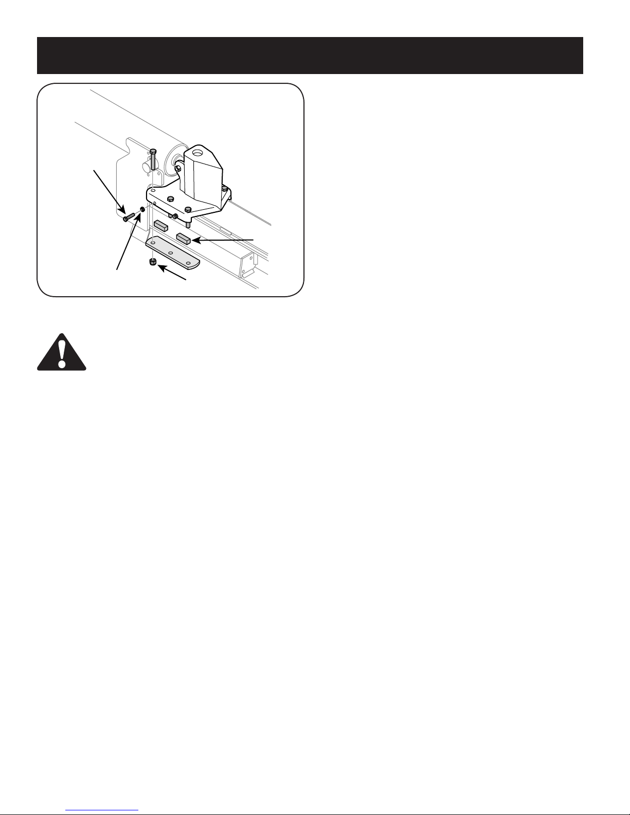
Gib Adjustment
Periodically remove and replace the “gibs” (spacers) between the
wedge assembly and the back plate.
NOTE: The gibs may be rotated and/or turned over for even wear.
Adjustment
Bolt
Gib
Jam Nut
Lock Nut
Figure 5-1
WARNING: Do not at any time make any adjustments without first stopping engine, disconnecting
spark plug wire, and grounding it against the
engine. Always wear safety glasses during operation or while performing any adjustments or repairs.
Wedge Assembly Adjustment
As normal wear occurs and there is excessive “play” between the
wedge and beam, adjust the bolts on the side of the wedge assembly
to eliminate excess space between the wedge and the beam.
1. Loosen the jam nuts on the two adjustment bolts on the side of the
wedge. See Figure 5-1.
2. Turn the adjustment bolts in until snug and then back them off
slowly (approximately 1.5 turns) until the wedge assembly will slide
on the beam.
3. Re-tighten the jam nuts securely against the side of the wedge to
secure the adjustment bolts in this position.
1. Loosen the lock nuts under each back plate and slide the gibs out.
See Figure 5-1.
2. Turn or replace the gibs.
3. Reassemble the back plate and secure with the lock nuts.
4. Readjust the bolts on the side of the wedge assembly.
Hose Clamps
• Check, before each use, if hose clamps on the suction hose
(attached to the side of the pump) are tight. Check the hose clamps
on the return hose at least once a season.
Flexible Pump Coupler
The flexible pump coupler is a nylon “spider” insert, located between
the pump and the engine shaft. Over time, the coupler will harden and
deteriorate.
Replace the coupler if you detect vibration or noise coming from the
area between the engine and the pump. If the coupler fails completely,
you will experience a loss of power.
IMPORTANT: Never hit the engine shaft in any manner, as a blow will
cause permanent damage to the engine.
12
Page 13
SERVICE & ADJUSTMENTS
1. Remove three nuts that secure the pump to the coupling shield.
Two nuts are at the bottom corners and one is in the top center.
See Figure 5-2.
2. Remove the pump.
3. Rotate the engine by slowly pulling starter handle until engine
coupling half set screw is visible. Loosen set screw using allen
wrench and slide coupling half off engine shaft.
4. Loosen set screw on pump coupling half and remove coupling half.
5. Slide new engine coupling half onto the engine shaft until the end of
the shaft is flush with the inner portion of the coupling half. (There
must be space between the end of the engine support bracket and
coupling half). Tighten set screw.
6. Install pump coupling half and key on pump shaft. Rotate coupling
half until set screw faces opening in shield. Do not tighten set
screw.
7. Install nylon “spider” onto engine coupling half.
8. Align pump coupling half with nylon “spider” by rotating engine
using starter handle. Slide coupling half into place while guiding
three mounting bolts through holes in pump support bracket.
9. Secure with nuts removed earlier.
10. Set.010” to.060” clearance/gap between the nylon “spider” and
the engine coupling half by sliding a feeler gauge or matchbook
cover between the nylon “spider” and the engine coupling half and
moving pump coupling half as needed. Secure pump coupling half
with set screw. See Figure 5-2.
NOTE: Make certain proper clearance/gap is obtained before tightening set screw.
Set Screw
Side View-Coupler
.0600
.0100
Figure 5-2
Tires
See sidewall of tire for recommended pressure. Under any circumstances do not exceed manufacturer’s recommended psi. Maintain
equal pressure on all tires.
WARNING: Excessive pressure when seating beads
may cause tire /rim assembly to burst with force
sufficient to cause serious injury. Refer to sidewall
of tire for recommended pressure.
13
Page 14

MAINTENANCE
Maintenance Schedule
TASKS
Lubricate Beam &
Wedge
Change Hydraulic
Fluid
Change Hydraulic
Filter
Clean Reservoir
Screen
Check Reservoir
Fluid
Check Engine Oil
Change Engine Oil
Service Air Cleaner
Before
Each Use
First 5
Hours
Every 25
Hours
Every 50
Hours
Every 100
Hours
SERVICE DATES
Service Spark Plug
Clean Engine
WARNING: Do not at any time make any adjustments without first stopping engine, disconnecting
spark plug wire, and grounding it against the
engine. Always wear safety glasses during operation or while performing any adjustments or repairs.
Figure 5-1
General Recommendations
1. Always observe safety rules when performing any maintenance.
2. The warranty on this log splitter does not cover items that have
been subjected to operator abuse or negligence. To receive full
value from the warranty, operator must maintain the equipment as
instructed in this manual.
3. Some adjustments will need to be made periodically to maintain
your equipment properly.
4. Follow the maintenance schedule (Figure 5-1).
5. Periodically check all fasteners and make sure they are tight.
14
Page 15
MAINTENANCE
Hydraulic Fluid and Inlet Filter
• Check the hydraulic fluid level in the log splitter reservoir tank
before each use. Maintain fluid level within the range specified on
the dipstick at all times.
• Change the hydraulic fluid in the reservoir every 100 hours of
operation. Follow the steps below:
1. Disconnect the suction hose from the bottom of the reservoir tank.
2. Carefully unthread the inlet filter and clean it with penetrating oil.
See Figure 5-2.
3. Allow the fluid to drain into a suitable container.
4. Reinsert the filter and refill the reservoir with three gallons of
oil. Approved fluids include Dexron® III / Mercon® III automatic
transmission fluid, a 10 Weight AW hydraulic oil or Pro-Mix™
AW-32 Hydraulic Oil.
• Maintain fluid level within the range specified on the dipstick at all
times.
NOTE: Always dispose of used hydraulic fluid and engine oil at
approved recycling centers only.
• Contaminants in fluid may damage the hydraulic components.
Flushing the reservoir tank and hoses with kerosene whenever
service is performed on the tank, hydraulic pump or valve is
recommended. Any repair to the hydraulic components should be
performed by a Sears Service Center.
Figure 5-2
Engine
Check Engine Oil
1. Stop engine and wait several minutes before checking oil level.
2. Remove oil fill dipstick.
3. Check oil level on dipstick. With engine on level ground, the oil
must be to FULL mark on dipstick.
4. Replace dipstick and tighten.
WARNING: Use extreme caution when working with
kerosene. It is an extremely flammable fluid.
Hydraulic Filter
• Change the hydraulic filter every 50 hours of operation. Use only a
10 micron hydraulic filter. Order part number 723-0405.
Beam and Splitting Wedge
• Lubricate both sides of the beam (where it comes into contact with
the splitting wedge), before each use, with engine oil. The wedge
plate on the log splitter is designed so the gibs on the side of the
wedge plate can be removed and rotated and/or turned over for
even wear.
• Make certain to readjust the adjustment bolts so wedge moves
freely, but no excess space exists between the wedge plate and the
beam.
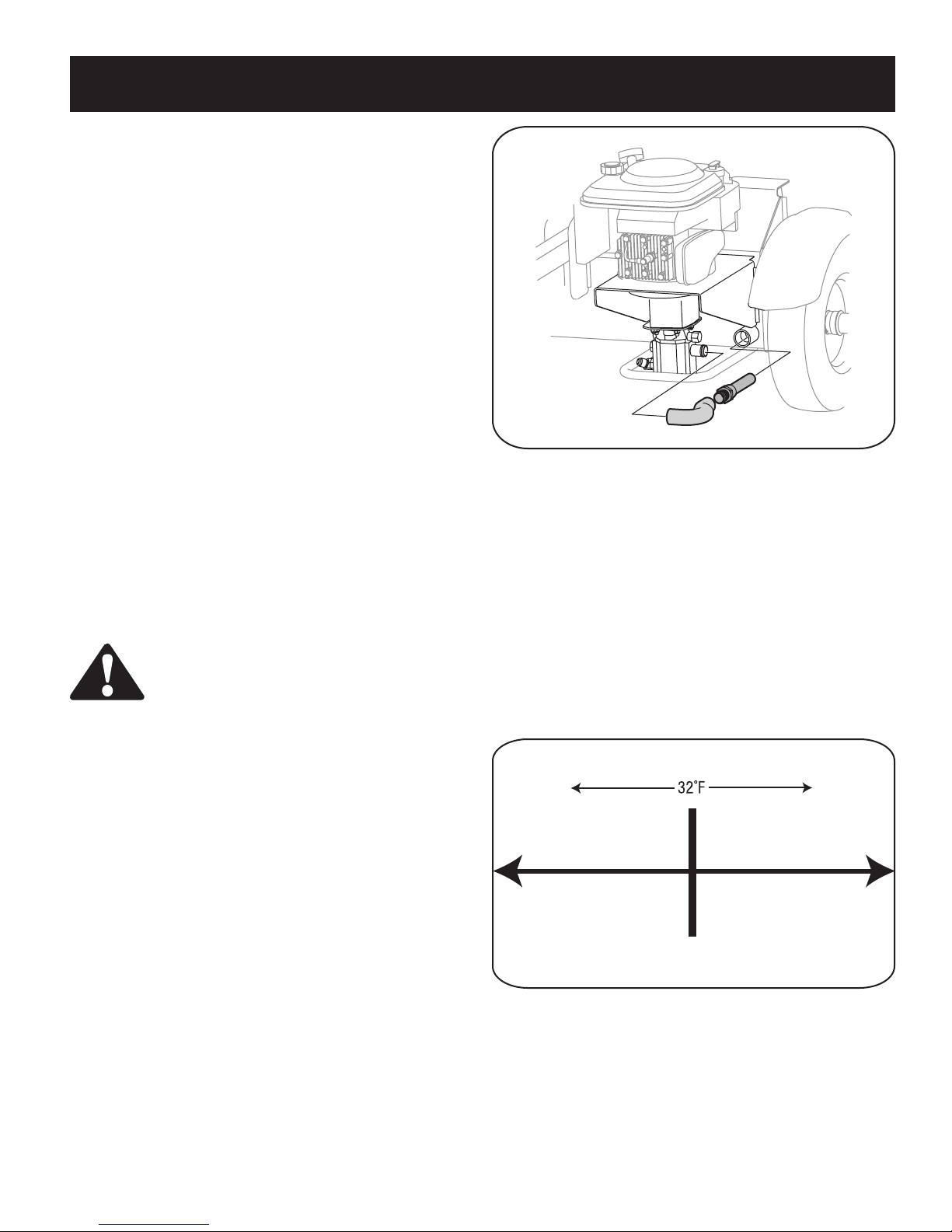
Changing Engine Oil
Only use high quality detergent oil rated with API service classification
SF, SG, or SH. Select the oil’s SAE viscosity grade according to the
expected operating temperature. Follow the chart below:
Colder
5W30
SAE 30
Warmer
Oil Viscosity Chart
15
Page 16

MAINTENANCE
Service cartridge every 25 operating hours or every season. Service
cartridge more often under dusty conditions.
2
1
3
To Service Air Filter
1. Loosen air cleaner cover screw, but do not remove screw from
cover. Swing cover down to remove from hinge.
2. Inspect filter for discoloration or dirt accumulation. If either is
present, proceed as follows:
a. Clean inside of body and cover thoroughly and remove cartridge.
b. Reassemble new cartridge in the body. Swing cover down and
tighten the screw loosened earlier.
1. .030 (.76 mm) Gap
2. Electrodes
3. Porcelain
Figure 5-3
NOTE: Although multi-viscosity oils (5W30, 10W30, etc.) improve
starting in cold weather, they will result in increased oil consumption
when used above 32°F. Check your engine oil level more frequently to
avoid possible engine damage from running low on oil.
Change engine oil after the first five hours of operation, and every 50
hours thereafter. Change oil every 25 hours of operation if the engine
is operated under heavy load or in high ambient temperatures.
To Drain Oil
Drain oil while engine is warm. Follow the instructions given below.
1. To drain the gas tank, start the engine and let it run until the fuel
line and carburetor are empty.
2. Remove drain plug on the side of the engine and drain oil into a
suitable container.
3. When engine is drained of all oil, replace drain plug and refill with
approximately 20 oz. of fresh oil. Refer to Gas And Oil Fill-up in
OPERATION section.
Service Air Cleaner
The air cleaner prevents damaging dirt, dust, etc., from entering the
carburetor and being forced into the engine and is important to engine
life and performance.
Temperature of muffler and nearby areas may
exceed 150˚ F(65˚C). Avoid these areas.
Service Spark Plug
• Clean the spark plug and reset the gap to.030” at least once a
season or every 50 hours of operation.
• Clean area around spark plug. Remove and inspect spark plug.
• Replace if electrodes are pitted, burned or the porcelain is cracked.
• Check electrode gap with wire feeler gauge and reset gap to.030
inches. See Figure 5-3.
NOTE: Do not sand spark plug. Spark plug should be cleaned with a
wire brush and a commercial solvent.
Clean Engine
• Clean engine periodically, by removing dirt and debris with a cloth
or brush.
NOTE: Cleaning with a forceful spray of water is not recommended as
water could contaminate the fuel system.
• To ensure smooth operation of the engine, keep the governor
linkage, springs, and controls free of debris.
• Every 100 hours of operation, remove combustion deposits from
top of cylinder, head, top of piston, and around valves.
WARNING: Never run the engine without an air
cleaner completely assembled.
16
Page 17

OFF-SEASON STORAGE
Prepare your log splitter for storage at the end of the season or if the
log splitter will not be used for 30 days or more.
WARNING: Never store machine with fuel in the
fuel tank inside of building where fumes may reach
an open flame or spark or where ignition sources
are present such as hot water and space heaters,
furnaces, clothes dyers, stoves, electric motors, etc.
NOTE: Yearly check-up by your local Sears service center is a good
way to ensure your log splitter will provide maximum performance next
season.
Log Splitter
1. Clean the log splitter thoroughly.
2. Wipe unit with an oiled rag to prevent rust, especially on the wedge
and the beam.
Engine
IMPORTANT: It is important to prevent gum deposits from forming in
essential fuel system parts such as carburetor, fuel filter, fuel hose,
or tank during storage. Also, alcohol blended fuels (called gasohol or
using ethanol or methanol) can attract moisture which leads to separation and formation of acids during storage. Acidic gas can damage the
fuel system of an engine while in storage.
1. Drain the fuel tank. Always drain fuel into approved container
outdoors away from open flame. Be sure the engine is cool. Do not
smoke while handling the fuel.
2. Start the engine and let it run until the fuel lines and carburetor are
empty.
IMPORTANT: Never use engine or carburetor cleaner products in the
fuel tank or permanent damage may occur. Use fresh fuel next season.
3. Remove spark plug, pour approximately 1/2 oz. of engine oil into
cylinder and crank slowly to distribute oil.
4. Replace spark plug.
NOTE: Fuel stabilizer is an acceptable alternative in minimizing for
formation of fuel gum deposits during storage.
Please follow the instructions below for storing your log splitter with
fuel and stabilizer in the engine:
1. Add stabilizer to gasoline in fuel tank or storage container. Always
follow the mix ratio found on stabilizer container.
2. Run engine at least 10 minutes after adding stabilizer to allow the
stabilizer to reach the carburetor.
IMPORTANT: Do not drain the gas tank and carburetor if using fuel
stabilizer. Drain all the oil from the crankcase (this should be done
after the engine has been operated and is still warm) and refill the
crankcase with fresh oil.
Other
• Do not store gasoline from one season to another.
• Replace your gasoline can if it starts to rust.
• Store unit in a clean, dry area. Do not store next to corrosive
materials, such as fertilizer.
• Wipe equipment with an oiled rag to prevent rust.
17
Page 18

Engine fails to start
TROUBLESHOOTING
CauseProblem Remedy
1. Spark plug wire disconnected.
2. Fuel tank empty or stale fuel.
3. Choke lever not in CHOKE position.
4. Faulty spark plug.
5. Blocked fuel line.
6. Dirty air cleaner.
1. Connect wire to spark plug.
2. Fill tank with clean, fresh gasoline.
3. Move choke to CHOKE position.
4. Service spark plug following
instructions in the maintenance
section.
5. Clean fuel line.
6. Service air cleaner following
instructions in the maintenance
section.
Engine runs erratic
Engine Overheats
Cylinder rod will not
move
1. Unit running with CHOKE applied, if so
equipped.
2. Spark plug wire loose.
3. Blocked fuel line or stale fuel.
4. Water or dirt in fuel system.
5. Dirty air cleaner.
6. Carburetor not adjusted properly.
1. Engine oil level low.
2. Dirty air cleaner.
3. Carburetor not adjusted properly.
1. Broken drive shaft.
2. Shipping plugs left in hydraulic hoses.
3. Set screws in coupling not adjusted
properly.
4. Loose shaft coupling.
5. Gear sections damaged.
6. Damaged relief valve.
7. Hydraulic lines blocked.
8. Incorrect oil level.
9. Damaged or blocked directional valve.
1. Move choke lever to RUN position.
2. Connect and tighten spark
plug wire.
3. Clean fuel line; fill tank with clean,
fresh (less than 30 days old)
gasoline.
4. Drain fuel tank. Refill with
fresh fuel.
5. Clean or replace air cleaner.
6. Contact Sears service center.
1. Fill crankcase with proper oil.
2. Service air cleaner following
instructions in the maintenance
section.
3. Contact Sears service center.
1. Return unit to Sears service center.
2. Disconnect hydraulic hoses,
remove shipping plugs, reconnect
hoses.
3. See operator’s manual for correct
adjustment.
4. Correct engine/pump alignment as
necessary.
5. Return unit to Sears service center.
6. Return unit to Sears service center.
7. Flush and clean hydraulic system.
8. Check oil level. Refill if necessary.
9. Return unit to Sears service center.
NOTE: This section addresses minor service issues. For further details, contact Sears service information line by calling
1-800-4-MY-HOME.
18
Page 19

Slow cylinder shaft
speed while extending
and retracting.
Leaking Cylinder
TROUBLESHOOTING
CauseProblem Remedy
1. Gear sections damaged.
2. Excessive pump inlet vacuum.
3. Slow engine speed.
4. Damaged relief valve.
5. Incorrect oil level.
6. Contaminated oil.
7. Directional valve leaking internally.
8. Internally damaged cylinder.
1. Broken seals.
2. Scored cylinder.
1. Return unit to Sears service center.
2. Make certain pump inlet hoses are
clear and unblocked. Use short,
large diameter inlet hoses.
3. Return unit to Sears service center.
4. Return unit to Sears service center.
5. Check oil level. Refill if necessary.
6. Drain oil, clean reservoir, and refill.
7. Return unit to Sears service center.
8. Return unit to Sears service center.
1. Return unit to Sears service center.
2. Return unit to Sears service center.
Engine runs but wood
will not split or wood
splits too slowly
Engine stalls during
splitting
Engine will not turn or
stalls under low load
conditions
Leaking pump shaft
seal
Will not split logs
1. Small gear section damaged.
2. Pump check valve leaking.
3. Excessive pump inlet vacuum.
4. Incorrect oil level.
5. Contaminated oil.
6. Directional valve leaking internally.
7. Overloaded cylinder.
8. Internally damaged cylinder.
1. Low horsepower/weak engine.
2. Overloaded cylinder.
1. Engine/pump misalignment.
2. Frozen or seized pump.
3. Low horsepower/weak engine.
4. Hydraulic lines blocked.
5. Blocked directional valve.
1. Broken drive shaft.
2. Engine/pump misalignment.
3. Gear sections damaged.
4. Poorly positioned shaft seal.
5. Plugged oil breather.
1. Reservoir fluid level low.
1. Return unit to Sears service center.
2. Return unit to Sears service center.
3. Make certain pump inlet hoses are
clear and unblocked. Use short,
large diameter inlet hoses.
4. Check oil level. Refill if necessary.
5. Drain oil, clean reservoir, and refill.
6. Return unit to Sears service center.
7. Do not attempt to split wood
against the grain.
8. Return unit to Sears service center.
1. Return unit to Sears service center.
2. Do not attempt to split wood
against the grain. If engine stalls
repeatedly, contact Sears service
center.
1. Correct alignment as necessary.
2. Return unit to Sears service center.
3. Return unit to Sears service center.
4. Flush and clean hydraulic system.
5. Return unit to Sears service center.
1. Return unit to Sears service center.
2. Correct alignment as necessary.
3. Return unit to Sears service center.
4. Return unit to Sears service center.
5. Make certain reservoir is properly
vented.
1. Refill with Dexron III automatic
transmission fluid.
NOTE: This section addresses minor service issues. For further details, contact Sears service information line by calling
1-800-4-MY-HOME.
19
Page 20

PARTS LIST
61
62
64
44
18
65
67
44
19
41
70
69
41
65
55
1
41
71
12
44
15
40
6
75
5
74
68
25
76
22
41
63
23
8
32
23
31
24
42
39
36
16
7
9
34
2
3
4
11
13
20
10
56
58
57
41
17
66
29
30
27
28
26
72
33
59
72
59
50
48
73
45
18
77
A
20
46
47
48
49
51
48
23
61
43
14
35
A
23
54
53
52
21
37
38
Page 21

Craftsman 6.5 H.P. Log Splitter Model 247.77466.1
Ref.
No.
1. 718-0769A Hydraulic Cylinder
2. 727-04166 Hydraulic Tube
3. 710-1018 Hex Cap Screw 1/2-20 x 2.75
4. 737-0192 90 Degree Solid Adapter
5. 718-0481A Control Valve
6. 737-0153 Return Elbow
7. 737-0238 Nipple Pipe 1/2-14
8. 710-1806 Hex Cap Screw 1/2-13 x 3.25
9. 719-0550A Wedge Assembly
10. 712-3058 Hex Lock Nut, 1/2-20
11. 712-0711 Hex Jam Nut 3/8-24
12. 710-0459A Hex Cap Screw 3/ 8-24 x 1.5
13. 781-0351 Adjustable Gib
14. 736-0116 Flat Washer.635 x.93 x.06
15. 712-3022 Hex Lock Nut 1/2-13
16. 681-04071 Beam Assembly
17. 710-3056 Hex Screw, 5/16-18 x 3.25
18. 710-0654A Hex Washer Screw 3/ 8-16 x 1.0
19. 781-1048A Dislodger Bracket
20. 781-0790 Back Plate
21. 737-04093 Inlet Filter
22. 727-0443 Return Hose 3/4” ID x 44” Lg.
23. 726-0132 Hose Clamp 5/8”
24. 737-0316 Filter Housing
25. 723-0405 Oil Filter
26. 734-0873 Hub Cap
27. 714-0162 Cotter Pin
28. 712-0359 Slotted Nut 3/4-16
29. 634-0186 Wheel Assembly
30. 736-0351 Flat Washer.760 ID x.500 OD
31. 737-0312 Adapter 3 /4-14
32. 781-0526A Hose Guard
33. 737-0348A Vented Dipstick
34. 711-1587 Clevis Pin
35. 781-0690 Lock Rod
36. 714-0470 Cotter Pin
37. 726-0214 Push Cap
38. 732-0583 Compression Spring
39. 781-04180 Log Tray Bracket
Part No. Description
Ref.
No.
40. 710-0650 TT Screw, 5/16-18 x.875
41. 712-04065 Flange Lock Nut, 3/8-16
42. 781-04129 Log Tray
43. 681-04040 Frame Assembly
44. 710-0521 Hex Bolt 3/8-16 x 3”
45. 719-0353 Coupling Shield
46. 714-0122 Square Key 3/16” x.75
47. 718-04145 Flexible Coupling
48. 712-04063 Flange Lock Nut, 5/16-18
49. 781-0097 Rear Coupling Support Bracket
50. 781-1024 Fender Mounting Bracket
51. 727-04130 Hose
52. 718-04127 Gear Pump
53. 737-0329 45 Degree Elbow Fitting
54. 727-0502 High Pressure Hydraulic Hose
55. 781-0788 Tongue Assembly
56. 747-1261 Latch Rod
57. 781-1045 Latch
58. 732-3127 Compression Spring
59. 736-0371 Flat Washer
60. 781-0538A† Hose Guard
61. 710-3085 Hex Cap Screw, 3/8-16 x 3.50
62. 736-0185 Flat Washer,.375 x.738 x.063
63. 747-04539 Hydraulic Valve Control
64. 681-04030 Hitch Coupling Assembly
65. 713-0433A Chain
66. 731-2499A Fender
67. 711-0813 Clevis Pin
68. 720-04088 Grip
69. 732-0194 Spring Pin
70. 781-0789 Jack Stand
71. 715-0120 Spiral Pin
72. 710-0650 TT Screw, 5/16-18 x 0.875”
73. 710-0602 TT Screw, 5/16-18 x 1.00
74. 711-04585 Clevis Pin
75. 713-04036 Valve Handle Link
76. 714-0111 Cotter Pin
77. 710-0376 Hex Screw, 5/16-18 x 1.00
Part No. Description
† Not Shown
21
Page 22

PARTS LIST
1019 LABEL KIT
54
50
51
383
337
635
5
584
585
7
684
869
870
287
1
2
3
871
718
8
45
847
523
842
525
524
11
25
26
13
227
562
505
27
34
35
33
868
36
28
29
40
40
27
45
32A
15
32
24
4
12
16
146
741
9
1330 REPAIR MANUAL
1058 OWNER’S MANUAL
306
10
307
46
43
356
22
20
22
Page 23

Sears Craftsman 6.5 H.P. Engine Model No. 123K02
For Log Splitter Model 247.77466.1
832
425
836
222
968
300
445
81
843
613
443
365
966
976
125
163
668
188
159
615
404
970
529
616
692
109
633A
977 CARBURETOR
GASKET SET
163
617
121 CARBURETOR OVERHAUL KIT
134
137
137
617
633
633
276
633A
276
633A
163
104
127
134
133
117
975
333
851
137
276
23
97
163
633
108
104
127
130
95
617
276
334
209
202
Page 24

PARTS LIST
358 ENGINE GASKET SET
3
12
20
842
163
617
524
585
668
7
51
48
1329 REPLACEMENT ENGINE
78
37
304
305
1059
670
190
608
347
497
627
930
332
324
363
23
1005
65
972
957
18
7
601
1036 EMISSIONS LABEL
55
24
1211
1210
592
459
456
689
59
58
7
60
Page 25

Sears Craftsman 6.5 H.P. Engine Model No. 123K02
For Log Splitter Model 247.77466.1
Ref. No. Part No. Description
1. 697322 Cylinder Assembly
2. 399269 Kit-Bushing/Seal
3. 299819† Seal-Oil ( Magneto Side)
4. 493279 Sump-Engine
5. 691160 Head-Cylinder
7. 692249† Gasket-Cylinder Head
8. 695250 Breather Assembly
9. 699472 Gasket-Breather
10. 691125 Screw (Breather Assembly)
11. 691260 Tube-Breather
12. 692232† Gasket-Crankcase
13. 690912 Screw (Cylinder Head)
15. 691680 Plug-Oil Drain
16. 691455 Crankshaft
20. 399781† Seal-Oil (PTO Side)
22. 691092 Screw (Engine Sump)
23. 691992 Flywheel
24. 222698 Key-Flywheel
25. 697339 Piston Assembly (Standard)
697341 Piston Assembly (.020” Oversize)
26. 499425 Ring Set-Piston (Standard)
499427 Ring Set-Piston (.020” Oversize)
27. 691866 Lock-Piston Pin
28. 499423 Pin-Piston
29. 499424 Rod-Connecting
32. 691664 Screw (Connecting Rod)
32A. 695759 Screw (Connecting Rod)
33. 262651 Valve-Exhaust
34. 262652 Valve-Intake
35. 691270 Spring-Valve (Intake)
36. 691270 Spring-Valve (Exhaust)
37. 694086 Guard-Flywheel
40. 692194 Retainer-Valve
43. 691997 Slinger-Governor/Oil
45. 690548 Tappet-Valve
46. 691449 Camshaft
48. 498828 Short Block
50. 497465 Manifold-Intake
51. 272199† Gasket-Intake
54. 691650 Screw (Intake Manifold)
55. 691421 Housing-Rewind Starter
Ref. No. Part No. Description
58. 697316 Rope-Starter (Cut to Required
60. 281434 Grip-Starter Rope
65. 690837 Screw (Rewind Starter)
78. 691108 Screw (Flywheel Guard)
81. 691740 Lock-Muffler Screw
95. 691636 Screw (Throttle Valve)
97. 493267 Shaft-Throttle
104. 691242†† Pin-Float Hinge
108. 691182 Valve-Choke
109. 498593 Shaft-Choke
117. 498978 Jet-Main (Standard)
121. 498260 Kit-Carburetor Overhaul
125. 499059 Carburetor
127. 694468†† Plug-Welch
130. 691203 Valve-Throttle
133. 398187 Float-Carburetor
134. 398188†† Valve-Needle/Seat
137. 693981††* Gasket-Float Bowl
146. 690979 Key-Timing
159. 691753 Bracket-Air Cleaner Primer
163. 272653†*†† Gasket-Air Cleaner
187. 691050 Line-Fuel (Cut to Required Length)
188. 693399 Screw (Control Bracket)
190. 690940 Screw (Fuel Tank)
202. 691829 Link-Mechanical Governor
209. 691864 Spring-Governor
222. 692982 Bracket-Control
227. 690783 Control Lever-Governor
276. 271716††* Sealing Washer
287. 690940 Screw (Dipstick Tube)
300. 692038 Muffler
304. 493294 Housing-Blower
305. 691108 Screw (Blower Housing)
306. 690450 Shield-Cylinder
307. 690345 Screw (Cylinder Shield)
324. 695161 Cup/ Screen Assembly
332. 690662 Nut (Flywheel)
333. 802574 Armature-Magneto
334. 691061 Screw (Armature Magneto)
337. 802592 Plug-Spark
Length)
25
Page 26

PARTS LIST
Ref. No. Part No. Description
347. 691396 Switch-Rocker
356. 693010 Wire-Stop
358. 497316 Engine Gasket Set
363. 19069 Flywheel Puller
365. 692524 Screw (Carburetor)
383. 89838 Wrench-Spark Plug
404. 690272 Washer (Governor Crank)
425. 690670 Screw (Air Cleaner Cover)
443. 692523 Screw (Air Cleaner Primer Base)
445. 491588 Filter-Air Cleaner Cartridge
456. 692299 Plate-Pawl Friction
459. 281505 Pawl-Ratchet
497. 690664 Screw (Stopswitch)
505. 691251 Nut (Governor Control Lever)
523. 495264 Dipstick
524. 692296† Seal-Dipstick Tube
525. 495265 Tube-Dipstick
529. 691923 Grommet
562. 92613 Bolt (Governor Control Lever)
584. 697734 Cover-Breather Passage
585. 691879† Gasket-Breather Passage
592. 690800 Nut (Rewind Starter)
597. 691696 Screw (Pawl Friction Plate)
601. 95162 Clamp-Hose
608. 497680 Starter-Rewind
613. 691340 Screw (Muffler)
615. 690340 Retainer-Governor Shaft
616. 698801 Crank-Governor
617. 270344†*†† Seal-O Ring (Intake Manifold)
627. 692872 Bracket-Stopswitch
633. 691321†† * Seal-Choke /Throttle Shaft
633A. 693867†† * Seal-Choke/ Throttle Shaft
635. 66538 Boot-Spark Plug
668. 493823 Spacer
670. 692294 Spacer-Fuel Tank
Ref. No. Part No. Description
684. 690345 Screw (Breather Passage Cover)
689. 691855 Spring-Friction
692. 690579 Spring-Detent
718. 690959 Pin-Locating
741. 691830 Gear-Timing
832. 499034 Guard-Muffler
836. 690664 Screw (Muffler Guard)
842. 691031† Seal-O Ring ( Dipstick Tube)
843. 691895 Sleeve-Lever
847. 692017 Assembly-Dipstick /Tube
851. 493880 Terminal-Spark Plug
868. 697338 Seal-Valve
869. 691155 Seat-Valve (Intake)
870. 690380 Seat-Valve (Exhaust)
871. 262001 Bushing-Guide (Exhaust)
63709 Bushing-Guide (Intake)
930. 691919 Guard-Rewind
957. 397974 Cap-Fuel Tank
966. 496116 Base-Air Cleaner Primer
968. 692298 Cover-Air Cleaner
970. 691669 Screw (Air Cleaner Primer Bracket)
972. 695887 Tank-Fuel
975. 493640 Bowl-Float
976. 694395 Primer-Carburetor
977. 498261 Set-Carburetor Gasket
1005. 691346 Fan-Flywheel
1019. 494256 Kit-Label
1036. 697457 Label-Emission
1058. MS 5244 Owner’s Manual
1059. 692311 Kit-Screw/Washer
1210. 498144 Assembly-Pulley/Spring (Pulley)
1211. 498144 Assembly-Pulley/Spring (Spring)
1329. 123K02-0018-E1Replacement Engine (Transfer
Governor Spring and Flywheel)
1330. 272147 Repair Manual
†Included in Engine Gasket Set, Key. No. 358
††Included in Carburetor Overhaul Kit, Key. No. 121
*Included in Carburetor Gasket Set, Key. No. 977
26
Page 27

LABELS
(/2):/.4!,
(ORIZONTAL0OSITION,OCK
6%24)#!,
/0%2!4/2g3).3425#4)/.3
0LACELOGSPLITTERONFLATDRYSOLIDGROUND
,OCKINEITHERTHEHORIZONTALORVERTICALPOSITION
3ETTHEENGINETHROTTLEATMAXIMUMSPEED
0LACETHELOGAGAINSTTHEENDPLATE
3TABILIZETHELOGWHENNEEDEDONITSSIDESNEVERONTHE
ENDBETWEENTHELOGANDSPLITTINGWEDGE
/NLYONEADULTSHOULDSTABILIZETHELOGANDOPERATETHE
CONTROL
-OVETHECONTROLHANDLEINTHESPLITTINGDIRECTION
2ELEASETHECONTROLHANDLETOSTOPTHEWEDGEMOVEMENT
$!.'%2
6ERTICAL0OSITION,OCK
2EADOPERATORgSMANUAL
+EEPHANDSAWAYFROMWEDGEENDPLATEPARTLYSPLITWOODANDMOVINGPARTS
(OLDLOGONITSSIDESNOTONENDS
/NLYONEOPERATORPERMITTED!DULTWHOLOADSANDHOLDSLOGMUSTBETHEONE
WHOOPERATESCONTROLHANDLE+EEPBYSTANDERSHELPERSANDCHILDRENATLEAST
FEETAWAY
.EVERCHECKFORLEAKSWITHYOURHANDS(IGHPRESSUREFLUIDCANESCAPETHROUGHA
PINHOLELEAKANDCAUSESERIOUSINJURYBYPUNCTURINGTHESKINANDCAUSINGBLOOD
POISONING
/PERATETHELOGSPLITTERONLEVELSURFACE
,OCKITINVERTICALORHORIZONTALPOSITION
7EARPROTECTIVEWORKGLOVESSAFETYSHOESANDSAFETYGLASSESWATCHYOURFOOTING
.EVEROPERATEUNDERTHEINFLUENCEOFALCOHOLORDRUGS
$ONOTREFUELAHOTORRUNNINGENGINE
3 !#
3
3
)
3
$
+%%0(!.$3AND&%%4!7!9
7! 2. ). '
0%23/.34!"),):).',/'/.30,)44%2
-534"%3!-%0%23/.7(//0%2!4%3
#/.42/,6!,6%
+%%0(!.$3!7!9&2/-7%$'%
!.$-/6).'0!243
#/.42/,
6!,6%
2%6%23%
.%542!,
&/27!2$
,/'
$)3,/$'%2
2ETRACTWEDGE
LODGEDWOODWILLBE
AUTOMATICALLYREMOVED
3 !#
27
Page 28

(This page applicable in the U.S.A. and Canada only.)
Sears, Roebuck and Co., U.S.A. (Sears), the California Air Resources Board (CARB)
and the United States Environmental Protection Agency (U.S. EPA)
Emission Control System Warranty Statement (Owner’s Defect Warranty Rights and Obligations)
EMISSION CONTROL WARRANTY COVERAGE IS APPLICABLE TO CERTIFIED ENGINES PURCHASED IN CALIFORNIA IN 1995 AND THEREAFTER, WHICH ARE USED IN CALIFORNIA, AND TO CERTIFIED MODEL
YEAR 1997 AND LATER ENGINES WHICH ARE PURCHASED AND USED
ELSEWHERE IN THE UNITED STATES (AND AFTER JANUARY 1, 2001 IN
CANADA).
California and United States Emission Control Defects Warranty Statement
The California Air Resources Board (CARB), U.S. EPA and Sears are pleased
to explain the Emission Control System Warranty on your model year 2000 and
later small off-road engine (SORE). In California, new small off-road engines
must be designed, built and equipped to meet the State’s stringent anti-smog
standards. Elsewhere in the United States, new non-road, spark-ignition
engines certified for model year 1997 and later must meet similar standards set
forth by the U.S. EPA. Sears must warrant the emission control system on your
engine for the periods of time listed below, provided there has been no abuse,
neglect or improper maintenance of your small off-road engine. Your emission control system includes parts such as the carburetor, air cleaner, ignition
system, muffler and catalytic converter. Also included may be connectors and
other emission related assemblies. Where a warrantable condition exists, Sears
will repair your small off-road engine at no cost to you including diagnosis, parts
and labor.
Sears Emission Control Defects Warranty Coverage
Small off-road engines are warranted relative to emission control parts defects
for a period of one year, subject to provisions set forth below. If any covered
part on your engine is defective, the part will be repaired or replaced by Sears.
Owner’s Warranty Responsibilities
As the small off-road engine owner, you are responsible for the performance of
the required maintenance listed in your Operating and Maintenance Instructions. Sears recommends that you retain all your receipts covering maintenance
on your small off-road engine, but Sears cannot deny warranty solely for the
lack of receipts or for your failure to ensure the performance of all scheduled
maintenance. As the small off-road engine owner, you should however be
aware that Sears may deny you warranty coverage if your small off-road engine
or a part has failed due to abuse, neglect, improper maintenance or unap-
proved modifications. You are responsible for presenting your small off-road
engine to an Authorized Sears Service Dealer as soon as a problem exists. The
undisputed warranty repairs should be completed in a reasonable amount of
time, not to exceed 30 days.If you have any questions regarding your warranty
rights and responsibilities, you should contact a Sears Service Representative
at 1--800--469--4663. The emission warranty is a defects warranty. Defects are
judged on normal engine performance. The warranty is not related to an in-use
emission test.
Sears Emission Control Defects Warranty Provisions
The following are specific provisions relative to your Emission Control Defects Warranty Coverage. It is in addition to the Sears engine warranty for non-regulated
engines found in the Operating and Maintenance Instructions.
1. Warranted Parts
Coverage under this warranty extends only to the par ts listed below (the
emission control systems parts) to the extent these parts were present on
the engine purchased.
a. Fuel Metering System
• Cold start enrichment system
• Carburetor and internal parts
• Fuel Pump
b. Air Induction System
• Air cleaner
• Intake manifold
c. Ignition System
• Spark plug (s)
• Magneto ignition system
d. Catalyst System
• Catalytic converter
• Exhaust manifold
• Air injection system or pulse valve
e. Miscellaneous Items Used in Above Systems
• Vacuum, temperature, position, time sensitive valves
and switches
• Connectors and assemblies
2. Length of Coverage
Sears warrants to the initial owner and each subsequent purchaser that
the Warranted Parts shall be free from defects in materials and workman-
ship which caused the failure of the Warranted Parts for a period of one
year from the date the engine is delivered to a retail purchaser.
In the USA and Canada, a 24 hour hot line, 1-800-469-4663, has a menu of pre-recorded messages offering you engine maintenance information.
3. No Charge
Repair or replacement of any Warranted Part will be performed at no
charge to the owner, including diagnostic labor which leads to the
determination that a Warranted Part is defective, if the diagnostic work is
performed at an Authorized Sears Service Dealer. For emissions warranty
service contact your nearest Authorized Sears Service Dealer as listed in
the “Yellow Pages” under “Engines, Gasoline,” “Gasoline Engines,” “Lawn
Mowers,” or similar category.
4. Claims and Coverage Exclusions
Warranty claims shall be filed in accordance with the provisions of the
Sears Engine Warranty Policy. Warranty coverage shall be excluded for
failures of Warranted Parts which are not original Sears parts or because
of abuse, neglect or improper maintenance as set forth in the Sears
Engine Warranty Policy. Sears is not liable to cover failures of Warranted
Parts caused by the use of add-on, non-original, or modified parts.
5. Maintenance
Any Warranted Part which is not scheduled for replacement as required
maintenance or which is scheduled only for regular inspection to the effect
of “repair or replace as necessary” shall be warranted as to defects for the
warranty period. Any Warranted Part which is scheduled for replacement
as required maintenance shall be warranted as to defects only for the
period of time up to the first scheduled replacement for that part. Any
replacement part that is equivalent in performance and durability may
be used in the per formance of any maintenance or repairs. The owner is
responsible for the performance of all required maintenance, as defined in
the Sears Operating and Maintenance Instructions.
6. Consequential Coverage
Coverage hereunder shall extend to the failure of any engine components
caused by the failure of any Warranted Part still under warranty.
28
Page 29

INDICE
Garantía ....................................................Page 29
Protección .................................................
Ensamble .................................................. Page
Funcionamiento ........................................Page 34
Servicio y ajustes ...................................... Page 38
Page 30
32
Mantenimiento .......................................... Page 40
Almacenamiento ....................................... Page 43
Gui De Localización de fallas ...................Page 44
Lista de piezas .......................................... Page 20
GARANTIA
Garantía limitada de la cortadora de troncos Craftsman
Sears reparará o reemplazará gratis toda pieza que se determine defectuosa en material o mano de obra, a partir de un (1) año de la fecha
de compra, si este equipo Craftsman se mantiene, lubrica y afina de acuerdo con las instrucciones en el manual del operador. El servicio de
garantía está disponible gratis devolviendo el equipo Craftsman al centro de servicio Sears más cercano. Esta disponible la garantía en el sitio
pero se aplica un cargo por viaje. Esta Garantía se aplica mientras este producto se encuentre en los Estados Unidos solamente.
Esta Garantía no cubre:
• Artículos consumibles que se desgastan durante el uso normal, tales como bujías, filtros, correas y filtros para aceite.
• Reemplazo o reparaciones de neumáticos causados por perforaciones de objetos externos tales como clavos, espinas, tocones o vidrio.
• Reparaciones necesarias causadas por abuso del operador, incluyendo, pero sin estar limitadas, a daños causados por objetos tales como
piedras o desechos metálicos, materiales de gran tamaño, objetos impactantes que doblan el bastidor o el cigüeñal, o velocidad excesiva del
motor.
• Reparaciones necesarias causadas por negligencia del operador, incluyendo, pero sin estar limitadas, a daños eléctricos o mecánicos causa
dos por almacenamiento inadecuado, falla en usar el grado y cantidad correctos de aceite de motor, o falla en mantener el equipo de acuerdo
con las instrucciones contenidas en el manual del operador.
• Limpieza o reparaciones del sistema de combustible del motor causados por el combustible que se determine estar contaminado u oxidado
(rancio). En general el combustible debe usarse dentro de los 30 días de su fecha de compra.
• Equipo usado para fines comerciales o de alquiler.
-
LLAMAR AL 1-800-4-MY-HOME PARA LOCALIZAR EL CENTRO DE SERVICIO SEARS MAS CERCANO O PARA PROGRAMAR EL SERVICIO.
La garantía le otorga ciertos derechos legales específicos y usted puede tener también otros derechos, que varían de estado a estado.
ESPECIFICATION DEL PRODUCTO
Caballos de fuerza 6.5 HP
Tipo del aceite de motor SAE 30
Cap. de aceite del motor 20 Onzas
Capacidad de combustible 1.5 Cuartos
Bujía (separación de .030”) Champion RJ-19LM
Líquido hidráulico Dexron III / 3.0 gal
Número de modelo....................................................
Número de serie........................................................
Fecha de compra......................................................
Para referencia futura registrar el número de serie y la
fecha de compra y guardar en un lugar seguro.
29
Page 30

PROTECCION
ADVERTENCIA
: Este símbolo indica importantes instrucciones de seguridad la cuales, si no se observan,
pueden poner en peligro la seguridad personal y/o la propiedad suya y de terceros. Lea y siga todas las
instrucciones en este manual antes de intentar operar esta máquina. El no cumplir con estas instrucciones
puede resultar en lesiones personales. Cuando vea este símbolo obedezca a su advertencia.
ADVERTENCIA: El escape del motor, algunos de sus integrantes, y ciertos componentes del vehículo
contienen o emiten substancias químicas conocidas al Estado de California como causantes de cáncer y
defectos de nacimiento u otras lesiones reproductoras.
PELIGRO: Esta máquina fue fabricada para operarse de acuerdo con las reglas para una operación
segura. Al igual que con cualquier tipo de equipo motorizado, el descuido o error por parte del operador
puede resultar en lesiones graves. Esta máquina es capaz de amputar manos y pies y despedir objetos.
La falla en observar las instrucciones siguientes de protección puede resultar en lesiones graves o la
muerte.
CAPACITACION
1. Leer, entender y seguir todas las instrucciones en la máquina y
en el manual(es) antes de operar. Familiarizarse completamente
con los controles y el uso apropiado de esta máquina antes de
operarla. Guardar este manual en un lugar seguro para referencia
futura y regular y para ordenar piezas de repuesto.
2. Familiarizarse con todos los controles y su operación correcta.
Saber como parar la máquina y desenganchar rápidamente los
controles.
3. No permitir nunca que los niños menores de 14 años de edad
operen esta máquina. Los niños de 14 años de edad y mayores
deben leer y entender las instrucciones de operación y las reglas
de seguridad de este manual y deben ser capacitados y supervisados por uno de los padres.
4. Nunca permita que los adultos operen esta máquina sin la instrucción adecuada.
5. Muchos accidentes ocurren cuando más de una persona opera la
máquina. Si hay un asistente ayudando a cargar los troncos, no
activar nunca el control hasta que el asistente esté a un mínimo de
10 pies de la máquina.
6. Mantener a los espectadores, ayudantes, animales domésticos
y niños a 10 pies, por lo menos, de la máquina mientras está en
operación.
7. Nunca permitir pasajeros en máquina.
8. Nunca transportar carga en la máquina.
9. Las cortadoras hidráulicas de troncos alcanzan presiones elevadas
durante la operación. El líquido que escapa a través de un orificio
del tamaño de una cabeza de alfiler puede penetrar la piel y causar
envenenamiento de la piel, gangrena o la muerte. Prestar atención
en todo momento a las instrucciones siguientes:
a. No inspeccionar por pérdidas con la mano.
b. No operar la máquina con mangueras, adaptadores o tuberías
gastados, doblados, agrietados o dañados.
c. Antes de cambiar o ajustar los adaptadores, mangueras, tuberías u
otros componentes del sistema, parar el motor y disminuir la presión
del sistema hidráulico.
d. No ajustar las graduaciones de presión de la bomba o válvula.
10. Las pérdidas pueden detectarse pasando un cartón o madera,
usando guantes protectores y anteojos protectores, sobre el área
sospechosa. Observar la decoloración del cartón o la madera.
11. Consultar inmediatamente con un médico si el operador se ha
lesionado por el líquido de pérdida. Si no se administra inmediatamente tratamiento médico puede producirse una infección o
reacción grave.
12. Mantener la zona del operador y el área adyacente libre para poder
pararse con protección y seguridad.
13. Si la máquina está equipada con un motor de combustión interna y
se va a usar cerca de bosques silvestres o tierra cubierta de matorrales y grama, el escape del motor debe estar equipado con un
supresor de chispas. Asegurarse de cumplir con todos los códigos
locales, estatales y federales aplicables. Se debe tener siempre
equipo adecuado extintor de incendios.
14. Esta máquina debe usarse para cortar madera solamente y no se
debe usar para ningún otro fin.
15. Seguir las instrucciones en el manual(es) provisto con el
aditamento(s) para esta máquina.
PREPARACION
1. Usar siempre zapatos protectores o botas pesadas.
2. Usar siempre anteojos protectores o antiparras protectoras durante
la operación de esta máquina.
3. No usar nunca joyas o ropas holgadas que puedan enredarse en
las piezas móviles o giratorias de la máquina.
4. Antes de operar asegurarse que la máquina esté en una superficie
nivelada.
5. Bloquear siempre la máquina según requerido para prevenir un
movimiento inesperado, y trabar en la posición horizontal o vertical.
6. Operar siempre la máquina de la zona(s) del operador especificada en el manual.
7. Los troncos deben cortarse con extremos cuadrados antes de
cortarlos.
8. Usar la cortadora de troncos durante el día o bajo una buena luz
artificial.
30
Page 31

PROTECCION
9. Para evitar lesiones personales o daños a la propiedad se debe
ser muy precavido al manejar la gasolina. La gasolina es extremadamente inflamable y los vapores son explosivos.. Pueden ocurrir
lesiones personales graves cuando se derrama gasolina sobre el
operador o sus ropas ya que puede encenderse. Lavarse la piel y
cambiarse de ropas inmediatamente.
a. Usar un recipiente aprobado de gasolina solamente.
b. Apagar todos los cigarrillos, cigarros, pipas, y otras fuentes de
combustión.
c. Nunca se debe cargar gasolina bajo techo.
d. Nunca extraer la tapa de gasolina o agregar combustible mientras el
motor está caliente o funcionando.
e. Antes de cargar gasolina permitir que el motor se enfríe por dos
minutos por lo menos.
f. Nunca llenar en exceso el tanque de gasolina. Llenar el tanque a no
más de 1/2 pulgada por debajo de la sección inferior del cuello del
llenador, para proveer espacio para la expansión del combustible.
g. Volver a colocar la tapa del tanque de gasolina y ajustar bien.
h. Si se derrama gasolina, limpiar con un trapo la máquina y el equipo
y mover la máquina a otra área. Esperar 5 minutos antes antes de
arrancar el motor.
i. No almacenar nunca la máquina o el recipiente de combustible bajo
techo donde haya una llama expuesta, chispas o llama piloto como en
calentadores de agua, calentadores de cuarto, caldera, secadora de
ropa u otros artefactos a gas.
j. Antes de almacenar, permitir que la máquina se enfríe por 5 minutos
por lo menos.
OPERACION
1. Antes de arrancar esta máquina, repasar las “Instrucciones de
Protección”. El no seguir esas reglas puede resultar en lesiones
graves al operador o a los espectadores.
2. No dejar nunca la máquina desatendida mientras el motor está
funcionando.
3. No operar la máquina mientras se está bajo la influencia de
alcohol, drogas o medicación.
4. No permitir nunca que ninguna persona opere esta máquina sin
una instrucción adecuada.
5. Operar siempre esta máquina con todo el equipo de seguridad en
su lugar y funcionando. Asegurarse que todos los controles estén
bien ajustados para una operación segura.
6. No cambiar las graduaciones del regulador del motor ni operar
el motor a velocidad excesiva. El regulador controla la velocidad
máxima segura de operación del motor.
7. Al cargar un tronco, colocar siempre las manos sobre los lados del
tronco, no en los extremos, y nunca usar el pie para estabilizar un
tronco. El no hacerlo puede resultar en que los dedos, dedos del
pie, mano o pie sean aplastados o amputados.
8. Usar las manos solamente para operar los controles.
9. No intentar nunca cortar más de un tronco por vez, a menos que
el ariete esté completamente extendido y se necesite un segundo
tronco para completar la separación del primer tronco.
10. Para los troncos que no se han cortado cuadrados, el extremo
menos cuadrado y la porción más larga del tronco deben colocarse
hacia la viga y cuña, y el extremo cuadrado debe colocarse hacia
la placa del extremo.
11. Al cortar en la posición vertical, estabilizar el tronco antes de mover
el control. Cortar como sigue:
a. Colocar el tronco sobre la placa del extremo y girarlo hasta que se
apoye contra la viga y es estable.
b. Al cortar troncos extra grandes o irregulares, el tronco debe estabili
zarse con cuñas de madera o madera cortada entre el tronco y la placa
del extremo o el suelo.
-
12. Mantener siempre los dedos alejados de grietas que se abren
en el tronco al cortar. Las grietas pueden cerrarse súbitamente y
aprisionar o amputar los dedos.
13. Mantener limpia el área de trabajo. Extraer inmediatamente la
madera cortada alrededor de la máquina de manera de no tropezar
sobre la misma.
14. Nunca mover la máquina mientras el motor está funcionando.
15. Esta máquina no debe remolcarse en ninguna calle, carretera o
camino público sin verificar primero los requerimientos existentes
locales, estatales y federales para vehículos. Toda licencia o
modificaciones tales como luces posteriores, etc., requeridas para
cumplir, es la responsabilidad exclusiva del comprador. Consultar
con el distribuidor local si en el Estado se requiere una “Declaración de Origen”.
16. Consultar la sección de remolque en este manual, para las instrucciones de remolque una vez que se haya cumplido con todos los
requerimientos federales, locales o estatales.
MANTENIMIENTO Y ALMACENAMIEN-
TO
1. Parar el motor, desconectar la bujía y conectar a tierra contra el
motor antes de limpiar o inspeccionar la máquina.
2. Antes de cambiar o ajustar los adaptadores, mangueras, tuberías
u otros componentes del sistema, parar el motor y disminuir la
presión del sistema hidráulico.
3. Para evitar incendios, limpiar los desechos y paja de las áreas del
motor y del silenciador. Si el motor está equipado con un silenciad
or del supresor de chispas, limpiarlo e inspeccionarlo regularmente
de acuerdo con las instrucciones del fabricante. Reemplazarlo si
está dañado.
4. Inspeccionar periódicamente que todas las tuercas y pernos,
mordazas de las mangueras y adaptadores hidráulicos estén
firmes para asegurarse que el equipo esté en buen estado de
trabajo.
5. Inspeccionar todas las guardas y protectores de seguridad para
asegurarse que estén en la posición correcta. Nunca operar sin
que las guardas protectoras, protectores u otras características
protectoras estén en su lugar.
6. La válvula de escape de presión está pregraduada de fábrica. No
ajustar la válvula.
7. Nunca intentar mover esta máquina sobre un terreno escarpado o
irregular sin un vehículo de remolque o ayuda adecuada.
-
31
Page 32

Figura 3-1
ENSAMBLE
IMPORTANTE: Esta unidad se envía sin gasolina o aceite en el motor.
Antes de operar la máquina, asegurarse de cargar gasolina y aceite
según indicado en el manual separado del motor.
NOTA: La referencia a la derecha o izquierda de la cortadora de
troncos se observa desde la posición de operación.
Extracción de la unidad de la caja
1. Separar el tope, lados y extremos del cajón.
2. Colocar los paneles a un lado para evitar perforaciones de los
neumáticos o lesiones personales.
3. Extraer y descartar la bolsa plástica que cubre la unidad.
4. Extraer las piezas sueltas si están incluidas con la unidad (por ej.,
manual del operador, etc.)
5. Cortar y extraer las cintas que aseguran las piezas al fondo del
cajón. Extraer los pernos de las piezas restantes que pueden estar
empernadas al fondo del cajón.
ADVERTENCIA: Se debe ser muy precavido al
desempacar esta máquina. Algunos componentes
son muy pesados y requieren más personas o
equipo mecánico de manejo.
Piezas sueltas en una caja
• Conjunto de la lengüeta.
ADVERTENCIA: Desconectar el cable de la bujía y
conectar a tierra contra el motor para prevenir un
arranque inesperado.
Fijación del soporte del gato
El soporte del gato se envía en la posición de transporte.
Figura 3-2
B
2
1
A
Figura 3-3
1. Extraer el broche a resorte y la clavija de la horquilla, y pivotear el
soporte del gato a la posición de operación.
2. Asegurar el soporte del gato en posición con la clavija de la
horquilla y el broche a resorte. Ver la figura 3-1.
Fijación de la lengüeta
1. Con la cortadora de troncos todavía en posición vertical, extraer
los dos pernos hexagonales y tuercas hexagonales del frente del
tanque reservorio. Ver la figura 3-2.
2. Alinear los orificios en la lengüeta con los orificios en el tanque y
asegurar con la ferretería extraída previamente. Ver la figura 3-2.
Conexión del cilindro a la viga
La cortadora de troncos se envía con la viga en posición vertical.
1. Extraer la viga vertical de traba, girarla hacia atrás, y pivotear la
viga a la posición horizontal hasta que se trabe. Ver la Figura 3- 3.
2. Desconecte el dislodger del rayo soldan el anaquel por quitando
los seis tornillos de maleficio. Ver la Figura 3-4.
3. Desconectar el lecho del tronco de la viga del lado de la válvula de
control.
32
Page 33

ENSAMBLE
4. Levantar y correr el cilindro hasta el tope de la viga y dentro de los
soportes soldados. Ver la Figura 3-5.
5. Fijar el impulsor sobre el conjunto de la cuña y fijar a los soportes
soldados con la ferretería previamente extraída.
NOTA: Una vez que los seis tornillos de maleficio son se aprietan,
puede haber un hueco leve entre el dislodger y los anaqueles
soldarás. Este hueco es aceptable.
6. Volver a fijar el lecho del tronco al lado de la viga con la válvula de
control, alineando los extremos del lecho con las bridas de la viga.
7. Rodar la cortadora de troncos del fondo del cajón.
Preparación de la cortadora de tron-
cos
1. Lubricar el área de la viga donde la cuña de corte corre, con aceite
para motor. (NO USAR GRASA).
2. Quite la varilla de aceite de depósito expresada, que es localizada
delante del motor sobre la cima del tanque de depósito. Ver la
Figura 3-6.
3. Llene el tanque de depósito de Dexron III fluido de transmisión
automático o 10W el fluido ¡AH ! hidráulico.
4. Compruebe el nivel fluido que usa la varilla de aceite. Ver la Figura
3-6.
Figura 3-4
NOTA: El tanque reservorio tiene una capacidad de 3 galones.
5. No sobrellene y sustituya la varilla de aceite expresada bien. La
varilla de aceite debería ser se aprietan antes de que la cima de los
hilos sea el rubor(con la cima del tubo.
6. Si la bujía todavía no está desconectada, desconectar el cable de
la misma y cebar la bomba, tirando del arranque de retroceso para
hacer girar el motor 10 veces aproximadamente.
7. Reconectar el cable de la bujía, arrancar el motor de acuerdo con
Arranque del Motor en la sección de OPERACION.
8. Usar el mango de control para enganchar la cuña a la posición
extrema extendida y a continuación retraer la cuña.
9. Tanque de recambio a dentro de la gama especificada sobre la
varilla de aceite.
10. Extender y retraer la cuña 12 ciclos completos para extraer el aire
atrapado en el sistema (el sistema es “autopurgante”).
11. Gran parte del líquido original ha sido absorbido dentro del cilindro
y las mangueras. Asegurarse de llenar el reservorio para prevenir
un daño extremo a la bomba hidráulica. La falla en llenar el tanque
cancela la garantía.
NOTA: Algo de líquido puede desbordarse desde el tapón del ventiladero a medida que el sistema se calienta y el líquido se expande y
busca un nivel equilibrado.
IMPORTANTE: No operar la cortadora de troncos sin la cantidad
adecuada de líquido de transmisión en el tanque reservorio.
Figura 3-5
Figura 3-6
33
Page 34

FUNCIONAMIENTO
Liberador de
la madera
Bloqueo de la viga
horizontal
Manija de control
Avance Cuña de Corte
Bloqueo de la
viga vertical
Bloqueo de la viga horizontal
ADVERTENCIA: Lea este manual del operador y las
reglas de seguridad antes de poner en funciona
miento la máquina cortadora de madera. Compare
las ilustraciones que aparecen a continuación
con su equipo para familiarizarse con la ubicación
de los distintos controles y ajustes. Guarde este
manual para referencias futuras.
Al operar la máquina cortadora de madera es
posible que objetos extraños sean arrojados a los
ojos lo cual puede dañarlos gravemente. Utilice
siempre gafas de seguridad para operar el equipo o
mientras lo ajusta o lo repara.
Cumple con las normas ANSI de proteccion
La cortadora de troncos Craftsman cumple con la norma de proteccion del Instituto Nacional Americano de Normas (ANSI)
Bloqueo de la viga vertical
Figura 4-1
ADVERTENCIA: Familiarícese con todos los con-
-
troles y su operación apropiada. Sepa cómo detener
la máquina y cómo desengranar los controles
rápidamente.
Bloqueos de las vigas
Existen dos bloqueos de posiciones para cada posición de funcionamiento. Ver la Figura 4-1.
Vertical: El bloqueo de la posición vertical está ubicado junto al filtro
de aceite.
Horizontal: El bloqueo de la posición horizontal es parte de la
escuadra de retén del sostén de la viga.
34
Page 35

FUNCIONAMIENTO
Controles del motor
Interruptor de detención
Oprima el botón para ponerlo en ON (encendido) antes del cebado
para el arranque del motor, ponga el botón en OFF (apagado) para
apagar el motor.
Control de obturación
El control de obturación se utiliza para cebar el carburador y ayudar a
que el motor arranque.
Manija del arrancador
La manija del arrancador está ubicada sobre el motor. Tire de la
manija del arrancador para encender el motor.
Retroceso
Neutral
Para volver
la cuña a su
lugar
Para
detener
la cuña
Manija de control
La manija de control tiene tres posiciones Ver la Figura 4-2.
• AVANCE: Mueva la manija de control FORWARD (avance) o
DOWN (abajo) para mover la cuña para cortar madera.
NOTA: La manija de control vuelve a la posición neutral inmediatamente después de que la suelte (Posición Forward (avance)
solamente)
• NEUTRAL: Suelte la manija de control o coloque la palanca en la
posición neutral para detener el movimiento de la cuña.
• RETROCESO: Mueva la manija de control BACK (atrás) o UP
(arriba) para volver la cuña hacia el cilindro. La manija de control
permanece en la posición de retorno (Reverse (retroceso)) y
vuelve a la posición neutral de forma automática cuando se la
repliega totalmente.
NOTA: La posición de retroceso también se puede operar nuevamente
de forma manual hasta la posición neutral, de ser necesario.
Llenado de gasolina y aceite
IMPORTANTE: Esta unidad se envía sin gasolina o aceite en el motor.
Antes de operar la máquina, asegurarse de cargar gasolina y aceite
según indicado en el manual separado del motor.
ADVERTENCIA: Ser muy precavido al manejar
gasolina. la gasolina es extremadamente inflamable
y los vapores son explosivos. Nunca se debe cargar
combustible bajo techo o mientras el motor está
caliente y funcionando.
Aceite
1. Extraer la varilla medidora de aceite.
2. Con la cortadora de troncos sobre un terreno nivelado, usar un
embudo para llenar el motor hasta la marca FULL de la varilla
medidora. la capacidad es de 27 onzas aproximadamente. Ser
precavido en no llenar excesivamente. Un llenado excesivo causa
un mal rendimiento del motor.
3. Inspeccionar el nivel de aceite asegurándose de no frotar la
varilla contra las paredes interiores del tubo de llenado de aceite.
Para cortar
Avance
madera
Figura 4-2
Volver a llenar hasta la marca FULL en la varilla medidora, si fuera
necesario. Volver a colocar la varilla medidora y ajustar.
4. Antes de poner en marcha el motor, revise tres veces el nivel de
aceite para asegurarse de obtener una indicación exacta en la
varilla de medir. Si se hace funcionar el motor con muy poco aceite
puede dañarse en forma permanente.
Gasolina
1. Extraer la tapa del tanque de combustible del mismo.
2. Asegurarse que el recipiente del cual se va a verter el combustible
esté limpio y libre de óxido o partículas extrañas. Nunca usar
gasolina que pueda estar rancia a causa de un período prolongado
de almacenamiento en el recipiente. La gasolina que ha estado
almacenada por cualquier período más largo de cuatro semanas
debe considerarse rancia.
3. Llenar el tanque con 1.5 cuartos de gasolina de grado automotor
limpia, fresca y sin plomo. NO USAR gasolina etílica o de alto
octano.
NOTA: Se puede agregar gasolina al motor cuando la cortadora de
troncos está en posición horizontal o vertical; sin embargo, hay menos
obstrucciones cuando la unidad está en posición vertical.
NOTA: No usar gasolina que contiene metanol. Puede usarse gasolina
que contenga un 10% de etanol aproximadamente o hasta un 15%
de éter terciario butilo metilo (MTBE), pero requiere cuidado especial
cuando el motor no se usa durante un período prolongado.
4. Volver a colocar la tapa de combustible.
NOTE: Para evitar problemas con el motor, el sistema de combustible
debe vaciarse antes de almacenar durante 30 días o más. Drenar el
tanque de gasolina, arrancar el motor y hacer funcionar hasta que las
tuberías de combustible y el carburador estén vacíos. Usar com
bustible fresco en la próxima temporada. Por información adicional
consultar la sección de ALMACENAMIENTO.
35
Page 36

FUNCIONAMIENTO
Figura 4-3
Para detener el motor
1. Oprima el interruptor de detención hasta la posición OFF
(apagado).
2. Desconecte el cable de la bujía de la bujía y colóquelo a masa
contra el poste para evitar que se encienda accidentalmente
mientras no se está prestando atención al equipo.
7. Si falla el motor, coloque la palanca de control en la posición
CHOKE (obturación), luego lentamente de nuevo hasta la posición
RUN (funcionamiento).
8. Si el clima es frío, mueva la cuña hacia arriba o hacia abajo entre 6
y 8 veces para hacer circular el fluido hidráulico.
ADVERTENCIA: Al arrancar un motor caliente, el
silenciador y las áreas circundantes están calientes
y pueden causar quemaduras.
Uso de la cortadora de troncos
1. Colocar la cortadora de troncos sobre suelo nivelado, seco y
sólido.
2. Colocar la viga el posición horizontal o vertical y trabar en su lugar
con la varilla apropiada de traba.
3. Bloquear la parte delantera y posterior de ambas ruedas.
4. Colocar el tronco contra la placa del extremo y cortar madera en la
dirección del grano solamente.
5. Cuando sea necesario estabilizar el tronco, colocar las manos
sobre los lados del tronco solamente. NUNCA colocar las manos
en el extremo entre el tronco y la cuña cortadora.
6. Sólo un adulto debe estabilizar el tronco y operar la manija de
control, de manera que el operador tenga pleno control sobre la
estabilización del tronco y el movimiento de la cuña cortadora.
Posiciones de la manija de control
1. Para cortar madera mover la manija de control FORWARD o
DOWN (AVANZAR O BAJAR)
2. Para detener el movimiento de la cuña, soltar la manija de control.
3. Mover la manija de control a BACK o UP (RETROCEDER o
SUBIR) para retornar la cuña.
Encendido del motor
1. Conecte el cable de la bujía a la misma. Compruebe que la tapa
metálica del extremo de la bujía esté bien ajustada sobre la punta
metálica de la bujía.
2. Oprima el interruptor de detención hasta la posición ON (encendido).
3. Ponga la palanca de obturación en la posición CHOKE (obturación).
4. Tome la manija del arrancador y saque cuerda lentamente hasta
que el motor alcance el inicio del ciclo de compresión (la cuerda
tirará un poco más fuerte en este punto).
5. Tire de la cuerda de manera rápida y continua. Apriete bien la
manija del arrancador. Deje que la soga se enrosque lentamente.
6. Repita este paso, de ser necesario, hasta que se encienda el
motor. Ajuste lentamente la obturación hacia la posición RUN
(funcionamiento). Espere hasta que el motor funcione suavemente
antes de cada ajuste de la obturación.
Liberador de la madera
El liberador de madera está diseñado para sacar de la cuña la madera
parcialmente cortada. Esto puede suceder cuando se corta madera de
gran diámetro o que ha sido cortada recientemente.
ADVERTENCIA: No utilice nunca las manos para
sacar de la cuña la madera parcialmente cortada.
Los dedos pueden quedar atrapados entre la
madera cortada.
1. Para sacar de la cuña la madera parcialmente cortada, coloque la
manija de control en la posición REVERSE (retroceso) hasta que
la cuña sea replegada totalmente para permitir que la parte de la
madera cortada haga contacto con el liberador de madera.
2. Una vez extraída de la cuña mediante el uso del liberador de
madera, corte madera desde el extremo opuesto o en otra
ubicación.
36
Page 37

FUNCIONAMIENTO
Posición vertical
1. Colocar la traba horizontal de la viga para soltar la viga y pivotear
la viga a la posición vertical.
2. Para trabar la viga en la posición vertical, tirar hacia afuera de la
traba vertical de la viga y pivotear para asegurar la viga. Ver la
Figura 4-1.
3. Pararse frente a la viga vertical para operar la manija de control y
estabilizar el tronco. Ver la Figura 4-3.
Posición horizontal
1. Tirar de la traba vertical de la viga y pivotear hacia abajo. Ver
la Figura 8. Pivotear la viga a la posición horizontal. Para trabar
la viga en la posición horizontal, tirar hacia afuera de la traba
horizontal de la viga y pivotear para asegurar la viga.
2. Pararse detrás del tanque reservorio para operar la manija de
control y estabilizar el tronco.
Figura 4-4
Siempre:
1. Usar líquido limpio e inspeccionar regularmente el nivel del líquido.
2. Usar líquido de transmisión automática Dexron III o líquido
hidráulico 10W AW.
3 .Usar un filtro (limpiar o reemplazar regularmente).
4. Usar una tapa con ventiladero en el reservorio de líquido.
5. Asegurarse que la bomba esté bien montada y alineada.
6. Usar un acople flexible de tipo “araña” entre los ejes impulsores del
motor y de la bomba.
7. Mantener las mangueras despejadas y sin bloqueo.
8. Antes de operar purgar el aire de las mangueras.
9. Lavar y limpiar el sistema hidráulico antes de arrancar después de
un mal funcionamiento o servicio.
10. Usar grasa para cañerías en todos los adaptadores hidráulicos.
11. Permitir un tiempo de calentamiento antes de cortar madera.
12. Cebar la bomba antes del arranque inicial haciendo girar el motor
con la bujía desconectada.
13. Cortar madera con el grano en el sentido longitudinal solamente.
Nunca:
1. Usar cuando el líquido tiene una temperatura menor de 20º F o
mayor de 150º F.
2. Usar un acople sólido de motor/bomba.
3. Operar a través de la válvula de escape por más de varios
segundos.
4. Intentar ajustar las graduaciones de la válvula de descarga o
escape sin indicadores de presión.
5. Operar con aire en el sistema hidráulico.
6. Usar cinta de teflón en los adaptadores hidráulicos.
7. Intentar cortar madera a través del grano.
Transporte de la cortadora de troncos
1. Bajar la viga a su posición horizontal. Asegurarse que la viga está
bien trabada con la traba horizontal de la viga.
2. Extraer el broche a resorte y la clavija de la horquilla del soporte
del gato.
3. Apoyar la lengüeta y pivotear el soporte del gato contra la lengüeta.
Ver la Figura 4-4.
4. Asegurar con el broche a resorte y la clavija de la horquilla
previamente extraídos. Ver la Figura 4-4.
5. Fijar el enganche del acople a una esfera de clase I o mayor, de
2”, en el vehículo de remolque, asegurándose de colocar bien el
pasador.
6. Conectar las cadenas de seguridad al vehículo de remolque.
ADVERTENCIA: No remolcar a mayor velocidad
de 45 mph y averiguar los requerimientos locales,
estatales y federales antes de remolcar en cualquier
ruta pública.
NOTA: Ser precavido al retroceder. Se recomienda usar un ayudante
fuera del vehículo.
37
Page 38

Perno de
ajuste
SERVICIO Y ADJUSTES
Ajuste de la placa de chavetas
Extraer y reemplazar periódicamente las chavetas (separadores) entre
la placa de la cuña y la placa posterior.
NOTA: Las chavetas pueden girarse y/o darse vuelta para un
desgaste uniforme.
1. Aflojar las contratuercas debajo de cada placa posterior y deslizar
hacia afuera las chavetas. Ver la Figura 5-1.
2. Girar o reemplazar las chavetas.
3. Volver a ensamblar las placas posteriores y asegurar con las
contratuercas.
Chaveta
4. Reajustar los pernos del lado del conjunto de la cuña.
Contratuerca
Figura 5-1
ADVERTENCIA: Nunca efectuar ningún ajuste sin
para primero el motor, desconectar el cable de la
bujía y conectarlo a tierra contra el motor.
Ajuste del conjunto de la cuña
A medida que ocurre un desgaste normal y exista un juego excesivo
entre la cuña y la viga, ajustar los pernos del lado del conjunto de la
cuña para eliminar el espacio excesivo entre la cuña y la viga.
1. Ajustar las contratuercas en los dos pernos de ajuste del lado de la
cuña. Ver la Figura 5-1.
2. Girar los pernos de ajuste hasta que se sientan firmes y después
retroceder lentamente hasta que el conjunto de la cuña corra sobre
la viga.
3. Ajustar bien las contratuercas contra el lado de la cuña para
mantener los pernos de ajuste en esta posición.
Mordazas de la manguera
• Antes de cada uso, inspeccionar las mordazas de la manguera en
la manguera de succión (fijada al lado de la bomba) por un buen
ajuste. Inspeccionar una vez por temporada por lo menos, las
mordazas de la manguera en la manguera de retorno.
Acople flexible de la bomba
El acople flexible de la bomba es una inserción de nilón de tipo
“araña”, ubicado entre la bomba y el eje del motor. Con el tiempo, el
acople se endurece y deteriora.
Se necesita reemplazar si se detecta vibración o ruido proveniente
del área entre el motor y la bomba. Se experimenta una pérdida de
potencia si el acople falla completamente.
38
Page 39

SERVICIO Y ADJUSTES
IMPORTANTE: No golpear nunca de ninguna manera el eje del motor,
ya que un golpe causa un daño permanente al motor.
Al reemplazar el acople flexible de la bomba, proceder como sigue:
1. Extraer las tres tuercas y que aseguran la bomba al protector del
acople. Dos tuercas están en las esquinas del fondo y una está en
el centro del tope. Ver la Figura 5-2.
2. Extraer la bomba.
3. Girar el motor tirando lentamente de la manija del arranque hasta
que el medio tornillo de posición del acople del motor esté en
el fondo. Aflojar el tornillo de posición usando una llave allen y
deslizar la mitad del acople fuera del eje del motor.
4. Aflojar el tornillo de posición en la mitad del acople de la bomba y
extraer la mitad del acople.
5. Deslizar la nueva mitad del acople del motor sobre el eje del motor
hasta que el extremo del eje esté al ras con la porción interior de la
mitad del acople. (Debe haber espacio entre el extremo del motor
de la ménsula de soporte del motor y la mitad del acople). Ajustar
el tornillo de posición.
6. Instalar la mitad del acople de la bomba y la chavetera en el eje de
la bomba. Girar la mitad del acople hasta que el tornillo de posición
esté frente a la abertura en el protector. No ajustar el tornillo de
posición.
7. Instalar la “araña” de nilón sobre la mitad del acople del motor.
8. Alinear la mitad del acople de la bomba con la “araña” de nilón girando el motor usando la manija del arranque. Deslizar la mitad del
acople en su lugar mientras se guían los tres pernos de montaje a
través de los orificios en la ménsula de soporte de la bomba.
9. Asegurar con las tuercas extraídas antes.
10. Graduar una separación entre .010” y .060” entre la “araña” de
nilón y la mitad del acople del motor deslizando una cubierta de
caja de fósforos entre la “araña” de nilón y la mitad del acople
del motor y moviendo la mitad del acople de la bomba según
requerido. Asegurar la mitad del acople de la bomba con el tornillo
de posición. Ver la Figura 5-2.
Tornillo de
engranajes
Vista lateral - Acoplador
.0600
.0100
Figura 5-2
Neumáticos
Leer la pared lateral del neumático por la presión recomendada. La
presión máxima del neumático en todas las circunstancias es de 30
p.s.i. Debe mantenerse una presión igual en todos los neumáticos.
ADVERTENCIA: Una presión excesiva (mayor de 30
p.s.i.) al asentar las perlas selladoras puede causar
que el conjunto del neumático/aro explote con
suficiente fuerza como para causar lesiones graves.
NOTA: Antes de ajustar el tornillo de posición asegurarse de obtener
una separación adecuada.
39
Page 40

MANTENIMIENTO
PROGRAMA DE MANTENIMIENTO
TAREAS
Lubricar viga y c
Cambiar el líquido
hidràulico
Cambiar el filtro
hidràulico
Limpiar screen del
reservorio
Inspeccionar el
liquido del
reservorio
Inspeccionar el aceite
del motor
Cambiar el aceite del
motor
uña
Antes de
cada uso
Primeras 5
horas
Cada 25
horas
Cada 50
horas
Cada 100
horas
FECHAS DE SERVICIO
Limpiar el filtro de
aire
Limpiar la bujía
Limpiar el motor
ADVERTENCIA: Siempre parar el motor y desconectar y conectar a tierra el cable de la bujía antes de
efectuar mantenimiento o ajustes.
Figura 5-1
Recomendaciones Generales
1. Al efectuar mantenimiento observar siempre las reglas de protección.
2. La garantía de la cortadora de troncos no cubre artículos que han
estado sujetos a abuso o negligencia por parte del operador. Para
recibir un valor completo de la garantía, el operador debe mantener
el equipo según indicado en este manual.
3. Para mantener bien su equipo, deben efectuarse ajustes periódicamente.
4. Seguir el programa de mantenimiento. Ver la Figura 5-1.
5. Inspeccionar periódicamente todos los fijadores y asegurarse que
estén firmes.
40
Page 41

MANTENIMIENTO
Líquido hidráulico
• Compruebe el nivel hidráulico fluido en el tanque de depósito de
hendedor de tronco antes de cada empleo. Mantenga el nivel
fluido dentro de la gama especificada sobre la varilla de aceite en
cualquier momento.
• Cambiar el líquido hidráulico en el reservorio cada 100 horas de
operación:
1. Desconectar la manguera de succión del fondo del tanque
reservorio y drenar el líquido dentro de un recipiente apropiado. Ver
la Figura 5-2.
2. Volver a llenar usando líquido de transmisión automática Dexron III
o líquido hidráulico 10W AW.
NOTA: Drenar y limpiar el tanque reservorio y las mangueras con
querosén siempre que se trabaje en el tanque, bomba hidráulica,
o válvula. Los contaminantes en el líquido dañan los componentes
hidráulicos. Toda reparación a los componentes hidráulicos debe ser
efectuada por un Centro de Servicio Sears.
Figura 5-2
ADVERTENCIA: Ser muy precavido al trabajar con
querosén. Es un líquido extremadamente inflamable.
Filtro hidráulico
• Cambiar el filtro hidráulico cada 50 horas de operación. Usar un
filtro hidráulico de 10 micrones solamente.
Viga y cuña cortadora
• Lubricar ambos lados de la viga (donde entra en contacto con la
cuña cortadora), antes de cada uso, con aceite para motor. La
placa de la cuña en la cortadora de troncos está diseñada de tal
manera que las chavetas laterales de la placa de la cuña pueden
extraerse y girarse y/o darse vuelta para un desgaste uniforme.
• Asegurarse de reajustar los pernos de ajuste para que la cuña se
mueva libremente, pero sin que exista un espacio excesivo entre la
placa de la cuña y la viga. Ver la Sección de Ajuste.
Mantenimiento del motor
Inspeccionar el aceite del motor
1. Extraer la varilla medidora de aceite.
2. Inspeccionar el nivel de aceite en el motor. El nivel debe estar en la
marca FULL.
3. Volver a colocar la varilla medidora y ajustar.
Cambio del aceite del motor
Usar aceite detergente de alta calidad clasificado SF, SG, o SH de
servicio API. Seleccionar el grado de viscosidad SAE de acuerdo con
la temperatura esperada de operación. Para la tabla de viscosidad
referirse a la sección de operación.
Colder
5W30
Carta de Viscosidad del Aceite
SAE 30
Warmer
41
Page 42

MANTENIMIENTO
2
1
1. .030 (.76 mm) Hueco
2. Electrodos
3. Porcelana
Figura 5-3
NOTA: Parar el motor y esperar varios minutos antes de inspeccionar
el nivel de aceite. Con el motor sobre un suelo nivelado, el aceite debe
estar en la marca FULL de la varilla medidora.
Cambiar el aceite del motor después de las primeras cinco horas de
operación, y cada 50 horas posteriormente. Cambiar el aceite cada 25
horas de operación si el motor se opera bajo una carga pesada o en
temperaturas ambiente elevadas.
Para drenar el aceite
Drenar el aceite mientras el motor está caliente. Seguir las instruc
ciones de abajo:
1. Extraer el tapón del drenaje de aceite y la varilla medidora de
aceite. Colectar el aceite en un recipiente apropiado.
2. Cuando el motor se ha drenado de todo el aceite, volver a colocar
bien el tapón de drenaje.
3. Llenar con aceite fresco, usando el grado recomendado.
4. Volver a colocar la varilla medidora.
3
-
Hágale un servicio al cartucho cada 25 horas de funcionamiento
o todas las temporadas. Realice el servicio del cartucho con más
frecuencia si está expuesto a mucho polvo.
Servicio del filtro de aire
1. Afloje el tornillo de la cubierta del filtro de aire pero no saque dicho
tornilla de la cubierta. Gire la cubierta hacia abajo para sacarla de
la bisagra.
2. Revise el filtro para detectar la presencia de decoloración o de
acumulación de suciedad. Si detecta alguna de las condiciones
mencionadas proceda de la siguiente manera:
a. Limpie exhaustivamente el interior del cuerpo y de la cubierta y
saque el cartucho.
b. Vuelva a ensamblar el cartucho nuevo dentro del cuerpo. Gire la
cubierta hacia abajo y ajuste el tornillo que aflojó previamente.
La temperatura del silenciador y de las áreas
cercanas puede exceder 150ºF (65ºC) . Evitar esas
áreas.
Limpieza de la bujía
• Limpiar la bujía y regraduar la separación a .030” una vez por
temporada por lo menos o cada 50 horas de operación. Ver la
Figura 5-3.
• Limpiar el área alrededor de la bujía. Extraer e inspeccionar la
bujía.
• Reemplazar si los electrodos están mellados, quemados o la
porcelana está agrietada.
• Inspeccionar la separación del electrodo con un calibre de
palpador de alambre y regraduar la separación a .030 pulgadas.
NOTA: No limpiar la bujía con chorro de arena. La bujía debe
limpiarse raspando o cepillando con cepillo de alambre y lavando con
un solvente comercial.
Servicio del filtro de aire
El filtro de aire evita el ingreso al carburador de suciedad, polvo, etc.
perjudiciales y evita que los mismos sean introducidos dentro del motor. Además dicho filtro es importante para la vida útil y el rendimiento
del motor.
ADVERTENCIA: No ponga nunca en funcionamiento
el motor sin haber montado totalmente el filtro de
aire.
Limpieza del motor
• Limpiar periódicamente el motor, eliminando la suciedad y los
desechos con un trapo o cepillo.
NOTA: No se recomienda limpiar con un chorro fuerte de agua ya que
el agua puede contaminar el sistema de combustible.
• Para asegurar una operación uniforme del motor, mantener el
acople del regulador, resortes y controles libres de desechos.
• Cada 100 horas de operación, extraer los depósitos de combustión
del tope del cilindro, cabezal del cilindro, tope del pistón y alred
edor de las válvulas.
42
-
Page 43

ALMACENAMIENTO
Al final de la temporada o si la cortadora de troncos no se va a usar
por 30 días o más, prepararla para almacenamiento.
ADVERTENCIA: Nunca almacenar la máquina con
combustible en el tanque de combustible dentro de
un edificio donde los humos pueden alcanzar una
llama expuesta o chispa o donde estén presentes
fuentes de encendido tales como calentadores de
agua caliente y espacio, calderas, secadoras de
ropa, cocinas, motores eléctricos, etc.
NOTA: Una buena manera de asegurar que su cortadora de troncos
proporcionará un rendimiento máximo la próxima temporada es una
revisación anual por su Centro de Servicio Sears local.
Cortadora de troncos
1. Limpiar bien la cortadora de troncos.
2. Frotar la unidad con un trapo aceitado para prevenir la oxidación,
especialmente en la cuña y viga.
Motor
IMPORTANTE: Es importante prevenir que se formen depósitos de
goma en las piezas esenciales del sistema de combustible tales como
carburador, filtro de combustible, manguera de combustible, o tanque,
durante el almacenamiento. También, las mezclas de alcohol (llamadas gasohol o el uso de etanol o metanol) puede atraer humedad que
conduce a la separación y formación de ácidos durante el almacenamiento. El gas acídico puede dañar el sistema de combustible del
motor mientras está almacenado.
1. Drenar el tanque de combustible. Siempre drenar el combustible
dentro de un recipiente aprobado al aire libre, alejado de llamas
expuestas. Asegurarse que el motor está frío. No fumar mientras
se maneja el combustible.
2. Arrancar el motor y dejarlo funcionar hasta que las tuberías de
combustible y el carburador estén vacíos.
IMPORTANTE: Nunca usar productos limpiadores de motor o
carburador en el tanque de combustible ya que puede ocurrir un daño
permanente. Usar combustible fresco la temporada próxima.
3. Extraer la bujía, verter 1/2 oz aproximadamente de aceite para
motor dentro del cilindro y hacer girar lentamente para distribuir el
aceite.
4. Volver a colocar la bujía.
NOTE: El estabilizador de combustible es una alternativa aceptable
para minimizar la formación de depósitos de goma de combustible
durante el almacenamiento.
Por favor seguir las instrucciones de abajo para almacenar su
cortadora de troncos con combustible y estabilizador en el motor:
1. Agregar estabilizador a la gasolina en el tanque de combustible
o recipiente de almacenamiento. Seguir siempre la proporción de
mezcla indicada en el recipiente del estabilizador.
2. Hacer funcionar el motor por 10 minutos por lo menos después de
agregar estabilizador para permitir que el estabilizador llegue al
carburador.
IMPORTANTE: No drenar el tanque de gasolina y el carburador si
se usa estabilizador de combustible. Drenar todo el aceite del cárter
(esto debe hacerse después de operar el motor y cuando está todavía
caliente) y llenar el cárter con aceite fresco.
Otros
• No almacenar la gasolina de una temporada a la otra.
• Reemplazar el recipiente de gasolina si comienza a oxidarse.
• Almacenar la unidad en un área limpia y seca. No almacenar cerca
de materiales corrosivos tales como fertilizante.
• Frotar el equipo con un trapo aceitado para prevenir la oxidación.
43
Page 44

GUI DE LOCALIZACION DE FALLAS
El motor no arranca
El motor funciona
erráticamente.
El motor calienta
excesivamente
El cilindro no se mueve
Causa posibleProblema Acción correctiva
1. Filtro de aire sucio.
2. Tanque de combustible vacío, o
combustible rancio.
3. El regulador no está en la posición
OFF.
4. Tubería de combustible bloqueada.
5. Cable de bujía desconectado.
6. Bujía defectuosa.
1. Unidad funcionando con el regulador.
2. Cable de la bujía flojo.
3. Tubería de combustible bloqueada o
combustible rancio.
4. Filtro de aire sucio.
5. Carburador desajustado.
1. Nivel bajo del aceite del motor.
2. Filtro de aire sucio.
3. Carburador desajustado.
4. Restricción en el flujo de aire.
1. Eje roto del impulsor.
2. Los tapones de envío se han dejado
en las mangueras hidráulicas.
3. Los tornillos de posición en el acople
no se han ajustado bien.
4. Acople flojo del eje.
5. Secciones dañadas del engranaje.
6. Válvula de escape dañada.
7. Tuberías hidráulicas bloqueadas.
8. Nivel de aceite incorrecto.
9. Válvula direccional dañada o blo-
queada
1. Limpiar el filtro de aire siguiendo
las instrucciones en la sección de
mantenimiento.
2. Llenar el tanque con combustible
fresco.
3. Mover el regulador a ON.
4. Limpiar la tubería de combustible.
5. Conectar el cable de la bujía a la
misma.
6. Limpiar la bujía siguiendo las
instrucciones en la sección de
mantenimiento.
1. Mover la palanca del regulador a la
posición OFF.
2. Conectar y ajustar el cable de la
bujía.
3. Limpiar la tubería de combustible.
Llenar el tanque con combustible
fresco.
4. Limpiar el filtro de aire siguiendo
las instrucciones en la sección de
mantenimiento.
5. Consultar con el Centro de
Servicio Sears.
1. Llenar el cárter con aceite apropiado.
2. Limpiar el filtro de aire siguiendo
las instrucciones en la sección de
mantenimiento.
3. Consultar con el Centro de Servicio
Sears.
4. Parar el motor, desconectar el cable
de la bujía, mover la armadura del
ventilador y limpiar.
1. Devolver la unidad al Centro de Servicio Sears.
2. Desconectar la manguera hidráulica, extraer los
tapones de envío y reconectar la manguera.
3. Referirse a la sección de ajuste de este manual
y ajustar los acoples.
4. Corregir la alineación del motor/bomba.
5. Devolver la unidad al Centro de Servicio Sears.
6. Devolver la unidad al Centro de Servicio Sears.
7. Lavar y limpiar el sistema hidráulico.
8. Inspeccionar el nivel de aceite. Llenar si es
necesario.
9. Devolver la unidad al Centro de Servicio Sears.
NOTA: Para reparaciones que no sean los ajustes menores listados arriba, por favor consultar con el Centro de Servicio
Sears local.
44
Page 45

GUI DE LOCALIZACION DE FALLAS
Causa posibleProblema Acción correctiva
Es lenta la velocidad
del eje del cilindro
1. Secciones dañadas del engranaje.
2. Vacío excesivo de entrada a la bomba.
mientras se extiende y
retrae
Cilindro pierde
El motor funciona pero
no corta madera o
corta muy lentamente
El motor se atasca al
cortar madera
El motor no gira o se
atasca bajo una carga
baja
El sello del eje de la
bomba pierde
No corta troncos
3. Velocidad lenta del motor.
4. Válvula de escape dañada.
5. Nivel de aceite incorrecto.
6. Aceite contaminado.
7. Válvula direccional perdiendo interna
mente.
8. Cilindro internamente dañado.
1. Sello roto.
2. Cilindro rayado.
1. Sección del engranaje pequeño dañado.
2. La válvula de cierre de la bomba pierde.
3. Vacío excesivo en la entrada de la bomba.
4. Nivel de aceite incorrecto.
5. Aceite contaminado.
6. Válvula direccional perdiendo internamente.
7. Cilindro dañado internamente.
8. Cilindro sobrecargado.
1. Pocos HP/motor débil.
2. Cilindro sobrecargado.
1. Motor/bomba mal alineados.
2. Bomba congelada o atascada.
3. Motor débil.
4. Tuberías hidráulicas bloqueadas.
5. Válvula direccional bloqueada.
1. Eje impulsor roto.
2. Motor/bomba mal alineados.
3. Secciones dañadas del engranaje
4. Sello del eje en mala posición.
5. Ventiladero de aceite taponado.
1. Nivel bajo del líquido del reservorio.
-
NOTA: Para reparaciones que no sean los ajustes menores listados arriba, por favor consultar con el Centro de Servicio
Sears local.
1. Devolver la unidad al Centro de Servicio Sears.
2. Asegurarse que las mangueras de entrada de
la bomba estén limpias y desbloqueadas. Usar
mangueras de entradas cortas y de gran diámetro.
3. Devolver la unidad al Centro de Servicio Sears.
4. Devolver la unidad al Centro de Servicio Sears.
5. Inspeccionar el nivel de aceite. Llenar si fuera
necesario.
6. Drenar el aceite, limpiar el reservorio, llenar, asegurarse que el tubo de retorno de aceite esté por debajo
del nivel del aceite.
7. Devolver la unidad al Centro de Servicio Sears.
8. Devolver la unidad al Centro de Servicio Sears.
1. Devolver la unidad al Centro de Servicio Sears.
2. Devolver la unidad al Centro de Servicio Sears.
1. Devolver la unidad al Centro de Servicio Sears.
2. Devolver la unidad al Centro de Servicio Sears.
3. Asegurarse que las mangueras de entrada de la bomba
estén limpias y desbloqueadas. Usar mangueras de
entradas cortas y de gran diámetro.
4. Inspeccionar el nivel de aceite. Llenar si es necesario.
5. Drenar el aceite, limpiar el reservorio, llenar, asegurarse
que el tubo de retorno de aceite esté por debajo del
nivel del aceite.
6. Devolver la unidad al Centro de Servicio Sears.
7. Devolver la unidad al Centro de Servicio Sears.
8. No intentar cortar madera contra el grano.
1. Devolver la unidad al Centro de Servicio Sears.
2. No intentar cortar madera contra el grano. Si el motor
se atasca repetidamente consultar con el Centro de
Servicio Sears.
1. Corregir la alineación.
2. Devolver la unidad al Centro de Servicio Sears.
3. Devolver la unidad al Centro de Servicio Sears.
4. Lavar y limpiar el sistema hidráulico.
5. Devolver la unidad al Centro de Servicio Sears.
1. Devolver la unidad al Centro de Servicio Sears.
2. Corregir la alineación.
3. Devolver la unidad al Centro de Servicio Sears.
4. Devolver la unidad al Centro de Servicio Sears.
5. Asegurarse que el reservorio esté bien ventilado.
1. Llenar con líquido automático de transmisión
Dexron III.
45
Page 46

(Esta página se aplica sólo en EE.UU. y Canadá).
Sears, Roebuck and Co., U.S.A. (Sears), el Consejo de Recursos Ambientales de California (CARB)
y la Agencia de Protección Ambiental de los Estados Unidos (EPA)
Declaración de garantía del sistema de control de emisiones (derechos y obligaciones de la garantía de defectos del propi
LA COBERTURA DE LA GARANTÍA DE CONTROL DE EMISIONES ES
APLICABLE A LOS MOTORES CERTIFICADOS COMPRADOS EN CALIFOR
NIA EN 1995 Y POSTERIORMENTE, QUE SE UTILIZAN EN CALIFORNIA,
Declaración de garantía sobre defectos en el control de emisiones para California y los Estados Unidos
El Consejo de Recursos Ambientales de California (CARB), la EPA (Agencia
de Protección Ambiental de los EE.UU.) y Sears tienen el gusto de explicar la
garantía del sistema de control de emisiones para motores del año 2000 y para
el futuro con relación a motores pequeños todo terreno (SORE). En California,
los nuevos motores pequeños todo terreno deben estar diseñados, construidos
y equipados para cumplir con las rigurosas normas anti-smog del estado. En
el resto de los Estados Unidos, los motores nuevos todo terreno de encendido
por chispa certificados para el año 1997 deben cumplir estándares similares
establecidos por la EPA. Sears debe garantizar el sistema de control de emis
Los motores todo terreno pequeños están garantizados en lo relativo al control
de emisiones para defectos en piezas durante un período de dos años, sujeto
Como propietario del motor todo terreno pequeño, Ud. es responsable de la
realización del mantenimiento requerido que se incluye en las instrucciones
de operación y mantenimiento. Sears recomienda que se conserven todos los
recibos relativos al mantenimiento de su motor todo terreno pequeño, pero
no pude denegar la garantía simplemente por la falta de los mismos, o por su
incumplimiento del mantenimiento programado. Como propietario del motor
pequeño todoterreno debe saber que, sin embargo, Sears le puede negar
la cobertura de la garantía si su motor todoterreno pequeño o una pieza del
mismo han fallado debido a abuso, negligencia, mantenimiento indebido o
Las siguientes son disposiciones específicas relacionadas con la cobertura de la garantía para defectos en el control de emisiones. Es un añadido a la garantía de
motor Sears para motores no regulados que se encuentra en las instrucciones de funcionamiento y mantenimiento.
1. Piezas con garantía
La cobertura de esta garantía se extiende únicamente a las piezas
que aparecen a continuación (las partes de los sistemas de control de
emisiones), siempre que dichas piezas estuvieran ya en el motor en el
momento de su compra.
a. Sistema de medición de combustible
• Sistema de enriquecimiento para arranque en frío
• Carburador y partes internas
• Bomba de combustible
b. Sistema de inducción de aire
• Filtro de aire
• Colector de admisión
c. Sistema de encendido
• Bujía(s) de encendido
• Sistema de encendido magneto
d. Sistema del catalizador
• Convertidor catalítico
• Colector de escape
• Sistema de inyección de aire o válvula de impulsos
e. Elementos variados usados en los sistemas anteriores
• Válvulas de vacío, sensibles a temperatura, posición y tiempo
e interruptores
• Conectores y montajes
2. Alcance de la cobertura
Sears garantiza al poseedor inicial y a los compradores subsiguientes
que las piezas con garantía no tendrán defectos en materiales ni mano
de obra que provoquen la falla de las mismas durante un período de
dos años a partir de la fecha en que el motor se entrega a un comprador
particular.
3. Sin cargo
La reparación o reemplazo de cualquier parte con garantía se realizará
En los Estados Unidos y Canadá hay una línea de atención de 24 horas,
información para el mantenimiento de motores.
Cobertura de la garantía Sears para defectos en el control de emisiones
Responsabilidades del propietario en relación con la garantía
Disposiciones de la garantía Sears para defectos en el control de emisiones
etario)
Y PARA LOS MODELOS CERTIFICADOS DEL AÑO 1997 Y POSTERIORES,
-
QUE SE COMPREN Y UTILICEN EN CUALQUIER PARTE DE LOS ESTADOS
UNIDOS (Y A PARTIR DEL 1 DE ENERO DE 2001 EN CANADÁ).
iones de su motor para los períodos de tiempo enumerados a continuación,
siempre que no haya abuso, negligencia o mantenimiento indebido de su
motor todo terreno pequeño. Su sistema de control de emisiones puede incluir
piezas tales como el carburador, el filtro de aire, el sistema de encendido, el
silenciador y el conversor catalítico. También puede incluir conectores y otras
unidades relacionadas con las emisiones. Donde exista una condición cubierta
por la garantía, Sears reparará su pequeño motor todo terreno sin costo alguno
incluyendo diagnóstico, piezas y mano de obra
-
a las disposiciones que se indiquen a continuación. Si una parte de su motor
cubierta por la garantía es defectuosa, Sears reparará o sustituirá dicha parte.
a modificaciones no aprobadas. Ud. es responsable de presentar su motor
todoterreno pequeño a un distribuidor de servicios Sears autorizado tan pronto
como aparezca un problema. Las reparaciones de la garantía sin conflicto
deben completarse en un plazo de tiempo razonable, no superior a 30 días. Si
tiene alguna pregunta respecto a sus derechos y responsabilidades referen
tes a la garantía, debe contactar con un representante de servicios Sears al
1--800--469--4663. La garantía de emisiones es una garantía por defectos. Los
defectos se juzgan de acuerdo con el funcionamiento normal de un motor. La
garantía no está relacionada con una prueba de emisiones en uso.
sin cargo alguno para el poseedor, incluyendo tareas de diagnóstico que
permitan determinar si una parte con garantía es defectuosa, siempre que
dicho diagnóstico se realice en un distribuidor de servicios Sears autoriza
do. Para el servicio de la garantía de emisiones, contacte al distribuidor de
servicios Sears autorizado más cercano incluido en las “Páginas amarillas”
en las categorías “Motores, gasolina”, “Motores de gasolina”, “Podadoras
de césped”, o similares.
4. Reclamaciones y exclusiones a la cobertura
Las reclamaciones de la garantía deben enviarse de acuerdo con las
disposiciones de la política de garantía para motores Sears. La cobertura
de la garantía excluirá defectos en piezas con garantía que no sean partes
originales Sears, o abuso, negligencia o mantenimiento incorrecto, tal y
como se establece en la política de garantía para motores Sears. Sears no
es responsable de las fallas en piezas con garantía provocadas por el uso
de partes añadidas, que no sean originales o que se hayan modificado.
5. Mantenimiento
Cualquier parte con garantía que no esté programada para ser reem
plazada como mantenimiento requerido, o que sólo deba inspeccionarse
regularmente al efecto de “inspeccione o reemplace según sea necesario”,
estará garantizada contra defectos durante el período de la garantía. Todas
las piezas garantizadas que estén programadas para su reemplazo para
cumplir con los requisitos de mantenimiento estarán garantizadas sólo
por el período anterior al primer reemplazo programado para dicha pieza.
Cualquier pieza de recambio que sea equivalente en funcionamiento y
durabilidad puede usarse para realizar mantenimiento o reparaciones. El
propietario es responsable de realizar todo el mantenimiento requerido, tal
y como se define en las instrucciones de funcionamiento y mantenimiento
Sears
6. Cobertura indirecta
Por la presente, la cobertura se extiende a la falla de cualquier componente
de motor provocada por la falla de una pieza con garantía que esté todavía
en período de garantía.
1-800-469--4663, que cuenta con un menú con mensajes pre-grabados que contienen
-
-
-
-
Page 47

ACUERDO DE PROTECCIÓN PARA REPARACIONES
Felicitaciones por haber realizado una adquisición inteligente. El
producto Craftsman® que ha adquirido está diseñado y fabricado
para brindar muchos años de funcionamiento confiable. Pero como
todos los productos a veces puede requerir de reparaciones. Es en
ese momento cuando el disponer de un Acuerdo de protección para
reparaciones le puede ahorrar dinero y problemas.
A continuación se detallan los puntos incluidos en el Acuerdo:
• Servicio experto prestado por nuestros 12,000 especialistas en
reparaciones profesionales
• Servicio ilimitado sin cargo para las piezas y la mano de obra en
todas las reparaciones cubiertas
• Reemplazo del producto si no es posible reparar el producto
cubierto
• Descuento de 10% del precio normal del servicio y de las piezas
relacionadas con el mismo que no estén cubiertas por el acuerdo;
además, 10% del precio normal de la verificación de mantenimiento preventivo
• Ayuda rápida por teléfono - asistencia telefónica a cargo de un
Busque el período de duración de emisiones importantes y
la información de clasificación de aire en la etiqueta de emisiones de su motor
Los motores cuyo cumplimiento con los estándares de emisión Tier 2 de la Comisión de Recursos Ambientales de California (CARB) esté
certificado deben exhibir la información relacionada con el período de duración de las emisiones y la clasificación de aire. Sears, Roebuck and
Co., de los Estados Unidos ponen esta información a disposición del consumidor en nuestras etiquetas de emisiones.
técnico de Sears para los productos que requieren reparación
a domicilio, además de una programación conveniente para la
reparación
Una vez adquirido el Acuerdo, puede programar el servicio con
tan sólo realizar una llamada telefónica. Puede llamar en cualquier
momento del día o de la noche o programar un servicio en línea.
Sears dispone de más de 12.000 especialistas en reparaciones
profesionales que tienen acceso a más de 4.5 millones de piezas y
accesorios de buena calidad. Este es el tipo de profesionalismo en
el que puede confiar para que le ayude a prolongar la vida útil del
producto recientemente adquirido en los años por venir. ¡Adquiera hoy
su acuerdo de protección para reparaciones!
Se aplican determinadas limitaciones y exclusiones. Para obtener
información adicional y precios llame al 1-800-827-6655.
Servicio de instalación de Sears
Si desea solicitar la instalación profesional de Sears de aparatos
domésticos, dispositivos para abrir portones, calentadores de agua y
otros artículos domésticos importantes, en los Estados Unidos llame
al 1-800-4-MY-HOME®.
El período de duración de las emisiones describe el número de horas de tiempo real de funcionamiento para el cual se certifica que el motor
cumple con las reglas de emisión, descontando el mantenimiento adecuado del mismo según las instrucciones de operación y mantenimiento .
Se utilizan las siguientes categorías:
Moderado: Se certifica que el motor cumple con las reglas de emisión durante 125 horas de tiempo real de funcionamiento del motor .
Inmediato: Se certifica que el motor cumple con las reglas de emisión durante 250 horas de tiempo real de funcionamiento del motor .
Extendido: Se certifica que el motor cumple con las reglas de emisión durante 500 horas de tiempo real de funcionamiento del motor .
Por ejemplo, una cortadora de césped que se empuja se usa entre 20 y 25 horas por año. Por lo tanto, el período de duración de emisiones
de un motor con una calificación intermedia daría como resultado 10 a 12 años.
La clasificación de aire es un número calculado que describe el nivel relativo de emisiones para una familia de motores específica. Cuanto
menor sea la clasificación de aire, mayor es la limpieza del motor. La información se presenta de forma gráfica en la etiqueta de emisiones.
Después del 1 de julio de 2000, busque el período de cumplimiento de las reglas de emisiones en la etiqueta de
cumplimiento de las reglas de emisiones del motor
Después del 1 de julio de 2000 se certificará que determinados motores Sears, Roebuck and Co., de los Estados Unidos cumplen con los
estándares de emisiones de la fase 2 de la Agencia de Protección Ambiental de los Estados Unidos (USEPA). Para los motores certificados
para la etapa 2, el período de cumplimiento con las reglas de emisiones al cual se hace referencia en la etiqueta de cumplimiento con las reglas
de emisiones indica el número de horas de funcionamiento para el cual se ha demostrado que el motor cumple con los requerimientos federales
de emisión. Para los motores con desplazamiento inferior a 225 cc, Categoría C = 125 horas, B = 250 horas y A = 500 horas. Para los motores
con desplazamiento de 225 cc o más, Categoría C = 250 horas, B = 500 horas y A = 1000 horas.
El desplazamiento de los motores de la serie 210000 es 344 cc, el de la serie 280000 es 465 cc, y el de la serie 310000 es 501 cc.
47
Page 48

Get it fixed, at your home or ours!
Your Home
For repair – in your home – of all major brand appliances,
lawn and garden equipment, or heating and cooling systems,
no matter who made it, no matter who sold it!
For the replacement parts, accessories and
owner’s manuals that you need to do-it-yourself.
For Sears professional installation of home appliances
and items like garage door openers and water heaters.
®
1-800-4-MY-HOME
Call anytime, day or night (U.S.A. and Canada)
www.sears.com www.sears.ca
Our Home
(1-800-469-4663)
For repair of carry-in items like vacuums, lawn equipment,
and electronics, call or go on-line for the location of your nearest
Sears Parts & Repair Center.
1-800-488-1222
Call anytime, day or night (U.S.A. only)
www.sears.com
To purchase a protection agreement (U.S.A.)
or maintenance agreement (Canada) on a product serviced by Sears:
1-800-827-6655 (U.S.A.) 1-800-361-6665 (Canada)
Para pedir servicio de reparación
a domicilio, y para ordenar piezas:
1-888-SU-HOGAR
(1-888-784-6427)
SM
Au Canada pour service en français:
1-800-LE-FOYER
(1-800-533-6937)
www.sears.ca
MC
® Registered Trademark / TM Trademark /
® Marca Registrada /
MC
Marque de commerce / MD Marque déposée de Sears, Roebuck and Co. © Sears, Roebuck and Co.
TM
Marca de Fábrica / SM Marca de Servicio de Sears, Roebuck and Co .
SM
Service Mark of Sears, Roebuck and Co.
 Loading...