

Page 1
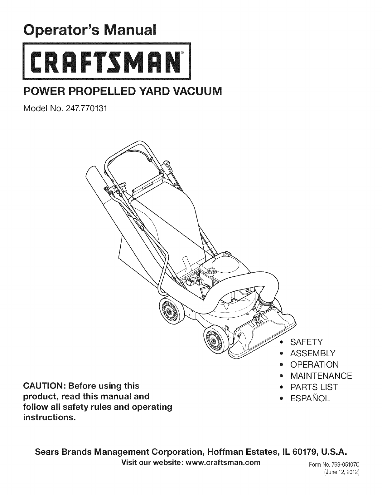
Operator's Manual
CRRFr MRN
POWER PROPELLED YARD VACUUM
Model No. 247.770131
CAUTION" Before using this
product, read this manual and
follow all safety rules and operating
instructions.
Sears Brands Management Corporation, Hoffman Estates, IL 60179, U.S.A.
Visit our website: www.craftsman.com FormNo. 769-05107C
,, SAFETY
o ASSEMBLY
OPERATION
MAINTENANCE
PARTS LIST
o ESPANOL
(June 12,2012)
Page 2
Warranty Statement .................................. Page 2
Safe Operation Practices .......................... Page 3
Safety Labels ............................................ Page 7
Assembly .................................................. Page 8
Operation .................................................. Page 12
Service and Maintenance ......................... Page 16
Off-Season Storage .................................. Page 22
Trouble Shooting ....................................... Page 23
Parts List ................................................... Page 24
Repair Protection Agreement ................... Page 38
Espa_ol ..................................................... Page 39
Service Numbers ...................................... Back Cover
CRAFTSMAN TWO YEAR FULL WARRANTY
FORTWOYEAR(S)fromthe dateof purchase,thisproductiswarrantedagainstanydefectsinmaterialorworkmanship.A defectiveproductwill
receivefreerepairorreplacementif repairisunavailable.
Forwarrantycoveragedetailsto obtainfreerepairor replacement,visittheweb site:www.craftsman.com
ThiswarrantycoversONLYdefectsin materialandworkmanship.WarrantycoveragedoesNOTinclude:
• Expendableitemsthatcanwearout fromnormalusewithinthe warrantyperiod,suchas theblades, sparkplug,aircleaner,flail
screenand catcherbag.
• Productdamageresultingfromuserattemptsatproductmodificationor repairorcausedby productaccessories.
• Repairsnecessarybecauseof accidentor failuretooperateormaintaintheproductaccordingto all suppliedinstructions.
• Preventivemaintenance,or repairsnecessarydueto improperfuel mixture,contaminatedorstalefuel.
Thiswarrantyis voidifthis productis everusedwhileprovidingcommercialservicesorif rentedtoanotherperson.
Thiswarrantygivesyouspecificlegal rights,andyoumayalsohaveotherrightswhichvaryfromstateto state.
Sears Brands Management Corporation, Hoffman Estates, IL 60179
EngineSeries: 675
EngineOilType: SAE30
EngineOilCapacity: 18ounces
FuelCapacity: 1.5Quarts
SparkPlugGap: .020"
ModelNumber.................................................................
Serial Number.................................................................
Dateof Purchase .............................................................
Recordthe modelnumber,serialnumber
anddateof purchaseabove
©SearsBrands,LLC 2
Page 3
Thissymbolpointsout importantsafetyinstructionswhich,if not
followed,couldendangerthe personalsafetyand/orpropertyof
yourselfandothers. Readandfollowall instructionsin thismanual
beforeattemptingtooperatethismachine.Failuretocomplywith
theseinstructionsmayresultin personalinjury.Whenyou seethis
symbol,HEEDITSWARNING!
Thismachinewasbuiltto beoperatedaccordingto the safeopera-
tionpracticesinthismanual.As withany typeof powerequipment,
carelessnessorerroronthepartoftheoperatorcan resultin
seriousinjury.Thismachineis capableofamputatingfingers,hands,
toesandfeetandthrowingdebris.Failureto observethefollowing
safetyinstructionscouldresultin seriousinjuryordeath.
CALIFORNIA PROPOSITION 65
EngineExhaust,someof itsconstituents,andcertainvehicle
componentscontainoremitchemicalsknowntoStateof California
tocausecancerandbirthdefectsorotherreproductiveharm.
TRAINING
• Read,understand,andfollowall instructionson themachineand
in themanualbeforeattemptingto assembleandoperate.Keep
thismanualina safeplaceforfutureandregularreferenceandfor
orderingreplacementparts.
• ReadtheOperator'sManualand followallwarningsandsafety
instructions.Failuretodosocan resultin seriousinjuryto the
operatorand/orbystanders.Forquestionscall, 1-800-4MY-
HOME.
• Befamiliarwithall controlsandtheirproperoperation.Knowhow
tostopthemachineanddisengagethemquickly.
• Neverallowchildrenunder16yearsofagetooperatethis
machine.Children16andovershouldreadandunderstandthe
instructionsandsafeoperationpracticesin thismanualandon
themachineandbe trainedandsupervisedbyanadult.
• Neverallowadultstooperatethismachinewithoutproper
instruction.
• Keepbystanders,pets,andchildrenatleast75feetfromthe
machinewhile it isin operation.Stopmachineifanyoneenters
thearea.
• Neverrunanengineindoorsorina poorlyventilatedarea.Engine
exhaustcontainscarbonmonoxide,anodorlessanddeadlygas.
• Do not puthandsandfeetnearrotatingpartsor inthe feeding
chambersanddischargeopening.Contactwiththe rotating
impellercanamputatefingers,hands,andfeet.
• Neverattemptto unclogeitherthe feedintakeordischarge
opening,removeor emptybag,or inspectandrepairthe machine
whilethe engineisrunning.Shuttheengineoff andwaituntilall
movingpartshavecometo a completestop.Disconnectthe spark
plugwireandgroundit againstthe engine.
Your Responsibility--Restrictthe useofthispowermachineto
personswhoread,understandandfollowthewarningsand instruc-
tionsin thismanualandon the machine.
SAVETHESEINSTRUCTIONS!
PREPARATION
• Thoroughlyinspecttheareawherethe equipmentistobeused.
Removeall rocks,bottles,cans,or otherforeignobjectswhich
couldbepickedupor thrownandcausepersonalinjuryor
damageto themachine.
• Alwayswearsafetyglassesorsafetygogglesduringoperation
andwhileperformingan adjustmentorrepair,to protectyour
eyes.Thrownobjectswhichricochetcancauseseriousinjuryto
theeyes.
• Wearsturdy,rough-soledworkshoesandclose-fittingslacksand
shirts.Loosefittingclothesorjewelrycanbecaughtin movable
parts.Neveroperatethismachineinbarefeetorsandals.Wear
leatherworkgloveswhenfeedingmaterialinthe chipperchute.
• Beforestarting,checkallboltsandscrewsforpropertightnessto
besurethe machineis insafeworkingcondition.Also,visually
inspectmachineforany damageatfrequentintervals.
• Maintainorreplacesafetyandinstructionslabels,asnecessary.
3
Page 4
SafeHandling of Gasoline:
Toavoidpersonalinjuryor propertydamageuseextremecarein
handlinggasoline.Gasolineisextremelyflammableandthe vaporsare
explosive.Seriouspersonalinjurycanoccurwhengasolineisspilled
onyourselforyourclotheswhichcanignite.Washyourskinand
changeclothesimmediately.
• Useonlyan approvedgasolinecontainer.
• Neverfill containersinsidea vehicleor ona truckor trailerbed
witha plasticliner.Alwaysplacecontainersonthegroundaway
fromyourvehiclebeforefilling.
• Whenpractical,removegas-poweredequipmentfromthetruck
ortrailerand refuelitontheground.Ifthisisnotpossible,then
refuelsuchequipmentona trailerwitha portablecontainer,rather
thanfroma gasolinedispensernozzle.
• Keepthe nozzleincontactwiththerimofthefueltankor
containeropeningat alltimes untilfuelingis complete.Donotuse
a nozzlelock-opendevice.
• Extinguishallcigarettes,cigars,pipesandothersourcesof
ignition.
• Neverfuel machineindoors.
• Neverremovegascaporaddfuelwhiletheengineishotor run-
ning.Allowenginetocoolat leasttwo minutesbeforerefueling.
• Neveroverfillfueltank. Fill tankto nomorethan1/2inchbelow
bottomoffillernecktoallowspacefor fuelexpansion.
• Replacegasolinecapandtightensecurely.
• Ifgasolineisspilled,wipeitoff theengineandequipment.Move
unitto anotherarea.Wait5 minutesbeforestartingtheengine.
• To reducefirehazards,keepmachinefreeofgrass,leaves,or
otherdebrisbuild-up.Cleanupoil orfuelspillageand removeany
fuelsoakeddebris.
• Neverstorethe machineorfuel containerinsidewherethereis an
openflame,sparkor pilotlightason awaterheater,spaceheater,
furnace,clothesdryer orothergasappliances.
OPERATION
• Do not puthandsandfeetnearrotatingpartsor in thefeeding
chambersanddischargeopening.Contactwiththe rotating
impellercanamputatefingers,hands,andfeet.
• Beforestartingthe machine,makesurethe chipperchute,feed
intake,andcuttingchamberare emptyandfreeofall debris.
• Thoroughlyinspectall materialtobe shreddedandremoveany
metal,rocks,bottles,cans,or otherforeignobjectswhichcould
causepersonalinjuryor damagetothe machine.
• Ifthe impellerstrikesa foreignobjector ifyourmachineshould
startmakinganunusualnoiseorvibration,immediatelyshut
theengineoff. Allowtheimpellertocometoa completestop.
Disconnectthesparkplugwire,grounditagainstthe engineand
performthefollowingsteps:
a. Inspectfor damage.
b. Repairorreplaceanydamagedparts.
c. Checkforanyloose partsandtightento assurecontinued
safeoperation.
• Donotallowanaccumulationof processedmaterialto buildupin
thedischargearea.Thiscanpreventproperdischargeandresult
inkickbackof materialthroughthe feedopening.
• Donotattempttoshredorchipmateriallargerthanspecified
on themachineor inthis manual.Personalinjuryor machine
damagecouldresult.
• Neverattempttounclogeitherthefeedintakeor discharge
openingwhilethe engineis running.Shuttheengineoff,waituntil
all movingpartshavestopped,disconnectthe sparkplugwireand
grounditagainsttheenginebeforeclearingdebris.
• Neveroperatewithoutvacuumbaganddischargechuteproperly
attachedtothe machine.Neveremptyor changevacuumbag
whilethe engineisrunning.Vacuumbagmustbekeptclosedat
all timesduringoperation.
• Neveroperatewithouteitherthe inletnozzleor optionalhose
attachment(ifapplicable)properlyattachedtothemachine.
Neverattemptto attachor changeeitherattachmentwhilethe
engineisrunning.
• Keepallguards,deflectorsandsafetydevicesin placeand
operatingproperly.
• Keepyourfaceandbodybackandtothesideofthechipper
chutewhilefeedingmaterialintothemachineto avoidaccidental
kickbackinjuries.
• Neveroperatethis machinewithoutgoodvisibilityorlight.Always
be sureofyourfootingand keepa firmholdon thehandles.
• Donotoperatethismachineona paved,gravelornon-level
surface.
• Donotoperatethismachinewhileundertheinfluenceof alcohol
or drugs.
• Mufflerandenginebecomehotandcancausea burn.Do not
touch.
• Neverpickuporcarrymachinewhiletheengineis running.
• Ifsituationsoccurwhichare notcoveredinthis manual,use care
andgoodjudgement.ContactCustomerSupportforassistance
andthenameof thenearestservicedealer.
4
Page 5
MAINTENANCE & STORAGE
• Nevertamperwithsafetydevices.Checktheirproperoperation
regularly.
• Checkboltsand screwsforpropertightnessatfrequentintervals
tokeepthemachinein safeworkingcondition.Also,visually
inspectmachineforanydamageand repair,ifneeded.
Beforecleaning,repairing,or inspecting,stopthe engineand
makecertaintheimpellerand allmovingpartshavestopped.
Disconnectthesparkplugwireandgrounditagainstthe engine
topreventunintendedstarting.
Donotchangetheenginegovernorsettingsor overspeedthe
engine.Thegovernorcontrolsthe maximumsafeoperatingspeed
ofthe engine.
Maintainor replacesafetyandinstructionlabels,asnecessary.
Followthismanualforsafeloading,unloading,transporting,and
storageof thismachine.
Neverstorethemachineorfuelcontainerinsidewherethereisan
openflame,sparkorpilotlightsuchasa waterheater,furnace,
clothesdryer,etc.
Allowmachinetocoolatleast5 minutesbeforestoring.
• Alwaysreferto the operator'smanualforproperinstructionson
off-seasonstorage.
• If thefuel tankhasto bedrained,dothisoutdoors.
• Observeproperdisposallawsand regulationsforgas,oil,etc.to
protecttheenvironment.
• AccordingtotheConsumerProductsSafetyCommission(CPSC)
andtheU.S.EnvironmentalProtectionAgency(EPA),thisproduct
hasan Average UsefulLifeofseven(7)years,or 60hoursof
operation.At theendoftheAverageUsefulLifehavethemachine
inspectedannuallybyan authorizedservicedealerto ensurethat
allmechanicalandsafetysystemsareworkingproperlyand not
wornexcessively.Failureto do socan resultinaccidents,injuries
ordeath.
DO NOT MODIFY ENGINE
Toavoidseriousinjuryordeath,donotmodifyenginein anyway.
Tamperingwiththegovernorsettingcanleadto a runawayengineand
causeitto operateatunsafespeeds.Nevertamperwithfactorysetting
ofenginegovernor.
NOTICE REGARDING EMISSIONS
EngineswhicharecertifiedtocomplywithCaliforniaandfederal
EPAemissionregulationsforSORE(SmallOffRoadEquipment)are
certifiedto operateonregularunleadedgasoline,and mayinclude
thefollowingemissioncontrolsystems:EngineModification(EM),
OxidizingCatalyst(OC),SecondaryAirInjection(SAI)and ThreeWay
Catalyst(TWO)if soequipped.
SPARK ARRESTOR
Thismachineis equippedwithan internalcombustionengineand
shouldnotbe usedonor nearanyunimprovedforest-covered,
brushcoveredor grass-coveredlandunlesstheengine'sexhaust
systemisequippedwitha sparkarrestormeetingapplicablelocal or
statelaws(if any).
Ifa sparkarrestoris used,it shouldbe maintainedin effectiveworking
orderbytheoperator.IntheStateofCaliforniathe aboveis required
bylaw (Section4442of theCaliforniaPublicResourcesCode).Other
statesmayhavesimilarlaws. Federallawsapplyonfederallands.
A sparkarrestorforthemuffleris availablethroughyournearestSears
PartsandRepairServiceCenter.
Page 6
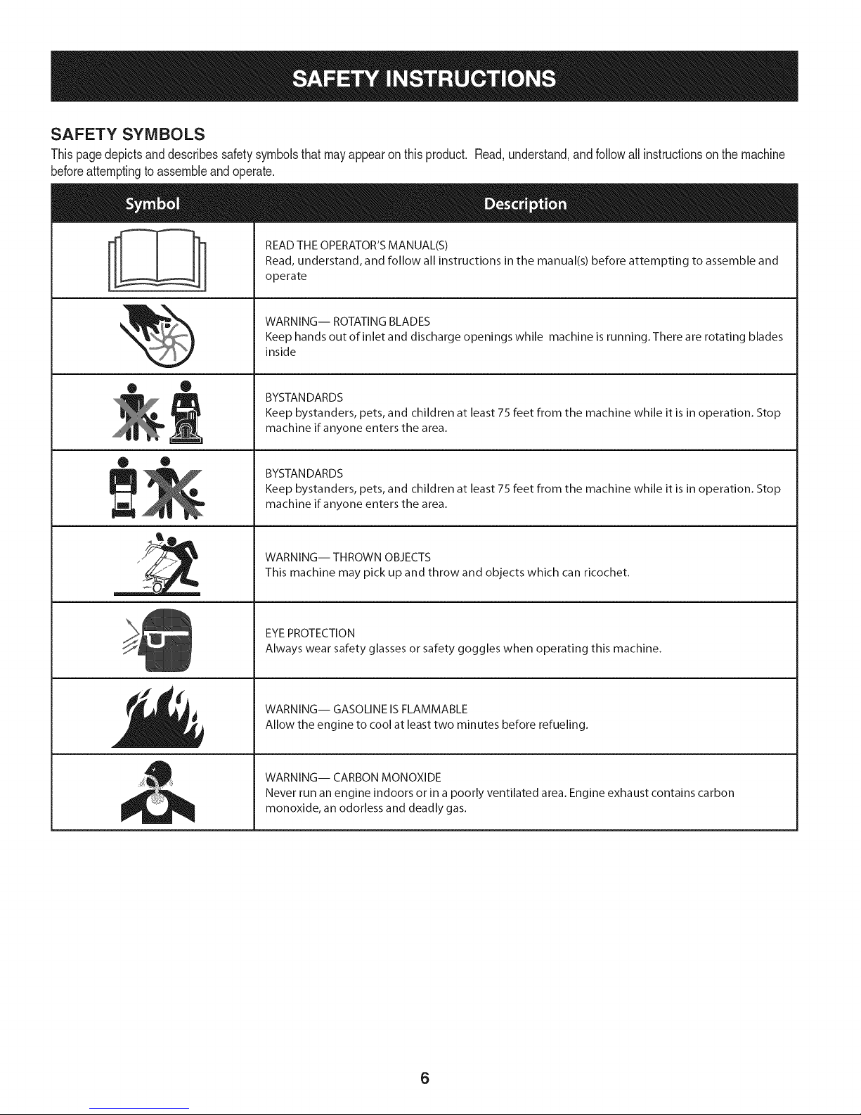
SAFETY SYMBOLS
Thispagedepictsanddescribessafetysymbolsthatmayappearonthisproduct. Read,understand,andfollowall instructionson themachine
beforeattemptingtoassembleandoperate.
READ THE OPERATOR'S MANUAL(S)
i
i
Read, understand, and follow all instructions in the manual(s) before attempting to assemble and
operate
WARNING-- ROTATING BLADES
Keep hands out of inlet and discharge openings while machine is running. There are rotating blades
inside
• ®
® •
llm
il
BYSTANDARDS
Keep bystanders, pets, and children at least 75 feet from the machine while it is in operation. Stop
machine if anyone enters the area.
BYSTANDARDS
Keep bystanders, pets, and children at least 75 feet from the machine while it is in operation. Stop
machine if anyone enters the area.
WARNING-- THROWN OBJECTS
This machine may pick up and throw and objects which can ricochet.
EYEPROTECTION
Always wear safety glasses or safety goggles when operating this machine.
WARNING-- GASOLINE IS FLAMMABLE
Allow the engine to cool at least two minutes before refueling.
WARNING-- CARBON MONOXIDE
Never run an engine indoors or in a poorly ventilated area. Engine exhaust contains carbon
monoxide, an odorless and deadly gas.
6
Page 7

Thispageleftintentionallyblank.
7
Page 8
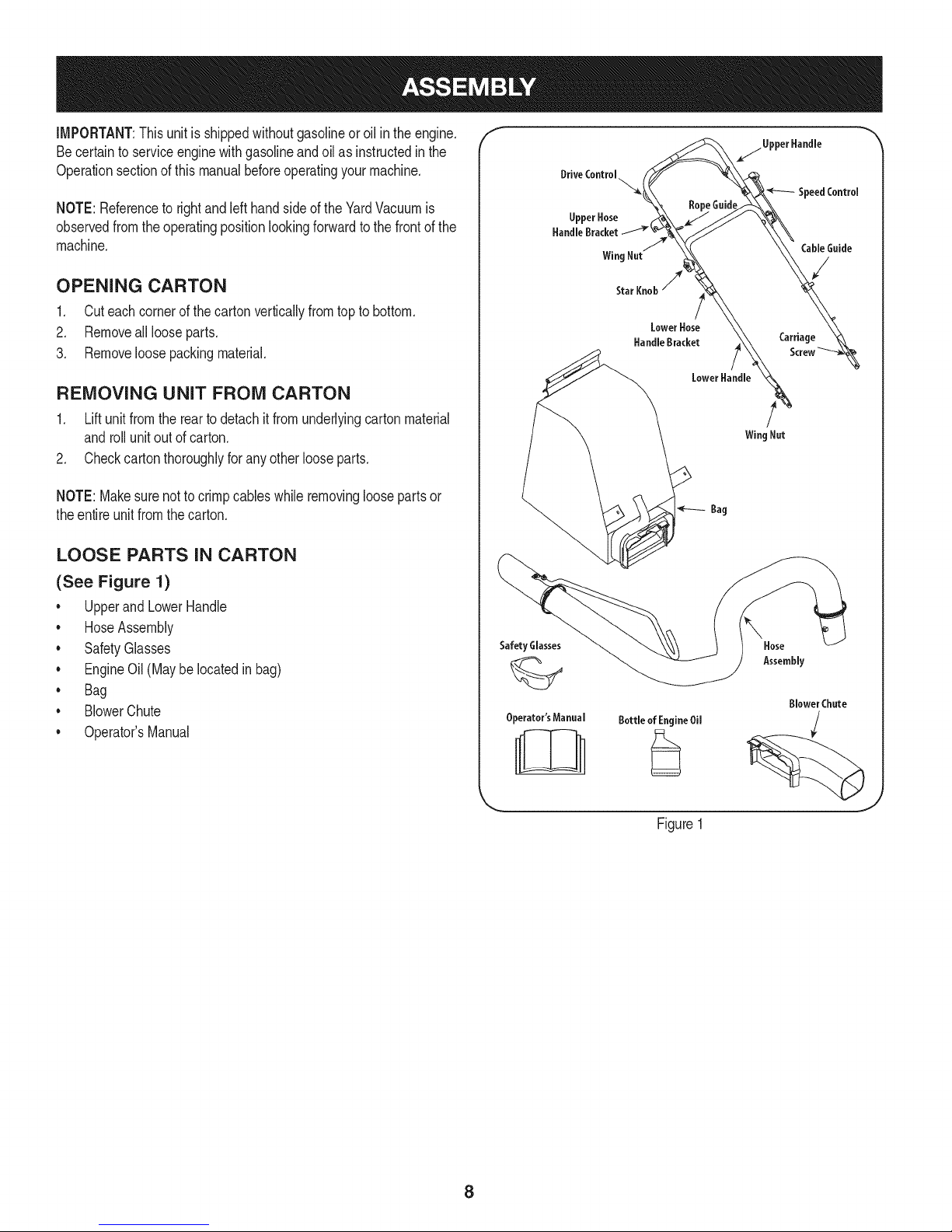
IMPORTANT:Thisunit isshippedwithoutgasolineoroil intheengine.
Becertaintoserviceenginewithgasolineandoilas instructedinthe
Operationsectionof this manualbeforeoperatingyourmachine.
NOTE:Referenceto rightand lefthandsideoftheYardVacuumis
observedfromthe operatingpositionlookingforwardtothefrontof the
machine.
OPENING CARTON
1. Cuteachcornerofthecartonverticallyfromtopto bottom.
2. Removeall looseparts.
3. Removeloosepackingmaterial.
REMOVING UNIT FROM CARTON
1. Liftunitfromthereartodetachitfromunderlyingcartonmaterial
androllunitoutofcarton.
2. Checkcartonthoroughlyforanyotherlooseparts.
NOTE:Makesurenottocrimpcableswhileremovingloosepartsor
theentire unitfromthecarton.
LOOSE PARTS IN CARTON
f
(See Figure 1)
* UpperandLowerHandle
. HoseAssembly
* SafetyGlasses
. EngineOil(Maybelocatedinbag)
* Bag
. BlowerChute
* Operator'sManual
Safety Glasses
Operator'sManual
\
Hose
Assembly
BlowerChute
Bottle of EngineOil
J
Figure1
8
Page 9
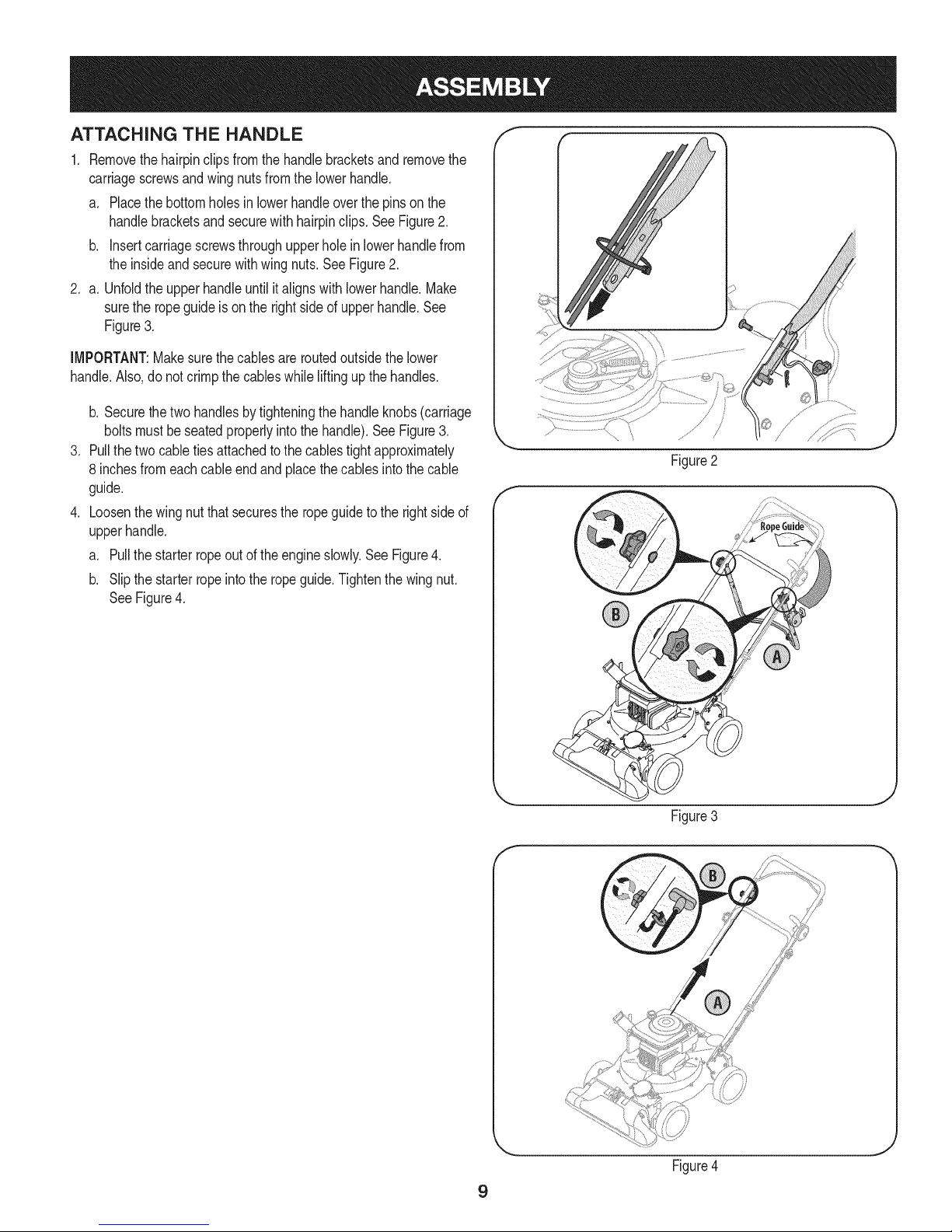
ATTACHING THE HANDLE
1. Removethehairpinclipsfromthehandlebracketsand removethe
carriagescrewsandwingnutsfromthelowerhandle.
a. Placethebottomholesinlowerhandleoverthepinson the
handlebracketsand securewith hairpinclips. SeeFigure2.
b. insertcarriagescrewsthroughupperholeinlowerhandlefrom
theinsideandsecurewithwingnuts.SeeFigure2.
2. a. Unfoldthe upperhandleuntilitalignswithlowerhandle.Make
surethe ropeguideis onthe rightsideof upperhandle.See
Figure3.
IMPORTANT:Makesurethecablesareroutedoutsidethelower
handle.Also,donot crimpthe cableswhileliftingupthe handles.
b. Securethetwo handlesbytighteningthehandleknobs(carriage
boltsmustbeseatedproperlyintothehandle).SeeFigure3.
.
Pullthetwo cabletiesattachedtothecablestightapproximately
8 inchesfromeachcableendandplacethe cablesintothecable
guide.
.
Loosenthewingnut thatsecurestheropeguidetothe rightsideof
upperhandle.
a. Pullthe starterropeoutof the engineslowly.SeeFigure4.
b. Slipthe starterropeintothe ropeguide.Tightenthewingnut.
SeeFigure4.
Figure2
J
Figure3
J
Figure4
9
Page 10
f
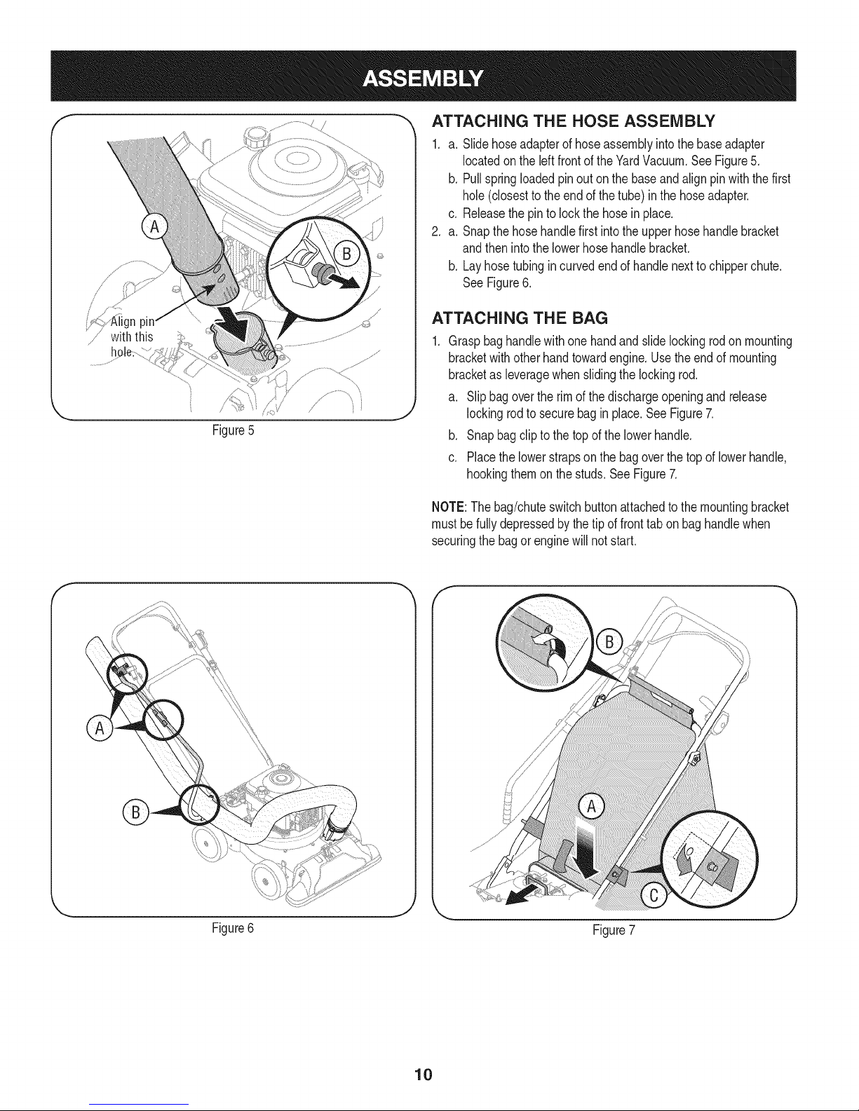
_, ATTACHING THE HOSE ASSEMBLY
1. a. Slidehoseadapterof hoseassemblyintothebaseadapter
locatedon theleftfrontoftheYardVacuum.SeeFigure5.
b. Pullspringloadedpinouton thebaseandalignpinwiththefirst
hole(closestto the endof the tube)inthehoseadapter.
c. Releasethe pinto lockthe hosein place.
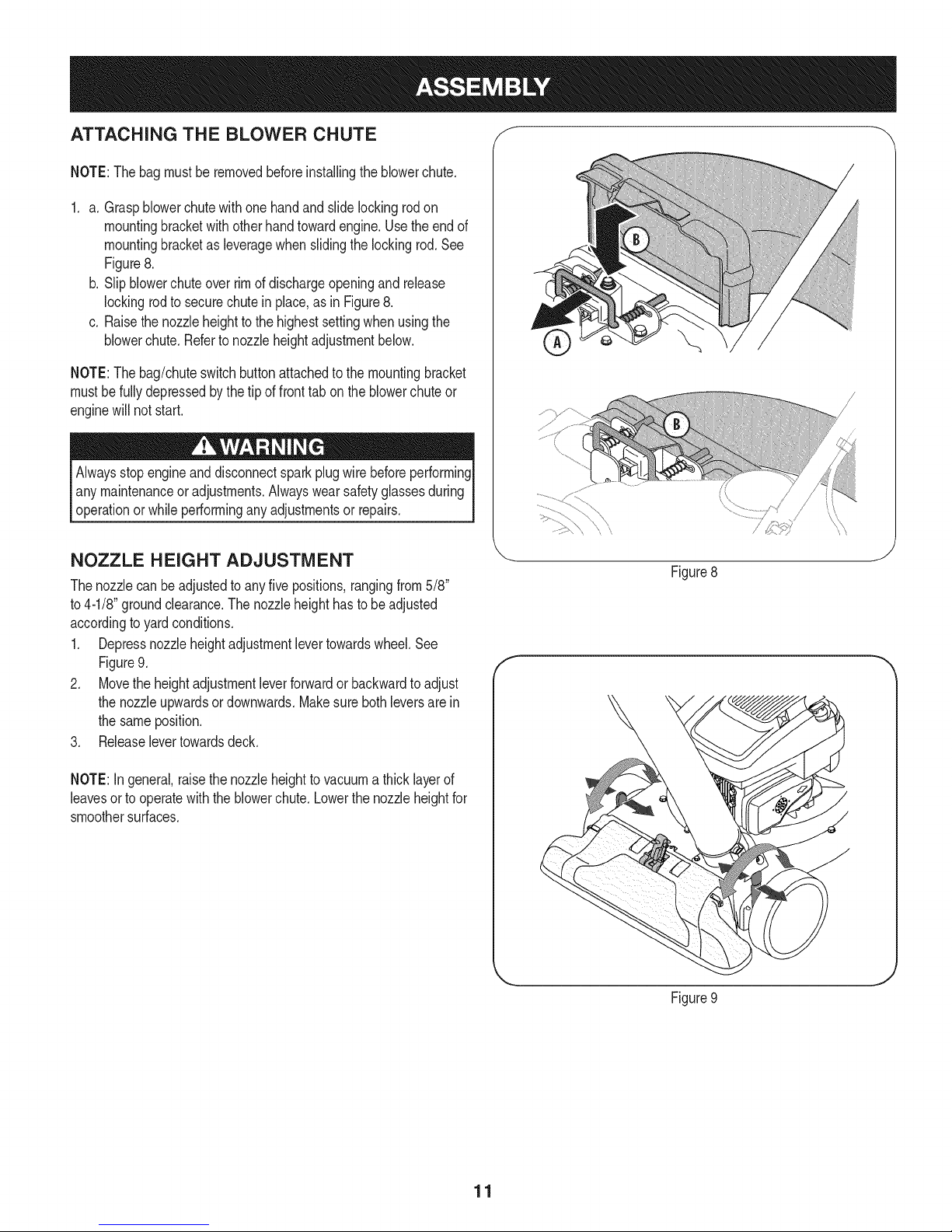
2. a. Snapthehosehandlefirstintothe upperhose handlebracket
andthenintothe lowerhosehandlebracket.
b. Layhosetubingincurvedendofhandlenexttochipperchute.
SeeFigure6.
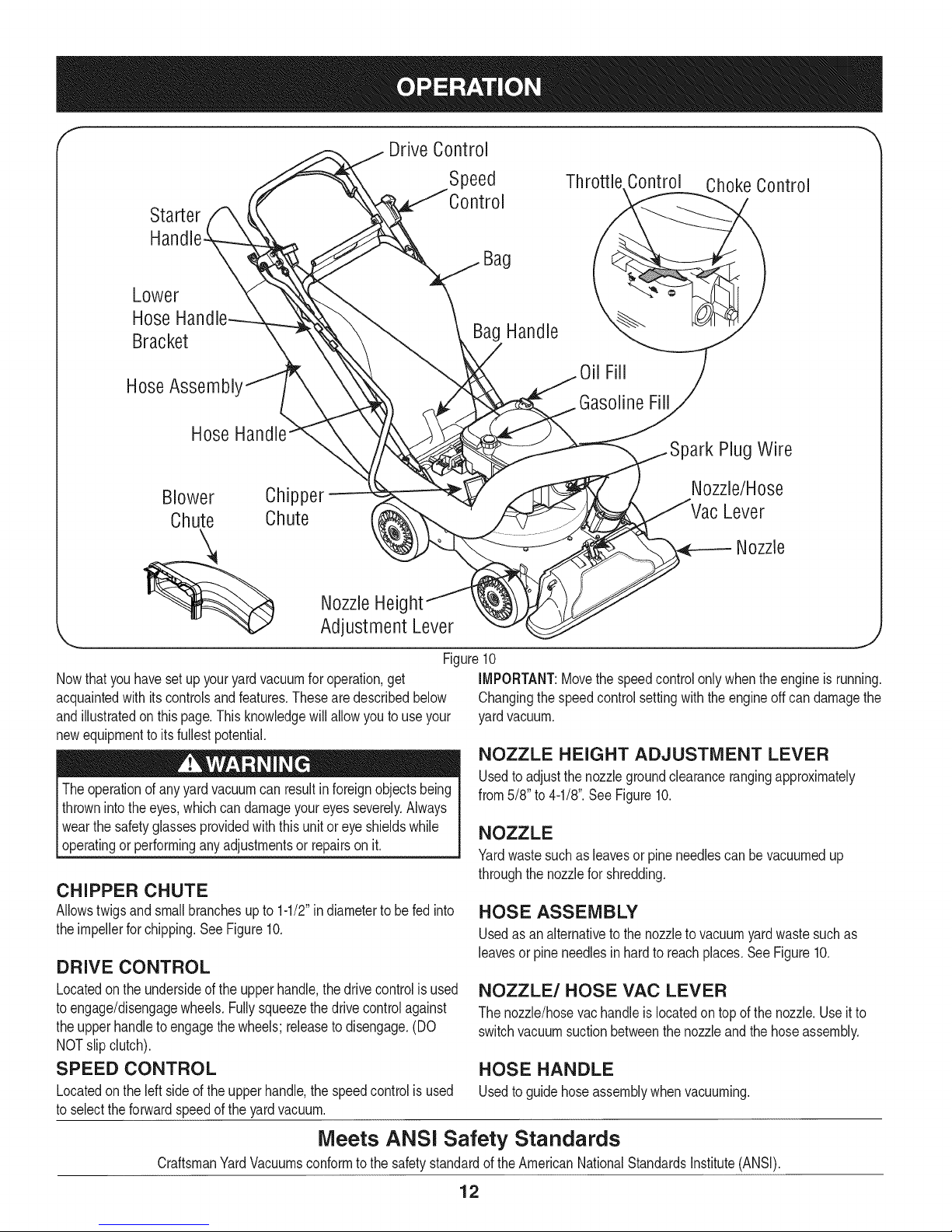
ATTACHING THE BAG
Graspbaghandlewithonehandandslidelockingrodonmounting
bracketwithotherhandtowardengine.Usetheendof mounting
bracketas leveragewhenslidingthe lockingrod.
a. Slipbagovertherimofthe dischargeopeningandrelease
lockingrodtosecurebagin place.SeeFigure7.
Figure5
b. Snapbagclipto thetopof the lowerhandle.
c. Placethelowerstrapson thebagoverthetopof lowerhandle,
hookingthemon thestuds.SeeFigure7.
NOTE:The bag/chuteswitchbuttonattachedtothemountingbracket
mustbefullydepressedby thetipof fronttabon baghandlewhen
securingthebagorenginewillnotstart.
Figure6
Figure7
10
Page 11
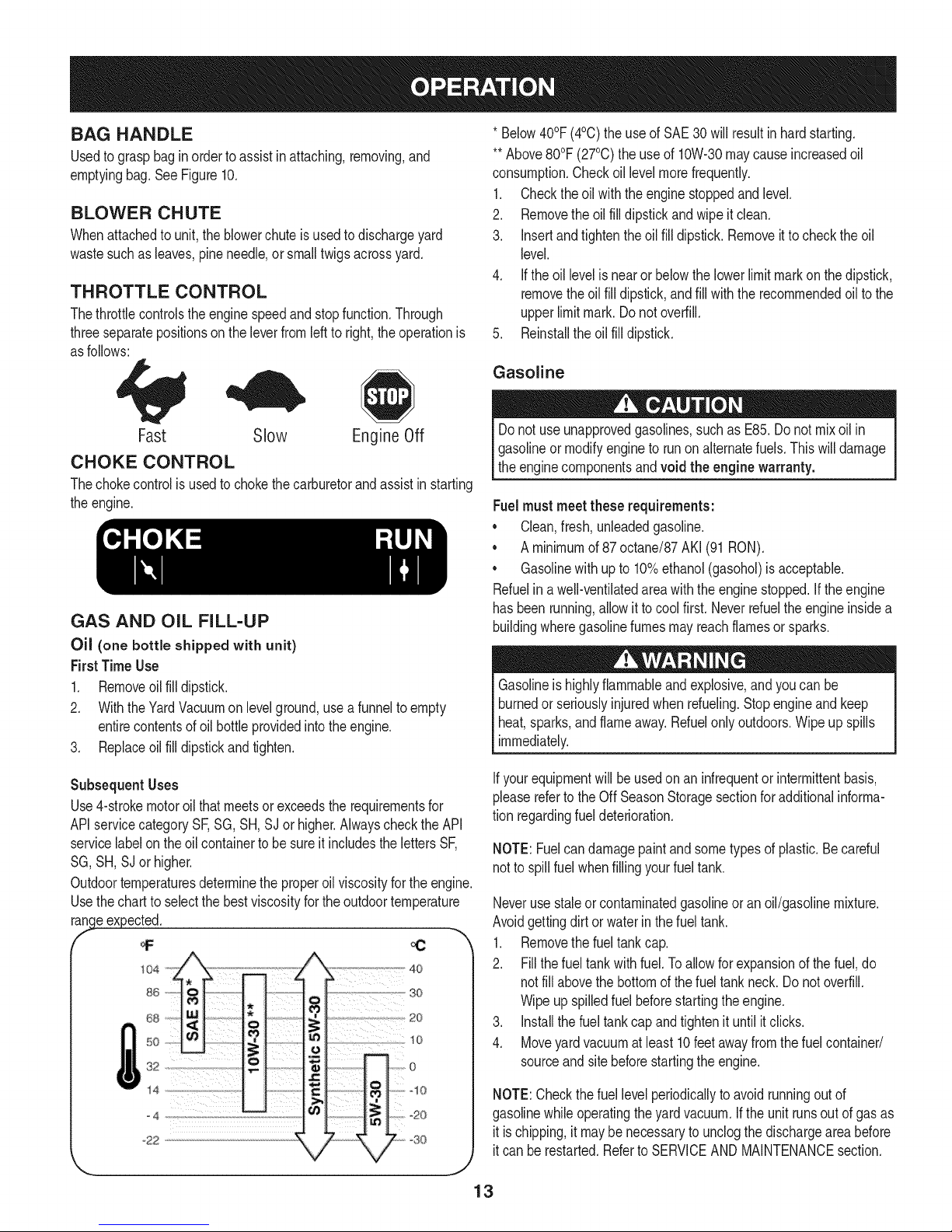
ATTACHING THE BLOWER CHUTE f
NOTE:Thebagmustberemovedbeforeinstallingtheblowerchute.
1. a. Graspblowerchutewithone handandslidelockingrodon
mountingbracketwithotherhandtowardengine.Usethe endof
mountingbracketas leveragewhenslidingthelockingrod.See
Figure8.
b. Slipblowerchuteoverrimof dischargeopeningandrelease
lockingrodto securechutein place,asin Figure8.
c. Raisethe nozzleheighttothe highestsettingwhenusingthe
blowerchute.Refertonozzleheightadjustmentbelow.
NOTE:Thebag/chuteswitchbuttonattachedtothe mountingbracket
mustbefullydepressedbythe tipoffronttabontheblowerchuteor
enginewillnot start.
Alwaysstopengineanddisconnectsparkplugwire beforeperforming
anymaintenanceoradjustments.Alwayswearsafetyglassesduring
operationorwhileperforminganyadjustmentsor repairs.
NOZZLE HEIGHT ADJUSTMENT
Thenozzlecan beadjustedto anyfive positions,rangingfrom5/8"
to4-1/8"groundclearance.Thenozzleheighthastobe adjusted
accordingto yardconditions.
1. Depressnozzleheightadjustmentlevertowardswheel.See
Figure9.
2. Movetheheightadjustmentleverforwardor backwardto adjust
thenozzleupwardsordownwards.Makesurebothleversarein
thesameposition.
3. Releaselevertowardsdeck.
\\
J
Figure8
f
NOTE:In general,raisethenozzleheighttovacuuma thicklayerof
leavesortooperatewiththeblowerchute.Lowerthenozzleheightfor
smoothersurfaces.
J
Figure9
11
Page 12
f
Drive Control
Speed Thr( Control Choke Control
Starter
Bag
Lower
Hose
Bracket
Bag Handle
HoseAssembl'
Hose
Blower Chipper
Chute Chute
NozzleHeig
Adjustment Lever
Figure10
Nowthat youhavesetup youryardvacuumforoperation,get
acquaintedwith itscontrolsandfeatures.Thesearedescribedbelow
andillustratedon thispage.Thisknowledgewill allowyoutouseyour
newequipmenttoits fullestpotential.
Theoperationofanyyardvacuumcanresultinforeignobjectsbeing
thrownintothe eyes,whichcandamageyoureyesseverely.Always
Iwearthesafetyglassesprovidedwiththisunitoreyeshieldswhile
[operatingor performinganyadjustmentsor repairsonit.
CHIPPER CHUTE
Allowstwigsandsmallbranchesupto 1-1/2"indiametertobe fedinto
theimpellerforchipping.SeeFigure10.
DRIVE CONTROL
Locatedon theundersideof the upperhandle,thedrivecontrolisused
toengage/disengagewheels.Fullysqueezethedrivecontrolagainst
theupperhandleto engagethe wheels;releasetodisengage.(DO
NOTslipclutch).
SPEED CONTROL
Locatedon theleftsideof the upperhandle,thespeedcontrolis used
toselecttheforwardspeedoftheyardvacuum.
Oil Fill
GasolineFill
)ark PlugWire
Nozzle/Hose
Lever
Nozzle
iMPORTANT:Movethe speedcontrolonlywhentheengineisrunning.
Changingthespeedcontrolsettingwiththeengineoffcandamagethe
yardvacuum.
NOZZLE HEIGHT ADJUSTMENT LEVER
Usedtoadjustthe nozzlegroundclearancerangingapproximately
from5/8"to 4-1/8".See Figure10.
NOZZLE
Yardwastesuchas leavesorpineneedlescanbevacuumedup
throughthe nozzleforshredding.
HOSE ASSEMBLY
Usedasanalternativeto thenozzleto vacuumyardwastesuchas
leavesor pineneedlesin hardto reachplaces.SeeFigure10.
NOZZLE/HOSE VAC LEVER
Thenozzle/hosevachandleis locatedon topofthenozzle.Useit to
switchvacuumsuctionbetweenthenozzleandthe hoseassembly.
HOSE HANDLE
Usedtoguidehoseassemblywhenvacuuming.
Meets ANSI Safety Standards
CraftsmanYardVacuumsconformto thesafetystandardof the AmericanNationalStandardsinstitute(ANSi).
12
Page 13
BAG HANDLE
Usedtograsp baginorderto assistinattaching,removing,and
emptyingbag.SeeFigure10.
BLOWER CHUTE
Whenattachedtounit,theblowerchuteisusedtodischargeyard
wastesuchas leaves,pineneedle,orsmalltwigsacrossyard.
THROTTLE CONTROL
Thethrottlecontrolstheenginespeedandstopfunction.Through
threeseparatepositionson theleverfromleftto right,theoperationis
asfollows:
*Below40°F(4°C)theuseof SAE30will resultinhardstarting.
**Above80°F(27°C)the useof 10%30 maycauseincreasedoil
consumption.Checkoillevelmorefrequently.
1. Checktheoilwiththeenginestoppedandlevel.
2. Removetheoilfilldipstickandwipeitclean.
3. Insertandtightentheoil fill dipstick.Removeitto checktheoil
level.
4. Iftheoil levelisnearor belowthelowerlimitmarkonthedipstick,
removethe oilfill dipstick,andfillwiththerecommendedoilto the
upperlimitmark.Do notoverfill.
5. Reinstalltheoil filldipstick.
Gasoline
Fast Slow EngineOff
CHOKE CONTROL
Thechokecontrolis usedtochokethecarburetorandassistinstarting
theengine.
GAS AND OiL FILL-UP
Oil (one bottle shipped with unit)
First TimeUse
1. Removeoilfilldipstick.
2. WiththeYardVacuumon levelground,usea funnelto empty
entirecontentsofoil bottleprovidedintotheengine.
3. Replaceoilfilldipstickandtighten.
Subsequent Uses
Use4-strokemotoroilthatmeetsorexceedstherequirementsfor
APIservicecategorySF,SG,SH,SJor higher.Alwayscheckthe API
servicelabelon theoilcontainerto besureit includesthelettersSF,
SG,SH, SJor higher.
Outdoortemperaturesdeterminetheproperoilviscosityfortheengine.
Usethechartto selectthe bestviscosityfortheoutdoortemperature
r_..ge #xpected.
68 20
so _o
s2,,
14 C _ '"t'x '_10
=_[_ 1._ [ o
, °°I,
Donot useunapprovedgasolines,suchas E85.Donotmixoil in
Igasolineor modifyenginetorunonalternatefuels.Thiswilldamage
[the enginecomponentsandvoid the enginewarranty.
Fuelmust meetthese requirements:
• Clean,fresh,unleadedgasoline.
• A minimumof87octane/87AKI(91RON).
• Gasolinewithup to 10%ethanol(gasohol)isacceptable.
Refuelina well-ventilatedareawiththeenginestopped.Iftheengine
hasbeenrunning,allowittocoolfirst.Neverrefueltheengineinsidea
buildingwheregasolinefumesmayreachflamesor sparks.
Gasolineishighlyflammableand explosive,andyoucanbe
burnedor seriouslyinjuredwhenrdueling.Stopengineandkeep
heat,sparks,andflameaway.Refuelonlyoutdoors.Wipeup spills
immediately.
Ifyourequipmentwillbe usedon an infrequentor intermittentbasis,
pleaserefertothe Off SeasonStoragesectionforadditionalinforma-
tionregardingfueldeterioration.
NOTE:Fuelcandamagepaintandsometypesof plastic.Becareful
notto spillfuelwhenfillingyourfuel tank.
Neverusestaleorcontaminatedgasolineoranoil/gasolinemixture.
Avoidgettingdirt or waterinthefueltank.
1. Removethefueltankcap.
2. Fillthe fueltankwithfuel.Toallowforexpansionofthe fuel,do
notfill abovethebottomofthefueltank neck.Donotoverfill.
Wipeupspilledfuelbeforestartingtheengine.
3. Installthefueltankcap andtightenit untilitclicks.
4. Moveyard vacuumatleast10feetawayfromthefuelcontainer/
sourceand sitebeforestartingtheengine.
NOTE:Checkthefuellevelperiodicallytoavoidrunningoutof
gasolinewhileoperatingtheyardvacuum.Ifthe unit runsoutof gas as
itis chipping,it maybenecessaryto unclogthedischargeareabefore
itcan berestarted.Referto SERVICEAND MAINTENANCEsection.
13
Page 14
TopView
TO START ENGINE
BagYC_hutei/
Switch:Wire /
/
iiii FrontTab i i
/
Figure11
ChokeControl
Besurenooneotherthan theoperatoris standingnearthe yard
vaccumwhilestartingengineoroperatingvacuum.Neverrunengine
indoorsorin enclosed,poorlyventilatedareas.Engineexhaust
containscarbonmonoxide,an odorlessanddeadlygas.Keephands,
feet,hairand looseclothingawayfromany movingpartson engine
andyardvacuum.
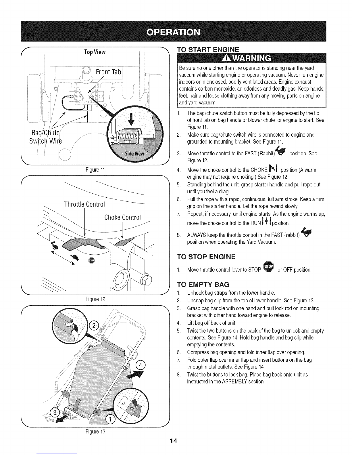
1. Thebag/chuteswitchbuttonmustbefullydepressedbythe tip
offronttabon baghandleorblowerchuteforengineto start.See
Figure11.
2. Makesurebag/chuteswitchwireis connectedtoengineand
groundedtomountingbracket.SeeFigure11.
3. Movethrottlecontroltothe FAST(Rabbit)4_ position.See
Figure12.
4. Movethechokecontrolto the CHOKE_,1 position(Awarm
enginemaynotrequirechoking.)SeeFigure12.
5. Standingbehindtheunit,graspstarterhandleandpull ropeout
untilyoufeeladrag.
6. Pulltheropewitha rapid,continuous,fullarmstroke.Keepa firm
gripon the starterhandle.Letthe roperewindslowly.
7. Repeat,ifnecessary,untilenginestarts.Astheenginewarmsup,
movethechokecontroltothe RUNI _'I position.
8. ALWAYSkeepthethrottlecontrolinthe FAST(rabbit)
positionwhenoperatingtheYardVacuum.
TO STOP ENGINE
1. Movethrottlecontrolleverto STOP or OFFposition.
TO EMPTY BAG
1. Unhookbagstrapsfromthe lowerhandle.
Figure12
f
;/
2. Unsnapbagclip fromthetopoflowerhandle.See Figure13.
3. Graspbaghandlewithonehandandpulllock rodonmounting
bracketwithotherhandtowardengineto release.
4. Liftbagoffbackof unit.
5. Twistthetwobuttonsonthe backofthe bagto unlockandempty
contents.SeeFigure14.Holdbaghandleandbagclip while
emptyingthecontents.
6. Compressbagopeningandfoldinnerflapoveropening.
7. Foldouterflapoverinnerflapandinsertbuttonsonthebag
throughmetaloutlets.SeeFigure14.
8. Twistthebuttonsto lockbag.Placebagbackonto unitas
instructedintheASSEMBLYsection.
Figure13
Page 15
TO REMOVE BLOWER CHUTE
1. Graspblowerchutewithonehandandpull lockrodonmounting
bracketwithotherhandtowardengineto release.Referto Figure
8 inthe ASSEMBLYsection.
2. Removeblowerchutefromoverthe rimofthedischargeopening.
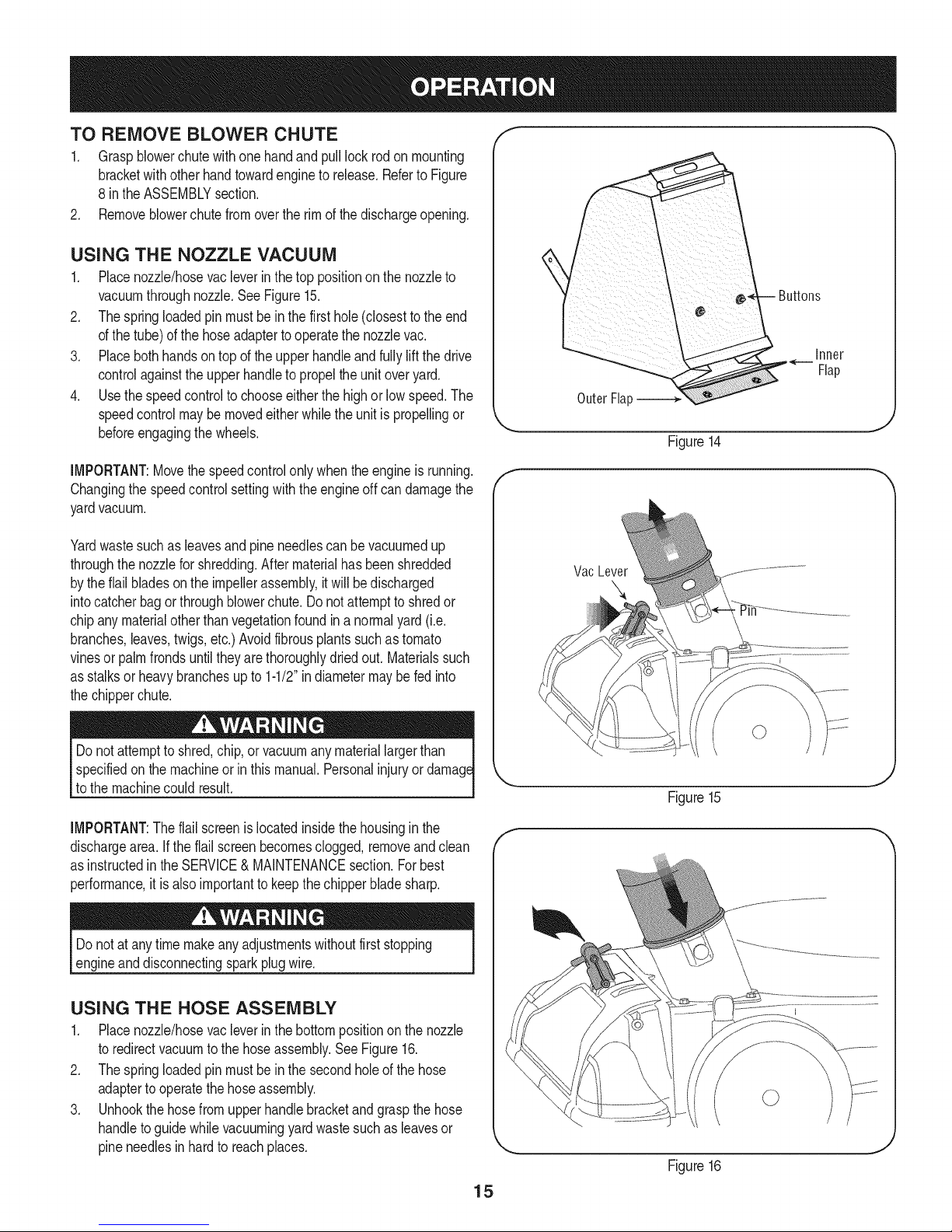
USING THE NOZZLE VACUUM
1. Placenozzle/hosevacleverinthetop positiononthe nozzleto
vacuumthroughnozzle.SeeFigure15.
2. Thespringloadedpinmustbein the firsthole(closesttotheend
ofthe tube)ofthehoseadaptertooperatethe nozzlevac.
3. Placebothhandsontopof the upperhandleandfullyliftthedrive
controlagainsttheupperhandleto propelthe unitoveryard.
4. Usethespeedcontrolto chooseeitherthe highorlowspeed.The
speedcontrolmaybemovedeitherwhiletheunitis propellingor
beforeengagingthewheels.
IMPORTANT:Movethe speedcontrolonlywhentheengineis running.
Changingthespeedcontrolsettingwiththeengineoff candamagethe
yardvacuum.
Yardwastesuchas leavesandpineneedlescanbevacuumedup
throughthenozzleforshredding.Aftermaterialhasbeenshredded
bytheflailbladesontheimpellerassembly,itwillbedischarged
intocatcherbagorthroughblowerchute.Donotattempttoshredor
chipany materialotherthanvegetationfoundin a normalyard(i.e.
branches,leaves,twigs,etc.)Avoidfibrousplantssuchastomato
vinesor palmfrondsuntiltheyare thoroughlydriedout. Materialssuch
asstalksor heavybranchesupto 1-1/2"indiametermaybe fedinto
thechipperchute.
Inner
Flap
Outer Flap
Figure14
Vac Lever
specifiedonthe machineorin thismanual.Personalinjuryor
to themachinecouldresult.
IMPORTANT:Theflailscreenis locatedinsidethehousinginthe
dischargearea. Ifthe flail screenbecomesclogged,removeandclean
asinstructedintheSERVICE&MAINTENANCEsection.Forbest
performance,itis alsoimportanttokeepthechipperbladesharp.
Donotatanytimemakeanyadjustmentswithoutfirststopping
engineanddisconnectingsparkplugwire.
USING THE HOSE ASSEMBLY
1. Placenozzle/hosevacleverinthebottompositionon thenozzle
toredirectvacuumtothehoseassembly.SeeFigure16.
2. Thespringloadedpinmustbein the secondholeof thehose
adaptertooperatethehoseassembly.
3. Unhookthehosefromupperhandlebracketandgraspthe hose
handletoguidewhilevacuumingyardwastesuchas leavesor
pineneedlesinhardto reachplaces.
Figure15
F
Figure16
15
Page 16
MAINTENANCE SCHEDULE
Beforeperforminganytypeofmaintenance/service,disengageall
controlsandstoptheengine.Waituntilallmovingpartshavecometo
acompletestop.Disconnectsparkplugwireandgroundit toprevent
unintendedstarting.Alwayswearsafetyglassesduringoperationorwhile
performinganyadjustmentsorrepairs.
EachUse
1st5 hours
Annuallyor25hours
Annuallyor50hours
Annually
BeforeStorage
Cleanmoreoftenunderdustyconditionsor whenairbornedebrisis
.
Engineoillevel
2.
Looseormissinghardware
3.
Unitandengine.
1.
Engineoil
1.
Aircleaned-
2.
Controllinkages/pivotsandwheels
3.
Undersideof mowerdeck
1.
Engineoil
1.
Sparkplug
2.
AirCleaner
1.
Fuelsystem
Followthemaintenanceschedulegivenbelow.Thischartdescribes
serviceguidelinesonly.Usethe ServiceLogcolumnto keeptrackof
completedmaintenancetasks.To locate the nearest SearsService
Centeror to scheduleservice,simplycontactSearsat
1-800-4-MY-HOME®.
1. Check
2. Tightenor replace
3. Clean
1. Change
1. Clean
2. Lubewithlightoil
3. Clean
1. Change
1. Replace
2. Replace
1. Runengineuntilitstopsfromlackof
fuel,oraddstabilizertoa fulltankof
freshfuelpriortostorage.
_resent.Replaceaircleanerif verydirty.
Alwaysstopengineanddisconnectsparkplugwire beforeperforming
Ianymaintenanceoradjustments.Alwayswearsafetyglassesduring
_operationor whileperforminganyadjustmentsor repairs.
GENERAL RECOMMENDATIONS
• Alwaysobservesafetyruleswhenperforming
anymaintenance.
• Thewarrantyonthisyardvacuumdoesnotcoveritemsthat have
beensubjectedtooperatorabuseor negligence.To receivefull
valuefromwarranty,operatormustmaintaintheequipmentas
instructedhere.
• Someadjustmentswillhavetobe madeperiodicallytomaintain
yourunit properly.
• Periodicallycheckall fastenersand makesurethesearetight.
ENGINE MAINTENANCE
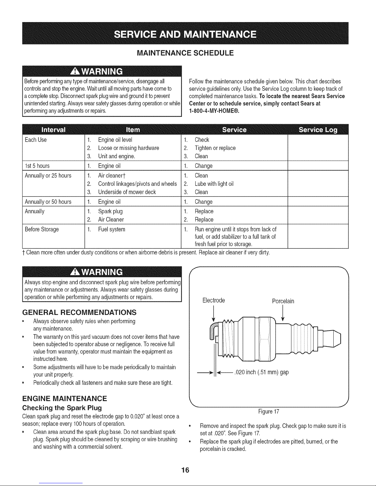
Checking the Spark Plug
Cleansparkplugandresettheelectrodegapto0.020"atleastonce a
season;replaceevery100hoursof operation.
Cleanareaaroundthe sparkplugbase.Do not sandblastspark
plug.Sparkplugshouldbecleanedbyscrapingorwirebrushing
andwashingwitha commercialsolvent.
f
Electrode
.020inch (.51 ram)gap
Removeandinspectthe sparkplug.Checkgaptomakesureit is
setat .020".SeeFigure17.
• Replacethesparkplugif electrodesare pitted,burned,orthe
porcelainiscracked.
Porcelain
Figure17
J
16
Page 17
Servicing the Air Cleaner
Theair cleanerpreventsdamagingdirt, dust,etc.,fromenteringthe
carburetorand beingforcedintothe engineandis importanttoengine
lifeandperformance.Theaircleanerconsistsofa pleatedfilter.Never
runtheenginewithoutanaircleanercompletelyassembled.
Cleantheair cleanerevery25hoursofoperationoroncea season.
Replacetheaircleanerannually.
Neverstartor runtheenginewiththeaircleanerassemblyortheair
filterremoved.
NOTE:Do notusepressurizedairor solventstocleanthe filter.Pres-
surizedair candamagethefilterandsolventswilldissolvethefilter.
1. Loosenthefastenerthatholdsthecoverandtilt plastichousing
coveron sideofenginedown.SeeFigure18.
2. Removeairfilterfromplastichousingcover.
3. Toloosendebris,gentlytapthefilterona hardsurface.Ifthefilter
isexcessivelydirty,replacewitha newfilter.
4. Insertcover'stabsinto slotsin bottomofbase.
5. Tiltcoverupinto placeandsecurewithfastener.
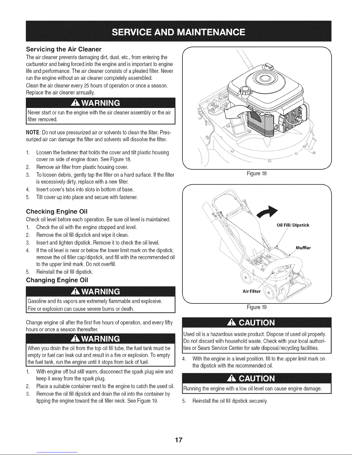
Checking Engine Oil
Checkoillevelbeforeeachoperation.Be sureoillevelismaintained.
1. Checktheoil withthe enginestoppedandlevel.
2. Removetheoil fill dipstickandwipe itclean.
3. Insertandtightendipstick.Removeit tochecktheoil level.
4. If theoil levelisnearor belowthelowerlimitmarkon thedipstick,
removethe oil fillercap/dipstick,andfillwiththerecommendedoil
tothe upperlimitmark. Donotoverfill.
5. Reinstalltheoilfilldipstick.
Changing Engine Oil
Oil Fill/Dipstick
/
Mumer
/
Gasolineanditsvaporsareextremelyflammableandexplosive.
Fireor explosioncancausesevereburnsordeath.
Changeengineoilafterthe first fivehoursofoperation,andeveryfifty
hoursoronce a seasonthereafter.
Whenyoudraintheoilfromthetopoil filltube,thefueltankmustbe
Iemptyor fuel canleakoutand resultinafireor explosion.Toempty
Ithe fueltank,runtheengineuntilit stopsfromlackoffuel.
1. Withengineoffbutstillwarm,disconnectthesparkplugwireand
keepit awayfromthe sparkplug.
2. Placea suitablecontainernextto theenginetocatchthe usedoil.
3. Removetheoil fill dipstickanddraintheoil intothecontainerby
tippingtheenginetowardtheoil fillerneck.See Figure19.
Figure19
Usedoil isa hazardouswasteproduct.Disposeofusedoilproperly.
IDo notdiscardwithhouseholdwaste.Checkwithyourlocalauthori-
_tiesorSearsServiceCenterforsafedisposal/recyclingfacilities.
4. Withtheenginein a levelposition,fillto theupperlimitmarkon
thedipstickwiththerecommendedoil.
Runningtheenginewitha low oil levelcancauseenginedamage.
5. Reinstalltheoil filldipsticksecurely.
17
Page 18
Cleaning Engine
• Dailyor beforeeveryuse,cleangrass,chaffor accumulated
debrisfromengine.Keeplinkage,spring,andcontrolsclean.
Keepareaaroundandbehindmufflerfreeofanycombustible
debris.
• Keepingenginecleanallowsairmovementaroundengine.
• Enginepartsshouldbekeptcleanto reducetheriskofoverheat-
ingandignitionofaccumulateddebris.
Donot usewatertocleanengineparts.Watercouldcontaminatefuel
system.Usea brushor drycloth.
LUBRICATION
* Wheels- Placea fewdropsofSAE30 oilon eachshoulderscrew
oncea season.
, Nozzleheightadjustment levers-Lubricatenozzleheight
adjustmentleverswithlightoil.
, Locking Rod- Lubricatethelock rodandcompressionsprings
whichattachto themountingbracket.
, Nozzle/HoseVacLever: Lubricatethenozzle/hosevacleveron
topof the nozzleoncea seasonwithlightoil.
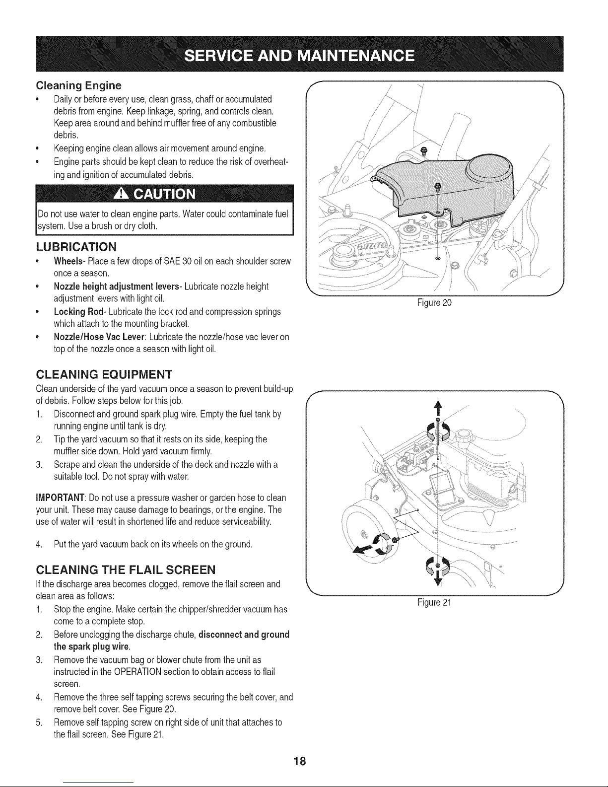
CLEANING EQUIPMENT
Cleanundersideof theyardvacuumoncea seasontopreventbuild-up
ofdebris.Followstepsbelowforthisjob.
1. Disconnectandgroundsparkplugwire.Emptythefueltankby
runningengineuntiltankis dry.
2. Tipthe yard vacuumsothatit restson itsside,keepingthe
mufflersidedown.Holdyardvacuumfirmly.
3. Scrapeandcleantheundersideofthedeckandnozzlewitha
suitabletool.Donot spraywithwater.
Figure20
f
IMPORTANT:Donot usea pressurewasherorgardenhosetoclean
yourunit.Thesemaycausedamagetobearings,ortheengine.The
useof waterwill resultin shortenedlifeandreduceserviceability.
4. Putthe yardvacuumbackon itswheelson theground.
CLEANING THE FLAIL SCREEN
Ifthedischargeareabecomesclogged,removetheflail screenand
cleanareaas follows:
1. Stopthe engine.Makecertainthechipper/shreddervacuumhas
cometoa completestop.
2. Beforeuncloggingthe dischargechute,disconnect and ground
the spark plugwire.
3. Removethevacuumbagor blowerchutefromthe unitas
instructedin theOPERATIONsectiontoobtainaccesstoflail
screen.
4. Removethethreeselftappingscrewssecuringthebeltcover,and
removebeltcover.SeeFigure20.
5. Removeselftappingscrewonrightsideof unitthatattachesto
theflail screen.SeeFigure21.
/
J
Figure21
18
Page 19
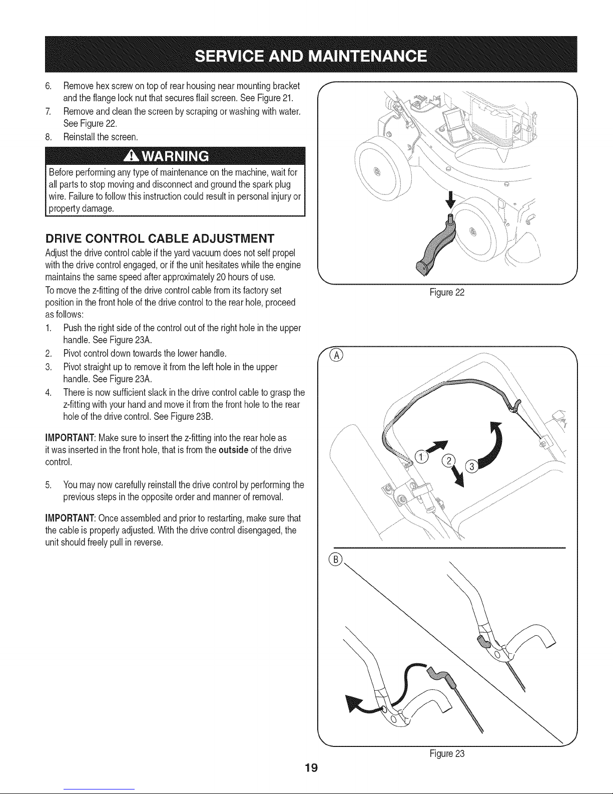
6. Removehexscrewontop of rearhousingnearmountingbracket
andtheflangelocknutthatsecuresflailscreen.SeeFigure21.
7. Removeandcleanthescreenbyscrapingorwashingwithwater.
SeeFigure22.
8. Reinstallthescreen.
Beforeperforminganytypeof maintenanceon the machine,waitfor
all partsto stopmovinganddisconnectandgroundthe sparkplug
wire. Failureto followthisinstructioncouldresultin personalinjuryor
propertydamage.
DRIVE CONTROL CABLE ADJUSTMENT
Adjustthedrivecontrolcableif theyardvacuumdoesnotselfpropel
withthedrivecontrolengaged,orif theunithesitateswhilethe engine
maintainsthesamespeedafterapproximately20 hoursofuse.
Tomovethe z-fittingofthedrivecontrolcablefromitsfactoryset
positioninthefrontholeofthedrivecontrolto therearhole,proceed
asfollows:
1. Pushtherightsideof thecontroloutof the rightholeintheupper
handle.SeeFigure23A.
2. Pivotcontroldowntowardsthelowerhandle.
3. Pivotstraightupto removeitfromtheleftholein theupper
handle.SeeFigure23A.
4. Thereis nowsufficientslackinthedrivecontrolcableto graspthe
z-fittingwithyourhandandmoveitfromthefrontholetothe rear
holeofthedrivecontrol.SeeFigure23B.
f
\
Figure22
IMPORTANT:Makesureto insertthez-fittingintothe rearholeas
itwasinsertedinthefronthole,thatis fromtheoutside ofthedrive
control.
5. Youmaynowcarefullyreinstallthedrivecontrolbyperformingthe
previoussteps inthe oppositeorderandmannerof removal.
IMPORTANT:Onceassembledand priorto restarting,makesurethat
thecableisproperlyadjusted.Withthedrivecontroldisengaged,the
unitshouldfreelypullin reverse.
\
Figure23
19
Page 20
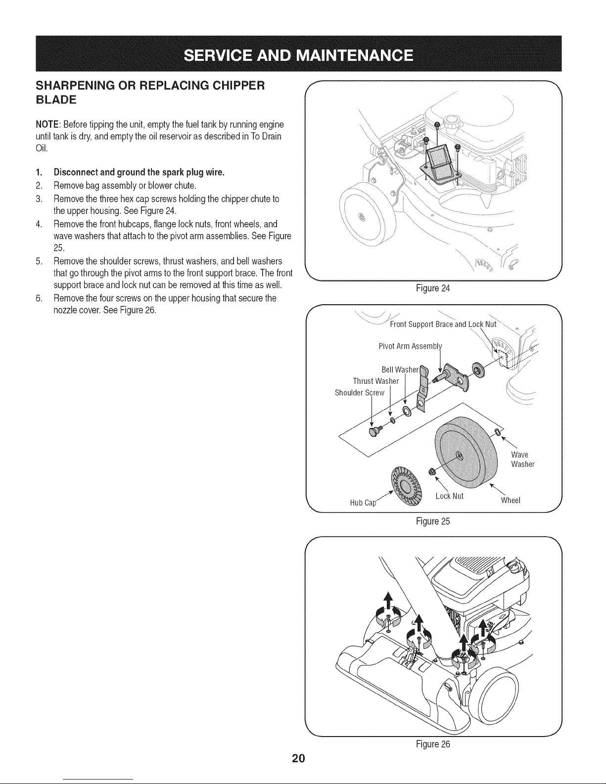
SHARPENING OR REPLACING CHIPPER
BLADE
NOTE:Beforetippingthe unit,emptythefuel tankby runningengine
untiltankisdry,andemptytheoil reservoiras describedinTo Drain
Oil.
1. Disconnectand groundthe sparkplugwire.
2. Removebagassemblyorblowerchute.
3. Removethethreehexcapscrewsholdingthe chipperchuteto
theupperhousing.SeeFigure24.
4. Removethefronthubcaps,flangelocknuts,frontwheels,and
wavewashersthatattachtothepivotarm assemblies.SeeFigure
25.
5. Removethe shoulderscrews,thrustwashers,andbellwashers
thatgothroughthepivotarmsto thefrontsupportbrace.Thefront
supportbraceandlocknutcan beremovedatthistimeas well.
6. Removethefourscrewsontheupperhousingthat securethe
nozzlecover.SeeFigure26.
f
J
Figure24
x /
..........................Front support Braceand Lock Nui
PivotArm Assembl'
BellWasher
Thrust Washer
Shoulder Screw
2O
Wave
Washer
Lock Nut
HubCa[ Wheel
J
Figure25
f
J
Figure26
Page 21

7. Carefullytilt andsupportthe unit upto provideaccessunderneath
tothe nozzlemountinghardwareandimpeller.Removethethree
shoulderboltssecuringtheblackplasticlowerflailhousingtothe
lowerhousing.Referto Figure27.
8. Tilttopofblackplasticlowerflailhousingtowardtheengineto
remove.
9. Usinga 3/16"allenwrench,removetheflat headcapscrewsthat
holdthechipperbladeto theimpeller.Thesescrewsareacces-
siblethroughtheopeningcreatedwhenthechipperchutewas
removedearlier.SeeFigure28.
10. Thenutsontheflat headcap screwscan bereachedfrom
underneathusinga 1/2-inchsocket,universal,andextension.
SeeFigure29.
11. Replaceorsharpenchipperblade.Thebladecanbe sharpened
witha fileor ona grindingwheel.
\
Black
Nozzle
ShoulderScrews
Thechipperbladeis sharp.Whensharpeningblade,wearleather
workglovestoprotectyourhandsandfollowtheoriginalangleof
grind.
12. Reassemblebyperformingthepreviousstepsin theopposite
orderand mannerofremoval.
NOTE:Tightenbladescrewsto 210- 250in-lbs.Makecertainchipper
bladeis reassembledwiththe sharpedgefacingupward.
Figure27
f
C
Flat HeadCa Screws
Chipper Blade
J
Figure28
Impeller
J
Figure29
21
Page 22

Neverstoreyardvacuumwithfuelintankindoorsorinpoorly
ventilatedareaswherefuelfumesmayreachanopenflame,spark,
or pilotlightas ona furnace,waterheater,clothesdryer,or gas
appliance.
PREPARING THE ENGINE
Forenginesstoredover30 days:
1. Topreventgumfromforminginfuelsystemoroncarburetor
parts,runengineuntilit stopsfromlackof fuelor adda gasoline
additivetothe gas inthe tank.Ifyouuseagasadditive,runthe
engineforseveralminutestocirculatetheadditivethroughthe
carburetor--afterwhichtheengineandfuelcan bestoredup to
six months.
2. Whileengineis stillwarm,changethe oil.
3. Cleanengineof surfacedebris.
PREPARING THE YARD VACUUM
• Whenstoringtheyardvacuumin an unventilatedor metalstorage
shed,careshouldbetakento rustproofthenon-paintedsurfaces.
Usinga lightoil orsilicone,coattheequipment,especiallyany
springs,bearings,andcables.
• Cleanandlubricatemowerthoroughlyas describedinthe lubrica-
tioninstructions.
• Donotusea pressurewasheror gardenhosetocleanyourunit.
• Store mowerina dry,cleanarea. Do notstorenexttocorrosive
materials,suchas fertilizer.
22
Page 23

Enginefailstostart
1. Throttlelevernotincorrectstartingposition
2. ChokecontrolnotinCHOKEposition
3. Sparkplugwire disconnected
4. Faultysparkplug
5. Fueltankemptyorstalefuel
6. Cannotpullrecoilcord
7. Safetyswitchnotdepressed
8. Safetyswitchwireisnotconnectedto
engineor notproperlygrounded
Enginerunserratically
1. Unitrunningon CHOKE
2. Sparkplugwire loose
3. Stalefuel
4. Wateror dirtin fuelsystem
5. Dirtyair cleaner
6. LowengineRPM
7. Carburetoroutofadjustment
Engineoverheats
1. Engineoil levellow
2. Airflowrestricted
Enginehesitatesat high RPMs 1. Sparkpluggap settooclose
Engineidlespoorly 1. Fouledsparkplug
2. Dirtyair cleaner
Excessivevibration 1. Loosepartsor damagedimpeller
Unitdoesnot discharge 1. Dischargeareaclogged
2. Foreignobjectlodgedin impeller
3. LowengineRPM
4. Vacuumbagis full
Rated dischargeslows
considerablyor compositionof
1. LowengineRPM
2. Chipperbladedull
dischargedmaterialchanges
Unitfailstopropelitselforslips
1. Drivecontrolcableout of adjustment
whendrivecontrolisengaged
2. Drivebeltworn ordamaged
1. Movethrottleleverto FASTposition.
2. MovechokecontroltoCHOKEposition.
3. Connectwiretosparkplug.
4. Clean,adjustgap,or replace.
5. Filltankwithclean,freshgasoline.
6. Obstructionlodgedin impeller.Disconnectspark
plugwireandremovelodgedobject.
7. Safetyswitchmustbedepressedbythefronttabon
thebag handlewhen securingthebag.
8. Connectsafetyswitchwireto engineconnectorand
groundto mountingbracket.
1. Movechokecontrolto RUNposition.
2. Connectandtightensparkplugwire.
3. Filltankwithfreshgasoline.
4. Drainfuel.Refillwithfreshfuel.
5. Cleanorreplaceaircleanerfilter.
6. Alwaysrunengineat fullthrottle.
7. ContactyourSearsParts& RepairCenter.
1. Fillenginewith properamountandtype ofoil.
2. Cleangrassclippingsanddebrisfromaroundthe
engine'scoolingfinsandblowerhousing.
1. Removesparkplugandadjustgap.
1. Replacesparkplugandadjustgap.
2. Replaceair cleanercartridge.
1. Stopengineimmediatelyanddisconnectsparkplug
wire.ContactyourSearsParts& RepairCenter.
1. Stopengineimmediatelyanddisconnectsparkplug
wire.Cleanflail screenandinsideofdischargeopen-
ing.
2. Stopengineanddisconnectsparkplugwire.Remove
lodgedobject.
3. Alwaysrunengineatfullthrottle.
4. Emptybag.
1. Alwaysrunengineatfullthrottle.
2. Replacechipperbladeor contactyourSearsParts&
RepairCenter.
1. Followadjustmentprocedurein Service& Mainte-
nancesection.
2. ContactyourSearsParts& RepairCenter.
Find this and all your other product manuals online.
Get answers from our team of home experts.
Get a personalized maintenance plan for your home.
Find information and tools to heLp with home projects.
23
Page 24

Craftsman Power Propelled Yard Vacuum Model No. 247.770131
14
44
41
54
63
38
24
Page 25

Ref.No. Part No. Description
1. 731-07001 HubCap
2. 749-04163-0637 UpperHandle
3. 720-0279 Knob
4. 710-1205 EyeBolt
5. 781-1056-0637 UpperHandleBracket
6. 710-0726 HexCapScrew5/16-12x.750
7. 720-04072A HandleKnob5/16-18
8. 710-1174 CarriageBolt
9. 731-04911 NozzleHandleClip
10. 749-04165-0637 LowerHandle
11. 711-1293 Studs
12. 710-0703 CarriageScrew1/4-20x.75
13. 712-0397A WingNut1/4-20
14. 710-1611B TT Screw,5/16-18x .750
15. 710-05073 Screw,1/4-20x .500
16. 912-0442 CapLockNut, 1/4-20
17. 710-0751 HexCapScrew1/4-20x.620
18. 681-0195 HoseBaseAdapterAssembly
(Incl.Ref.#19-21)
19. 916-0104 E Ring.500Dia
20. 932-3035 CompressionSpring
21. 711-1571 ClevisPin
22. 936-3020 FiatWasher.271IDx.630OD
23. 781-04266-4044 UpperFlailHousing
24. 746-04156 DriveControlCable
25. 731-1820 CableGuide
26. 681-04088-4044 ChipperChuteAssembly
27. 746-04155 SpeedControlCable
28. 710-1122 HexScrew,1/4-20x 2.50
29. 981-0156A-4044 HandleBracketAss'yRH
981-0155A-4044 HandleBrktAss'y LH(NotShown)
30. 717-1762 SpurGear- RH
717-1761 SpurGear- LH (NotShown)
31. 748-0457 Spacer
32. 731-2478 HoseNozzle
33. 710-3288 HexCapScrew1/4-20x 2.625
34. 723-0295 AdjustmentClamp
35. 749-1270A NozzleHandle
36. 764-0648A VacuumHose
37. 720-0369 HandlePlug
38. 731-2292 HoseAdapter
39. 747-04305A DriveControl
Ref.No. Part No. Description
40. 725-0157 CableTie
41. 918-04460 TransmissionAssembly
42. 732-04217 ExtensionSpring,.375x 2.95
43. 710-1650 ShoulderScrew,#12-24x .30x .46
44. 710-1220 Screw,#12-16x .750
45. 911-04245 ImpellerHub
46. 915-0221 DowelPin
47. 781-04082-0637 FrontWheelSupportBrace
48. 781-04081-0637 RearWheelSupportBrace
49. 914-0104 CotterPin
50. 916-0104 E-Ring
51. 936-3004 FiatWasher,.406x .875x .105
52. 712-04217 Nut,Flglk.,3/8-16
53. 738-04523 ShoulderScrew,.496x 1.605
54. 734-04596 RearWheel
55. 716-0865 SnapRing
56. 741-04242 HeightAdjustmentBearing
57. 681-04195 PivotArmAssembly
58. 720-0426 HeightAdjustmentKnob
59. 732-1026 SpringLever
60. 736-0741 BellWasher.760IDx.25OD
61. 738-1172 ShoulderScrew,.750x.500
62. 987-02051 HeightLeverAssy(Incl.Ref.#58-59)
63. 734-04568 FrontWheel
64. 710-1652 Screw,1/4-20x .625
65. 712-04065 FlangeLockNut,3/8-16
66. 731-04879 BeltCover
67. 936-0314 ThrustWasher.375IDx.70OD
68. 731-04643 WheelCover
69. 936-0369 FiatWasher,.5081Dxl .O00Dx.020
70. 738-0930 ShoulderScrew,.560x.165
71. 741-04108 DriveAxle Bushing
72. 781-04078-0637 TransmissionMountingBracket
73. 710-0597 Screw,1/4-20x 1.00
74. 712-04064 FlangeLockNut,1/4-20
75. 941-0600 Ball Bearing
76. 750-1050 FlangeSpacer,.260x.659x.517
77. 954-0369 Belt,3/8x 32.5
78. 781-04077-0637 Idler Bracket
79. 782-7598 Belt Keeper
80. 126MO2-O434-F1Engine
25
Page 26

Craftsman Power Propelled Yard Vacuum Model 247.770131
[]
45
[]
30/i_31
7
6
25
26
Page 27

Craftsman Power Propelled Yard Vacuum IViodel 247.770131
Ref.No. Part No. Description
1. 664-0094 BagAssembly
2. 681-0154-0637 ScreenAssembly
3. 710-1054 HexScrew5/16-24x 1.0
4. 981-0490 ChipperBlade
5. 781-0735 PinClip
6. 719-0329 Flail
7. 715-0166 SpiralPin
8. 711-1401 ClevisPin
9. 912-0411 LockNut,5/16-24
10. 936-0119 LockWasher,5/16
11. 981-0152 ImpellerAssembly
(Incl.Ref.#3 - 10)
12. 781-0721B-4044 LowerFlailHousing
13. 712-04063 FlangeLockNut5/16-18
14. 710-0607 Screw,5/16-18x.500
15. 981-04031 Nozzle(Incl.Ref.#16-26)
16. 747-04297 HingePin
17. 781-1064 BaseAdapterDoor
18. 732-1156 TorsionSpring
19. 926-0106 CapSpeedNut1/4
20. 711-1551 PivotRod
21. 731-04967 NozzleDoorLever
22. 710-1256 HexScrew,#8-18x 1.25
23. 750-1294 ShoulderSpacer
24. 732-3118 ExtensionSpring
25. 732-1151A NozzleDoorTorsionSpring
26. 731-2294A NozzleDoor
Ref.No. Part No. Description
27. 664-04039 Bag
28. 631-0083 ChuteAssembly
29. 736-0247 FiatWasher.375IDx 1.25OD
30. 936-0217 LockWasher3/8
31. 710-1273 HexCapScrew,3/8-24x2.75
32. 631-04118 EngineSpacerAssembly
33. 710-1008 Screw,3/8-16x 1.875
34. 925-1700 SwitchCover
35. 925-3166 SafetySwitch
36. 931-1613 SafetySwitchCover
37. 910-0224 HexWasherScrew#10-16x.50
38. 629-0920A WireHarness
39. 914-0104 CotterPin
40. 732-0962 CompressionSpring
41. 781-0778A-0637 MountingBracket
42. 747-1153 LockRod
43. 710-3195 HexCapScrew5/16-18x4.5
44. 710-3025 HexCapScrew5/16-18x.625
45. 710-1220 Screw,#12-16x.750
46. 710-0351 Screw#10- 16x.500
47. 736-0607 ExternalbWasher5/16
48. 726-0139 SpeedNut
49. 710-0726 HexindexScrew,5/16-12x.750
50. 710-1650 ShoulderScrew,#12-24x .30x .46
51. 0EM-290-012 BlowerChute
52. 629-0923 WireHarnessAdapter
-- 723-0400 SafetyGlasses(NotShown)
27
Page 28

Craftsman Engine Model No. 126M02=0434=F1 For Craftsman Yard Vacuum Model No. 247.770131
I%
15o5
615
404 @
616
635
306
7_
307
36_0_ 5_
33/.._ 40 45_:9d_
(_ 35_
868 _) _._
3@
©
718 [_
241_
287
54
I}
524
4--]
20
158
28
Page 29

Craftsman Engine IVlodel No. 1261V102-0434-F1 For Craftsman Yard Vacuum IViodel No. 247.770131
108
@
3_s
163
@ _3 ®
692 I
190
130
I 276 @
276 @
4_
883
2221 621_
188
843 843A _
968
443 '_
445
29
Page 30

Craftsman Engine Model No. 126M02=0434=F1 For Craftsman Yard Vacuum Model No. 247.770131
6s
55
1211 (__
1036E MISSIONS LABEL ]
1210
689 0
456 _
597
305
304
305A (_
332
78
455
23
30
Page 31

Craftsman Engine Model No. 126M02=0434=F1 For Craftsman Yard Vacuum Model No. 247.770131
121 CARBURETOR OVERHAUL KiT
137 O 617 (_
633 @
127 (_
163 276Q
633A
358 ENGINE GASKET SET
3
617
842 O
1095V ALVE GASKET SET
2o1_
163 _!_
524
883
31
Page 32

Craftsman Engine Model No. 126MO2=O434-F1 For Craftsman Yard Vacuum Model No. 247.770131
D = = O e
590401 CylinderAssembly
2. 399269 Kit-Bushing/Seal
3. 299819s Seal-Oil(MagnetoSide)
4. 493279 Sump-Engine
5. 590411 Head-Cylinder
7. 799875 Gasket-CylinderHead
8. 590395 BreatherAssembly
9. 699472 Gasket-Breather
10. 691125 Screw(BreatherAssembly)
11. 691781 Tube-Breather
11A. 691923 Tube-Breather
12. 692232 Gasket-Crankcase
13. 590422 Screw(CylinderHead)
15. 691680 Plug-OilDrain
16. 694478 Crankshaft
20. 399781s Seal-Oil(PTOSide)
22. 691092 Screw(CrankcaseCover/Sump)
23. 691987 Flywheel
24. 222698s Key-Flywheel
25. 590404 PistonAssembly(Standard)
590405 PistonAssembly(.020"Oversize)
26. 590402 RingSet(Standard)
590403 RingSet(.020"Oversize)
27. 691588 Lock-PistonPin
28. 298909 Pin-Piston
29. 797306 Rod-Connecting
32. 691664 Screw(ConnectingRod) (1/4-28x 1.09)
32A. 695759 Screw(ConnectingRod) (1/4-28x 1.52)
33. 590394 Valve-Exhaust
34. 590393 Valve-Intake
D = O
691270 Spring-Valve(Intake)
36. 691270 Spring-Valve(Exhaust)
37. 793756 Guard-Flywheel
40. 692194 Retainer-Valve
43. 691997 Slinger-Governor/Oil
45. 690548 Tappet-Valve
46. 691449 Camshaft
48. N/A ShortBlock- Notavailableatthisprinting
50. 794305 Manifold-Intake
51. 794306 Gasket-Intake
54. 691650 Screw(IntakeManifold)
55. 691421 Housing-RewindStarter
58. 697316 Rope-Starter
60. 281434s Grip-StarterRope
65. 690837 Screw(RewindStarter)
78. 691108 Screw(FlywheelGuard)
81. 691740 Lock-MufflerScrew
89. 692348 Plug-Oil(Cylinder)
97. 696565 Shaft-Throttle
104. 797622 Pin-FloatHinge
108. 695807 Valve-Choke
109. 498593 Shaft-Choke
117. 797574 Jet-Main(Standard)
118. 797575 Jet-Main(HighAltitude)
121. 498260 Kit-CarburetorOverhaul
125. 799869 Carburetor
127. 694468 Plug-Welch
130. 696564 Valve-Throttle
133. 398187 Float-Carburetor
134. 398188 Valve-Needle/Seat
32
Page 33

Craftsman Engine
IViodel No. 126MO2=O434=F1 For Craftsman Yard Vacuum IViodel No. 247.770131
D = O
796610 Gasket-FloatBowl
163. 795629 Gasket-AirCleaner
187. 791766 Line-Fuel(Cutto RequiredLength)
188. 693399 Screw(ControlBracket)
190. 690940 Screw(FuelTank)
202. 691829 Link-MechanicalGovernor
209. 691291 Spring-Governor
222. 692150 Bracket-Control
227. 690783 ControlLever-Governor
276. 271716 SealingWasher
287. 690940 Screw(DipstickTube)
300. 692038 Muffler
304. 493294 Housing-Blower
305. 691108 Screw(BlowerHousing)(1/4-20x .62)
305A. 590763 Screw(BlowerHousing)(1/4-20x .78)
306. 690450 Shield-Cylinder
307. 690345 Screw(CylinderShield)
332. 690662 Nut(Flywheel)
333. 590454 Armature-Magneto
334. 691061 Screw(ArmatureMagneto)
337. 799876 Plug-Spark
356. 692390 Wire-Stop
358. 794307 EngineGasketSet
365. 691688 Screw(Carburetor)
404. 690272 Washer(GovernorCrank)
425. 690670 Screw(AirCleanerCover)
443. 692523 Screw(AirCleanerPrimerBase)
D = O
491588s Filter-AirCleanerCartridge
455. 791960 Cup-Flywheel
456. 692299 Plate-PawlFriction
459. 281505s PawI-Ratchet
505. 691251 Nut(GovernorControlLever)
523. 499621 Dipstick
524. 692296 Seal-DipstickTube
525. 495265 Tube-Dipstick
562. 691119 Bolt(GovernorControlLever)
584. 697734 Cover-BreatherPassage
585. 691879 Gasket-BreatherPassage
592. 690800 Nut(RewindStarter)
597. 691696 Screw(PawlFrictionPlate)
601. 791850 HoseClamp(Green)
608. 497680 Starter-Rewind
613. 691340 Screw(Muffler)
615. 798326 Retainer-GovernorShaft
616. 698801 Crank-Governor
617. 270344s SeaI-ORing(IntakeManifold)
621. 692310 Switch-Stop
633. 691321 Seal-Choke/ThrottleShaft(ThrottleShaft)
633A. 693867 Seal-Choke/ThrottleShaft(ChokeShaft)
635. 66538s Boot-SparkPlug
668. 493823 Spacer
684. 690345 Screw(BreatherPassageCover)
689. 691855 Spring-Friction
692. 690572 Spring-Detent
33
Page 34

Craftsman Engine Model No. 126MO2=O434=F1 For Craftsman Yard Vacuum Model No. 247.770131
D = W O
690959 Pin-Locating
725. 590459 Shield-Heat
741. 795755 Gear-Timing
832. 590486 Guard-Muffler
836. 690664 Screw(MufflerGuard)
842. 691031 Seal-ORing(DipstickTube)
843. 691884 Sleeve-Lever
843A. 691895 Sleeve-Lever
847. 692047 Assembly-Dipstick/Tube
851. 493880s Terminal-SparkPlug
868. 590410 Seal-Valve
869. 691155 Seat-Valve(Intake)
870. 690380 Seat-Valve(Exhaust)
871. 590409 Bushing-ValveGuide
883. 793497 Gasket-Exhaust
957. 799585 Cap-FuelTank
D = O O
795259
968. 692298
972. 590490
975. 796611
976. 694395
1036.
Base-AirCleanerPrimer
Cover-AirCleaner
Tank-Fuel
Bowl-Float
Primer-Carburetor
Label-Emission(Availablefromauthorized
Briggs&Strattondealer)
1058. 390567TRI
1059. 692311
1095. 498528
1210. 498144
1211. 498144
1329. N/A
Owner'sManual
Kit-Screw/Washer(FuelTank)
GasketSet-Valve
Assembly-Pulley/Spring(Pulley)
Assembly-Pulley/Spring(Spring)
ReplacementEngine(NotAvailable
atthis Printing)
1330. 270962
RepairManual
CarburetorOverhaulKit ReferenceNumber121
EngineGasketSet ReferenceNumber358
ValveGasketSet ReferenceNumber1095
34
Page 35

Craftsman Power Propelled Yard Vacuum IViodel 247.770131
777S33696 777X43688
777S33695
Operation Of This Equipment May Create Sparks ThatCan Start Fires Around DryVegetation. A Spark Arrestor May Be Required,
FRONT WHEEL / VACUUM NOZZLE
HiGH HEIGHT ADJUSTER LOW
For use in To pick up wet
grass to pick material, pine
Lip Jeaves cones, acorns
and debris or material on
pavement.
The Operator Should Contact Local FireAgencies For Laws Or Regulations Relating To FirePrevention Requirements.
777122415
ITHANIO%ETHANOL
777S33694
777120916
777122416
777122428
777D18140
Do Not
Shift
unless
Engine is
Running
3372
35
Page 36

(Thispageapplicableinthe U.S.A.andCanadaonly.)
Sears Brands Management Corporation (Sears), the California Air Resources Board (CARD)
and the United States Environmental Protection Agency (U.S. EPA)
Emission Control System Warranty Statement (Owner's Defect Warranty Rights and Obligations)
EMISSIONCONTROLWARRANTYCOVERAGEISAPPLICABLETOCERTI-
FIEDENGINESPURCHASEDINCALIFORNIAIN1995ANDTHEREAF-
TER,WHICHAREUSEDINCALIFORNIA,ANDTOCERTIFIEDMODEL
California and United States Emission
TheCaliforniaAirResourcesBoard(CARD),U.S.EPAand Searsare pleased
toexplainthe EmissionControlSystemWarrantyonyour modelyear2000and
latersmalloff-roadengine(SORE).InCalifornia,newsmalloff-roadengines
mustbe designed,builtandequippedto meettheState'sstringentanti-smog
standards.Elsewherein theUnitedStates,newnon-road,spark-ignition
enginescertifiedformodelyear1997andlatermustmeetsimilarstandardsset
forthbythe U.S.EPA.Searsmustwarranttheemissioncontrolsystemonyour
YEAR1997ANDLATERENGINESWHICHARE PURCHASEDANDUSED
ELSEWHEREINTHEUNITEDSTATES(ANDAFTERJANUARY1,2001 IN
CANADA).
Control Defects Warranty Statement
enginefortheperiodsoftime listedbelow,providedtherehasbeennoabuse,
neglector impropermaintenanceofyour smalloff-roadengine.Youremis-
sioncontrolsystemincludespartssuchas thecarburetor,aircleaner,ignition
system,mufflerandcatalyticconverter.Also includedmaybeconnectorsand
otheremissionrelatedassemblies.Wherea warrantableconditionexists,Sears
will repairyoursmalloff-roadengineatnocostto youincludingdiagnosis,parts
andlabor.
Sears Emission Control Defects Warranty Coverage
Smalloff-roadenginesarewarrantedrelativeto emissioncontrolpartsdefects
fora periodof one year,subjecttoprovisionssetforthbelow.Ifanycovered
Owner's Warranty
Asthe smalloff-roadengineowner,youare responsiblefor theperformanceof
therequiredmaintenancelistedinyourOperatingand MaintenanceInstruc-
tions.Searsrecommendsthatyouretainallyourreceiptscoveringmaintenance
onyoursmalloff-roadengine,butSearscannotdenywarrantysolelyforthe
lackofreceiptsorfor yourfailuretoensuretheperformanceof allscheduled
maintenance.Asthe smalloff-roadengineowner,youshouldhoweverbe
awarethatSearsmaydenyyouwarrantycoverageifyoursmalloff-roadengine
ora parthasfaileddueto abuse,neglect,impropermaintenanceor unap-
parton yourengineis defective,the partwillbe repairedorreplacedbySears.
Responsibilities
provedmodifications.Youare responsiblefor presentingyoursmalloff-road
engineto anAuthorizedSearsServiceDealeras soonasaproblemexists.The
undisputedwarrantyrepairsshouldbecompletedina reasonableamountof
time,notto exceed30days.Ifyouhaveanyquestionsregardingyourwarranty
rightsandresponsibilities,youshouldcontacta SearsServiceRepresentative
at 1-800-469-4663.The emissionwarrantyis a defectswarranty.Defectsare
judgedonnormalengineperformance.Thewarrantyis notrelatedtoan in-use
emissiontest.
Sears Emission Control Defects Warranty Provisions
ThefollowingarespecificprovisionsrelativetoyourEmissionControlDefectsWarrantyCoverage.ItisinadditiontotheSearsenginewarrantyfornon-regulated
enginesfoundin theOperatingand MaintenanceInstructions.
1. WarrantedParts
Coverageunderthis warrantyextendsonlyto the partslistedbelow(the
emissioncontrolsystemsparts)tothe extentthesepartswerepresenton
theenginepurchased.
a. FuelMeteringSystem
• Cold start enrichmentsystem
• Carburetorand internalparts
• FuelPump
b. AirlnductionSystem
• Air cleaner
• Intakemanifold
c. IgnitionSystem
• Spark plug(s)
• Magnetoignitionsystem
d. CatalystSystem
• Catalyticconverter
• Exhaustmanifold
• Air injectionsystemor pulsevalve
e. MiscellaneousItemsUsedin AboveSystems
• Vacuum,temperature,position,timesensitivevalves
andswitches
• Connectorsandassemblies
2. LengthofCoverage
Searswarrantsto the initialownerand eachsubsequentpurchaserthat
theWarrantedPartsshallbe freefromdefects in materialsandworkman-
shipwhich causedthefailure ofthe WarrantedPartsfora periodof one
yearfromthe datethe engineis deliveredtoa retailpurchaser.
Inthe USAandCanada,a 24hourhotline, 1-800-469-4663,hasa menuof pre-recordedmessagesofferingyouenginemaintenanceinformation.
3. NoCharge
Repairorreplacementof anyWarrantedPartwill be performedat no
chargeto the owner,includingdiagnosticlaborwhichleadstothe
determinationthata WarrantedPartisdefective,ifthe diagnosticworkis
performedatanAuthorizedSearsServiceDealer.Foremissionswarranty
servicecontact yournearestAuthorizedSearsServiceDealeraslistedin
the "YellowPages"under"Engines,Gasoline,""GasolineEngines,""Lawn
Mowers,"orsimilarcategory.
4. ClaimsandCoverageExclusions
Warrantyclaimsshallbefiledin accordancewiththe provisionsofthe
SearsEngineWarrantyPolicy.Warrantycoverageshall beexcludedfor
failuresof WarrantedPartswhichare notoriginalSearspartsor because
ofabuse,neglector impropermaintenanceassetforth inthe Sears
EngineWarrantyPolicy.Searsisnotliableto coverfailuresof Warranted
Partscausedby theuseof add-on,non-original,ormodifiedparts.
5. Maintenance
AnyWarrantedPartwhichis notscheduledfor replacementasrequired
maintenanceor whichis scheduledonlyforregularinspectiontothe effect
of"repairor replaceas necessary"shallbe warrantedastodefectsfor the
warrantyperiod.AnyWarrantedPartwhich isscheduledfor replacement
asrequiredmaintenanceshallbewarrantedastodefectsonlyforthe
periodoftime uptothe firstscheduledreplacementfor that part.Any
replacementpart that isequivalentin performanceanddurabilitymay
beusedin the performanceofanymaintenanceorrepairs.Theowneris
responsibleforthe performanceof all requiredmaintenance,asdefinedin
the SearsOperatingand MaintenanceInstructions.
6. ConsequentialCoverage
Coveragehereundershallextendto thefailureof anyenginecomponents
causedbythe failureof anyWarrantedPartstill underwarranty.
GDOC-100188Rev.B
36
Page 37

Look For Relevant Emissions Durability Period and
Air index information On Your Engine Emissions Label
Engines that are certified to meet the California Air Resources Board (CARB) Tier 2 Emission Standards must
display information regarding the Emissions Durability Period and the Air Index. Sears Brands Management
Corporation makes this information available to the consumer on our emission labels.
The Emissions Durability Period describes the number of hours of actual running time for which the engine is
certified to be emissions compliant, assuming proper maintenance in accordance with the Operating & Mainte-
nance Instructions. The following categories are used:
Moderate: Engine is certified to be emission compliant for 125 hours of actual engine running time.
Intermediate: Engine is certified to be emission compliant for 250 hours of actual engine running time.
Extended: Engine is certified to be emission compliant for 500 hours of actual engine running time.
For example, a typical walk-behind lawn mower is used 20 to 25 hours per year. Therefore, the Emissions
Durability Period of an engine with an intermediate rating would equate to 10 to 12 years.
The Air index is a calculated number describing the relative level of emissions for a specific engine family. The
lower the Air Index, the cleaner the engine. This information is displayed in graphical form on the emissions label.
After July 1,2000, Look For Emissions Compliance Period
On Engine Emissions Compliance Label
After July 1, 2000 certain Sears Brands Management Corporation engines will be certified to meet the United
States Environmental Protection Agency (USEPA) Phase 2 emission standards. For Phase 2 certified engines, the
Emissions Compliance Period referred to on the Emissions Compliance label indicates the number of operating
hours for which the engine has been shown to meet Federal emission requirements.
For engines less than 225 cc displacement, Category C = 125 hours, B = 250 hours and A = 500 hours.
For engines of 225 cc or more, Category C = 250 hours, B = 500 hours and A = 1000 hours.
This isa generic representation of the emission label typically found on a certified engine.
FAMILYYBSXS.3192VA 274812
GDOC-100182Rev.B
37
Page 38

Congratulations on making a smart purchase. Your new Craftsman® product is designed and
manufactured for years of dependable operation. But like all products, it may require repair
from time to time. That's when having a Repair Protection Agreement can save you money and
aggravation.
Here's what the Repair Protection Agreement* includes:
[] Expert service by our 10,000 professional repair specialists
[] Unlimited service and no charge for parts and labor on all covered repairs
[] Product replacement up to $1500 if your covered product can't be fixed
[] Discount of 25% from regular price of service and related installed parts not covered by the
agreement; also, 25% off regular price of preventive maintenance check
[] Fast help by phone - we call it Rapid Resolution - phone support from a Sears representative.
Think of us as a "talking owner's manual."
Once you purchase the Repair Protection Agreement, a simple phone call is all that it takes for you
to schedule service. You can call anytime day or night, or schedule a service appointment online.
The Repair Protection Agreement is a risk-free purchase. If you cancel for any reason during the
product warranty period, we will provide a full refund. Or, a prorated refund anytime after the
product warranty period expires. Purchase your Repair Protection Agreement today!
Some limitations and exclusions apply. For prices and additional information in the U.S.A.
call 1=800=827=6655.
*Coverage in Canada varies on some items. For full details call Sears Canada at 1=800=361=
6665.
Sears Installation Service
For Sears professional installation of home appliances, garage door openers, water heaters, and
other major home items, inthe U.S.A. or Canada call 1=800=4=MY=HOME®.
38
Page 39

Declaraci6n de garantia ....................... Pagina 39
Practicas operaci6n seguras ............... Pagina 40
Montaje ................................................ Pagina 44
Operaci6n ............................................ Pagina 48
Servicio y Mantenimiento .................... Pagina 52
Almacenamiento fuera de temporada ....Pagina 58
Soluci6n de problemas ...................... Pagina 59
Etiquetas de seguridad ....................... Pagina 7
Lista de piezas ........................................ Pagina 24
Acuerdo de Protecci6n Para
Reparaciones ....................................... Pagina 63
NOmero de servicio ..................... Cubierta posterior
ARTESANODE DOSANOS DEGARANTJA
PORDOSANOS(S)apartirdelafechadecompra,esteproductoest&garantizadocontracualquierdefectodematerialo manodeobra.Un
productodefectuosorecibir&la reparaci6no la sustituci6nsi la reparaci6nnoestAdisponible.
Paraobtenerinformaci6ndetalladacoberturade lagaranfiaparaobtenerla reparaci6no sustituci6ngratuita,visiteelsitioweb:www.craftsman.com
EstagarantiacubrelosdefectosSOLOdematerialesy fabricaci6n.Lagarantianoincluye:
• Elementosreutilizablesquepuedengastarseporel usonormaldentrodelperiododegarantia,talescomolascuchillas,bujias,filtrode
aire,pantallade desgranadoyunabolsa.
• ProductodaSosresultantesde los intentosdelusuariodemodificaci6ndelproducto,reparaci6no causadosporaccesoriosde
productos.
• Reparacionesnecesariasdebidoalaccidenteo por nooperaro mantenerelproductosegOnlas instruccionesprovistas.
• El mantenimientopreventivoo reparacionesnecesariasdebidoa unamezclaincorrectade combustible,combustiblecontaminadoo
pasado.
Estagaranfiaes inv&lidasiesteproductoseutilizaal mismotiempola prestaci6nde servicioscomercialeso si sealquilaaotrapersona.
Estagarantialeotorgaderechoslegalesespecificos,yustedtambi_npuedetenerotrosderechosquevariandeestadoa estado.
Sears Brands Management Corporation, Hoffman Estates, IL 60179
Serie: 675
Tipode aceitedelmotor: SAE30
Capacidaddeaceitedel motor: 18onzas
Capacidaddecombustible: 1.5cuartos
Separaci6nde lasbujias: .020"
NSmerode modelo ..........................................................
N_merode serie ..............................................................
Fechade compra .............................................................
RegistrearribaelnOmerodel modelo,elnOmerode seriey lafecha
decompra
©SearsBrands,LLC 39
Page 40

Lapresenciade estesirnboloindicaquesetratade instrucciones
irnportantesde seguridadquesedebenrespetarparaevitar
ponerenpeligrosu seguridadpersonaly/omaterialy lade otras
personas.Leay sigatodaslasinstruccionesdeestemanualantes
de poneren funcionarnientoestarn_.quina.Si no respetaestas
instruccionespodriaprovocarlesionespersonales.Cuandoveaeste
sirnbolo,ipresteatenci6nala advertencia!
Estarn_.quinarueconstruidaparaseroperadadeacuerdocon
lasreglasde seguridadcontenidasenestemanual.AIigualque
concualquiertipodeequipornotorizado,undescuidoo errorpor
partedeloperadorpuedeproducirlesionesgraves.Estarn_.quina
escapazde arnputarrnanosy piesy dearrojarobjetoscongran
fuerza.De norespetarlasinstruccionesde seguridadsiguientesse
puedenproducirlesionesgraveso la rnuerte.
PROPOSICION 65 DE CALIFORNIA
Elescapedel motordeesteproducto,algunosde suscornponentes
y algunoscornponentesdelvehiculocontieneno liberansustancias
quirnicasqueelestadode Californiaconsideraque puedenproducir
c_.ncer,defectosde nacirnientouotrosproblernasreproductivos.
CAPACITACION
• Lea,entienday curnplatodaslasinstruccionesincluidasen
la rnAquinayen los rnanualesantesde rnontarlayutilizarla.
Guardeestemanualenun lugarseguroparaconsultasfuturasy
regulares,asi cornoparasolicitarrepuestos.
• Leael ManualdelOperadory sigatodaslasadvertenciase
instruccionesdeseguridad.El fracasodehacerasi puedecausar
la heridaseriaal operadory/opersonaspresentes.ParaIlarnada
de preguntas,1-800-659-5917.
• Farniliaricesecontodosloscontrolesysuoperaci6nadecuada.
Sepac6rnodetenerla rn_.quinayc6rnodesengranarloscontroles
r_.pidarnente.
• No perrnitanuncaquelosniffosrnenoresde 16afrosutilicen
estarn_.quina.Losniffosde 16afrosy rn_.srnayoresdeben
leerycornprenderlasinstruccionesde operaci6nylas reglas
de seguridadcontenidasen estemanual,y tarnbi_ndebenser
capacitadosy estarsupervisadosporunode lospadres.
• Nuncaperrnitaquelosadultosoperenestarn_.quinasin recibir
antesla instrucci6napropiada.
• MantengaalostranseQntes,ayudantes,rnascotasy niffosal
rnenosa75piesde la rn_.quinarnientrasest,.operando.Detenga
la rn_.quinasialguienentraenla zona.
• Nuncaenciendaun motorenespacioscerradoso enunazona
conpocaventilaci6n.Elescapedel motorcontienernon6xidode
carbono,un gasinodoroy letal.
• No pongalas rnanosolospiescercadelaspiezasrotatoriaso
en lasc_.rnarasde alirnentaci6nnien laaberturade descarga.El
contactocon el motorrotatoriopuedeproducirla arnputaci6nde
dedos,rnanosopies.
• Nuncatratededestapar[atornade alirnentaci6no la aberturade
descarga,nitratede sacaro vaciarla bolsade laaspiradora,ni
de revisaryrepararlarn_.quinarnientrasel motorest,.enrnarcha.
Su responsabilidad--Restrinja el usode estarn_.quina
rnotorizadaalas personasque lean,cornprendany respetenlas
advertenciase instruccionesqueaparecenenestemanualyen la
rn_.quina.
iGUARI)E ESTASINSTRUCCIONES!
Apagueel motoryesperehastaquetodaslaspiezasrn6vilesse
hayandetenidoporcornpleto.Desconecteel cablede labujiay
p6ngalode rnaneraquehagarnasacontrael motor.
PREPARATIVOS
• Inspeccionerninuciosarnenteel _.readondeutilizar_,el equipo.
Retiretodaslas piedras,botellas,latasu otrosobjetosextra_os
que puedanserlevantadoso arrojadoscausandolesiones
personaleso da_osa larn_.quina.
• Paraprotegerselosojosutilicesiernpreanteojoso antiparras
de seguridadrnientrasoperala rn_.quinao rnientraslaajusta
o repara.Losobjetosarrojadosquerebotanpuedenlesionar
gravernentelavista.
• Utilicezapatosdetrabajoresistentes,desuelafuerte,asi corno
pantalonesy carnisasajustados.Las prendassueltaso las
alhajaspuedenquedaratrapadasen laspiezasrn6viles.Nunca
utilicela rn_.quinadescalzoocon sandalias.Utiliceguantesde
trabajodecuerocuandoalirnentematerialporelcanaldela
cortadora.
• Antesde encenderlarn_.quinacontrolequetodoslospernosy
tornillosest_nbienajustadosparacornprobarquela rn_.quinase
encuentraen condicionessegurasdeoperaci6n.Adern_.s,realice
una inspecci6nvisualde larn_.quinaa intervalosfrecuentespara
controlarsila rnisrnaest,.da_ada.
• Mantengao reernplacelasetiquetasdeseguridadeinstrucciones
segQnseanecesario.
Manejosegurode la gasolina
Paraevitarlesionespersonaleso da_osrnaterialesseasurnarnente
cuidadosoal rnanipularlagasolina.Lagasolinaesaltarnenteinfiarn-
abley susvaporespuedencausarexplosiones.Sepuedelesionar
gravernentesiderrarnagasolinasobreustedo sobrela ropayaquese
puedeencender.L_.vesela piely c_.rnbiesede ropade inrnediato.
• Utilices61orecipientesparagasolinaautorizados.
4O
Page 41

• NuncaIleneloscontenedoresen elinteriordeun vehiculo
o carni6nocajadecarnionetacon recubrirnientospl_.sticos.
Coloquesiernprelos recipientesenel pisoy lejosdelvehiculo
antesde Ilenarlos.
Retireel equipoa gasolinadelcarni6norernolquey II_neloen
el piso.Si estonoesposible,entoncesIlenedichoequipoenun
rernolqueconun recipienteport_.til,en vezdedesdeun dispen-
sadordegasolina.
Mantengala boquillade llenadoencontactoconel hordedela
entradadeltanquedegasolinaocontenedorentodo rnornento
hastaqueest_Ileno.Noutiliceundispositivoparaabrir/cerrarla
boquilla.
Apaguetodosloscigarrillos,cigarros,pipasyotrasfuentesde
cornbusti6n.
Nuncacarguecombustibleen la rn_.quinaen unespaciocerrado.
Nuncasaquelatapa delgas ni agreguecombustiblernientrasel
motorest,.calienteo enrnarcha.Dejequeel motorseenfrie por
Iornenosdosrninutosantesdevolvera cargarcombustible.
Nuncarecargueel tanquede combustible.Lleneel tanqueno
rn_.sde 1/2 pulgadapordebajode labasedelcuellodelfiltro
paradejarespacioparala dilataci6ndelcombustible.
• Vuelvaa colocarla tapade lagasolinay ajOstelabien.
• Lirnpielagasolinaderrarnadasobreelmotory elequipo.Traslade
la rn_.quinaaotrazona.Espere5rninutosantesdeencenderel
motor.
• Nuncaalrnacenela rn_.quinao elrecipientede combustibleen
unespaciocerradodondehayafuego,chispasoluzpiloto(por
ejernplo,hornos,calentadoresdeagua,calefactores,secadores
de ropa,etc.)
• Parareducirelriesgodeincendiornantengalarn_.quinalirnpia
depasto,hojasyde acurnulaci6nde otrosdesechos.Lirnpielos
derrarnesdeaceiteo combustibley saquetodoslos desechos
ernbebidosconcombustible.
OPERACION
• No pongalas rnanosolospiescercadelaspiezasrotatoriaso
enlasc_.rnarasdealirnentaci6nni en laaberturadedescarga.El
contactocon el motorrotatoriopuedeproducirla arnputaci6nde
dedos,rnanosopies.
• Antesdeencenderlarn_.quinacornpruebequeel canaldela
cortadora,latornade alirnentaci6ny lac_.rnarade corteest_.n
vadas ysindesechos.
• Inspeccionerninuciosarnentetodoel materialquedeseatriturar
ysaquelosobjetosrnet_Jicos,piedras,botellas,latasuotros
objetosextra_osquepuedenocasionarlesionesoda_arla
rn_.quina.
Sielmotorgolpeaunobjetoextra_oo si la rn_.quinaernpiezaa pro-
ducirunsonidopococornOnounavibraci6n,apagueelmotorde
inrnediato.Dejequeelmotorse detengaporcornpleto.Desconecte
el cabledelabujia,p6ngalode rnaneraquehagarnasacontrael
motory sigaestospasos:
a. Inspeccionela rn_.quinaparaversi est,.da_ada.
b. Repareoreernplacelaspiezasda_adas.
c. ControlesihaypiezasflojasyajQstelasparaasegurarquela
rn_.quinafuncionede rnaneraseguray continua.
• Noperrnitaquese acurnulematerialprocesadoenlazonade
descarga.Elrnisrnopuedeobstaculizarladescargaadecuada
y provocarel retornodelmaterialatravesde laaberturade
alirnentaci6n.
• Nointentetriturarni picarmaterialdemayortarna_oal espe-
cificadoen larn_.quinao enestemanual.Sepodrianproducir
lesioneso da_os.
• Nuncatratede destaparla tornade alirnentaci6no laabertura
de descargarnientrasel motorest,.en rnarcha.Apagueel motor
y esperehastaquetodaslaspiezasque sernuevensehayan
detenidoporcornpleto,desconecteel cablede labujfay p6ngalo
de rnaneraquehagarnasacontraelmotorantesde sacarlos
escombros.
• Nuncaoperela rn_.quinasinquelabolsade laaspiradorayel
canalde descargaest_nconectadosa larn_.quinacornocorre-
sponde.Nuncavade ni carnbielabolsade la aspiradorarnientras
el motorest,.en rnarcha.Elextrernoconcierredelabolsade la
aspiradoradebequedarcerradotodoel tiernpornientrasla opera.
• Nuncaoperela rn_.quinasiel picode ingresoo la uni6nopcional
parala rnangueranoest_.nconectadosa la rn_.quinaadecu-
adarnente.Nuncaintenteconectarocarnbiarningunadeestas
unionesrnientrasel motorest,.en rnarcha.
• Mantengatodoslosprotectores,desviadoresy dispositivosde
seguridadensu lugaryen buenascondiciones.
• Mientrasalirnentamaterialdentrode la rn_.quinarnantengasu
rostroysu cuerpodetr_.sy haciaun costadodelcanalde la
cortadoraparaevitarlesionesporretrocesosaccidentales.
• Nuncaopereestarn_.quinasinbuenavisibilidadoilurninaci6n.
Siernpredebeestarsegurode queest,.bienafirrnadoysostenga
bienlasrnanijas.
• Noopereestarn_.quinaensuperficiescon grava.
• Noopereestarn_.quinaestandobajolos efectosdelalcoholo de
drogas.
• Elsilenciadoryel motorse calientany puedenproducirquerna-
duras.Nolos toque.
• Nuncalevanteotransportela rn_.quinacuandoel motorest,.
encendido.
Sisepresentansituacionesquenoest_.nprevistaseneste
manualseacuidadosoy useel sentidocornQn.Marquepara
contactareldepartarnentodeatenci6nalclientey obtenerel
nornbredesu distribuidorrn_.scercano.
41
Page 42

MANTENIMIENTO Y ALMACENAMIENTO
• Nuncarnanipulelosdispositivosde seguridaddernanera
irnprudente.Controleperi6dicarnentequefuncionende forrna
adecuada.
• Controlefrecuenternentequetodoslospernosytornillosest_n
bienajustadosparacornprobarquela rn_.quinaseencuentraen
condicionessegurasdefuncionarniento.Adern_.s,realiceuna
inspecci6nvisualdelarn_.quinaparacontrolarsi larnisrnaest,.
da_adayrep_.reladeser necesario.
• Antesde lirnpiar,repararo inspeccionarla rn_.quina,detengael
motorycornpruebequeel rnisrnoyquetodaslaspiezasrn6viles
sehallandetenido.Desconecteel cablede labujiay p6ngalo
de rnaneraquehagarnasacontrael motorparaevitarquese
enciendadernaneraaccidental.
• Nocarnbielaconfiguraci6ndel reguladordel motorni acelere
dernasiadoel rnisrno.El reguladorcontrolalavelocidadrn_.xirna
seguradeoperaci6ndelmotor.
• Mantengaoreernplacelasetiquetasde seguridade instrucciones
segQnseanecesario.
• Sigalasinstruccionesde estemanualparacargar,descargar,
transportary alrnacenardernaneraseguraestarn_.quina.
• Nuncaalrnacenela rn_.quinao elrecipientedecombustibleenun
espaciocerradodondehayafuego,chispaso luzpilotocornopor
ejernplo,calentadoresdeagua,hornos,secadoresde ropa,etc.
• Dejequela rn_.quinaseenfriepot Io rnenos5rninutosantesde
guardarla.
• Consultesiernpreel manualdel operadorparaconocerlas
instruccionesadecuadasparael alrnacenarnientofuerade
ternporada.
• Seg_nla Cornisi6ndeSeguridadde Productosparael Consu-
rnidorde losEstadosUnidos(CPSC)y laAgenciade Proteccidn
Arnbientalde los EstadosUnidos(EPA),esteproductotieneuna
vidaOtilmediade siete(7)a_os,6 60horasde funcionarniento.
AI finalizarla vidaOtilmedia,adquieraunarn_.quinanuevao
hagainspeccionaranualrnente_staporundistribuidordeservicio
autorizadoparacerciorarsede quetodoslossisternasrnec_.nicos
yde seguridadfuncionancorrectarnenteyno tienenexcesivo
desgaste.Si noIohace,puedenproducirseaccidentes,lesiones
o rnuerte
• Sidebevaciarel tanquedecombustible,h_.galoal airelibre.
• Respetelasnorrnasreferentesa ladisposici6ncorrectay las
reglarnentacionessobregas,combustible,etc.paraprotegerel
medicarnbiente.
NO MODIFIQUE EL MOTOR
Paraevitarlesionesgraveso larnuerte,nornodifiqueel motorbajo
ningunacircunstancia.Si carnbialaconfiguracidndel reguladorel
motorpuededescontrolarseyoperara velocidadesinseguras.Nunca
carnbielaconfiguracidndef_.bricadel reguladordelmotor.
AVISO REFERIDO A EMISIONES
Losrnotoresqueest&ncertificadosy curnplenconlas regulaciones
de ernisionesfederalesEPAy de CaliforniaparaSORE(Equipos
peque_ostodoterreno)est_.ncertificadosparaoperarcongasolina
cornOnsinplornoy puedenincluirlossiguientessisternasde control
de ernisiones:Modificacidnde motor(EM)ycatalizadorde tresvias
(TWO)siest_.nequipadosdeesarnanera.
GUARDACHISPAS
Estarn&quinaest,.equipadaconunmotorde cornbusti6ninternay
nodebeserutilizadaen o cercade unterrenoagrestecubiertopor
bosque,rnalezaso hierbaexceptosiel sisternade escapedelmotor
est,.equipadocon unarnortiguadorde chispasque curnplaconlas
leyeslocaleso estatalescorrespondientes,encasode habedas.
Si seutilizaunarnortiguadorde chispasel operadorIodebernantener
en condicionesde usoadecuadas.EnelEstadode Californialas
rnedidasanteriorrnenternencionadassonexigidasporIcy(Arficulo
4442del Cddigode RecursosPOblicosde California).Esposible
queexistanleyessirnilaresenotrosestados.Lasleyesfederalesse
aplicanenterritoriosfederales.
Puedeconseguirelarnortiguadordechispasparael silenciadora
travesdesu distribuidorautorizadode rnotoreso poni_ndoseen
contactoconel departarnentodeservicios.
42
Page 43

SilVIBOLOSDE SEGURIDAD
Estap&ginarepresentay describelaseguridadlossimbolosquepuedenparecerenesteproducto.Lea,comprenda,y sigatodasinstrucciones
enla m_quinaantesprocurarparareuniry operar.
LEA EL MANUAL(S) DEL OPERADOR
Lea, comprenda, y siga todas instrucciones en el manual (manuales) antes procurar para
reunir y operar
ADVERTENCIA-- GIRANDO HOJAS
Mantenga manos fuera de aperturas de cala y descarga mientras m_fiquina corre. Alli giran
hojas adentro
O O
I-ml
llm
ESPECTADORES
Mantenga a espectadores, los animales favoritos, y los ni_os pot Io menos 75 pies de la
m_iquina mientras est,1 en la operaci6n. Pare m_iquina si cualquiera entra el _irea. eet from
the machine while it is in operation. Stop machine if anyone enters the area.
ADVERTENCIA-- OBJETOS TIRADOS
Esta m_iquina puede recoger y poder tirar y los objetos que pueden rebotar.
PROTECCION DE OJO
Siempre Ileve gafas de seguridad o gafas de seguridad al operar esta m_fiquina.
ADVERTENCIA-- GASOLINA ESINFLAMABLE
Allow the engine to cool at least two minutes before refueling.
ADVERTENCIA-- MONOXIDO DE CARBONO
Nunca corra un motor dentro ni en un _irea mal ventilada. El escape del motor contiene
mon6xido de carbono, un gas inodoro y mortal.
43
Page 44

IMPORTANTE:Estaunidadseenviasin gasolinaniaceiteenel mo-
tor.Antesdeoperarlam_.quinacargueel motorcongasolinay aceite
comoseindicaenla secci6ndeOperaci6nenestemanual.
NOTA:Lasreferenciasa los ladosderechoeizquierdodela aspira-
doraparapatiossehacenobservandola m_.quinadesdela posici6n
deoperaci6n.
APERTURA DE LA CAJA DE CARTON
1. Cortecadaunade lasesquinasde la cajaverticalmente,de la
partesuperiora la base.
2. Saquetodaslaspiezassueltas.
3. Quiteel materialdeempaquesuelto.
COIVlO SACAR LA UNIDAD DE LA CAJA
1. Elevelaunidaddesdela parteposteriorparasepararladel
materialde la cajaquequededebajo,y hagarodarla unidad
fuerade lacaja.
2. Verifiquecuidadosamentesi enla cajaquedaalgunapartesuelta.
NOTA:AsegQresede nodoblarloscablesmientrasextraede lacaja
laspartessueltaso toda la unidad.
f
Control de latransmisi6n
Soporte parala manija de
la manguerasuperior
Tuerca
mariposa /7'
Perilla manual
Soportepara la manija de la
manguerainferiort
j Manija superio_r
Guia de I Control de
cuerda velocidad
Guiadel
cable
Tornillo
carro
Manija
Tuercade
mariposa
Bolsa
PIEZAS SUELTAS DENTRO DE LA CAJA
(Yea la figura 1)
• Manijasuperioreinferior
• Montajedela manguera
• Bolsa
• Canaldesoplado
• Anteojosdeseguridad
• Aceiteparamotor(puedeestarenel interiorde la bolsa)
• Manualdeloperador
\
Montaje de la
manguera
Botellade aceite paramotor Canaldesoplado
Manualdel operador d_ _
__ Anteojos de segurida
Figura 1
44
Page 45

MONTAJE DE LA iVIANIJA
1. Saquelosbrochesdehorquillade lossoportesde larnanija,y
saquelostornillosdelcarroylastuercasdernariposadelarnanija
inferior.
a. SitOelosagujerosinferioresde larnanijainferiorsobre
lospernosde los soportesdelarnanija,yasegOreloscon
brochesdehorquilla.Vealafigura2.
b. Insertelostornillosdelcarrodesdeel ladodeafueraa trav_s
delagujerosuperiordelarnanijainferiory asegOreloscon
tuercasdernariposa.Veala figura2.
2. a. Desplieguelarnanijasuperiorhastaquequedealineadacon
la rnanijainferior.AsegQresequela guiade lacuerdaest_
situadaa laderechade la rnanijasuperior.Veala figura3.
[MPORTANTE:AsegQresedeenrutarloscablesfuerade larnanija
inferior.Asirnisrno,no prenseloscablesrnientraslevantalas rnanijas.
b. Parasujetar[asdos rnanijasajustelas periiiasde[arnanija
(lospernosdel carrodebenestarcolocadosdeforrna
adecuadaen[a rnanija).Vea[afigura3.
.
Tirede lasdos unionesdelcableunidasa los cables,ajuste
aproxirnadarnente8 pulgadasdecadaextrernode cable,y ubique
loscablesen suguia.
.
Aflojela tuercade rnariposaquesostienela guiade lacuerd
contrael ladoderechodela rnanijasuperior.
a. Tirelentarnentede lacuerdadearranqueparasacarladel
motor.Vealafigura4.
b. Deslicelacuerdadearranqueen la guia.Ajustela tuercaa
rnariposa.Vealafigura4.
Guiadela
cuerda
J
Figura4
45
Page 46

f
/
i' !i ee el \\\
Figura5
INSTALACI6N DEL iVIONTAJE DE LA
iVlANGUERA
1. a. Desliceeladaptadorpararnangueradel rnontajede la rnisrna
haciaelinteriordeladaptadorbaseubicadoala izquierday al
frentedela aspiradoraparapatios.Veala figura5.
b.Tire delpernocon resortedelladoexteriorde la base,y ponga
el pernoen Nneaconel primeragujero(elrn_.scercanoal
extrernodel tubo)deladaptadorpararnanguera.
c. Suelteelpernoparaajustarlarnangueraensu lugar.
2. a. Prirnero,unaa presi6nla rnanijadelarnangueraconel soporte
parala rnanijadela rnanguerasuperior,ydespu6scon el
soportede la rnanguerainferior.
b. SitQeel ca_ode larnangueraa finalcurvode mangoalcanalde
lacortadora.Vealafigura6.
iViONTAJE DE LA BOLSA
Sostengalarnanijadela bolsaconunarnanoydeslicela variNade
seguridaddelsoportedernontajehaciaelmotorconla otrarnano.
Useel extrernodelsoportede rnontajecornopalancacuando
deslicelavarilladeseguridad.
a. Deslicela bolsapotencirnadel bordedela aberturade
descargaysueltelavariNade seguridadparaajustarla bolsa
en sulugar.Vealafigura7.
b. Unael brochede labolsaa presi6nconla partesuperiorde la
rnanijainferior.
c. Coloquelastirasinferioresde la bolsaporencirnadelaparte
superiordela rnanijainferior,enganch_.ndolasen lospernos.
Vealafigura7.
Figura6
NOTA:El bot6ninterruptorde bolsa/ canal,unidoa la rn6nsulade
rnontaje,debequedarpresionadototalrnenteporla puntadela aleta
delanterasituadaenla rnanijadela bolsacuandoajustedichabolsa,
o el motornoarrancar_..
J
Figura7
46
Page 47

INSTALAR EL CANAL DE SOPLADO f
NOTA:hayquerefirarlabolsaantesdeinstalarel canalde soplado.
1. a. Tomeelcanaldesopladoconunarnanoy deslicela varillade
seguridaddel soportede rnontajehaciael motorcon laotra
rnano.Useelextrernodelsoportede rnontajecornopalanca
cuandodeslicelavarillade seguridad.Vealafigura8.
b. Desliceelcanalde sopladoporencirnadelhordede laabertura
dedescarga,y sueltelavarillade seguridadparaajustarel
canalen sulugar.
c. Aurnentela alturadelpicoal rrn_.xirnocuandoutiliceelcanalde
soplado.Consultelasinstruccionesparaajustarlaalturadel
picoen la siguientesecci6n.
NOTA:Elbot6ninterruptorde bolsa/ canalunidoala rn_nsulade
rnontajedebequedarpresionadototalrnenteporla puntade laaleta
delanterasituadaen el canaldesoplado,oel motornoarrancar&
Siernpredetengael motorydesconecteelcabledela bujiaantes
dehacercualquiertipode mantenirnientoo ajustes.Utilicesiernpre
anteojosde seguridaddurantelaoperaci6no rnientrasajustao
reparaesteequip&
/
J
Figura8
AJUSTE DE LA ALTURA DEL PICO
Puedeajustarel picoen seisposicionesquevariandesde5/8"a
4-1/8"dedistanciadelsuelo.DebeajustarlaalturadelpicosegOnlas
condicionesdel patio.
1. Oprirnala palancade ajustede laalturadel picohaciala rueda.
Veala figura9.
2. Muevalapalancadeajustede alturahaciadelanteo haciaatr_.s,
paramoverel picoarribao abajo.AsegOresedequearnbas
palancasest_.nenla misrnaposici6n.
3. Liberela palancahaciala cubierta.
NOTA:engeneral,levantelaalturadelpicoparaaspirarunacapa
gruesadehojaso parausarelcanalde soplado.Bajelaalturadel
picoparasuperficiesrn_.slisas.
f
J
Figure9
47
Page 48

f
de latransmisi6n Controldel Control de
Control develocidad estrangulador obturaci6n
Manija del
arrancador
Bolsa
Soporte parala
manija de la
ijade la bolsa
manguera inferior
Llenadode aceite
Montaje de la
manguera
Llenado de
dela
Manija de
manguera
Canalde Canaldel_
soplado cortadora
la
delpico /
manguera de la
aspiradora
Palancadeajuste
de laaltura del
pico
Figura10
Ahoraqueyahaajustadosuaspiradoraparapatiosparala operaci6n,
famiNarfcesecon suscontrolesycaracterfsticas.Estossedescriben
yse ilustranenesta p_.gina.Esteconocimientole permitir_,utilizarsu
nuevoequipoa sum_.ximacapacidad.
Ai operarunacortadoratrituradorapuedeserqueobjetosextra_os
seanarrojadosa losojos Iocualpuededa_arlosgravemente.Utilice
siemprelos anteojosdeseguridadprovistosconesta unidado
protectoresparaojosmientrasoperaymientrasrealizaajusteso
reparaciones.
CANAL DE LA CORTADORA
Permiteque lasramaspequeSasde hasta1-1/2"de di&metroingresen
al motorparapicarlas.Yeala figura9.
CONTROL DE VELOCIDAD
Situadoenlaparteizquierdade la manijaizquierda,el controlde
velocidadse utilizaparaseleccionarlavelocidadde avancedela
aspiradoraparapatios.
PALANCA
Losdesechosqueseacumulanen lospatioscomoporejemplolashojas
olasagujasdelospinossepuedenaspirarconelpicoparapicarlos.
lJ
CONTROL DE LA TRANSMISION
Ubicadosobrela partedeabajodela manijasuperior,elcontroldela
transmisi6nse utilizaparaengranar/ desengranarlas ruedas.Apriete
pot completoel controlde latransmisi6ncontralamanijasuperior
paraengranarlasruedas,y su_lteloparadesengranarlas.(NOsuelte
el embrague).
IMPORTANTE: Muevael control de velocidad s61ocuando el motor
est_ en marcha. Si cambia el ajuste dei control de velocidad con el
motor apagado, su aspiradora para patios puede resultar daSada.
MANIJA DE LA BOLSA
Seutilizaparatomarlabolsaparacolocarla,sacarlayvaciarla.Vealafigura10.
CANAL DE SOPLADO
Cuandose Iounealaunidadelcanaldesopladoseutilizaparasoplaro
esparcirpotlospatioslosdesechosqueseacumulanenlosmismoscomo
potejemplolashojas,lasagujasdelospinosolasramaspeque_as.
MONTAJE DE LA MANGUERA
Se usacomoalternativadel usodelpicoparaaspirarlosdesechos
que seacumulanen lospatioscomoporejemplolashojasolas
agujasde lospinosqueseencuentranen lugaresdediffcilacceso.
Cumple con los estandares de seguridad de ANSI
LasaspiradorasparapatiosdeCraftsmancumplenconlosest&ndaresdeseguridaddelinstitutoestadounidensedeest&ndaresnacionales(ANSI).
48
Page 49

PALANCA DEL PICO / MANGUERA DE LA
ASPIRADORA
La rnanija del pico / manguera de la aspiradora est,. situada en
la parte superior del pico. Utilicela para alternar la succi6n de la
aspiradora entre el pico y el montaje de la manguera.
PALANCA DE AJUSTE DE LA ALTURA DEL PICO
Se utiliza para ajustar la distancia entre el suelo y el pico que varia
aproximadamente de 5/8" a 4-1/8". Vea la figura 10.
CONTROL DEL ESTRANGULADOR
Esta palanca controla la velocidad del motor y la funci6n de detenci6n.
Mediante tres posiciones independientes de la palanca, de izquierda a
derecha, la operaci6n se realiza de la siguiente forma:
R;_pido Lento Motor Apagado
CONTROL DE OBTURACION
El control de obturaci6n se utiliza para cebar el carburador y ayudar a
que el motor arranque.
LLENADO DE GASOLINA Y ACEITE
Aceite (se envia una botella junto con la unidad)
Primer uso
1. Saque la varilla del nivel de aceite.
2. Con la aspiradora para patios al nivel del suelo, utilice un embudo
para vaciar dentro del motor todo el contenido de la botella de
aceite suministrada con la unidad.
3. Vuelva a colocar la varilla de llenadode aceite y ajOstela.
Usos posteriores
Use aceite para motor de 4tiempos que cumpla o sobrepase los
requisitos para la clasificaci6nde servicio API SE SG, SH,SJ o
equivalente.
Compruebesiempre ia etiqueta de servicio API en el recipiente del aceite
para asegurarseque incluye ias ietras SE SG, SH, SJ o equivaiente.
Temperaturasai aire libre de determinar la viscosidaddei aceite correcto
para ei motor. Use ia tabla paraseleccionar la mejor viscosidad para el
rangode temperatura ai aire librese espera.
s_; so
20
4o
50 _ _o
o ; o
s2 .
_22 30
'_., j/
* Pot debajode 40 oF (4o C)el usode SAE 30 dara.lugara duros de
partida.
** Per encimade 80 o F (27oC) el uso de 10W-30puede provocar un
aumento dei consumede petr61eo.Nivelde aceite con ma.sfrecuencia.
1. Reviseel aceite con ei motor paradey nivelado.
2. Quiteia tapa del dep6sitode aceite/varilla medidoradel nivelde
aceitey limpiela.
3. Coloque y ajuste la varilla indicadora. Luego quitela pararevisar el
niveideaceite.
4. Siel nivelde aceite esta.cerca o pot debajo de la marca de limite
bajode la varillamedidora del nivelde aceite, quite la tapa del
dep6sito de aceite/varilia medidora dei nivei de aceitey ilenelo con
el aceite recomendadohasta la marca de limite superior.No Ilenede
ma.s.
5. Vueiva a instaiar latapa/varilla medidora del nivelde aceite.
Gasolina
No utilice gasolinas no aprobados, tabs como E85.No mezcleel aceite
en ia gasolina o modificar el motor para funcionarcon combustibles
alternatives. Estoda_ara,los componentesdel motor y anular la
garanfia del motor.
De combustible debe cumplir estos requisitos:
* Limpia, fresca, la gasolina sin plomo.
. Un minimo de 87 octane/87 AKI (91 RON).
. La gasolina con hasta un 10% de etanol (gasohol) es aceptable.
Echegasolina en un a.reabien ventiladay con el motor parade. Siel motor
haestado funcionando, deje que se enfrie primero.No eche gasolinaa
la ma.quinaen ei interiorde unedificio donde los vapores de la gasolina
uedan estarex uestos a ai una llama ochis a.
Lagasolina esaitamente inflamabley explosivay usted puede quemarse
o iesionarsegravemente aireabastecer.Pareel motor y mantenga iejos
el calor,las chispas y las llamas. Reabastezcas61oal aire libre. Limpie
inmediatamentelos derrames.
Siva ausar ei equipo de formaintermitenteo s61oocasionaimente,
consulte ia secci6n de Aimacenamiento Fuera deTemporada para
obtener ma.sinformaci6nsobre el deterioro del combustible.
NOTA:El combustiblepuede dahar la pintura y aigunos tipos de plastico.
Tengacuidado de no derramarcombustible cuando Ilenael tanque.
No usenunca gasolina rancia o contaminadani mezclas deaceite y gaso-
lina.No permita que entre suciedad oagua en el tanque de combustible.
1. Quite ia tapadel tanquede combustible.
2. Agreguecombustible hasta ia parte inferior del iimite de nivel de
combustible en ei tube del tanque. Noiiene de ma.s.Limpieel
combustible derramadoantesde arrancar el motor.
3. Aprieteeltap6n firmemente.
4. Antesde arrancar el motor,alejese al menos3 metrosdel
emplazamiento y la fuentede la gasolina.
NOTA:Verifiqueperi6dicamenteel nivelde combustibleparaevitar
quedarsesingasolinamientrasest,.operandola aspiradorapara
patios.Silaunidadsequedasincombustiblemientrasest,.triturando.
puederesultarnecesariodestaparel_.readedescargaantesdepoder
volvera encenderla.Consultela secci6nSERVlCIOY MANTEN-
IMIENTO.
49
Page 50

VistaSuperior
Cable/d{ ptor
de JaBols_/Canal ..........
i /
Controldelestrangulador _
Figura11
Controlde obturaci6n
PARA ENCENDER EL MOTOR
AsegQresede que ninguna personaaparte deioperador permanezca
cerca de ia cortadora mientrasarranca el motor u opera la misma.
Nunca encienda el motor en espacioscerrados o en una zona con poca
ventilaci6n. El escapedel motorcontiene mon6xido de carbono, ungas
inodoro y ietai. Mantengaias manos, los pies, el cabello y la ropa suelta
alejados de las partes m6viles del motor y de la cortadora.
1. Elbot6ndelinterruptordebolsa/canaldebequedarpresionado
totalmenteporlapuntadelaaletadelanterasituadaenlamaniadeia
bolsaoenelcanaldesoplado,yaqueencasocontrarioelmotorno
arrancar_..Vealafigura11.
2. Compruebequeel cabledelinterruptorde iaboisa/ canalest_
conectadoalmotory queest_conectadoatierramediantela
m_nsulade montaje.Vealafigura 11.
3. Muevala palancadecontroldelestranguladora la posici6n
RAPIDO(encendido/ funcionamiento,representadoporuna
liebre)'_ .Vealafigura12.
4. Muevael controldelobturadorl'°-I haciaelcontroldel regulador
paraobturarelcarburadordel motor.(Siel motorest,.tibio la
obturaci6npuedenosernecesaria).
5. Situadodetr_.sde launidad,tomela manijadelarrancadory tire
de lacuerdahastaquesientauntir6n.Vealafigura12.
6. Tirede iacuerdademanerar_.piday continua.Aprietebienla
manijadelarrancador.Dejequelacuerdaseenrosquelentamente.
7. Repitaestepaso,desernecesario,hastaqueseenciendael
motor.Amedidaqueel motorse_a_ii_nta,muevaelcontroldel
estranguladora la posici6nRUNIT |.
8. MantengaSIEMPREel controldelestranguladoren posici6n
RAPIDO(encendido/funcionamiento)_ mientrasoperela
aspiradoraparapatios.
PARA DETENER EL MOTOR
Figura12
f
1. Muevalas palancasdecontroldel reguladora laposici6nSTOP
(detenci6n) u OFF(apagado).
DESCARGA DE LA BOLSA
1. Desenganchelastirasde la bolsadela manijainferior.
2. Suelteel brochedela bolsaa presi6ndelapartesuperiorde la
manijainferior.Vealafigura 13.
3. Tomela manijade la bolsaconunamanoy tirede lavarillade
seguridaddelsoportedemontajehaciaelmotorcon la otramano
parasoltarla.
4. Elevelabolsafueradela parteposteriorde la unidad.
5. Girelosdosbotonesde la parteposteriorde labolsaparaabrirla
y vaciarel contenido.Sostengala manijay el brochedelabolsa
mientrasvaciael contenido.
6. Comprimalaaberturadelabolsaydoblelaaletainteriorsobrela
abertura.
Figura13
5O
Page 51

7. Doblela aletaexteriorsobrelaaletainterioreinsertelosbotones
dela bolsaa travesde lassalidasrnet_.licas.
8. Girelosbotonesparacerrarla bolsa.Ubiquelabolsade nuevo
enla unidadcornoseindicaenla Secci6ndeAsarnblea.
EXTRACCION DEL CANAL DE SOPLADO
1. Tomeel canalde sopladoconunarnanoytire de lavarillade
seguridaddel soportedernontajehaciael motorconlaotra rnano
parasoltado.Consultelafigura8 en laSecci6nde Asarnblea.
2. Saqueelcanaldesopladoporencirnadelhordedelaaberturade
descarga.
USO DEL PICO DE LA ASPIRADORA
1. Coloquelapalancadelpico/ rnangueradelaaspiradoraenlaposici6n
superiordelpicoparaaspiraratravesdelrnisrno.Vealafigura14.
2. Elpernoconresortedebeestarenel primerorificio(el rn_.s
cercanoalfinaldeltubo)del adaptadorde larnanguerapara
operarel picode la rnisrna.
3. Conarnbasrnanossituadasenla partesuperiordelarnanija
superior,elevecornpletarnenteel controlde transrnisi6ncontrala
rnanijasuperiorparairnpulsarla unidadporel patio.
4. Utiliceelcontroldevelocidadparaelegirvelocidadaltao baja.
Elcontrolde velocidadpuedernoversernientrasla unidadse
irnpulsaoantesdeengranarlasruedas.
Palancade la
aspiradora
Figura14
E
IMPORTANTE:Muevaelcontrolde velocidads61ocuandoel motor
est_enrnarcha.Sicarnbiaelajustedelcontrolde velocidadconel
motorapagado,suaspiradoraparapatiospuederesultarda_ada.
Eldesechoqueseacurnulaen los patioscornoporejernplolas hojas
ylas agujasde lospinospuedenaspirarsea travesdelpico para
triturarlos.Despu_squehatrituradoel materialconlashojasde
desgranardel rnontajedel motor,elrnisrnoser_.descargadoa la bolsa
colectoraoatrav_sdelcanalde soplado.$61outilicela rn_.quinapara
trituraro picarel materialintegrantede lavegetaci6nquese encuentra
enun pationormal(esdecir,rarnas,hojas,rarnaspeque_as,etc.)
Evitelasplantasfibrosascornoporejernplolas de tornateso frondas
depalrnahastaque est_ntotalrnentesecas.Se puedenintroducir
rnaterialescornoporejernplotroncoso rarnaspesadasde hasta1
-1/2"de di_.rnetroenel canalde lacortadora.
Nointentetriturar,picarniaspirarmaterialdemayortarnaSoal
especificadoen larn_.quinao enestemanual.Sepodrianproducir
lesioneso daSosala rn_.quina.
IMPORTANTE:Lapantalladedesgranadoest,.ubicadadentrode la
cajaen lazonade descarga.Sise tapala pantalladedesgranado,
s_.quelay lirnpielacornoseindicaenla secci6ndernantenirniento.
Paraobtenerelrnejorresultadoes irnportantetarnbi_nrnantener
afiladalahojade lacortadora.
_. ,J
Figura15
USO DEL MONTAJE DE LA MANGUERA
1. Coloquelarnanijadelpico/ rnangueradela aspiradoraen la
posici6nde la basedelpicoparavolvera dirigirlaaspiraci6nal
rnontajede larnanguera.Vealafigura15.
2. Paraoperarel ensarnbladode larnanguera,el pernoconresorte
debeestarenel segundoagujerodeladaptadorde la rnisrna.
3. Desenganchela rnangueradel soportedela rnanijasuperiory
tomela rnanijadela rnangueraparadirigirlarnientrasaspiralos
desechosquese acurnulanen lospatioscornoporejernplohojas
o agujasdepinosque seencuentranenlugaresdedificilacceso.
Siernpredetengaelmotory desconecteelcablede labujiaantesde
realizarcualquierajuste.
51
Page 52

LISTA DE MANTENIMIENTO
Antesde realizarcualquiertipodel rnantenirniento/servicio,suelte
todoslosrnandosypareel motor.Esperehastaquetodaslaspartes
de rnovirnientohayanvenidoaunaparadacornpleta.Desconecteel
alarnbredebujiay b_.selocontrael motorparaprevenirel cornienzo
involuntario.SiernpreIlevepuestoscristalesinastillablesdurantela
Sigalalistade rnantenirnientodadaabajo.Estacartadescribepautas
de servicios61o.Usela colurnnade Troncode Servicioparaguardar
la pistade tareasdernantenirnientocornpletadas.Localizarel rn_.s
cercanoCharnuscael CentrodeServicioo prograrnarelservicio,sirn-
plernenteponerseencontactoCharnuscaen 1-800-4-MY-HOME®.
operaci6norealizandocualquierajusteo reparaciones.
Cadauso
lras 5 horas
Anuaimenteo 25 horas
Anuaimenteo 50 horas 1. 1. Oambiar
Anuaimente 1. 1.
Antesde aimacenar 1. 1.
1. Nivelde aceite dei motor
2. Piezassueltaso faitantes
3. Unidady motor
1. Aceitedei motor
1. Depuradordeairet
2. Varillajes/pivotesde control y ruedas
3. La parte inferior de ia plataformade
ia cortadora de cesped
Aceite dei motor
Bujia de encendido
2. 2.
Depuradorde aire
Sistemade combustible
1. Verificar
2. Ajustaroreemplazar
3. Limpie
1. Cambiar
1. Limpiaroreemplazar
2. Lubricarcon aceiteligero
3. Limpie
Reemplazar
Reemplazar
Hacerfuncionar el motorhasta que
sedetenga por faita de combustible
oaSadirestabilizador de untanque
Ilenode combustible nuevoantes de
suaimacenamiento.
Lirnpiorn_.sa rnenudoencondicionespolvorientaso cuandolosescornbrosaerotransportadosest_.npresentes.Sustituyaelfiltrode airede
serrnuysucio.
Siernpredetengael motorydesconecteelcabledela bujiaantes
de hacercualquiertipodemantenirnientoo ajustes.Utilicesiernpre
pnteojos de seguridaddurantela operaci6nornientrasajustao
[reparaesteequipo.
RECOMENDACIONES GENERALES
* Respetesiernprelasreglasde seguridadcuandorealicetareas
de rnantenirniento.
, Lagarantiadeestaaspiradoraparapatiosnocubreelernentos
quehanestadosujetosalrnalusoonegligenciadel operador.
Pararecibirelreernbolsototaldela garanfia,eloperadordeber_.
darrnantenirnientoal equipotaly cornoseindicaenestemanual.
, Algunosajustesdebenserrealizadosperi6dicarnenteparael
mantenirnientoadecuadodela unidad.
, Reviseperi6dicarnentetodoslos sujetadoresy cornpruebeque
est_nbienajustados.
MANTENIMIENTO DE MOTOR
Servicio A La Bujia
Lirnpielabujiayajusteelespacioa 0.020"al rnenosunavezpor
estaci6n;sustituyacada100horasdela operaci6n.
fi 3
1. Espaciode0,020pulg(0,51mm)
2. Electrodo
3. Porcelana
Figura 16
Area lirnpia alrededor de la base de bujia. No lije la bujfa. Se
deben lirnpiar las bujfas rnediante raspado o tallado con cepillo de
alarnbre y lavado con un solvente cornercial.
Quite e inspeccione la bujia. Cornpruebe el hueco para asegura-
rse que es puesto en .020". Vet la Figura 16.
Sustituya la bujia si los electrodos son picados, quernados, o la
porcelana es rajada.
52
Page 53

Servicio Del Filtro De Aire
Elfiltrode aireevitael ingresoalcarburadorde suciedad,polvo,etc.
perjudicialesy evitaque losrnisrnosseanintroducidosdentrodelmo-
tor.AdernAs,dichofiltroesirnportanteparalavidaQtilyel rendirniento
delmotor.Elfiltrodeaireconstadeun filtroplisado.Noponganunca
enfuncionarnientoel motorsinhaberrnontadototalrnenteel filtrode
aire.
Lirnpioelfiltrodeaire cada25horasde laoperaci6no unavezper
temporada.Reemplaceelfiltrodeaireanualmente.
Nuncaarranqueuopereel motorsi rernovb elconjuntodelfiltrode
aireo el filtrode aire.
NOTA:Nouseairea presi6nni solventesparaIirnpiarel filtro.Elairea
presi6npuededaSarelfiltroylos solventespuedendisolverlo.
1. Aflojeeltornilloquesujetalatapade pl&sticoy tapade lacarcasa
deinclinad6nen la partedeabajodelmotor.VerFigura17.
2. Quiteelfiltrode airedela viviendacubiertadepl&sfico.
3. Paraaflojarlos desechos,golpeesuavernenteelfiltrosobreuna
superfMedura.Si elfiltroest&excesivarnentesudo, reernpl&celo
conunnuevofiltro.
4. Inserteaqd cubiertaenlasranurasenla parteinferiordelabase.
5. Inclinaci6nde la cubiertaparaarribaenlugarseguroy concierre.
Comprobar el aceite del motor
Comprobarelniveldeaceiteantesdecadaoperaci6n.Aseg_resedeque
elniveideaceitesemantiene.
1. Reviseelaceiteconei motorparadey nivelado.
2. Quiteiatapadeldep6sitodeaceite/varillamedidoradelnivelde
aceitey limpiela.
3. Coloqueyajustelavarillaindicadora.Luegoquitelapararevisarel
niveldeaceite.
4. Sielniveldeaceiteesta.cercaopotdebajodelamarcadelimite
bajodelavarillamedidoradelniveldeaceite,quitela tapadel
dep6sitodeaceite/variliamedidoradeiniveldeaceitey ilenelocon
elaceiterecomendadohastalamarcade limitesuperior.NoIlenede
ma.s.
5. Vuelvaainstalarlatapa/varillamedidoradelniveldeaceite.
Cambiar el aceite del motor
©
_J
Figura17
f
Tap6n de
,,
", de medici6n
"', del nivel de
\
\
Filtro de aire
aceite/varilla
aceite
/
Silenciador
J
Figura18
Lagasolinay susvaporessonextremadarnenteinflarnablesy
explosivos.Unincendioo unaexplosi6npuedencausargraves
quernaduraso larnuerte.
Carnbieelaceitedel motordespu_sdelasprirnerascincohorasde
operaci6n,y cadacincuentahoraso unaveza laternporadadespu_s.
Sidrenael aceitedesdeeltubosuperiordeIlenadode aceite,el
tanquedecombustibledebeestarvado o deIocontrariopodrfa
presentarseunafugade combustibleque podriaocasionarun
incendioounaexplosi6n.Paradesocuparel tanquedecombustible,
opereel motorhastaquese detengaporla faltadecombustible.
1. Con el motor apagado pero at]n caliente, desconecte el cable de
labujia y rnant_ngalo adistancia de la bujfa.
2. Coloqueun recipiente adecuado cerca del motor para recogerel
aceite usado.
3. Quitela tapa/varilia medidora del niveldeaceite y drene el aceite
al recipienteinclinando el motor haciael tube de Ilenadodelaceite.
Vea la Figura 18.
Elaceiteusadoes un residuepeligroso.Elimineel aceite usado
adecuadamente.No Ioarrojejuntoconlos residuesdomiciliarios.Consulte
alas autoridadeslocaleso al centrede servicio Searsparaaveriguar
d6nde hayinstalacionesparala eliminaci6n/reciclaje segura(o)del aceite
usado.
53
Page 54

4. Conei motor en unaposici6nnivelada, ilene hasta iamarca de
Ifmitealto en lavarilla medidoradel nivelde aceitecon el aceite
recomendado.
Poneren marchaelmotorcon un niveldeaceitebajopuedecausar
da_osenel motor.
5. Vuelvaa instalar bien la tapa/varilla medidora del nivelde aceite.
Limpieza Del Motor
• Diariamenteoantesdecadauso,limpiehierba,barciao
escombrosacumuladosdelmotor.Guardeencadenamiento,
primavera,y mandoslimpios.Guardeel _.reaalrededorydetr_.s
delsilenciadorsin cualesquieraescombroscombustibles.
• Elcuidadodelmotorlimpiopermiteelmovimientoa_reoaired-
edordelmotor.
• Las partesde motordeberfanserguardadaslimpiasparareducir
el riesgoderecalentarseyla ignici6nde escombrosacumulados.
Estees sobretodoimportantecortandola alta hierba.
Nouseel aguaparaNmpiarpartesde motor.Elaguapodrfa
contaminarelsistemadecombustible.Useun cepiNoo latelaseca.
/
J
i
l
/
/
Figura19
f
j,,J
LUBRICACI6N
• Ruedas- SitOeunaspocasgotasde aceiteSAE30en cada
tornilloconrebordeunavezportemporada.
• Palancasde ajuste dealtura del pico- Lubriquelaspalancas
deajustedealturadel picoconaceiteNgero.
• Varillade seguridad- Lubriquelavarilladeseguridadylos
resortesdecompresi6nquelaunen a lam_nsulade montaje.
• Palancadel pico/ manguera de laaspiradora - Lubriquela
palancadelpico/ manguerade laaspiradoraquelaunen ala
m_nsulade montaje.
LINIPIEZA DEL EQUIPO
Debelimpiarlaparteinferiordelaplataformade laaspiradorapara
patiosunavezunatemporadaparaprevenirla acumulaci6nde
desechos.Sigalos pasosqueaparecendebajopararealizaresta
tarea.
1. Desconecteelcabledela bujfa.Drenelagasolinade laaspira-
doraparapatios.
2. Inclinela aspiradoraparapatiosde modoquequedeapoyada
sobrealalojamiento,mantengaelsilenciadordecostadohacia
abajo.Sostengafirmementela aspiradoraparapatios.
3. Raspey limpielaparteinferiordela plataformayalturadelpico
medianteel usode unaherramientaadecuada.Nolarode con
agua.
IMPORTANTE:Noutiliceunalavadoraa presi6no manguerade
jardfnparalimpiarsuunidad.PuedenproducirdaSosa los rodamien-
toso al motor.Eluso deaguaacortar_,lavidaOtildelam_.quinay
reducir_,sucapacidaddeservicio.
Figura20
4. Vuelvaacolocarlaaspiradoraparapatiossobresusruedasenel
suelo.
EXTRACCION DE LA PANTALLA DE
DESGRANADO
Si la zonadedescargase tapa,saquelapantalladedesgranadoy
Nmpiela zonacomoseindicaacontinuaci6n.
1. Detengael motor.Compruebequeel vacfodela cortadora/
trituradorasehayadetenidoporcompleto.
2. Antesde destaparelcanalde descarga,desconecte el cable de
la bujfa y p6ngalode maneraque haga masacontra el poste
de retenci6n.
3. Saquelabolsadelaaspiradoraoelcanalde so.pladode la
unidad,comoseindicaenla secci6nOPERACION,paraacceder
a la pantallade desgranado.
.
RetirelostrestorniNosautosellantesqueaseguranlatapade la
correay extraigala misma.Vealafigura19.
5.
Saqueel tornilloautosellantedel ladoderechodelaunidadque
seunea la pantallade desgranado.Veala figura20.
54
Page 55

6. Saqueeltornillode cabezahexagonaldela partesuperiorde
la cajaposteriorcercadel soportede rnontaje,y la tuercade
seguridadde la bridaqueunelapantallade desgranado.Veala
figura20.
7. Saquela pantallaylirnpielacon uncepilloo I_.velaconagua.Vea
la figura21.
8. Vuelvaacolocarla pantalla.
Antesde realizarcualquiertipo del rnantenirnientoenlarn_.quina,
esperetodaslas partesa dejardernoversey desconectarel alarnbre
debujfa.Elfracasodeseguirestainstrucci6npodriacausarlaherida
personaloel da_oa la propiedad.
f
\
AJUSTE DEL CABLE DEL CONTROL DE
TRANSIVIISION
Ajusteel cabledecontrolde transrnisi6nsi laaspiradoraparapatios
noseautopropulsaconel controldetransrnisi6nengranado,o sila
correadetransrnisi6nse desliza(launidadvacilarnientraselmotor
rnantienela rnisrnavelocidad)trasaproxirnadarnente20horasde uso.
Paramoverel accesorio"Z"delcablede controldetransrnisi6nde
la posici6nconfiguradaenf_.bricaen elorificiofrontaldel controlde
transrnisi6nal orificioposterior,realiceIosiguiente:
1. a. Ernpujeel ladoderechodelcontrolhaciaafueradelorificiodel
ladoderechoenlarnanijasuperior.Veala figura22A.
b.Gireelcontrolhaciaabajo,hacialarnanijainferior.
c. Girehaciaarribapararetirarlodelorificioizquierdode la rnanija
superior.Vealafigura22A.
2. Ahorahaysuficienteholguraenel cabledecontroldetrans-
rnisi6nparatornarel accesorio"Z" consu rnanoyrnoverlodel
orificiofrontalal 3osteriordelcontroldetransrnisi6n.Veala
figura22B.
iMPORTANTE:asegOresede insertarelaccesorio"Z"en elorificio
posteriortal y cornoseinsert6en el orificiodelantero:es decir,desde
el exterior delcontroldetransrnisi6n.
3.Ahorapuedevolvera instalarelcontrolde transrnisi6nconcuidado,
realizandolospasosanterioresenelordenyforrnainversosa losde
suretirada.
J
Figura21
//
\
iMPORTANTE:unavezrnontadoy antesde volveraarrancar,
aseg_resedequeel cableest,.bienajustado.Conel controlde la
transrnisi6ndesengranado,la unidaddebernoverselibrernentehacia
atr_.s.
J
Figura22
55
Page 56

AFILADO O REENIPLAZO DE LAS HOJAS DE
LA CORTADORA
NOTA:Antesdeinclinarla unidad,vaciarel dep6sitodecombustible
defuncionamientodelmotorhastael dep6sitoest_seco,yvaciarel
dep6sitode aceitecomosedescribeen Paradrenajedeaceite.
1. Desconecteel cablede la bujia y p6ngalode maneraque
haga masacontrael motor.
2. Retireel montajedela bolsao elcanalde soplado.
3. Ajustelostrestornillosde cabezahexagonalquesostienenel
canalde lacortadoraa lacaja superior.Vealafigura23.
4. Saquelastapasde bujedelanteras,lastuercasdeseguridadde
brida,las ruedasdelanterasy lasarandelasondulatoriasquevan
unidasa losmontajesdelbrazogiratorio.Veala figura24.
5. Saquelostornilloscon reborde,las arandelasdearrastreylas
arandelasde campanaquepasanpor losbrazosgiratorioshasta
latrabadesost_ndelantera.Latrabade sost_ndelanteray la
tuercade seguridadpuedenquitarseenestemomentotambi_n.
6. Saqueloscuatrotornillosdela cajasuperiorqueajustanla
cubiertadelpico.Vealafigura25.
f
Arandelade arrastre
Tornillo con reborde
Figura23
Trabade_ost_ndelanteray
tuercadesegu
Montaje del bra;
Arandela de campana
56
Arandela
ondulatoria
Tuercade
seguridad
Figura 24
Rueda
J
f
J
Figura25
Page 57

7. Inclinela unidadconcuidadoy ap6yelahaciaarribaparaobtener
accesoporlaparteinferioral materialdemontajedelpicoy al
motor.Retirelostrestorniilosconrebordequeaseguranelpico
depl_sticonegroa la caja inferior.Consultelafigura26.
8. Inclinela partesuperiordelpicode pl_sticonegrohaciaelmotor
pararetirarlo.
9. MedianteunaIlaveAllende3/16",retirelostornillosdecabeza
planaque sujetanlahojadela cortadoraalmotor.Dichostornillos
sonaccesiblesatravesdela aberturaque secre6cuandoretir6
el canaldela cortadoraanteriormente.Veala figura27.
10. Es posiblealcanzarlastuercasde lostornillosde cabezaplana
desdelaparte inferior,medianteunaIlaveuniversalde 1/2pulg.
conextensi6n.Veala figura28.
11. Cambieoafile las hojasdela cortadora.Sepuedeafilarla
cuchillaconunafiladorocon unaruedade esmalte.
Cuandoafilelashojas,prot_jaselasmanosmedianteelusode
guantesy sigael _ngulooriginalde molido.
12. Pararealizarel reensambladosiga lospasosanterioresenorden
ymanerainversosa la extracci6n.
NOTA:Ajustelostornillosde la hojaconun pardetorsi6nde 210-250
in-lbs.Compruebequese reensamblenlas hojasde lacortadoracon
el filohaciaarriba.
Pico de
pldstico
negro
Tornillos con reborde
Figura26
f
Tornillos de
cabeza plana "
cortadora
Figura27
Motor
Figura28
a dela
J
J
Page 58

Nuncaalrnaceneel vacfodeyardacon elcombustibleenel tanque
dentrooen Areasrnalventiladasdondelos vaporesdecombustible
puedenalcanzaruna Narnaabierta,lachispa,o el pilotocornoen un
homo,calentadorde agua,secadorderopa,o aplicaci6ndegas.
PREPARACI6N DEL MOTOR
Yaquelosrnotoresalrnacenaronrn_.sde 30dfas:
1. Parairnpedira lagornaforrnarseenel sisternadecombustible
oen partesde carburador,dirijasel motorhastaqueestose
parea faltadel combustibleo aSadirunaditivodegasolinaal
gasen el tanque.Siustedusaunaditivode gas,dirigeelmotor
durantevariosrninutosparaponeren circulaci6nel aditivoporel
carburador-- despu_squeel motory elcombustiblepuedenser
alrnacenadoshastaseisrneses.
2. Mientraselmotorestodavfacaliente,carnbioel petr61eo.
3. Lirnpieel motorde escornbrossuperficiales.
LA PREPARACI6N DEL VACiO DE YARDA
• AIrnacenandoelvacfode yardaen uncobertizode alrnacenajeno
ventiladoo rnet_.lico,elcuidadodeberfasettornadoainoxidable
lassuperficiesnopintadas.Usandoun petr61eoligeroosilicona,
cubrael equipo,sobretodocualquierprirnavera,portes,y cables.
• Limpiey iubriquelacortadoracomesedescribeenlasinstrucciones
delubricaci6n.
• Noutiliceunalavadoraa presi6nniunarnangueradejardfnpara
limpiarsuunidad.
• Almacenela unidadenunazonalimpiayseca.Nolaalmacene
cercade materialescorrosivescomeperejemplofertilizantes.
58
Page 59

hayanvenidoa unaparadacompleta.Desconecteel alambrede bujfayb_.selocontrael motorparaprevenirel comienzoinvolun-
SiempreIlevepuestoscristabs inastillablesdurantelaoperaci6norealizandocualquierajusteo reparaciones.
Esta secci6nsedirigea cuestionesdeserviciomenores.Localizarel m_scercanoChamuscaelCentrodeServicio o prograrnarel
servicio,simplementeponerseen contactoChamuscaen 1-800-4-MY-HOME®.
Elmotornoarranca
Elmotorfuncionade manera
err_.tica
1. Lapalancadelreguladornoest,.en la
posici6nde arranquecorrecta
2. Lapalancadeobturaci6nnoest,.en la
posici6nCHOKE(encendido)
3. Seha desconectadoelcabledela bujia
4. Labujianofuncionacorrectamente
5. Eltanquedecombustibleest,.vadoo el
combustibleesviejo
6. Nosepuedetirarde lacuerdade retroceso
7. Elinterruptordeseguridadnoest,.
presionado
8. Elcabledelinterruptorde seguridadnoest,.
conectadoal motoro noest,.conectadoa
tierracomocorresponde
1. Launidadest,.funcionandoenla posici6n
CHOKE(obturaci6n)
2. Elcabledela bujfaest,.fiojo
3. EIcombustibleesviejo
4. Aguao suciedadenel sistemadel combus-
tible
5. Elfiltrodeaireest,.sucio
6. RPMdel motorbajas
7. Esnecesarioajustarelcarburador
1. Muevalapalancadelreguladora la posici6n
R_.PIDO.
2. Pongaelinterruptoren laposici6nCHOKE(obtura-
ci6n).
3. Conecteelcable a labujfa.
4. Limpie.ajusteladistanciadisruptivao cambie.
5. Lieneel tanquecongasolinalimpiayfresca.
6. Hayunaobstrucci6nen el motor.Desconecteel
cablede labujiay retireelobjetoatascado.
7. Elinterruptorde seguridaddebeser presionadopor
laaletadelanterade la manijadelabolsacuandose
asegurala bolsa.
8. Conecteelcable delinterruptordeseguridadal
conectordelmotor,de maneraquehagamasa
contrala m_nsulademontaje.
1. Cambielapalancadeobturaci6na la posici6nRUN
(apagado).
2. Conecteyajusteel cablede la bujia.
3. Lieneel tanquecongasolinalimpiayfresca.
4. Vacieel tanquedelcombustible.Vuelvaa Ilenarlo
concombustiblelimpio.
5. Limpieocambieel filtrodeaire.
6. Siempreaccioneelmotorconel estranguladoral
m_.ximo.
7. Contactecon su centrode partesyreparaciones
Sears.
LNECESITA MAS AYUDA?
E:_cor_tr#r5 b I_e pue t# y m_ en managemylife.com - isin cargo!
En linea podr_ encontrar este manual y los manuales de todos los otros productos que posea,
Sus preguntas ser_n respondidas pot nuestro equipo de especialistas,
Obtenga un plan de rnantenimiento personalizado para su hogar,
Encuentre informaciOn y herramientas que Io ayudar_n con los proyectos de su hogar,
managemylife
59
Page 60

tuiertipodel rnantenirniento/servicio,sueltetodoslosrnandosy pareel motor.Esperehastaquetodaslaspartesde
yan venidoaunaparadacornpleta.Desconecteel alarnbrede bujfay b_.selocontrael motorparaprevenirel cornienzoinvolun-
SiernpreIlevepuestoscristabsinastillablesdurantelaoperaci6norealizandocualquierajusteo reparaciones.
Esta secci6nsedirigea cuestionesdeserviciornenores.Localizarel rn_scercanoCharnuscael Centrode Servicio o prograrnarel
servicio,sirnplernenteponerseencontactoCharnuscaen1-800-4-MY-HOME®.
El motorrecalienta
1. Elniveldeaceitedel motores bajo
2. Flujodeairerestringido
Saltosocasionabs(pausas)a 1. Ladistanciadisruptivade labujiaesrnuy
altavelocidad poca
El motorfuncionaenvado rnal 1. Bujiaensuciada 1.
2. Elfiltrode aireest,.sucio 2.
Dernasiadavibraci6n 1. Haypartesqueest_.nfiojaso el motorest,. 1.
da_ado
La unidadnodescarga 1. El_.readedescargaest,.tapada 1.
2. Hayunobjetoextra_oen elmotor
3. RPMdel motorbajas
4. Labolsadelaaspiradoraest,.Ibna.
Latasade descargase reduce
1. RPMdel motorbajas
de rnaneraconsiderableo
carnbialacornposici6ndel
2. Lahojade lacortadoraest,.desafilada
materialdescargado
La unidad no se autopro-
pulsa, o se desliza cuando
el control de transmisi6n
est,. engranado
1. Elcabledelcontroldetransrnisbnest,.rnal
ajustado.
2. Lacorreadetransrnisi6nest,.desgastadao
da_ada.
1. Lleneel c_.rterconla adecuadaselecci6nde aceite.
2. Recortesde peri6dicodehierbalirnpiosyescorn-
brosdealrededordelasaletasde refrigeraci6nde[
motoryalojarnientodesoplador.
1. Quitela bujiay ajusteel hueco.
Sustituyala bujfay ajusteel hueco.
Lirnpieo carnbiee[fiitrodeaire.
Detengael motorde inrnediatoydesconecteel
cabledela bujfa.Contacteconsu centrode partesy
reparacionesSears.
Detengael motorde inrnediatoydesconecteel
cabledela bujfa.Lirnpielapantalladedesgranadoy
elinteriordela aberturadedescarga.
.
Detengael motorydesconecteelcablede labujia.
Saqueelobjetoextra_odel motor.
3.
Siernpreaccioneel motorconel estranguladora[
rn_.xirno.
4.
Vade labolsa.
1. Siernpreaccioneel motorconel estranguladora[
rn_.xirno.
2. Reernplacela hojadela cortadoraocontacteasu
centrode reparacionesy partesSears.
1. Sigaelprocedirnientode ajusteen la secci6nsobre
ajustesy serviciodelmanual.
2. Contactecon sucentrodepartesy reparaciones
Sears.
_NECESITA MAS AYUDA?
[{r_cor_tr#r5 b I_e pue b_y m_ en managemylife.com - isin cargo!
En Ifnea podr4 encontrar este manual y los manuales de todos los otros productos que posea.
Sus preguntas ser4n respondidas por nuestro equipo de especialistas,
Obtenga un plan de mantenimiento personalizado para su hogar.
Encuentre informaci6n y herramientas que Io ayudar4n con los proyectos de su hogar.
manage, mylife
6O
Page 61

(Esta p_.ginase aplica s61oen EE.UU. y Canada.).
Sears Brands Management Corporation, el Consejo de Recursos Ambientales de California (CARB)
y la Agencia de Protecci6n Ambiental de los Estados Unidos (EPA)
Declaraci6n de garantia del sistema de control de emisiones (derechos y obligaciones de la garanfia de defectos del propi=
LACOBERTURADE LA GARANTJADECONTROLDEEMISIONESES Y PARALOSMODELOSCERTIFICADOSDELANO 1997YPOSTERIORES,
APLIOABLEA LOSMOTORESCERTIFICADOSCOMPRADOSENCALIFOR- QUESE COMPRENY UTILICENENCUALQUIERPARTEDE LOSESTADOS
NIAEN1995Y POSTERIORMENTE,QUESEUTILIZANENCALIFORNIA, UNIDOS(Y A PARTIRDEL 1 DE ENERODE2001 ENCANADA).
Declaraci6n de garanfia sobre defectos en el control de emisiones para California y los Estados Unidos
ElConsejode RecursosAmbientalesde California(CARB),la EPA(Agencia
de Protecci6nAmbientaldelosEE.UU.)y Searstienenel gustodeexplicarla
garantiadelsistemadecontroldeemisionesparamotoresdela_o 2000y para
elfuturoconrelaci6na motorespeque_ostodoterreno(SORE).EnCalifornia,
los nuevosmotorespeque_ostodo terrenodebenestardise_ados,construidos
y equipadosparacumplirconlas rigurosasnormasanti-smogdelestado.En
el restodelos EstadosUnidos,losmotoresnuevostodoterrenodeencendido
porchispacertificadosparael a_o 1997debencumplirest_ndaressimilares
establecidospot la EPA.Searsdebegarantizarelsistemadecontroldeemis-
Cobertura de la garantJa Sears para defectos en el control de emJsiones
Losmotorestodoterrenopeque6osest_ngarantizadosenIo relativoalcontrol alas disposicionesque se indiquenacontinuaci6n.Si una partedesu motor
deemisionesparadefectosenpiezasduranteunperiodode dosa_os,sujeto cubiertapotlagaranfiaesdefectuosa,Searsreparar_osustituir_dichaparte.
Responsabilidades del propietario en relacibn con la garantia
Comopropietariodelmotortodoterrenopeque_o,Ud.es responsabledela
realizaci6ndelmantenimientorequeridoqueseincluyeen las instrucciones
deoperaci6ny mantenimiento.Searsrecomiendaquese conserventodoslos
recibosrelativosalmantenimientodesu motortodoterrenopeque_o,pero
nopudedenegarla garantiasimplementepor la faltade losmismos,opor su
incumplimientodel mantenimientoprogramatic.Comopropietariodelmotor
peque_otodoterrenodebesaberque,sinembargo,Searslepuedenegar
lacoberturade lagarantiasi su motortodoterrenopeque6oo una piezadel
mismohanfalladodebidoa abuso,negligencia,mantenimientoindebidoo
Disposiciones de la garantJa Sears para defectos en el control de emJsiones
Lassiguientessondisposicionesespecificasrelacionadasconla coberturadelagarantiaparadefectosenel controldeemisiones.Esuna_adidoa lagarantiade
motorSearsparamotoresnoreguladosqueseencuentraen lasinstruccionesdefuncionamientoy mantenimiento.
1. Piezascongarantia
Lacoberturadeesta garantiaseextiendeL]nicamentealas piezas
queaparecena continuaci6n(laspartesde lossistemasdecontrolde
emisiones),siemprequedichaspiezasestuvieranya enel motoren el
momentodesucompra.
a. Sistemademedici6nde combustible
•Sistemadeenriquecimientoparaarranqueenfrio
•Carburadory partesinternas
• Bombade combustible
b. Sistemadeinducci6nde aire
• Filtrodeaire
•Colectorde admisi6n
c. Sistemadeencendido
• Bujia(s)de encendido
•Sistemadeencendidomagneto
d. Sistemadelcatalizador
•Convertidorcatalitico
•Colectorde escape
•Sistemadeinyecci6nde aireov_lvulade impulsos
e. Elementosvariadosusadosenlossistemasanteriores
•Wlvulas devacio,sensiblesatemperatura,posici6nytiempo
einterruptores
•Conectoresy montajes
2. AIcancedela cobertura
Searsgarantizaal poseedorinicialy a loscompradoressubsiguientes
quelas piezascongarantianotendr_ndefectosen materialesni mano
deobraque provoquenlafalla delas mismasduranteun periodode
dosaSosa partirdela fechaen queel motorseentregaa uncomprador
particular.
3. Sincargo
Lareparaci6no reemplazodecualquierpartecongarantiase realizar_
Enlos EstadosUnidosy Canad_hayunalineadeatenci6nde24 horas,1-800-469--4GG3,quecuentacon unmenL]conmensajespre-grabadosque contienen
etario)
ionesdesu motorparalosperiodosdetiempoenumeradosa continuaci6n,
siemprequenohayaabuso,negligenciao mantenimientoindebidode su
motortodoterrenopeque_o.Susistemade controldeemisionespuedeincluir
piezastalescomoel carburador,el filtrodeaire, elsistemadeencendido,el
silenciadoryelconversorcatalitico.Tambienpuedeincluirconectoresyotras
unidadesrelacionadasconlasemisiones.Dondeexistaunacondici6ncubierta
porla garantia,Searsreparar_supeque6omotortodoterrenosincostoalguno
incluyendodiagn6stico,piezasymanode obra
a modificacionesnoaprobadas.Ud.es responsabledepresentarsumotor
todoterrenopeque6oa undistribuidordeserviciosSearsautorizadotan pronto
comoaparezcaunproblema.Lasreparacionesdela garantiasinconfiicto
debencompletarseen unplazodetiemporazonable,nosuperiora 30dias.Si
tienealgunapreguntarespectoa sus derechosy responsabilidadesreferen-
tesa la garantia,debecontactarconunrepresentantedeserviciosSearsal
1--800--469--4663.Lagarantiadeemisioneses unagarantiapordefectos.Los
defectossejuzgandeacuerdoconelfuncionamientonormaldeunmotor.La
garantiano est_relacionadaconunapruebade emisionesenuso.
sin cargoalgunoparael poseedor,incluyendotareasdediagn6sticoque
permitandeterminarsi unapartecongarantiaes defectuosa,siempreque
dichodiagn6sticose realiceenundistribuidordeserviciosSearsautoriza-
do. Parael serviciode lagarantiadeemisiones,contacteal distribuidorde
serviciosSearsautorizadom_scercanoincluidoen las"P_ginasamarillas"
en lascategorias"Motores,gasolina","Motoresdegasolina","Podadoras
de cesped",osimilares.
4. Reclamacionesyexclusionesa la cobertura
Las reclamacionesde lagarantiadebenenviarsedeacuerdocon las
disposicionesdela politicade garantiaparamotoresSears.Lacobertura
de lagarantiaexcluir_defectosen piezascongarantiaquenoscan partes
originalesSears,o abuso,negligenciao mantenimientoincorrecto,tal y
comose estableceen lapolitica degarantiaparamotoresSears.Searsno
es responsablede lasfallasenpiezascongarantiaprovocadasporel uso
de partesa6adidas,quenoscanoriginalesoquesehayan modificado.
5. Mantenimiento
Cualquierpartecon garantiaque noesteprogramadaparaserreem-
plazadacomomantenimientorequerido,o que s61odebainspeccionarse
regularmentealefecto de"inspeccioneo reemplacesegL]nsea necesario",
estar_garantizadacontradefectosduranteel periodode la garantia.Todas
las piezasgarantizadasqueestenprogramadasparasu reemplazopara
cumplirconlos requisitosdemantenimientoestar_ngarantizadass61o
porel periodoanterioral primerreemplazoprogramaticparadicha pieza.
Cualquierpiezade recambioqueseaequivalenteenfuncionamientoy
durabilidadpuedeusarsepararealizarmantenimientoo reparaciones.El
propietarioes responsablederealizartodoel mantenimientorequerido,tal
y comosedefine enlas instruccionesdefuncionamientoy mantenimiento
Sears
6. Coberturaindirecta
Porla presente,lacoberturase extiendea la falladecualquiercomponente
de motorprovocadapot lafallade unapiezacon garantiaque estetodavia
en periododegarantia.
informaci6nparael mantenimientodemotores.
Page 62

Busque el periodo de duraci6n de emisiones importantes yla informaci6n de clasificaci6n de aire en
la etiqueta de emisiones de su motor
Los motores cuyo cumpiimiento con los estAndares de emisi6n Tier 2 de la Comisi6n de Recursos Ambientales de California (CARB)
est6 certificado deben exhibir la informaci6n relacionada con el periodo de duraci6n de ias emisiones y la clasificaci6n de aire. Sears
Brands Management Corporation ponen esta informaci6n a disposici6n del consumidor en nuestras etiquetas de emisiones.
Ei Periodo de Duraci6n de las Emisiones describe el nQmero de horas de tiempo real de funcionamiento para el cuai se certifica que
el motor cumpie con ias reglas de emisi6n, descontando el mantenimiento adecuado del mismo segQn las instrucciones de oper-
aci6n y mantenimiento. Se utilizan las siguientes categonas:
Moderado:Se certifica que el motor cumpie con las reglas de emisi6n durante 125horas de tiempo real de funcionamiento del motor.
Inmediato:Se certifica que el motor cumpie con las reglas de emisi6n durante 250 horas de tiempo real de funcionamiento del motor.
Extendido:Se certifica que el motor cumpie con las reglas de emisi6n durante 500 horas de tiempo real de funcionamiento del motor.
Por ejemplo, una cortadora de c6sped tJpica que se empuja desde arras se usa entre 20 y 25 horas por aSo. Por Io tanto, el Periodo
de Duraci6n de Emisiones de un motor con una clasificaci6n intermedia sena equivaiente a entre 10 y 12 aSos.
Laciasificaci6n de aire es un nQmero calculado para describir el nivel relativo de emisiones para un grupo de motores en particular.
Cuanto menor sea la clasificaci6n de aire, mayor es la limpieza del motor. La informaci6n se presenta de forma grAfica en la etiqueta
de emisiones.
Despu_s del 1 de julio de 2000, busque el periodo de cumplimiento de las reglas de
emisiones en la etiqueta de cumplimiento de las reglas de emisiones del motor
Despu6s del 1 de julio de 2000 se certificarA que determinados motores Sears Brands Management Corporation cumplen
con los estAndares de emisiones de la fase 2 de la Agencia de Protecci6n Ambientai de los Estados Unidos (USEPA). Para
los motores certificados para la etapa 2, el periodo de cumplimiento con ias reglas de emisiones al cual se hace referencia
en la etiqueta de cumplimiento con las reglas de emisiones indica el nQmero de horas de funcionamiento para el cual se ha
demostrado que el motor cumple con los requerimientos federales de emisi6n.
Para los motores con desplazamiento inferior a 225 cc, Categoria C = 125 horas, B = 250 horas y A = 500 horas.
Para los motores con desplazamiento de 225 cc o mAs, Categoria C = 250 horas, B = 500 horas y A = 1000 horas.
El desplazamiento de los motores de la serie modelo 150112 es 249 cc.
La presente es una representaci6n gen_ricade laetiqueta de emisi6n que se encuentra generaimente en un
motor certificado.
FAMILYYBSXS.3192VA 274812
GDOC-100182Rev.A
62
Page 63

Felicitaciones por haber realizado una adquisici6n inteligente. El producto Craftsman® que ha
adquirido esta diseSado y fabricado para brindar muchos aSos de funcionamiento confiable. Pero
como todos los productos a veces puede requerir de reparaciones. Es en ese momento cuando el
disponer de un Acuerdo de protecci6n para reparaciones le puede ahorrar dinero y problemas.
A continuaci6nse detallanlos puntosincluidos en el Acuerdo:
[] Servicio experto prestadopor nuestros 10,000especialistas en reparacionesprofesionales
[] Servicio ilirnitado sin cargo para laspiezasy la mano de obraen todas las reparacionescubiertas
[] Reernplazo del producto hasta 1500d61aressi no es posible repararel productocubierto
[] Descuento de 25% del precio normal del servicio y de las piezasrelacionadascon el mismo que no estencubiertas
por el acuerdo; ademas,25% del precionormal de laverificaci6nde mantenimientopreventivo
[] Ayuda r_pida pot tel_fono - Io IlamamosResoluci6n RApida- elapoyotelef6nico de unChamusca al representante.
Pienseen nosotroscomo el manual "de un dueSohablador."
Una vezadquirido el Acuerdo, puede programar el servicio con tan s61orealizar unaIlamadatelef6nica. PuedeIlamaren
cualquier momentodeldia o de la nocheo programarun servicio en linea.
ElAcuerdode Protecci6nde Reparaci6nes unacompra sin riesgo.Si ustedanulapor alguna raz6n duranteel periodode
garantiade producto,proporcionaremosunreembolso Ileno.O, un reembolsoprorrateadoen cualquier momentodespues
del periodode garantia de producto expira, iAdquiera hoy su acuerdode protecci6npara reparaciones!
Se aplican determinadas limitaciones y exclusiones. Paraobtener informaciTn adicional yprecios en los Estados
Unidos Ilame al 1-800-827-6655.
El *Coverage en Canad_ivaria en algunos articulos. Para detalles Ilenos la Ilamada Chamusca Canad_ien 1-800-
361-8885.
Servicio de instalaci6nde Sears
Sidesea solicitarla instalaci6nprofesionalde Searsde aparatosdomesticos,dispositivos paraabrir portones,calentado-
resde aguay otrosarticulos domesticosimportantes,en los EstadosUnidoso Canadaflameal 1-800-4-MY-HOME®.
63
Page 64

Your Home
For troubleshooting, product manuals and expert advice:
managernylife
www.managemylife.com
For repair - in your home - of all major brand appliances,
lawn and garden equipment, or heating and cooling systems,
no matter who made it, no matter who sold it!
For the replacement parts, accessories and
owner's manuals that you need to do-it-yourself.
For Sears professional installation of home appliances
and items like garage door openers and water heaters.
1-800-4-MY-HOME ® (1-800-469-4663)
Call anytime, day or night (U.S.A. and Canada)
www.sears.com www.sears.ca
Our Home
For repair of carry-in items like vacuums, lawn equipment,
and electronics, call anytime for the location of your nearest
Sears Parts & Repair Service Center
1-800-488-1222 (U.S.A.) 1-800-469-4663 (Canada)
www.sears.com www.sears.ca
To purchase a protection agreement on a product serviced by Sears:
1-800-827-6655 (U.S.A.) 1-800-361-6665 (Canada)
Para pedir servicio de reparaci6n
a domicilio, y para ordenar piezas:
1-888-SU-HOGAR ®
(1-888-784-6427)
www.sears.com
® Registered Trademark / TMTrademark of KCD IP, LLC in the United States, or Sears Brands, LLC in other countries
® Marca Registrada ! TMMarca de Fabrica de KCD IP, LLC en Estados Unidos, o Sears Brands, LLC in otros paises
MCMarque de commerce ! MDMarque deposee de Sears Brands, LLC
Au Canada pour service en frangais:
1-800-LE-FOYER Mc
(1-800-533-6937)
www.sears.ca
 Loading...