

Page 1
Operator’s Manual
YARD VACUUM
Model No. 247.77003
CAUTION: Before using this product,
read this manual and follow all safety
rules and operating instructions.
Sears Brands Management Corporation, Hoffman Estates, IL 60179, U.S.A.
© Sears Brands, LLC
• SAFETY
• UNPACKING
• ASSEMBLY
• OPERATION
• MAINTENANCE
• ESPAÑOL
Visit our website: www.craftsman.comUsed Under License
Form No. 769-15410
(May 22, 2018)
Page 2

TABLE OF CONTENTS
Warranty Statement ..............................Page 2
Safe Operation Practices ......................Pages 3-5
Unpacking .......................................Page 6
Assembly .....................................Pages 7-9
Operation ..................................Pages 10-14
Service & Maintenance ......................Pages 15-19
Off-Season Storage ............................. Page 20
Troubleshooting .............................Page 21-22
Español ........................................ Page 24
WARRANTY STATEMENT
CRAFTSMAN LIMITED WARRANTY
FOR TWO YEARS from the date of sale, this product is warranted against defects in material or workmanship.
WITH PROOF OF SALE, a defective product will receive free repair. If the product cannot be repaired it will be replaced free of charge.
For warranty coverage details to obtain free repair, visit the web page: www.craftsman.com/warranty
This warranty covers ONLY defects in material and workmanship. Warranty coverage does NOT include:
• Expendable items that can wear out from normal use within the warranty period, such as the blades, spark plug, air cleaner, flail screen and catcher
bag.
• Product damage resulting from user attempts at product modification or repair or caused by product accessories.
• Repairs necessary because of accident or failure to operate or maintain the product according to all supplied instructions.
• Preventive maintenance, or repairs necessary due to improper fuel mixture, contaminated or stale fuel.
This warranty is void if this product is ever used while providing commercial services or if rented to another person.
This warranty gives you specific legal rights, and you may also have other rights which vary from state to state.
Sears Brands Management Corporation, Hoffman Estates, IL 60179
MODEL NUMBERPRODUCT SPECIFICATIONS
Engine Oil: SAE 10w-30
Model Number ________________________________
Fuel: Unleaded Gasoline
Engine: Craftsman
© Sears Brands, LLC
Serial Number _________________________________
Date of Purchase _______________________________
Record the model number, serial number,
and date of purchase above.
2
Page 3

SAFETY INSTRUCTIONS
WARNING
This symbol points out important safety instructions which, if not
followed, could endanger the personal safety and/or property of
yourself and others. Read and follow all instructions in this manual
before attempting to operate this machine. Failure to comply with these
instructions may result in personal injury. When you see this symbol, HEED
ITS WARNING!
WARNING
CALIFORNIA PROPOSITION 65
Engine Exhaust, some of its constituents, and certain vehicle components
contain or emit chemicals known to State of California to cause cancer and
birth defects or other reproductive harm.
TRAINING
• Read, understand, and follow all instructions on the machine and in the
manual before attempting to assemble and operate. Keep this manual in
a safe place for future and regular reference and for ordering replacement
parts.
• Read the Operator’s Manual and follow all warnings and safety instructions.
Failure to do so can result in serious injury to the operator and/or bystanders.
• Be familiar with all controls and their proper operation. Know how to stop
the machine and disengage them quickly.
• Never allow children under 16 years of age to operate this machine. Children
16 and over should read and understand the instructions and safe operation
practices in this manual and on the machine and be trained and supervised
by an adult.
• Never allow adults to operate this machine without proper instruction.
• Keep bystanders, pets, and children at least 75 feet from the machine while
it is in operation. Stop machine if anyone enters the area.
• Never run an engine indoors or in a poorly ventilated area. Engine exhaust
contains carbon monoxide, an odorless and deadly gas.
• Do not put hands and feet near rotating parts or in the feeding chambers
and discharge opening. Contact with the rotating impeller can amputate
fingers, hands, and feet.
• Never attempt to unclog either the feed intake or discharge opening, remove
or empty bag, or inspect and repair the machine while the engine is running.
Shut the engine off and wait until all moving parts have come to a complete
stop. Disconnect the spark plug wire and ground it against the engine.
PREPARATION
• Thoroughly inspect the area where the equipment is to be used. Remove
all rocks, bottles, cans, or other foreign objects which could be picked up or
thrown and cause personal injury or damage to the machine.
• Always wear safety glasses or safety goggles during operation and while
performing an adjustment or repair, to protect your eyes. Thrown objects
which ricochet can cause serious injury to the eyes.
DANGER
This machine was built to be operated according to the safe operation
practices in this manual. As with any type of power equipment,
carelessness or error on the part of the operator can result in serious injury.
This machine is capable of amputating fingers, hands, toes and feet and
throwing debris. Failure to observe the following safety instructions could
result in serious injury or death.
WARNING
Your Responsibility—Restrict the use of this power machine to
persons who read, understand and follow the warnings and instructions in
this manual and on the machine.
SAVE THESE INSTRUCTIONS!
• Wear sturdy, rough-soled work shoes and close-fitting slacks and shirts.
Loose fitting clothes or jewelr y can be caught in movable parts. Never
operate this machine in bare feet or sandals. Wear leather work gloves when
feeding material in the chipper chute.
• Before star ting, check all bolts and screws for proper tightness to be sure the
machine is in safe working condition. Also, visually inspect machine for any
damage at frequent intervals.
• Maintain or replace safety and instruc tions labels, as necessary.
Safe Handling of Gasoline:
To avoid personal injury or property damage use extreme care in handling
gasoline. Gasoline is extremely flammable and the vapors are explosive.
Serious personal injury can occur when gasoline is spilled on yourself or your
clothes which can ignite. Wash your skin and change clothes immediately.
• Use only an approved gasoline container.
• Never fill containers inside a vehicle or on a truck or trailer bed with a plastic
liner. Always place containers on the ground away from your vehicle before
filling.
• When practical, remove gas-powered equipment from the truck or
trailer and refuel it on the ground. If this is not possible, then refuel such
equipment on a trailer with a portable container, rather than from a gasoline
dispenser nozzle.
• Keep the nozzle in contact with the rim of the fuel tank or container opening
at all times until fueling is complete. Do not use a nozzle lock-open device.
• Extinguish all cigarettes, cigars, pipes and other sources of ignition.
• Never fuel machine indoors.
• Never remove gas cap or add fuel while the engine is hot or running. Allow
engine to cool at least two minutes before refueling.
• Never over fill fuel tank. Fill tank to no more than ½ inch below bottom of
filler neck to allow space for fuel expansion.
• Replace gasoline cap and tighten securely.
• If gasoline is spilled, wipe it off the engine and equipment. Move unit to
another area. Wait 5 minutes before starting the engine.
3
Page 4

SAFETY INSTRUCTIONS
• To reduce fire hazards, keep machine free of grass, leaves, or other debris
build-up. Clean up oil or fuel spillage and remove any fuel soaked debris.
Never store the machine or fuel container inside where there is an open flame, spark
or pilot light as on a water heater, space heater, furnace, clothes dryer or other gas
appliances.
OPERATION
• Do not put hands and feet near rotating parts or in the feeding chambers
and discharge opening. Contact with the rotating impeller can amputate
fingers, hands, and feet.
• Before star ting the machine, make sure the chipper chute, feed intake, and
cutting chamber are empty and free of all debris.
• Thoroughly inspect all material to be shredded and remove any metal, rocks,
bottles, cans, or other foreign objects which could cause personal injury or
damage to the machine.
• If the impeller strikes a foreign object or if your machine should start making
an unusual noise or vibration, immediately shut the engine of f. Allow the
impeller to come to a complete stop. Disconnect the spark plug wire, ground
it against the engine and perform the following steps:
a. Inspect for damage.
b. Repair or replace any damaged parts.
c. Check for any loose parts and tighten to assure continued safe
operation.
• Do not allow an accumulation of processed material to build up in the
discharge area. This can prevent proper discharge and result in kickback of
material through the feed opening.
• Do not attempt to shred or chip material larger than specified on the
machine or in this manual. Personal injur y or machine damage could result.
• Never attempt to unclog either the feed intake or discharge opening while
the engine is running. Shut the engine off, wait until all moving parts have
stopped, disconnec t the spark plug wire and ground it against the engine
before clearing debris.
• Never operate without vacuum bag and discharge chute properly attached
to the machine. Never empty or change vacuum bag while the engine is
running. Vacuum bag must be kept closed at all times during operation.
• Never operate without either the inlet nozzle or optional hose attachment
(if applicable) properly attached to the machine. Never attempt to attach or
change either attachment while the engine is running.
• Keep all guards, deflectors and safety devices in place and operating
properly.
• Keep your face and body back and to the side of the chipper chute while
feeding material into the machine to avoid accidental kickback injuries.
• Never operate this machine without good visibility or light. Always be sure of
your footing and keep a firm hold on the handles.
• Do not operate this machine on a paved, gravel or non-level surface.
• Do not operate this machine while under the influence of alcohol or drugs.
• Muffler and engine become hot and can cause a burn. Do not touch.
• Never pick up or carry machine while the engine is running.
• If situations occur which are not covered in this manual, use care and good
judgement.
MAINTENANCE & STORAGE
• Never tamper with safety devices. Check their proper operation regularly.
• Check bolts and screws for proper tightness at frequent intervals to keep the
machine in safe working condition. Also, visually inspect machine for any
damage and repair, if needed.
• Before cleaning, repairing, or inspecting, stop the engine and make certain
the impeller and all moving parts have stopped. Disconnect the spark plug
wire and ground it against the engine to prevent unintended starting.
• Do not change the engine governor settings or overspeed the engine. The
governor controls the maximum safe operating speed of the engine.
• Maintain or replace safety and instruc tion labels, as necessary.
• Follow this manual for safe loading, unloading, transporting, and storage of
this machine.
• Never store the machine or fuel container inside where there is an open
flame, spark or pilot light such as a water heater, furnace, clothes dryer, etc.
• Allow machine to cool at least 5 minutes before storing.
• Always refer to the operator’s manual for proper instructions on off-season
storage.
• If the fuel tank has to be drained, do this outdoors.
• Observe proper disposal laws and regulations for gas, oil, etc. to protect the
environment.
• According to the Consumer Products Safety Commission (CPSC) and the U.S.
Environmental Protection Agency (EPA), this product has an Average Useful
Life of seven (7) years, or 60 hours of operation. At the end of the Average
Useful Life have the machine inspected annually by an authorized service
dealer to ensure that all mechanical and safety systems are working properly
and not worn excessively. Failure to do so can result in accidents, injuries or
death.
DO NOT MODIFY ENGINE
To avoid serious injury or death, do not modify engine in any way. Tampering
with the governor setting can lead to a runaway engine and cause it to
operate at unsafe speeds. Never tamper with factory setting of engine
governor.
NOTICE REGARDING EMISSIONS
Engines which are certif ied to comply with California and federal EPA
emission regulations for SORE (Small Off Road Equipment) are certified
to operate on regular unleaded gasoline, and may include the following
emission control systems: Engine Modification (EM), Oxidizing Catalyst (OC),
Secondary Air Injection (SAI) and Three Way Catalyst (TWC) if so equipped.
4
Page 5
SAFETY INSTRUCTIONS
SPARK ARRESTOR
WARNING
This machine is equipped with an internal combustion engine and should
not be used on or near any unimproved forest-covered, brushcovered or
grass-covered land unless the engine’s exhaust system is equipped with a
spark arrestor meeting applicable local or state laws (if any).
If a spark arrestor is used, it should be maintained in effective working order
by the operator. In the State of California the above is required by law (Section
4442 of the California Public Resources Code). Other states may have similar
laws. Federal laws apply on federal lands.
To obtain a spark arrestor for the muffler, call Craf tsman at 1-888-331-4569.
SAFETY SYMBOLS
This page depic ts and describes safety symbols that may appear on this product. Read, understand, and follow all instructions on the machine before
attempting to assemble and operate.
Symbol Description
READ THE OPERATOR’S MANUAL(S)
Read, understand, and follow all instructions in the manual(s) before attempting to assemble and
operate
WARNING— ROTATING BLADES
Keep hands out of inlet and discharge openings while machine is running. There are rotating blades
inside
BYSTAN DERS
Keep bystanders, pets, and children at least 75 feet from the machine while it is in operation. Stop
machine if anyone enters the area.
WARNING— THROWN OBJECTS
This machine may pick up and throw and objects which can ricochet.
EYE PROTECTION
Always wear safety glasses or safety goggles when operating this machine.
WARNING—GASOLINE IS FLAMMABLE
Allow the engine to cool at least two minutes before refueling.
WARNING— CARBON MONOXIDE
Never run an engine indoors or in a poorly ventilated area. Engine exhaust contains carbon
monoxide, an odorless and deadly gas.
WARNING: Your Responsibility—Restrict the use of this power machine to persons who read, understand and follow
the warnings and instructions in this manual and on the machine.
SAVE THESE INSTRUCTIONS!
5
Page 6
UNPACKING
Bag
Hose
Assembly
Blower Chute
Carriage
Screw
Upper Hose
Handle Bracket
Rope Guide
Star Knob
Wing Nut
Cable Guide
Bottle of Engine Oil
Operator’s Manual
Safety Glasses
Lower Hose
Handle Bracket
Lower Handle
Wing Nut
Upper Handle
IM PORTANT: This unit is shipped without gasoline or oil in the engine. Be certain
to service engine with gasoline and oil as instructed in the Operation section of this
manual before operating your machine.
NOTE: Reference to right and left hand side of the Yard Vacuum is observed from the
operating position looking forward to the front of the machine.
Removing Unit From Carton
1. Cut each corner of the carton vertically from top to bottom.
2. Remove all loose parts and loose packing material.
3. Lift unit from the rear to detach it from underlying carton material and roll
unit out of carton.
4. Check carton thoroughly for any other loose parts.
NOTE: Make sure not to crimp cables while removing loose parts or the
entire unit from the carton.
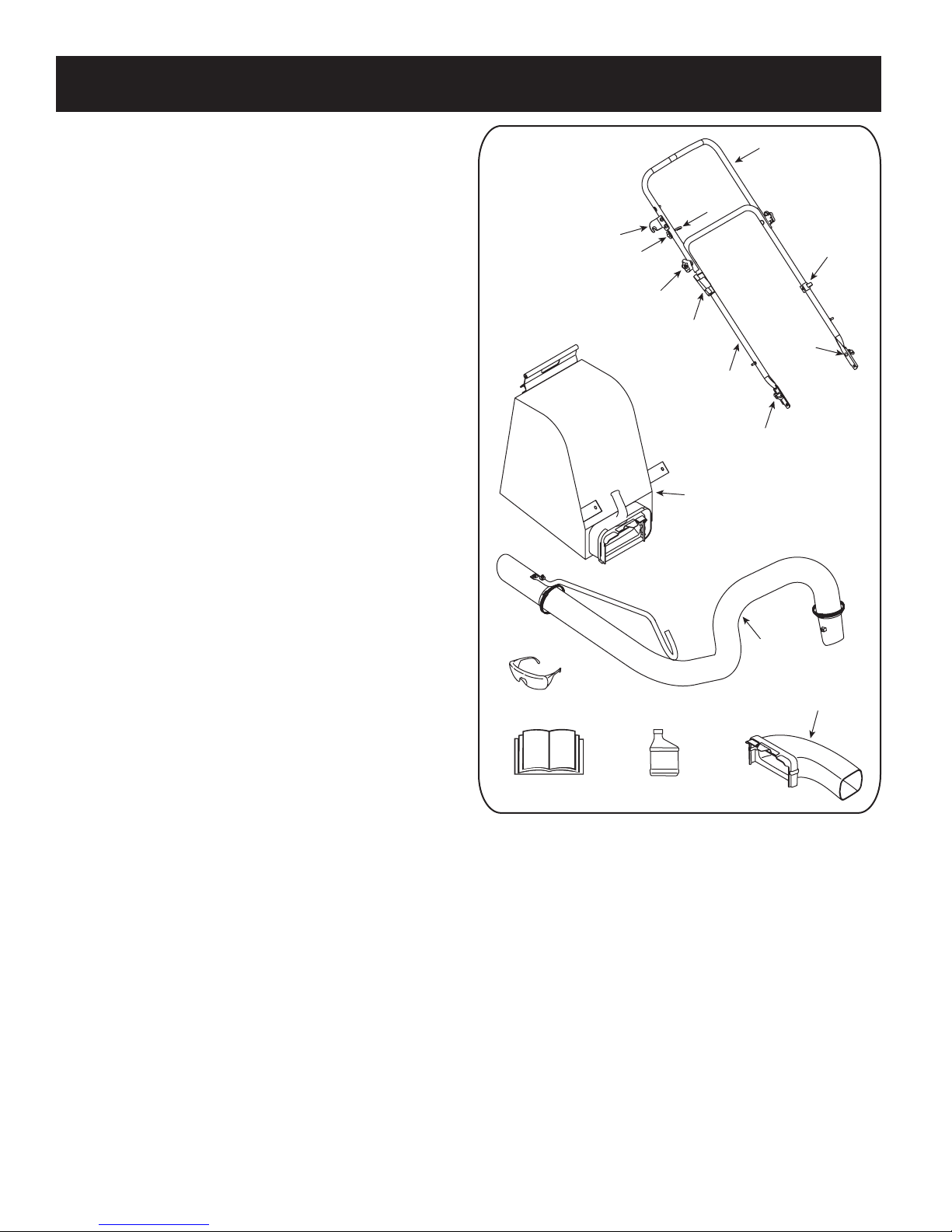
Loose Parts In Carton (See Figure 1)
• Upper and Lower Handle
• Hose Assembly
• Safety Glasses
• Engine Oil (May be located in bag)
• Bag
• Blower Chute
• Operator’s Manual
Figure 1
6
Page 7
ASSEMBLY
a
b
b
Rope Guide
c
d
a
b
c
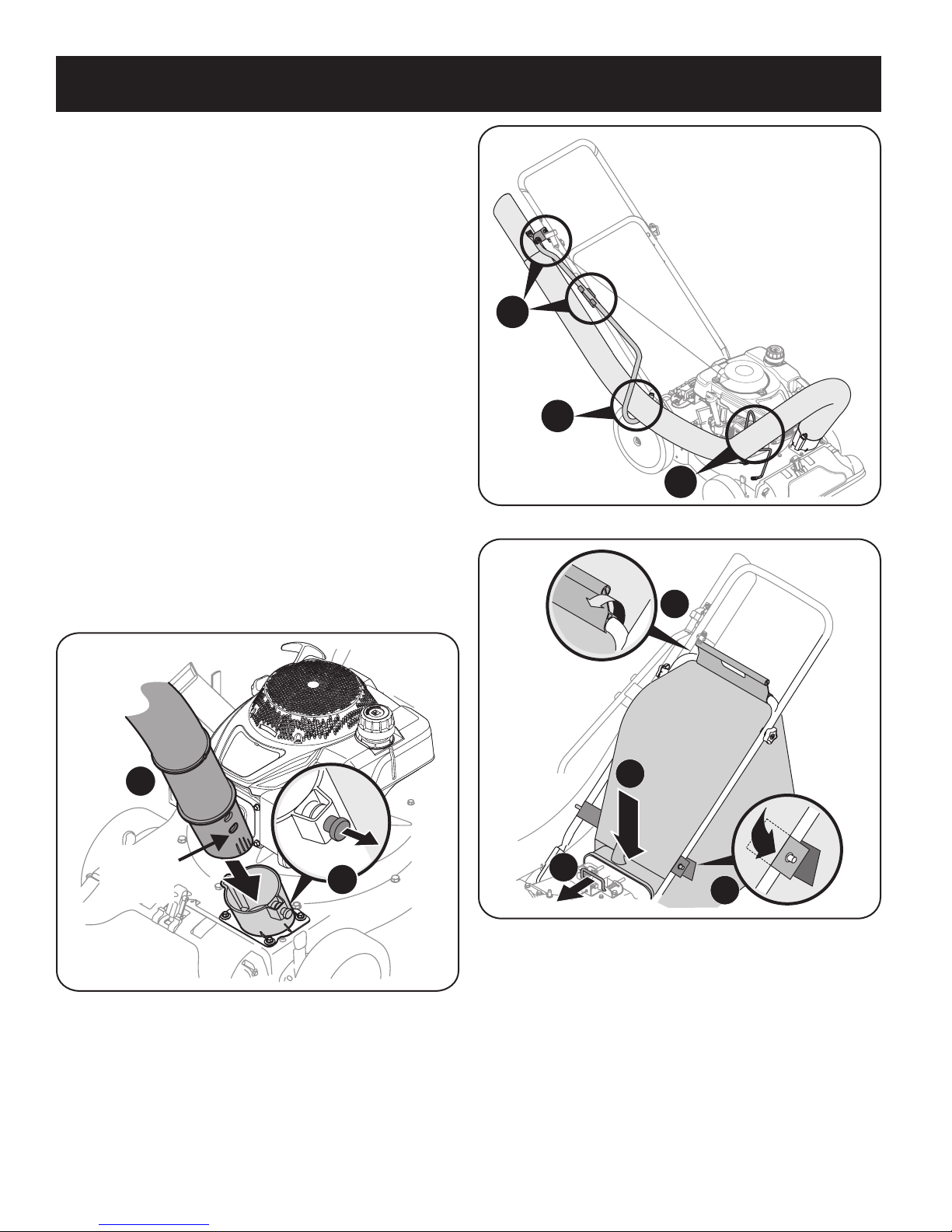
Attaching The Handle
1. Remove the hairpin clips from the handle brackets and remove the carriage
screws and wing nuts from the lower handle.
a. Place the bottom holes in lower handle over the pins on the handle
brackets and secure with hairpin clips. See Figure 2.
b. Insert carriage screws through upper hole in lower handle from the
inside and secure with wing nuts. See Figure 2.
c. Unfold the upper handle until it aligns with lower handle. Make sure
the rope guide is on the right side of upper handle. See Figure 3.
IM PORTANT: Make sure the cables are routed outside the lower handle. Also,
do not crimp the cables while lifting up the handles.
d. Secure the two handles by tightening the handle knobs (carriage
bolts must be seated properly into the handle). See Figure 3.
2. Loosen the wing nut that secures the rope guide to the right side of upper
handle.
a. Pull the starter rope out of the engine slowly. See Figure 4.
b. Slip the starter rope into the rope guide.
c. Tighten the wing nut. See Figure 4.
Figure 3
Figure 2
Figure 4
7
Page 8
ASSEMBLY
1
Align pin
with this
hole.
2
5
5
4
4
3
1
2
Attaching The Hose Assembly
1. Slide hose adapter of hose assembly into the base adapter located on the left
front of the Yard Vacuum. See Figure 5.
2. Pull spring loaded pin out on the base and align pin with the first hole
(closest to the end of the tube) in the hose adapter.
3. Release the pin to lock the hose in place.
4. Snap the hose handle first into the upper hose handle bracket and then into
the lower hose handle bracket. See Figure 6.
5. Lay hose tubing in curved end of handle next to chipper chute and into hose
cradle.
Attaching The Bag
1. Grasp bag handle with one hand and slide locking rod on mounting bracket
with other hand toward engine. Use the end of mounting bracket as leverage
when sliding the locking rod. See Figure 7.
2. Slip bag over the rim of the discharge opening and release locking rod to
secure bag in place.
3. Snap bag clip to the top of the lower handle.
4. Place the lower straps on the bag over the top of lower handle, hooking them
on the studs. See Figure 7.
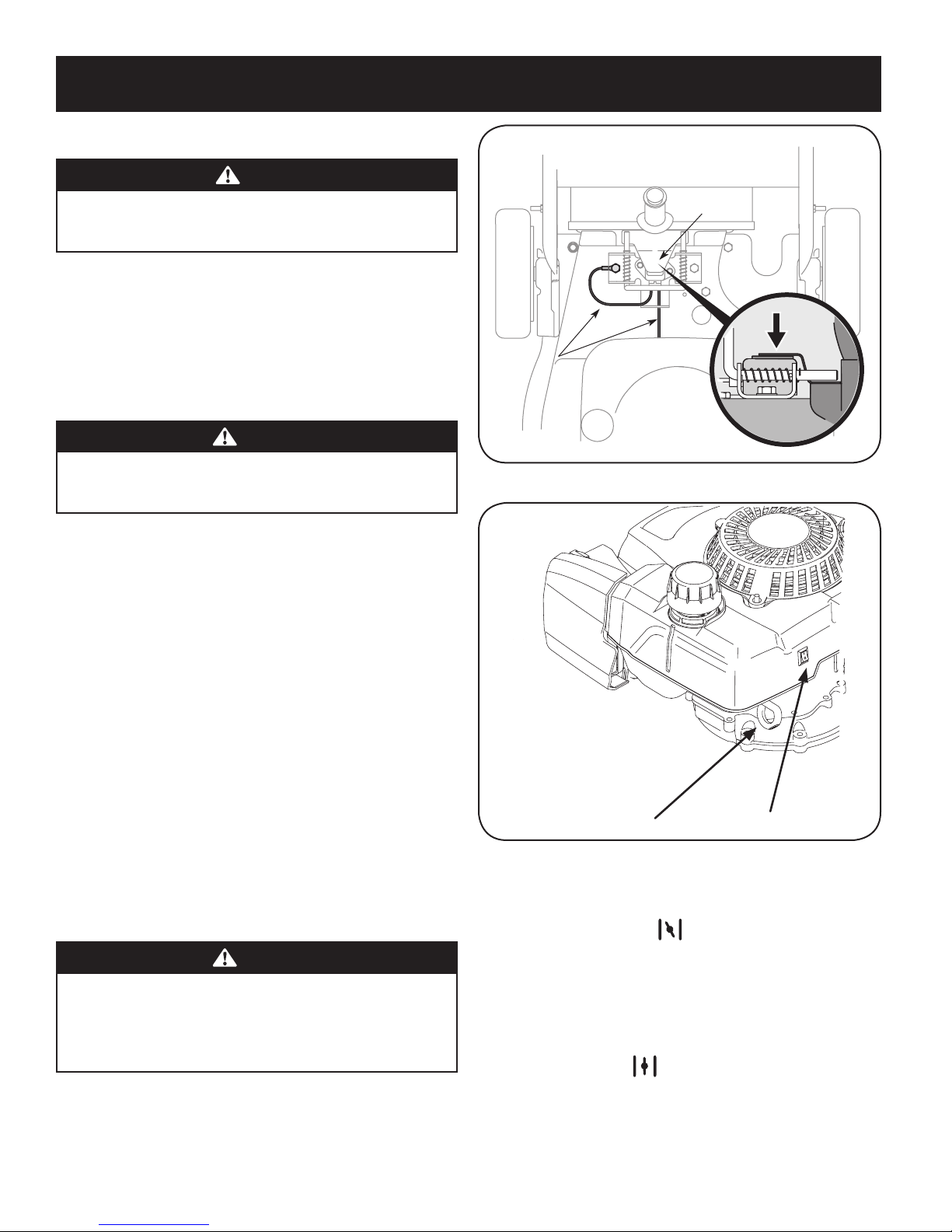
NOTE: The bag/chute switch button attached to the mounting bracket must
be fully depressed by the tip of front tab on bag handle when securing the
bag or engine will not start.
Figure 6
Figure 5
Figure 7
8
Page 9
ASSEMBLY
1
2
2
3
2
1
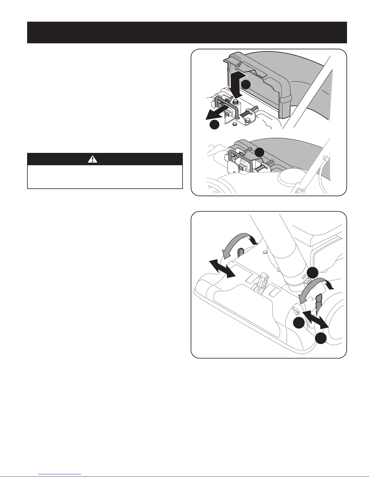
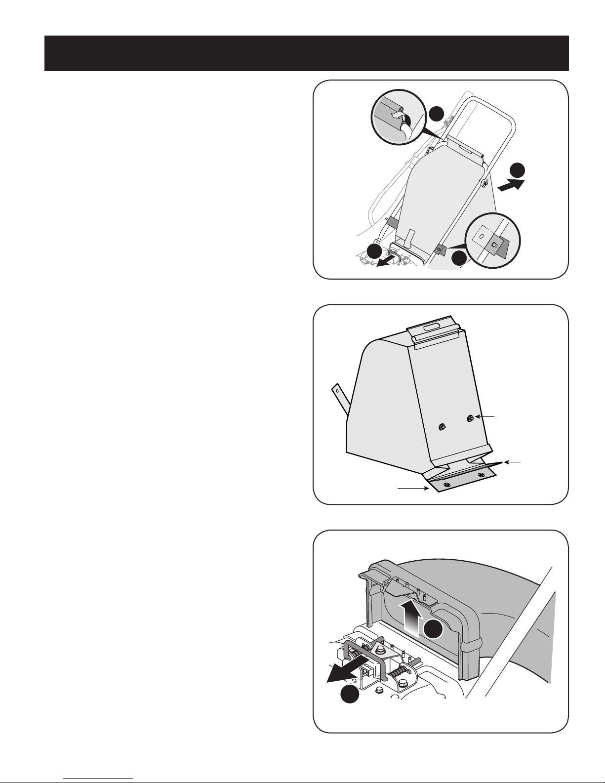
Attaching The Blower Chute
NOTE: The bag must be removed before installing the blower chute.
1. Grasp blower chute with one hand and slide locking rod on mounting bracket
with other hand toward engine. Use the end of mounting bracket as leverage
when sliding the locking rod. See Figure 8.
2. Slip blower chute over rim of discharge opening and release locking rod to
secure chute in place, as in Figure 8.
NOTE: The bag/chute switch button attached to the mounting bracket must
be fully depressed by the tip of front tab on the blower chute or engine will
not start.
IM PORTANT: Raise the nozzle height to the highest setting when using the
blower chute. Refer to nozzle height adjustment below.
WARNING
Always stop engine and disconnec t spark plug wire before performing any
maintenance or adjustments. Always wear safety glasses during operation
or while performing any adjustments or repairs.
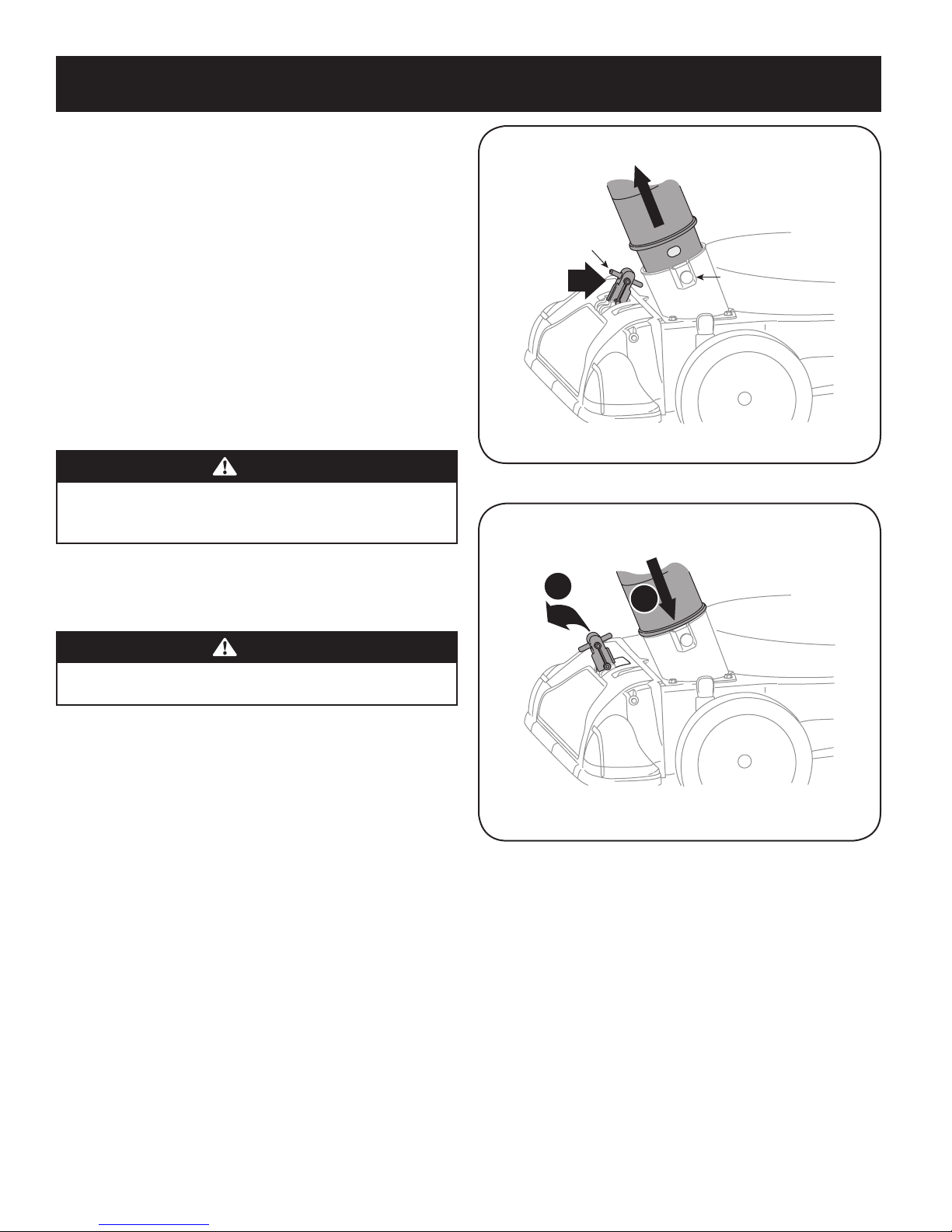
Nozzle Height Adjustment
The nozzle can be adjusted to any five positions, ranging from 5/8” to 4-1/8” ground
clearance. The nozzle height has to be adjusted according to yard conditions.
1. Depress nozzle height adjustment lever towards wheel. See Figure 9.
2. Move the height adjustment lever forward or backward to adjust the nozzle
upwards or downwards. Make sure both levers are in the same position.
3. Release lever towards deck.
NOTE: In general, raise the nozzle height to vacuum a thick layer of leaves
or to operate with the blower chute. Lower the nozzle height for smoother
surfaces.
Figure 8
Figure 9
9
Page 10
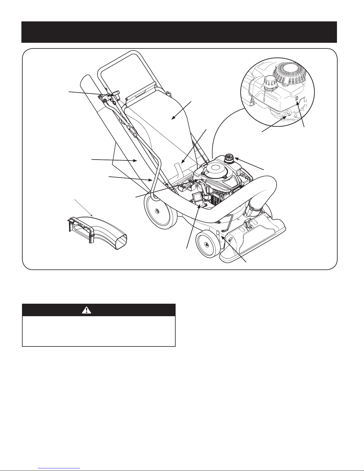
OPERATION
Nozzle Height
Adjustment Lever
Chipper Chute
Gasoline Fill
Oil Fill
Hose Handle
Hose Assembly
Recoil Starter
Bag
Bag Handle
Choke Control
ON/OFF Switch
Blower Chute
Now that you have set up your yard vacuum for operation, get acquainted with its
controls and features. These are described below and illustrated on this page. This
knowledge will allow you to use your new equipment to its fullest potential.
WARNING
The operation of any yard vacuum can result in foreign objects being
thrown into the eyes, which can damage your eyes severely. Always wear
the safety glasses provided with this unit or eye shields while operating or
performing any adjustments or repairs on it.
Chipper Chute
Allows twigs and small branches up to 1-1/2” in diameter to be fed into the impeller
for chipping. See Figure 10.
Nozzle Height Adjustment Lever
Used to adjust the nozzle ground clearance ranging approximately from 5/8” to
4-1/ 8”.
Craftsman Yard Vacuums conform to the safety standard of the American National Standards Institute (ANSI).
Figure 10
Nozzle
Yard waste such as leaves or pine needles can be vacuumed up through the nozzle
for shredding.
Hose Assembly
Used as an alternative to the nozzle to vacuum yard waste such as leaves or pine
needles in hard to reach places. See Figure 10.
Nozzle/ Hose Vac Lever
The nozzle/hose vac handle is located on top of the nozzle. Use it to switch vacuum
suction between the nozzle and the hose assembly.
Hose Handle
Used to guide hose assembly when vacuuming.
Bag Handle
Used to grasp bag in order to assist in attaching, removing, and emptying bag. See
Figure 10.
Meets ANSI Safety Standards
10
Page 11
OPERATION
G
J
H
Blower Chute
When attached to unit, the blower chute is used to discharge yard waste such as
leaves, pine needle, or small twigs across yard.
Choke Control
CHOKE RUN
The choke control is used to choke the carburetor and assist in starting the engine.
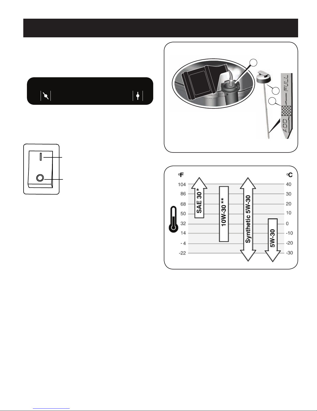
ON/OFF Switch
The ON/OFF switch controls the engine stop function. Turn the switch ON when
starting the engine and turn it to OFF when you want to shut it down.
ON (Ignition)
OFF
Gas And Oil Fill-Up
IM PORTANT: This unit is shipped without gasoline or oil in the engine. Be certain to
service engine with gasoline and oil as instructed in this section before starting or
running your machine.
Oil (one bottle shipped with unit)
First Time Use
1. Remove oil fill dipstick (G). See Figure 11.
2. With the yard vaccum on level ground, empty entire contents of oil bottle
provided into the engine oil fill (H).
3. Replace oil fill dipstick and tighten.
Subsequent Uses
Use 4-stroke motor oil that meets or exceeds the requirements for API service
category SF, SG, SH, SJ or higher. Always check the API service label on the oil
container to be sure it includes the letters SF, SG, SH, SJ or higher.
Outdoor temperatures determine the proper oil viscosity for the engine. Use the
chart shown in Figure 12 to select the best viscosity for the outdoor temperature
range expected.
Figure 11
Figure 12
* Below 40ºF (4ºC) the use of SAE 30 will result in hard starting.
** Above 80ºF (27ºC) the use of 10W-30 may cause increased oil consumption.
Check oil level more frequently.
1. Check the oil with the engine stopped and level.
2. Remove the oil fill dipstick and wipe it clean.
3. Insert and tighten the oil fill dipstick. Remove it to check the oil level. See
Figure 11.
4. If the oil level is near or below the lower limit mark on the dipstick, remove
the oil fill dipstick, and fill with the recommended oil to the upper limit
mark. Do not overf ill.
5. Reinstall the oil fill dipstick.
11
Page 12
OPERATION
Side View
Top View
Front Tab
Bag/Chute
Switch Wire
Choke Control
ON/OFF Switch
Gasoline
CAUTION
Do not use unapproved gasolines, such as E85. Do not mix oil in gasoline
or modify engine to run on alternate fuels. This will damage the engine
components and void the engine warranty.
Fuel must meet these requirements:
• Clean, fresh, unleaded gasoline.
• A minimum of 87 octane/87 AKI (91 RON).
• Gasoline with up to 10% ethanol (gasohol) is acceptable.
Refuel in a well-ventilated area with the engine stopped. If the engine has been
running, allow it to cool first. Never refuel the engine inside a building where
gasoline fumes may reach f lames or sparks.
WARNING
Gasoline is highly flammable and explosive, and you can be burned or
seriously injured when refueling. Stop engine and keep heat, sparks, and
flame away. Refuel only outdoors. Wipe up spills immediately.
If your equipment will be used on an infrequent or intermittent basis, please
refer to the Off Season Storage sec tion for additional information regarding fuel
deterioration.
NOTE: Fuel can damage paint and some types of plastic. Be careful not to spill fuel
when filling your fuel tank.
Never use stale or contaminated gasoline or an oil/gasoline mixture. Avoid getting
dirt or water in the fuel tank.
1. Remove the fuel tank cap.
2. Fill the fuel tank with fuel. To allow for expansion of the fuel, do not fill
above the bottom of the fuel tank neck. Do not overfill. Wipe up spilled fuel
before starting the engine.
3. Install the fuel tank cap and tighten it until it clicks.
4. Move yard vaccum at least 10 feet away from the fuel container/source and
site before starting the engine.
NOTE: Check the fuel level periodically to avoid running out of gasoline while
operating the yard vacuum. If the unit runs out of gas as it is chipping, it may be
necessary to unclog the discharge area before it can be restarted. Refer to SERVICE
AND MAINTENANCE sec tion.
Starting The Engine
Be sure no one other than the operator is standing near the yard vaccum
while starting engine or operating vacuum. Never run engine indoors
or in enclosed, poorly ventilated areas. Engine exhaust contains carbon
monoxide, an odorless and deadly gas. Keep hands, feet, hair and loose
clothing away from any moving parts on engine and yard vacuum.
IM PORTANT: The bag/chute switch button must be fully depressed by the tip of
front tab on bag handle or blower chute for engine to start. See Figure 13.
NOTE: Make sure bag/chute switch wire is connected to engine and grounded to
mounting bracket.
WARNING
Figure 13
Figure 14
1. Move ignition ON/OFF switch to ON. See Figure 14.
2. Pull out the choke control located on the engine. Pulling out the choke
control puts it into the CHOKE position.
NOTE: Use of the choke may not be necessary if the engine is warm or the air
temperature is high.
3. Pull the rope with a rapid, continuous, full arm stroke. Keep a firm grip on
the starter handle. Let the rope rewind slowly.
4. Repeat, if necessary, until engine star ts. As the engine warms up, move the
choke control to the RUN position.
12
Page 13
OPERATION
1
2
3
4
Buttons
Inner
Flap
Outer Flap
1
2
Stopping The Engine
1. Move engine switch to OFF position. See Figure 14.
To Empty Bag
1. Unhook bag straps from the lower handle.
2. Unsnap bag clip from the top of lower handle. See Figure 15.
3. Grasp bag handle with one hand and pull lock rod on mounting bracket with
other hand toward engine to release.
4. Lift bag off back of unit.
5. Twist the two buttons on the back of the bag to unlock and empty contents.
See Figure 16. Hold bag handle and bag clip while emptying the contents.
6. Compress bag opening and fold inner flap over opening.
7. Fold outer flap over inner flap and inser t buttons on the bag through metal
outlets. See Figure 16.
8. Twist the buttons to lock bag. Place bag back onto unit as instructed in the
ASSEMBLY section.
To Remove Blower Chute
1. Grasp blower chute with one hand and pull lock rod on mounting bracket
with other hand toward engine to release. Refer to Figure 17.
2. Remove blower chute from over the rim of the discharge opening.
Figure 15
Figure 16
Figure 17
13
Page 14
OPERATION
Vac Lever
Pin
1
2
Using The Nozzle Vacuum
1. Place nozzle/hose vac lever in the top position on the nozzle to vacuum
through nozzle. See Figure 18.
2. The spring loaded pin must be in the first hole (closest to the end of the
tube) of the hose adapter to operate the nozzle vac.
3. Place both hands on top of the upper handle and push unit over yard waste.
• Yard waste such as leaves and pine needles can be vacuumed up through the
nozzle for shredding. After material has been shredded by the flail blades
on the impeller assembly, it will be discharged into catcher bag or through
blower chute.
• Do not attempt to shred or chip any material other than vegetation found in
a normal yard (i.e. branches, leaves, twigs, etc.) Avoid fibrous plants such as
tomato vines or palm fronds until they are thoroughly dried out. Materials
such as stalks or heavy branches up to 1-1/2” in diameter may be fed into the
chipper chute.
WARNING
Do not attempt to shred, chip, or vacuum any material larger than
specified on the machine or in this manual. Personal injury or damage to
the machine could result.
IM PORTANT: The flail screen is located inside the housing in the discharge area. If
the flail screen becomes clogged, remove and clean as instructed in the Service &
Maintenance section. For best performance, it is also important to keep the chipper
blade sharp. See blade sharpening instructions in Service and Maintenance section.
WARNING
Do not at any time make any adjustments without first stopping engine
and disconnecting spark plug wire.
Using The Hose Assembly
1. Place nozzle/hose vac lever in the bottom position on the nozzle to redirect
vacuum to the hose assembly. See Figure 19.
2. The spring loaded pin must be in the second hole of the hose adapter to
operate the hose assembly.
3. Unhook the hose from upper handle bracket and grasp the hose handle to
guide while vacuuming yard waste such as leaves or pine needles in hard to
reach places.
Figure 18
Figure 19
14
Page 15
SERVICE AND MAINTENANCE
Electrode
0.020 in. (.51mm)
MAINTENANCE SCHEDULE
WARNING
Before performing any type of maintenance/service, disengage all controls
and stop the engine. Wait until all moving parts have come to a complete
stop. Disconnec t spark plug wire and ground it against the engine to
prevent unintended starting. Always wear safety glasses during operation
or while performing any adjustments or repairs.
Interval Item Service Service Log
Each Use and every 5 hours 1. Engine oil level
2. Loose or missing hardware
3. Unit and engine.
1st 5 hours 1. Engine oil 1. Change
Annually or 25 hours 1. Air filter
2. Control linkages, pivots, & wheels
3. Underside of deck
Annually or 50 hours 1. Engine oil 1. Change
Annually 1. Spark plug
2. Air Filter
Before Storage 1. Fuel system 1. Run engine until it stops from lack of fuel, or
† Clean more often under dusty conditions or when airborne debris is present.
Follow the maintenance schedule given below. This chart describes service
guidelines only. Use the Service Log column to keep track of completed
maintenance tasks. To schedule service by an authorized dealer, call Craftsman at
1-88 8-331-4569.
1. Check
2. Tighten or replace
3. Clean
1. Clean
2. Lube with light oil
3. Clean
1. Replace
2. Replace
add stabilizer to a full tank of fresh fuel prior
to storage.
WARNING
Always stop engine and disconnec t spark plug wire before performing any
maintenance or adjustments. Always wear safety glasses during operation
or while performing any adjustments or repairs.
General Recommendations
• Always observe safety rules when performing any maintenance.
• The warranty on this yard vacuum does not cover items that have been
subjected to operator abuse or negligence. To receive full value from
warranty, operator must maintain the equipment as instructed here.
• Some adjustments will have to be made periodically to maintain your unit
properly.
• Periodically check all fasteners and make sure these are tight.
Engine Maintenance
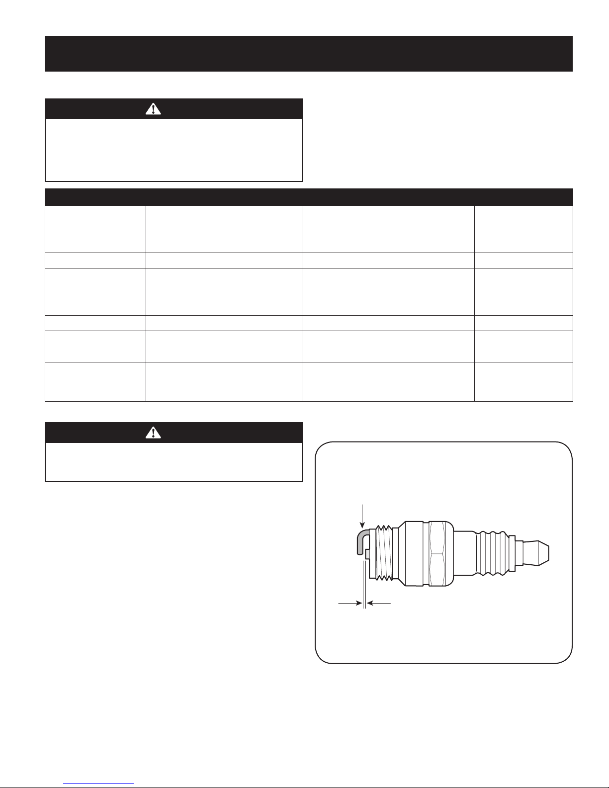
Spark Plug
Clean spark plug and reset the electrode gap to 0.020” at least once a season;
replace annually.
1. Disconnect the cap from the spark plug, and remove any dirt from the spark
plug area.
2. Use the proper size spark plug wrench to remove the spark plug.
3. Check the gap with a wire gauge. See Figure 20. Spark plug gap should be
0.020 in (0.51 mm). If necessary, reset the gap.
Figure 20
4. Install and tighten the spark plug to the recommended torque (180 lb-in [20
Nm]).
5. Attach the spark plug cap to the spark plug.
15
Page 16

SERVICE AND MAINTENANCE
Oil Fill/ Dipstick
Muffler
Air filter
Air Filter
A dirty air f ilter will restrict air flow to the carburetor and cause poor engine
performance. Inspect the filter each time the engine is operated. You will need to
clean the filter more frequently if you operate the engine in very dusty areas.
Clean the air filter every 25 hours of operation or once a season. Replace the air filter
annually.
WARNING
Never start or run the engine with the air filter assembly or the air filter
removed.
NOTE: Do not use pressurized air or solvents to clean the filter. Pressurized air can
damage the filter and solvents will dissolve the f ilter.
1. Press the two tabs that hold the cover and tilt plastic housing cover on side of
engine down. See Figure 21.
2. Remove air filter from plastic housing cover.
3. To loosen debris, gently tap the filter on a hard surface. If the filter is
excessively dirty, replace with a new filter.
4. Insert cover’s tabs into slots in bottom of base.
5. Tilt cover up into place and secure with fastener.
Figure 21
Check Engine Oil
Check oil level before each operation. Be sure oil level is maintained.
1. Check the oil with the engine stopped and level.
2. Remove the oil fill dipstick and wipe it clean.
3. Insert and tighten dipstick. Remove it to check the oil level.
4. If the oil level is near or below the lower limit mark on the dipstick, remove
the oil filler cap/dipstick, and fill with the recommended oil to the upper
limit mark. Do not overfill.
5. Reinstall the oil fill dipstick.
Change Engine Oil
WARNING
Gasoline and its vapors are extremely flammable and explosive. Fire or
explosion can cause severe burns or death.
Change engine oil after the first five hours of operation, and every f ifty hours or
once a season thereafter.
WARNING
When you drain the oil from the top oil f ill tube, the fuel tank must be
empty or fuel can leak out and result in a fire or explosion. To empty the
fuel tank, run the engine until it stops from lack of fuel.
1. With engine off but still warm, disconnect the spark plug wire and keep it
away from the spark plug.
2. Place a suitable container next to the engine to catch the used oil.
3. Remove the oil fill dipstick and drain the oil into the container by tipping the
engine toward the oil filler neck. See Figure 22.
Figure 22
CAUTION
Used oil is a hazardous waste product. Dispose of used oil properly. Do not
discard with household waste. Check with your local authorities or Sears
Service Center for safe disposal/recycling facilities.
4. With the engine in a level position, fill to the upper limit mark on the dipstick
with the recommended oil.
CAUTION
Running the engine with a low oil level can cause engine damage.
5. Reinstall the oil fill dipstick securely.
16
Page 17

SERVICE AND MAINTENANCE
Clean Engine
• Daily or before every use, clean grass, chaff or accumulated debris from
engine. Keep linkage, spring, and controls clean. Keep area around and
behind muffler free of any combustible debris.
• Keeping engine clean allows air movement around engine.
• Engine parts should be kept clean to reduce the risk of overheating and
ignition of accumulated debris.
CAUTION
Do not use water to clean engine parts. Water could contaminate fuel
system. Use a brush or dry cloth.
Lubrication
Wheels
Place a few drops of SAE 30 oil on each shoulder screw once a season.
Nozzle Height Adjustment Levers
Lubricate nozzle height adjustment levers with light oil.
Locking Rod
Lubricate the lock rod and compression springs which attach to the mounting
bracket.
Figure 23
Nozzle/Hose Vac Lever
Lubricate the nozzle/hose vac lever on top of the nozzle once a season with light oil.
Cleaning Equipment
Clean underside of the yard vacuum once a season to prevent build-up of debris.
Follow steps below for this job:
1. Disconnect and ground spark plug wire. Empty the fuel tank by running
engine until tank is dry.
2. Tip the yard vacuum so that it rests on its side, keeping the muf fler side
down. Hold yard vacuum firmly.
3. Scrape and clean the underside of the deck and nozzle with a suitable tool.
Do not spray with water.
IM PORTANT: Do not use a pressure washer or garden hose to clean your unit.
These may cause damage to bearings, or the engine. The use of water will result in
shortened life and reduce serviceability.
4. Put the yard vacuum back on its wheels on the ground.
Cleaning The Flail Screen
If the discharge area becomes clogged, remove the flail screen and clean area as
follows:
1. Stop the engine. Make certain the chipper/shredder vacuum has come to a
complete stop.
2. Before unclogging the discharge chute, disconnect and ground the spark
plug wire.
3. Remove the vacuum bag or blower chute from the unit as instructed in the
OPERATION section to obtain access to flail screen.
Figure 24
4. Remove the three self tapping screws securing the belt cover, and remove
belt cover. See Figure 23.
5. Remove self tapping screw on right side of unit that attaches to the flail
screen. See Figure 24.
17
Page 18

SERVICE AND MAINTENANCE
Hub Cap
Thrust Washer
Bell Washer
Pivot Arm Assembly
Front Support Brace and Lock Nut
Shoulder Screw
Lock Nut
Wheel
Wave
Washer
6. Remove hex screw on top of rear housing near mounting bracket and the
flange lock nut that secures flail screen. See Figure 24.
7. Remove and clean the screen by scraping or washing with water. See Figure
25 below.
8. Reinstall the screen.
WARNING
Before performing any type of maintenance on the machine, wait for
all parts to stop moving and disconnect and ground the spark plug wire.
Failure to follow this instruction could result in personal injury or property
damage.
Sharpening Or Replacing Chipper Blade
NOTE: Before tipping the unit, empty the fuel tank by running engine until tank is
dry, and empty the oil reservoir as described in To Drain Oil.
1. Disconnect and ground the spark plug wire.
2. Remove bag assembly or blower chute.
3. Remove the three hex cap screws holding the chipper chute to the upper
housing. See Figure 26.
4. Remove the front hubcaps, flange lock nuts, front wheels, and wave washers
that attach to the pivot arm assemblies. See Figure 27.
5. Remove the shoulder screws, thrust washers, and bell washers that go
through the pivot arms to the front support brace. The front suppor t brace
and lock nut can be removed at this time as well.
6. Remove the four screws on the upper housing that secure the nozzle cover.
See Figure 28.
Figure 25
Figure 26
18
Figure 27
Figure 28
Page 19

SERVICE AND MAINTENANCE
Black
Plastic
Nozzle
Shoulder Screws
Flat Head Cap Screws
Chipper Blade
Nuts
Impeller
7. Carefully tilt and support the unit up to provide access underneath to the
nozzle mounting hardware and impeller. Remove the three shoulder bolts
securing the black plastic lower flail housing to the lower housing. Refer to
Figure 29.
8. Tilt top of black plastic lower flail housing toward the engine to remove.
9. Using a 3/16” allen wrench, remove the flat head cap screws that hold the
chipper blade to the impeller. These screws are accessible through the
opening created when the chipper chute was removed earlier. See Figure 30.
10. The nuts on the flat head cap screws can be reached from underneath using
a 1/2-inch socket, universal, and extension. See Figure 31.
11. Replace or sharpen chipper blade. The blade can be sharpened with a f ile or
on a grinding wheel.
WARNING
The chipper blade is sharp. When sharpening blade, wear leather work
gloves to protect your hands and follow the original angle of grind.
12. Reassemble by performing the previous steps in the opposite order and
manner of removal.
NOTE: Tighten blade screws to 210 - 250 in-lbs. Make certain chipper blade is
reassembled with the sharp edge facing upward.
Figure 30
Figure 29
Figure 31
19
Page 20

OFF-SEASON STORAGE
WARNING
Never store yard vacuum with fuel in tank indoors or in poorly ventilated
areas where fuel fumes may reach an open flame, spark, or pilot light as on
a furnace, water heater, clothes dryer, or gas appliance.
Preparing The Engine
For engines stored over 30 days:
• To prevent gum from forming in fuel system or on carburetor parts, run
engine until it stops from lack of fuel or add a gasoline additive to the gas
in the tank. If you use a gas additive, run the engine for several minutes to
circulate the additive through the carburetor—after which the engine and
fuel can be stored up to 24 months.
• While engine is still warm, change the oil.
• Clean engine of surface debris.
Preparing The Yard Vacuum
• Clean and lubricate yard vacuum thoroughly as described in the lubrication
instructions.
• Do not use a pressure washer or garden hose to clean your unit.
• Refer to Preparing the Engine for correct engine storage instructions.
• Store unit in a dry, clean area. Do not store next to corrosive materials, such
as fertilizer.
When storing any type of power equipment in a poorly ventilated or metal storage
shed, care should be taken to rust-proof the equipment. Using a light oil or silicone,
coat the equipment, especially cables and all moving parts of your yard vaccum
before storage.
20
Page 21

TROUBLESHOOTING
WARNING
Disconnect the spark plug wire and ground it against the engine to prevent
unintended starting. Before performing any type of maintenance/service,
disengage all controls and stop the engine. Wait until all moving parts
have come to a complete stop. Always wear safety glasses during operation
or while performing any adjustments or repairs.
This section addresses minor service issues. To schedule repair by an authorized service dealer call Craftsman at 1-888-331-4569.
Problem Cause Remedy
Engine Fails to start 1. Ignition ON/OFF switch in OFF position.
2. Choke control not in CHOKE position.
3. Spark plug boot disconnec ted.
4. Faulty spark plug.
5. Fuel tank empty or stale fuel.
6. Blocked fuel line.
7. Cannot pull recoil starter cord.
8. Safety switch not depressed.
9. Safety switch wire is not connec ted to engine or not
properly grounded.
Engine runs erratic 1. Unit running on CHOKE.
2. Spark plug boot loose.
3. Stale fuel.
4. Water or dirt in fuel system.
5. Dirty air cleaner.
6. Low engine RPM.
7. Blocked fuel line.
1. Move Ignition ON/OFF switch to ON position.
2. Move choke control to CHOKE position.
3. Connect wire to spark boot.
4. Clean, adjust gap, or replace.
5. Fill tank with clean, fresh gasoline.
6. Call Craftsman at 1-888-331-4569 to have fuel line cleaned.
7. Obstruction lodged in impeller. Disconnect spark plug wire and
remove lodged object.
8. Safety switch must be depressed by the front tab on the bag
handle when securing the bag.
9. Connect safety switch wire to engine connector and ground to
mounting bracket.
1. Move choke control to RUN position.
2. Connect and tighten spark plug boot.
3. Fill tank with clean, fresh gasoline.
4. Run engine until it stops from lack of fuel. Refill with f resh fuel.
5. Refer to Air Cleaner in Engine Maintenance sec tion.
6. Always run engine at full throttle.
7. Call Craftsman at 1-888-331-4569 to have fuel line cleaned.
Engine overheats 1. Engine oil level low.
2. Air flow restricted.
Occasional skips (hesitates) 1. Spark plug gap too close. 1. Adjust gap. Refer to Spark Plug in Engine Maintenance section.
1. Fill crankcase with proper oil.
2. Clean area around and on top of engine.
21
Page 22

TROUBLESHOOTING
Problem Cause Remedy
Idles poorly 1. Spark plug fouled, faulty, or gap too wide.
2. Dirty air cleaner.
Excessive vibration 1. Loose par ts or damaged impeller. 1. Stop engine immediately and disconnect spark plug wire. Call
Unit does not discharge 1. Discharge area clogged.
2. Foreign object lodged in impeller.
3. Low engine RPM.
4. Vacuum bag is full.
Rate of discharge slows
considerably or composition of
discharged material changes.
1. Low engine RPM.
2. Chipper blade dull.
1. Reset gap or replace spark plug.
2. Refer to Air Cleaner in Engine Maintenance section.
Craftsman at 1-888-331-4569 for inspection and repair
1. Stop engine immediately and disconnect spark plug wire. Clean
flail screen and inside of discharge opening.
2. Stop engine and disconnect spark plug wire. Remove lodged
object.
3. Always run engine at full throttle.
4. Empty bag.
1. Always run engine at full throttle.
2. Refer to Sharpening or Replacing Chipper Blade section, or call
Craftsman at 1-888-331-4569 for chipper blade ser vice.
22
Page 23

(This page applicable in the U.S.A. and Canada only.)
Sears Brands Management Corporation (Sears), the California Air Resources Board (CARB)
and the United States Environmental Protection Agency (U.S. EPA)
Emission Control System Warranty Statement (Owner’s Defect Warranty Rights and Obligations)
EMISSION CONTROL WARRANTY COVERAGE IS APPLICABLE TO CERTIFIED ENGINES
PURCHASED IN CALIFORNIA IN 1995 AND THEREAFTER, WHICH ARE USED IN CALIFORNIA,
California and United States Emission Control Defects Warranty Statement
The California Air Resources Board (CARB), U.S. EPA and Sears are pleased to explain the
Emission Control System Warranty on your model year 2000 and later small of f-road
engine (SORE). In California, new small off-road engines must be designed, built and
equipped to meet the State’s stringent anti-smog standards. Elsewhere in the United
States, new non-road, spark-ignition engines certified for model year 1997 and later
must meet similar standards set forth by the U.S. EPA. Sears must warrant the emission
Sears Emission Control Defects Warranty Coverage
Small off-road engines are warranted relative to emission control parts defects for a
period of one year, subject to provisions set forth below. If any covered part on your
Owner’s Warranty Responsibilities
As the small off-road engine owner, you are responsible for the performance of the
required maintenance listed in your Operating and Maintenance Instructions. Sears
recommends that you retain all your receipts covering maintenance on your small
off-road engine, but Sears cannot deny warranty solely for the lack of receipts or for
your failure to ensure the per formance of all scheduled maintenance. As the small
off-road engine owner, you should however be aware that Sears may deny you warranty
coverage if your small off-road engine or a part has failed due to abuse, neglec t,
Sears Emission Control Defects Warranty Provisions
The following are specific provisions relative to your Emission Control Defects Warranty
Coverage. It is in addition to the Sears engine warranty for non-regulated engines found
in the Operating and Maintenance Instructions.
1. Warranted Parts
Coverage under this warranty extends only to the parts listed below (the
emission control systems parts) to the extent these parts were present on the
engine purchased.
a. Fuel Metering System
• Cold start enrichment system
• Carburetor and internal parts
• Fuel Pump
b. Air Induction System
• Air cleaner
• Intake manifold
c. Ignition System
• Spark plug(s)
• Magneto ignition system
d. Catalyst System
• Catalytic converter
• Exhaust manifold
• Air injection system or pulse valve
e. Miscellaneous Items Used in Above Systems
• Vacuum, temperature, position, time sensitive valves and switches
• Connectors and assemblies
2. Length of Coverage
Sears warrants to the initial owner and each subsequent purchaser that the
Warranted Parts shall be free from defects in materials and workmanship which
caused the failure of the Warranted Parts for a period of one year from the date
the engine is delivered to a retail purchaser.
AND TO CERTIFIED MODEL YEAR 1997 AND LATER ENGINES WHICH ARE PURCHASED AND
USED ELSEWHERE IN THE UNITED STATES (AND AFTER JANUARY 1, 2001 IN CANADA).
control system on your engine for the periods of time listed below, provided there has
been no abuse, neglect or improper maintenance of your small off-road engine. Your
emission control system includes parts such as the carburetor, air cleaner, ignition
system, muffler and catalytic converter. Also included may be connectors and other
emission related assemblies. Where a warrantable condition exists, Sears will repair
your small off-road engine at no cost to you including diagnosis, parts and labor.
engine is defective, the part will be repaired or replaced by Sears.
improper maintenance or unapproved modifications. You are responsible for presenting
your small off-road engine to an Authorized Sears Service Dealer as soon as a problem
exists. The undisputed warranty repairs should be completed in a reasonable amount
of time, not to exceed 30 days. If you have any questions regarding your warranty rights
and responsibilities, you should contact a Sears Service Representative at 1-800-469-
4663. The emission warranty is a defects warranty. Defects are judged on normal engine
performance. The warranty is not related to an in-use emission test.
3. No Charge
Repair or replacement of any Warranted Part will be performed at no charge to
the owner, including diagnostic labor which leads to the determination that a
Warranted Part is defective, if the diagnostic work is performed at an Authorized
Sears Service Dealer. For emissions warranty service contact your nearest
Authorized Sears Service Dealer as listed in the “Yellow Pages” under “Engines,
Gasoline,” “Gasoline Engines,” “Lawn Mowers,” or similar category.
4. Claims and Coverage Exclusions
Warranty claims shall be filed in accordance with the provisions of the Sears
Engine Warranty Policy. Warranty coverage shall be excluded for failures of
Warranted Parts which are not original Sears parts or because of abuse, neglect
or improper maintenance as set forth in the Sears Engine Warranty Policy. Sears
is not liable to cover failures of Warranted Parts caused by the use of add-on,
non-original, or modified parts.
5. Maintenance
Any Warranted Part which is not scheduled for replacement as required
maintenance or which is scheduled only for regular inspec tion to the effect of
“repair or replace as necessary” shall be warranted as to defects for the warranty
period. Any Warranted Part which is scheduled for replacement as required
maintenance shall be warranted as to defects only for the period of time up
to the first scheduled replacement for that part. Any replacement part that is
equivalent in performance and durability may be used in the per formance of
any maintenance or repairs. The owner is responsible for the performance of
all required maintenance, as defined in the Sears Operating and Maintenance
Instructions.
6. Consequential Coverage
Coverage hereunder shall extend to the failure of any engine components caused
by the failure of any Warranted Part still under warranty.
073808 Rev. A
Page 24

ÍNDICE
Declaración de garantía .......................Página 24
Prácticas operación seguras ...................Página 25
Desembalaje ..................................Página 29
Montaje ......................................Página 30
Operación ....................................Página 33
Servicio y Mantenimiento .....................Página 38
Almacenamiento fuera de temporada .........Página 44
Solución de problemas ........................Página 45
Número de servicio .................. Cubierta posterior
DECLARACIÓN DE GARANTÍA
CRAFTSMAN DE GARANTÍA LIMITADA
POR DOS AÑOS a partir de la fecha de compra, este producto está garantizado contra cualquier defecto de material o mano de obra.
CON EL COMPROBANTE DE VENTA, un producto defectuoso recibirá la reparación. Si el producto no puede ser reparado recibirá sustitución gratuita.
Para obtener información detallada cobertura de la garantía para obtener la reparación, visite el sitio web: www.craftsman.com/warranty
Esta garantía cubre los defectos SOLO de materiales y fabricación. La garantía no incluye:
• Elementos reutilizables que pueden gastarse por el uso normal dentro del periodo de garantía, tales como las cuchillas, bujías, filtro de aire, pantalla de
desgranado y una bolsa.
• Producto daños resultantes de los intentos del usuario de modificación del producto, reparación o causados por accesorios de productos.
• Reparaciones necesarias debido al accidente o por no operar o mantener el producto según las instrucciones provistas.
• El mantenimiento preventivo o reparaciones necesarias debido a una mezcla incorrecta de combustible, combustible contaminado o pasado.
Esta garantía es inválida si este producto se utiliza al mismo tiempo la prestación de servicios comerciales o si se alquila a otra persona.
Esta garantía le otorga derechos legales específicos, y usted también puede tener otros derechos que varían de estado a estado.
Sears Brands Management Corporation, Hoffman Estates, IL 60179
NÚMERO DE MODELOESPECIFICACIONES DEL PRODUCTO
Aceite del motor: SAE 10w-30
Combustible: Gasolina sin plomo
Motor: Craftsman
Número de modelo _____________________________
Número de serie ________________________________
Fecha de compra _______________________________
Registre el número de modelo, número de serie y fecha
de compra más arriba.
© Sears Brands, LLC
24
Page 25

INSTRUCCIONES DE SEGURIDAD
ADVERTENCIA
La presencia de este símbolo indica que se trata de instrucciones
importantes de seguridad que se deben respetar para evitar poner en
peligro su seguridad personal y/o material y la de otras personas. Lea y siga
todas las instrucciones de este manual antes de poner en funcionamiento
esta máquina. Si no respeta estas instrucciones podría provocar lesiones
personales. Cuando vea este símbolo, ¡preste atención a la advertencia!
ADVERTENCIA
PROPOSICIÓN 65 DE CALIFORNIA
El escape del motor de este producto, algunos de sus componentes y
algunos componentes del vehículo contienen o liberan sustancias químicas
que el estado de California considera que pueden producir cáncer, defectos
de nacimiento u otros problemas reproductivos.
CAPACITACIÓN
• Lea, entienda y cumpla todas las instrucciones incluidas en la máquina y en
los manuales antes de montarla y utilizarla. Guarde este manual en un lugar
seguro para consultas futuras y regulares, así como para solicitar repuestos.
• Lea el Manual del Operador y siga todas las advertencias e instrucciones de
seguridad. El fracaso de hacer así puede causar la herida seria al operador y/o
personas presentes.
• Familiarícese con todos los controles y su operación adecuada. Sepa cómo
detener la máquina y cómo desengranar los controles rápidamente.
• No permita nunca que los niños menores de 16 años utilicen esta
máquina. Los niños de 16 años y más mayores deben leer y comprender
las instrucciones de operación y las reglas de seguridad contenidas en este
manual, y también deben ser capacitados y estar supervisados por uno de
los padres.
• Nunca permita que los adultos operen esta máquina sin recibir antes la
instrucción apropiada.
• Mantenga a los transeúntes, ayudantes, mascotas y niños al menos a 75 pies
de la máquina mientras está operando. Detenga la máquina si alguien entra
en la zona.
• Nunca encienda un motor en espacios cerrados o en una zona con poca
ventilación. El escape del motor contiene monóxido de carbono, un gas
inodoro y letal.
• No ponga las manos o los pies cerca de las piezas rotatorias o en las cámaras
de alimentación ni en la abertura de descarga. El contacto con el motor
rotatorio puede producir la amputación de dedos, manos o pies.
• Nunca trate de destapar la toma de alimentación o la aber tura de descarga,
ni trate de sacar o vaciar la bolsa de la aspiradora, ni de revisar y reparar la
máquina mientras el motor está en marcha. Apague el motor y espere hasta
que todas las piezas móviles se hayan detenido por completo. Desconecte el
cable de la bujía y póngalo de manera que haga masa contra el motor.
PELIGRO
Esta máquina fue construida para ser operada de acuerdo con las reglas
de seguridad contenidas en este manual. Al igual que con cualquier tipo
de equipo motorizado, un descuido o error por parte del operador puede
producir lesiones graves. Esta máquina es capaz de amputar manos y pies
y de arrojar objetos con gran fuerza. De no respetar las instrucciones de
seguridad siguientes se pueden producir lesiones graves o la muerte.
ADVERTENCIA
Su responsabilidad—Restrinja el uso de esta máquina motorizada
a las personas que lean, comprendan y respeten las advertencias e
instrucciones que aparecen en este manual y en la máquina.
¡GUARDE ESTAS INSTRUCCIONES!
PREPARATIVOS
• Inspeccione minuciosamente el área donde utilizará el equipo. Retire
todas las piedras, botellas, latas u otros objetos extraños que puedan ser
levantados o arrojados causando lesiones personales o daños a la máquina.
• Para protegerse los ojos utilice siempre anteojos o antiparras de seguridad
mientras opera la máquina o mientras la ajusta o repara. Los objetos
arrojados que rebotan pueden lesionar gravemente la vista.
• Utilice zapatos de trabajo resistentes, de suela fuer te, así como pantalones
y camisas ajustados. Las prendas sueltas o las alhajas pueden quedar
atrapadas en las piezas móviles. Nunca utilice la máquina descalzo o con
sandalias. Utilice guantes de trabajo de cuero cuando alimente material por
el canal de la cortadora.
• Antes de encender la máquina controle que todos los pernos y tornillos estén
bien ajustados para comprobar que la máquina se encuentra en condiciones
seguras de operación. Además, realice una inspección visual de la máquina a
intervalos frecuentes para controlar si la misma está dañada.
• Mantenga o reemplace las etiquetas de seguridad e instrucciones según sea
necesario.
25
Page 26

INSTRUCCIONES DE SEGURIDAD
Manejo seguro de la gasolina
Para evitar lesiones personales o daños materiales sea sumamente cuidadoso al
manipular la gasolina. La gasolina es altamente inflamable y sus vapores pueden
causar explosiones. Se puede lesionar gravemente si derrama gasolina sobre usted
o sobre la ropa ya que se puede encender. Lávese la piel y cámbiese de ropa de
inmediato.
• Utilice sólo recipientes para gasolina autorizados.
• Nunca llene los contenedores en el interior de un vehículo o camión o caja de
camioneta con recubrimientos plásticos. Coloque siempre los recipientes en
el piso y lejos del vehículo antes de llenarlos.
• Retire el equipo a gasolina del camión o remolque y llénelo en el piso. Si esto
no es posible, entonces llene dicho equipo en un remolque con un recipiente
portátil, en vez de desde un dispensador de gasolina.
• Mantenga la boquilla de llenado en contacto con el borde de la entrada del
tanque de gasolina o contenedor en todo momento hasta que esté lleno. No
utilice un dispositivo para abrir/cerrar la boquilla.
• Apague todos los cigarrillos, cigarros, pipas y otras fuentes de combustión.
• Nunca cargue combustible en la máquina en un espacio cerrado.
• Nunca saque la tapa del gas ni agregue combustible mientras el motor está
caliente o en marcha. Deje que el motor se enfríe por lo menos dos minutos
antes de volver a cargar combustible.
• Nunca recargue el tanque de combustible. Llene el tanque no más de 1/2
pulgada por debajo de la base del cuello del filtro para dejar espacio para la
dilatación del combustible.
• Vuelva a colocar la tapa de la gasolina y ajústela bien.
• Limpie la gasolina derramada sobre el motor y el equipo. Traslade la
máquina a otra zona. Espere 5 minutos antes de encender el motor.
• Nunca almacene la máquina o el recipiente de combustible en un espacio
cerrado donde haya fuego, chispas o luz piloto (por ejemplo, hornos,
calentadores de agua, calefactores, secadores de ropa, etc.)
• Para reducir el riesgo de incendio mantenga la máquina limpia de pasto,
hojas y de acumulación de otros desechos. Limpie los derrames de aceite o
combustible y saque todos los desechos embebidos con combustible.
FUNCIONAMIENTO
• No ponga las manos o los pies cerca de las piezas rotatorias o en las cámaras
de alimentación ni en la abertura de descarga. El contacto con el motor
rotatorio puede producir la amputación de dedos, manos o pies.
• Antes de encender la máquina compruebe que el canal de la cortadora, la
toma de alimentación y la cámara de corte están vacías y sin desechos.
• Inspeccione minuciosamente todo el material que desea triturar y saque
los objetos metálicos, piedras, botellas, latas u otros objetos extraños que
pueden ocasionar lesiones o dañar la máquina.
• Si el motor golpea un objeto extraño o si la máquina empieza a producir un
sonido poco común o una vibración, apague el motor de inmediato. Deje que
el motor se detenga por completo. Desconecte el cable de la bujía, póngalo
de manera que haga masa contra el motor y siga estos pasos:
a. Inspeccione la máquina para ver si está dañada.
b. Repare o reemplace las piezas dañadas.
c. Controle si hay piezas flojas y ajústelas para asegurar que la máquina
funcione de manera segura y continua.
• No permita que se acumule material procesado en la zona de descarga. El
mismo puede obstaculizar la descarga adecuada y provocar el retorno del
material a través de la abertura de alimentación.
• No intente triturar ni picar material de mayor tamaño al especificado en la
máquina o en este manual. Se podrían producir lesiones o daños.
• Nunca trate de destapar la toma de alimentación o la aber tura de descarga
mientras el motor está en marcha. Apague el motor y espere hasta que todas
las piezas que se mueven se hayan detenido por completo, desconecte el
cable de la bujía y póngalo de manera que haga masa contra el motor antes
de sacar los escombros.
• Nunca opere la máquina sin que la bolsa de la aspiradora y el canal de
descarga estén conectados a la máquina como corresponde. Nunca vacíe
ni cambie la bolsa de la aspiradora mientras el motor está en marcha. El
extremo con cierre de la bolsa de la aspiradora debe quedar cerrado todo el
tiempo mientras la opera.
• Nunca opere la máquina si el pico de ingreso o la unión opcional para la
manguera no están conectados a la máquina adecuadamente. Nunca intente
conectar o cambiar ninguna de estas uniones mientras el motor está en
marcha.
• Mantenga todos los protectores, desviadores y dispositivos de seguridad en
su lugar y en buenas condiciones.
• Mientras alimenta material dentro de la máquina mantenga su rostro y
su cuerpo detrás y hacia un costado del canal de la cortadora para evitar
lesiones por retrocesos accidentales.
• Nunca opere esta máquina sin buena visibilidad o iluminación. Siempre debe
estar seguro de que está bien afirmado y sostenga bien las manijas.
• No opere esta máquina en superficies con grava.
• No opere esta máquina estando bajo los efectos del alcohol o de drogas.
• El silenciador y el motor se calientan y pueden producir quemaduras. No los
toque.
• Nunca levante o transporte la máquina cuando el motor está encendido.
• Si se presentan situaciones que no están previstas en este manual sea
cuidadoso y use el sentido común. Marque para contac tar el departamento
de atención al cliente y obtener el nombre de su distribuidor más cercano.
26
Page 27

INSTRUCCIONES DE SEGURIDAD
MANTENIMIENTO Y ALMACENAMIENTO
• Nunca manipule los dispositivos de seguridad de manera imprudente.
Controle periódicamente que funcionen de forma adecuada.
• Controle frecuentemente que todos los pernos y tornillos estén bien
ajustados para comprobar que la máquina se encuentra en condiciones
seguras de funcionamiento. Además, realice una inspección visual de la
máquina para controlar si la misma está dañada y repárela de ser necesario.
• Antes de limpiar, reparar o inspeccionar la máquina, detenga el motor y
compruebe que el mismo y que todas las piezas móviles se hallan detenido.
Desconecte el cable de la bujía y póngalo de manera que haga masa contra el
motor para evitar que se encienda de manera accidental.
• No cambie la configuración del regulador del motor ni acelere demasiado el
mismo. El regulador controla la velocidad máxima segura de operación del
motor.
• Mantenga o reemplace las etiquetas de seguridad e instrucciones según sea
necesario.
• Siga las instrucciones de este manual para cargar, descargar, transportar y
almacenar de manera segura esta máquina.
• Nunca almacene la máquina o el recipiente de combustible en un espacio
cerrado donde haya fuego, chispas o luz piloto como por ejemplo,
calentadores de agua, hornos, secadores de ropa, etc.
• Deje que la máquina se enfríe por lo menos 5 minutos antes de guardarla.
• Consulte siempre el manual del operador para conocer las instrucciones
adecuadas para el almacenamiento fuera de temporada.
• Si debe vaciar el tanque de combustible, hágalo al aire libre.
• Respete las normas referentes a la disposición correcta y las
reglamentaciones sobre gas, combustible, etc. para proteger el medio
ambiente.
• Según la Comisión de Seguridad de Productos para el Consumidor de los
Estados Unidos (CPSC) y la Agencia de Protección Ambiental de los Estados
Unidos (EPA), este producto tiene una vida útil media de siete (7) años, ó
60 horas de funcionamiento. Al finalizar la vida útil media, adquiera una
máquina nueva o haga inspeccionar anualmente ésta por un distribuidor de
servicio autorizado para cerciorarse de que todos los sistemas mecánicos y de
seguridad funcionan correctamente y no tienen excesivo desgaste. Si no lo
hace, pueden producirse accidentes, lesiones o muer te.
NO MODIFIQUE EL MOTOR
Para evitar lesiones graves o la muerte, no modifique el motor bajo ninguna
circunstancia. Si cambia la configuración del regulador el motor puede
descontrolarse y operar a velocidades inseguras. Nunca cambie la configuración de
fábrica del regulador del motor.
AVISO REFERIDO A EMISIONES
Los motores que están certificados y cumplen con las regulaciones de emisiones
federales EPA y de California para SORE (Equipos pequeños todo terreno) están
certificados para operar con gasolina común sin plomo y pueden incluir los
siguientes sistemas de control de emisiones: Modificación de motor (EM) y
catalizador de tres vías (TWC) si están equipados de esa manera.
GUARDACHISPAS
ADVERTENCIA
Esta máquina está equipada con un motor de combustión interna y no
debe ser utilizada en o cerca de un terreno agreste cubierto por bosque,
malezas o hierba excepto si el sistema de escape del motor está equipado
con un amortiguador de chispas que cumpla con las leyes locales o
estatales correspondientes, en caso de haberlas.
Si se utiliza un amortiguador de chispas el operador lo debe mantener en
condiciones de uso adecuadas. En el Estado de California las medidas anteriormente
mencionadas son exigidas por ley (Artículo 4442 del Código de Recursos Públicos
de California). Es posible que existan leyes similares en otros estados. Las leyes
federales se aplican en territorios federales.
Puede conseguir el guardachispas por Craftsman a 1-888-331-4569.
27
Page 28

INSTRUCCIONES DE SEGURIDAD
SÍMBOLOS DE SEGURIDAD
Esta página describe los símbolos y figuras de seguridad internacionales que pueden aparecer en este producto. Lea el manual del operador para obtener la
información terminada sobre seguridad, reunirse, operación y mantenimiento y reparación.
Símbolo Descripción
LEA EL MANUAL(S) DEL OPERADOR
Lea, comprenda, y siga todas instrucciones en el manual (manuales) antes procurar para reunir y
operar.
ADVERTENCIA— GIRANDO HOJAS
Mantenga manos fuera de aperturas de cala y descarga mientras máquina corre. Allí giran hojas
adentro.
ESPECTADORES
Mantenga a espectadores, los animales favoritos, y los niños por lo menos 75 pies de la máquina
mientras está en la operación. Pare máquina si cualquiera entra el área
ADVERTENCIA— OBJETOS TIRADOS
Esta máquina puede recoger y poder tirar y los objetos que pueden rebotar.
PROTECCION DE OJO
Siempre lleve gafas de seguridad o gafas de seguridad al operar esta máquina.
ADVERTENCIA— GASOLINA ES INFLAMABLE
Permita que el motor se enfríe al menos dos minutos antes del reabastecimiento de combustible.
ADVERTENCIA— MONOXIDO DE CARBONO
Nunca corra un motor dentro ni en un área mal ventilada. El escape del motor contiene monóxido de
carbono, un gas inodoro y mortal.
ADVERTENCIA: Su responsabilidad-Restringir el uso de esta máquina motorizada a las personas que lean, comprendan y
respeten las advertencias e instrucciones de este manual y en la máquina.
GUARDE ESTAS INSTRUCCIONES!
28
Page 29

IMP ORTANTE: Esta unidad se envía sin gasolina ni aceite en el motor. Antes de
Manija Superior
Guía de la
Cuerda
Guía del
Cable
Tornillo
del Carro
Bolsa
Montaje de la
Manguera
Canal de
Soplado
Botella de Aceite
para Motor
Manual del Operador
Anteojos de
Seguridad
Tuerca de
Mariposa
Manija
Inferior
Soporte para
la Manija de la
Manguera Inferior
Perilla Manual
Tuerca de
Mariposa
Soporte para la Manija
de la Manguera Superior
operar la máquina cargue el motor con gasolina y aceite como se indica en la sección
de Operación en este manual.
NOTA : Las referencias a los lados derecho e izquierdo de la aspiradora para patios se
hacen observando la máquina desde la posición de operación.
Apertura De La Caja De Cartón
1. Corte cada una de las esquinas de la caja verticalmente, de la parte superior
a la base.
2. Saque todas las piezas sueltas y el material de empaque suelto.
3. Eleve la unidad desde la parte posterior para separarla del material de la caja
que quede debajo, y haga rodar la unidad fuera de la caja.
4. Verifique cuidadosamente si en la caja queda alguna parte suelta.
NOTA : Asegúrese de no doblar los cables mientras extrae de la caja las partes
sueltas o toda la unidad.
Piezas Sueltas Dentro De La Caja (Vea la Figura 1)
• Manija superior e inferior
• Montaje de la manguera
• Bolsa
• Canal de soplado
• Anteojos de seguridad
• Aceite para motor (puede estar en el interior de la bolsa)
• Manual del operador
DESEMBALAJE
Figura 1
29
Page 30

MONTAJE
a
b
b
guía
c
d
a
b
c
Montaje De La Manija
1. Saque los broches de horquilla de los soportes de la manija, y saque los
tornillos del carro y las tuercas de mariposa de la manija inferior.
a. Sitúe los agujeros inferiores de la manija inferior sobre los pernos de
los soportes de la manija, y asegúrelos con broches de horquilla. Vea
la Figura 2.
b. Inserte los tornillos del carro desde el lado de afuera a través del
agujero superior de la manija inferior y asegúrelos con tuercas de
mariposa. Vea la Figura 2.
c. Despliegue la manija superior hasta que quede alineada con la
manija inferior. Asegúrese que la guía de la cuerda esté situada a la
derecha de la manija superior. Vea la Figura 3.
IMP ORTANTE: Asegúrese de enrutar los cables fuera de la manija inferior.
Asimismo, no prense los cables mientras levanta las manijas.
d. Para sujetar las dos manijas ajuste las perillas de la manija (los
pernos del carro deben estar colocados de forma adecuada en la
manija). Vea la Figura 3.
2. Afloje la tuerca de mariposa que sostiene la guía de la cuerd contra el lado
derecho de la manija superior.
a. Tire lentamente de la cuerda de arranque para sacarla del motor. Vea
la Figura 4.
b. Deslice la cuerda de arranque en la guía.
c. Ajuste la tuerca a mariposa. Vea la Figura 4.
Figura 3
Figura 2
Figura 4
30
Page 31

MONTAJE
1
2
5
5
4
4
3
1
2
Instalación Del Montaje De La Manguera
1. Deslice el adaptador para manguera del montaje de la misma hacia el
interior del adaptador base ubicado a la izquierda y al frente de la aspiradora
para patios. Vea la Figura 5.
2. Tire del perno con resorte del lado exterior de la base, y ponga el perno
en línea con el primer agujero (el más cercano al extremo del tubo) del
adaptador para manguera.
3. Suelte el perno para ajustar la manguera en su lugar.
4. Primero, una a presión la manija de la manguera con el soporte para la
manija de la manguera superior, y después con el soporte de la manguera
inferior. Vea la Figura 6.
5. Sitúe el caño de la manguera a final curvo de mango al canal de la cortadora
y en la cuna de la manguera.
Montaje De La Bolsa
1. Sostenga la manija de la bolsa con una mano y deslice la varilla de seguridad
del soporte de montaje hacia el motor con la otra mano. Use el extremo del
soporte de montaje como palanca cuando deslice la varilla de seguridad. Vea
la Figura 7.
2. Deslice la bolsa por encima del borde de la abertura de descarga y suelte la
varilla de seguridad para ajustar la bolsa en su lugar.
3. Una el broche de la bolsa a presión con la par te superior de la manija inferior.
4. Coloque las tiras inferiores de la bolsa por encima de la parte superior de la
manija inferior, enganchándolas en los pernos. Vea la Figura 7.
NOTA : El botón interruptor de bolsa / canal, unido a la ménsula de montaje,
debe quedar presionado totalmente por la punta de la aleta delantera
situada en la manija de la bolsa cuando ajuste dicha bolsa, o el motor no
arrancará.
Figura 6
Figura 5
Figura 7
31
Page 32

MONTAJE
1
2
2
3
2
1
Instalar El Canal De Soplado
NOTA : hay que retirar la bolsa antes de instalar el canal de soplado.
1. Tome el canal de soplado con una mano y deslice la varilla de seguridad del
soporte de montaje hacia el motor con la otra mano. Use el extremo del
soporte de montaje como palanca cuando deslice la varilla de seguridad. Vea
la Figura 8.
2. Deslice el canal de soplado por encima del borde de la abertura de descarga,
y suelte la varilla de seguridad para ajustar el canal en su lugar.
NOTA : El botón interruptor de bolsa / canal unido a la ménsula de montaje
debe quedar presionado totalmente por la punta de la aleta delantera
situada en el canal de soplado, o el motor no arrancará.
IM PORTANT: Aumente la altura del pico al máximo cuando utilice el canal
de soplado. Consulte las instrucciones para ajustar la altura del pico en la
siguiente sección.
ADVERTENCIA
Siempre detenga el motor y desconecte el cable de la bujía antes de hacer
cualquier tipo de mantenimiento o ajustes. Utilice siempre anteojos de
seguridad durante la operación o mientras ajusta o repara este equipo.
Ajuste De La Altura Del Pico
Figura 8
Puede ajustar el pico en seis posiciones que varían desde 5/8” a 4-1/8” de distancia
del suelo. Debe ajustar la altura del pico según las condiciones del patio.
1. Oprima la palanca de ajuste de la altura del pico hacia la rueda. Vea la Figura
9.
2. Mueva la palanca de ajuste de altura hacia delante o hacia atrás, para mover
el pico arriba o abajo. Asegúrese de que ambas palancas están en la misma
posición.
3. Libere la palanca hacia la cubierta.
NOTA : En general, levante la altura del pico para aspirar una capa gruesa de
hojas o para usar el canal de soplado. Baje la altura del pico para superficies
más lisas.
Figura 9
32
Page 33

FUNCIONAMIENTO
Palanca de ajuste
de la altura del pico
Canal de la cortadora
Llenado de combustible
Llenado de aceite
Manija de la manguera
Montaje de la manguera
Manija del arrancador
Bolsa
Manija de
la bolsa
Cebador
Interruptor de
Activación/
Desactivación
Canal de soplado
Ahora que ya ha ajustado su aspiradora para patios para la operación, familiarícese
con sus controles y carac terísticas. Estos se describen y se ilustran en esta página.
Este conocimiento le permitirá utilizar su nuevo equipo a su máxima capacidad.
ADVERTENCIA
Al operar una cortadora trituradora puede ser que objetos extraños sean
arrojados a los ojos lo cual puede dañarlos gravemente. Utilice siempre los
anteojos de seguridad provistos con esta unidad o protectores para ojos
mientras opera y mientras realiza ajustes o reparaciones.
Canal de la Cortadora
Permite que las ramas pequeñas de hasta 1-1/2” de diámetro ingresen al motor para
picarlas. Vea la Figura 10.
Palanca
Los desechos que se acumulan en los patios como por ejemplo las hojas o las agujas
de los pinos se pueden aspirar con el pico para picarlos.
Cumple con los estándares de seguridad de ANSI
Las máq uinas quitan ieve de Craf tsman cumplen con los estándares de se guridad del instituto estadounidense de estándares nacionales (ANS I).
Figura 10
Manija de la bolsa
Se utiliza para tomar la bolsa para colocarla, sacarla y vaciarla. Vea la Figura 10.
Canal de Soplado
Cuando se lo une a la unidad el canal de soplado se utiliza para soplar o esparcir por
los patios los desechos que se acumulan en los mismos como por ejemplo las hojas,
las agujas de los pinos o las ramas pequeñas.
Montaje de la Manguera
Se usa como alternativa del uso del pico para aspirar los desechos que se acumulan
en los patios como por ejemplo las hojas o las agujas de los pinos que se encuentran
en lugares de difícil acceso.
Palanca del Pico / Manguera de la Aspiradora
La manija del pico / manguera de la aspiradora está situada en la parte superior del
pico. Utilícela para alternar la succión de la aspiradora entre el pico y el montaje de
la manguera.
33
Page 34

FUNCIONAMIENTO
G
J
H
Palanca de Ajuste de la Altura del Pico
Se utiliza para ajustar la distancia entre el suelo y el pico que varía
aproximadamente de 5/8” a 4-1/8”. Vea la Figura 10.
Control de Cebador
CHOKE RUN
El control de obturación se utiliza para cebar el carburador y ayudar a que el motor
arranque.
Interruptor de Activación/Desactivación
Activado (Encendido)
Apagado
Figura 11
Llenado De Gasolina Y Aceite
IMP ORTANTE: Esta unidad se envía sin gasolina ni aceite en el motor. Asegúrese de
que el motor con gasolina y aceite como se indica en esta sección antes de comenzar
o el funcionamiento de su máquina.
Aceite (se envía una botella junto con la unidad)
Primer uso
1. Saque la varilla del nivel de aceite (G). Vea la Figura 11.
2. Con la cortadora de césped ubicada en suelo nivelado, vierta el aceite
lentamente por dentro del tubo de llenado de aceite del motor (H).
3. Vuelva a colocar la varilla de llenado de aceite y ajústela.
Usos posteriores
Use aceite para motor de 4 tiempos que cumpla o sobrepase los requisitos para
la clasificación de servicio API SF, SG, SH, SJ o equivalente. Compruebe siempre la
etiqueta de servicio API en el recipiente del aceite para asegurarse que incluye las
letras SF, SG, SH, SJ o equivalente.
Temperaturas al aire libre de determinar la viscosidad del aceite correcto para el
motor. Use la tablase muestra en la Figura 12 seleccionar la mejor viscosidad para el
rango de temperatura al aire libre se espera.
Figura 12
* Por debajo de 40 º F (4 º C) el uso de SAE 30 dará lugar a duros de partida.
** Por encima de 80 º F (27 º C) el uso de 10W-30 puede provocar un aumento del
consumo de petróleo. Nivel de aceite con más frecuencia.
1. Revise el aceite con el motor parado y nivelado.
2. Quite la tapa del depósito de aceite/varilla medidora del nivel de aceite y
límpiela.
3. Coloque y ajuste la varilla indicadora. Luego quítela para revisar el nivel de
aceite. Vea la Figura 11.
4. Si el nivel de aceite está cerca o por debajo de la marca de límite bajo de la
varilla medidora del nivel de aceite, quite la tapa del depósito de aceite/
varilla medidora del nivel de aceite y llénelo con el aceite recomendado hasta
la marca de límite superior. No llene de más.
5. Vuelva a instalar la tapa/varilla medidora del nivel de aceite.
34
Page 35

FUNCIONAMIENTO
Side View
Aleta Delantera
Cable del Interruptor
de la Bolsa /Canal
Vista Superior
Vista Lateral
Control de Cebador
Interruptor de
Activación/
Desactivación
Gasolina
PRECAUCIÓN
No utilice gasolinas no aprobados, tales como E85. No mezcle el aceite
en la gasolina o modificar el motor para funcionar con combustibles
alternativos. Esto dañará los componentes del motor y anular la garantía
del motor.
De combustible debe cumplir estos requisitos:
• Limpia, fresca, la gasolina sin plomo.
• Un mínimo de 87 octane/87 AKI (91 RON).
• La gasolina con hasta un 10% de etanol (gasohol) es aceptable.
Eche gasolina en un área bien ventilada y con el motor parado. Si el motor ha
estado funcionando, deje que se enfrie primero. No eche gasolina a la máquina en
el interior de un edificio donde los vapores de la gasolina puedan estar expuestos a
alguna llama o chispa.
ADVERTENCIA
La gasolina es altamente inflamable y explosiva y usted puede quemarse
o lesionarse gravemente al reabastecer. Pare el motor y mantenga lejos
el calor, las chispas y las llamas. Reabastezca sólo al aire libre. Limpie
inmediatamente los derrames.
Si va a usar el equipo de forma intermitente o sólo ocasionalmente, consulte la
sección de Almacenamiento Fuera de Temporada para obtener más información
sobre el deterioro del combustible.
NOTA : El combustible puede dañar la pintura y algunos tipos de plástico.Tenga
cuidado de no derramar combustible cuando llena el tanque.
No use nunca gasolina rancia o contaminada ni mezclas de aceite y gasolina. No
permita que entre suciedad o agua en el tanque de combustible.
1. Quite la tapa del tanque de combustible.
2. Agregue combustible hasta la parte inferior del límite de nivel de
combustible en el tubo del tanque. No llene de más. Limpie el combustible
derramado antes de arrancar el motor.
3. Apriete el tapón firmemente.
4. Antes de arrancar el motor, aléjese al menos 3 metros del emplazamiento y
la fuente de la gasolina.
NOTA : Verifique periódicamente el nivel de combustible para evitar quedarse sin
gasolina mientras está operando la aspiradora para patios. Si la unidad se queda
sin combustible mientras está triturando, puede resultar necesario destapar el
área de descarga antes de poder volver a encenderla. Consulte la sección Servicio y
Mantenimiento.
Para Encender El Motor
ADVERTENCIA
Asegúrese de que ninguna persona aparte del operador permanezca
cerca de la cortadora mientras arranca el motor u opera la misma. Nunca
encienda el motor en espacios cerrados o en una zona con poca ventilación.
El escape del motor contiene monóxido de carbono, un gas inodoro y letal.
Mantenga las manos, los pies, el cabello y la ropa suelta alejados de las
partes móviles del motor y de la cor tadora.
Figura 13
Figura 14
IMP ORTANTE: El botón del interruptor de bolsa / canal debe quedar presionado
totalmente por la punta de la aleta delantera situada en la manija de la bolsa o en el
canal de soplado, ya que en caso contrario el motor no arrancará. Vea la Figura 13.
NOTA: Compruebe que el cable del interruptor de la bolsa / canal esté conectado al
motor y que esté conectado a tierra mediante la ménsula de montaje.
1. Mueva el interruptor de Activación/Desactivación a “ON”. Vea la Figura 14.
2. Mueva el control del obturador hacia el control del regulador para
obturar el carburador del motor. (Si el motor está tibio la obturación puede
no ser necesaria). Vea la Figura 14.
3. Situado detrás de la unidad, tome la manija del arrancador y tire de la cuerda
hasta que sienta un tirón. Tire de la cuerda de manera rápida y continua. Apriete
bien la manija del arrancador. Deje que la cuerda se enrosque lentamente.
4. Repita este paso, de ser necesario, hasta que se encienda el motor. A medida
que el motor se calienta, mueva el control del estrangulador a la posición
35
RUN .
Page 36

FUNCIONAMIENTO
1
2
3
4
Interior
Aleta Exterior
1
2
Parada del motor
5. Mueva el interruptor de Activación/Desactivación a “OFF”. Vea la Figura 14.
Descarga De La Bolsa
1. Desenganche las tiras de la bolsa de la manija inferior.
2. Suelte el broche de la bolsa a presión de la parte superior de la manija
inferior. Vea la Figura 15.
3. Tome la manija de la bolsa con una mano y tire de la varilla de seguridad del
soporte de montaje hacia el motor con la otra mano para soltarla.
4. Eleve la bolsa fuera de la parte posterior de la unidad.
5. Gire los dos botones de la parte posterior de la bolsa para abrirla y vaciar
el contenido. Vea la Figura 16. Sostenga la manija y el broche de la bolsa
mientras vacía el contenido.
6. Comprima la abertura de la bolsa y doble la aleta interior sobre la aber tura.
7. Doble la aleta exterior sobre la aleta interior e inserte los botones de la bolsa
a través de las salidas metálicas. Vea la Figura 16.
8. Gire los botones para cerrar la bolsa. Ubique la bolsa de nuevo en la unidad
como se indica en la Sección de Asamblea.
Figura 15
Extracción Del Canal De Soplado
1. Tome el canal de soplado con una mano y tire de la varilla de seguridad del
soporte de montaje hacia el motor con la otra mano para soltarlo. Consulte
la Figura 17.
2. Saque el canal de soplado por encima del borde de la abertura de descarga.
Botones
Aleta
Figura 16
Figura 17
36
Page 37

FUNCIONAMIENTO
Pico de la
aspiradora
Perno
1
2
Uso Del Pico De La Aspiradora
1. Coloque la palanca del pico / manguera de la aspiradora en la posición
superior del pico para aspirar a través del mismo. Vea la Figura 18.
2. El perno con resorte debe estar en el primer orif icio (el más cercano al final
del tubo) del adaptador de la manguera para operar el pico de la misma.
3. Con ambas manos situadas en la parte superior de la manija superior y
empuje unidad sobre desechos de jardín.
• El desecho que se acumula en los patios como por ejemplo las hojas y las
agujas de los pinos pueden aspirarse a través del pico para triturarlos.
Después que ha triturado el material con las hojas de desgranar del montaje
del motor, el mismo será descargado a la bolsa colectora o a través del canal
de soplado.
• Sólo utilice la máquina para triturar o picar el material integrante de la
vegetación que se encuentra en un patio normal (es decir, ramas, hojas,
ramas pequeñas, etc.) Evite las plantas fibrosas como por ejemplo las de
tomates o frondas de palma hasta que estén totalmente secas. Se pueden
introducir materiales como por ejemplo troncos o ramas pesadas de hasta 1
-1/2” de diámetro en el canal de la cortadora.
ADVERTENCIA
No intente triturar, picar ni aspirar material de mayor tamaño al
especificado en la máquina o en este manual. Se podrían producir lesiones
o daños a la máquina.
IMP ORTANTE: La pantalla de desgranado está ubicada dentro de la caja en la zona
de descarga. Si se tapa la pantalla de desgranado, sáquela y límpiela como se indica
en la sección de mantenimiento. Para obtener el mejor resultado es importante
también mantener afilada la hoja de la cortadora. Vea las instrucciones de afilado
de cuchillas en la sección de Servicio y Mantenimiento.
Figura 18
ADVERTENCIA
Siempre detenga el motor y desconecte el cable de la bujía antes de
realizar cualquier ajuste.
Uso Del Montaje De La Manguera
1. Coloque la manija del pico / manguera de la aspiradora en la posición de la
base del pico para volver a dirigir la aspiración al montaje de la manguera.
Vea la Figura 19.
2. Para operar el ensamblado de la manguera, el perno con resorte debe estar
en el segundo agujero del adaptador de la misma.
3. Desenganche la manguera del sopor te de la manija superior y tome la manija
de la manguera para dirigirla mientras aspira los desechos que se acumulan
en los patios como por ejemplo hojas o agujas de pinos que se encuentran en
lugares de difícil acceso.
Figura 19
37
Page 38

SERVICIO Y MANTENIMIENTO
PROGRAMA DE MANTENIMIENTO
ADVERTENCIA
Antes de realizar cualquier tipo del mantenimiento/servicio, suelte todos los
mandos y pare el motor. Espere hasta que todas las partes de movimiento
hayan venido a una parada completa. Desconecte el alambre de bujía y
báselo contra el motor para prevenir el comienzo involuntario. Siempre lleve
puestos cristales inastillables durante la operación o realizando cualquier
ajuste o reparaciones. Siempre lleve puestos cristales inastillables durante la
operación o realizando cualquier ajuste o reparaciones.
Siga el cronograma de mantenimiento que se presenta a continuación. Esta tabla
sólo describe pautas de servicio. Utilice la columna Registro de Servicio para hacer
el seguimiento de las tareas de mantenimiento completadas. Para obtener servicio,
comuníquese con Craf tsman al teléfono 1-888-331-4569.
Intervalo Artículo Servicio Registro
Cada Uso y 5 horas 1. Nivel del aceite de motor
2. Hardware suelto o ausente
3. Unidad y motor
1os 5 1. El aceite de motor 1. Cambio
Anualmente o 25 horas 1. Depurador de aire
2. Encadenamientos de control, pivotes y
ruedas
3. Parte inferior de la cubierta
Anualmente o 50 horas 1. El aceite de motor 1. Cambio
Anualmente 1. Bujía
2. Depurador de aire
Antes de Almacenaje 1. Sistema de combustible 1. El motor dirigido hasta que esto se pare a falta
† Limpio más a menudo en condiciones polvorientas o cuando los escombros aerotransportados están presentes.
1. Comprobar
2. Apriete o sustituir
3. Limpio
1. Limpio
2. Lubricación con petróleo ligero
3. Limpie
1. Reemplazar
2. Reemplazar
del combustible o añadir estabilizador de un
tanque lleno de combustible nuevo antes de
su almacenamiento.
de servicio
ADVERTENCIA
Siempre detenga el motor y desconecte el cable de la bujía antes de hacer
cualquier tipo de mantenimiento o ajustes. Utilice siempre anteojos de
seguridad durante la operación o mientras ajusta o repara este equipo.
Recomendaciones Generales
• Respete siempre las reglas de seguridad cuando realice tareas de
mantenimiento.
• La garantía de esta aspiradora para patios no cubre elementos que han
estado sujetos al mal uso o negligencia del operador. Para recibir el
reembolso total de la garantía, el operador deberá dar mantenimiento al
equipo tal y como se indica en este manual.
• Algunos ajustes deben ser realizados periódicamente para el mantenimiento
adecuado de la unidad.
• Revise periódicamente todos los sujetadores y compruebe que estén bien
ajustados.
38
Page 39

SERVICIO Y MANTENIMIENTO
Electrodo
0.020 in. (.51mm)
Mantenimiento de Motor
Bujía de encendido
Limpie la bujía y restablezca la distancia entre electrodos a 0,020 “por lo menos una
vez por temporada, debe reemplazarse cada año.
1. Desconecte el capuchón de la bujía y retire cualquier suciedad del área de
ésta.
2. Use la llave de bujías del tamaño adecuado para extraerla.
NOTA : Reemplazar con una Champion RC12YC bujía.
3. Compruebe el entrehierro con un calibrador de alambre. La separación
correcta es 0,020 in. (0,51 mm). Vea la Figura 20. Si es necesario, reajuste el
entrehierro.
4. Instalar y apretar la bujía con el par recomendado (180 lb-in [20 Nm]).
5. Coloque el capuchón de la bujía.
Filtro de aire
Un filtro de aire sucio restringirá el flujo de aire al carburador y causará el
funcionamiento defectuoso del motor. Inspeccione el filtro cada vez que opere el
motor. Necesitará limpiar con más frecuencia el filtro si usted opera el motor en
áreas muy polvorientas.
Limpio el filtro de aire cada 25 horas de la operación o una vez por temporada.
Reemplace el filtro de aire anualmente.
Figura 20
ADVERTENCIA
Nunca arranque ú opere el motor si removió el conjunto del filtro de aire o
el filtro de aire.
NOTA : No use aire a presión ni solventes para limpiar el filtro. El aire a presión puede
dañar el filtro y los solventes pueden disolverlo.
1. Afloje el tornillo que sujeta la tapa de plástico y tapa de la carcasa de
inclinación en la parte de abajo del motor. Ver la Figura 21.
2. Quite el filtro de aire de la vivienda cubierta de plástico.
3. Para aflojar los desechos, golpee suavemente el filtro sobre una superficie
dura. Si el filtro está excesivamente sucio, reemplácelo con un nuevo filtro.
4. Inserte aquí cubierta en las ranuras en la parte inferior de la base.
5. Inclinación de la cubierta para arriba en lugar seguro y con cierre.
Comprobar el aceite del motor
Comprobar el nivel de aceite antes de cada operación. Asegúrese de que el nivel de
aceite se mantiene.
1. Revise el aceite con el motor parado y nivelado.
2. Quite la tapa del depósito de aceite/varilla medidora del nivel de aceite y
límpiela.
3. Coloque y ajuste la varilla indicadora. Luego quítela para revisar el nivel de
aceite.
4. Si el nivel de aceite está cerca o por debajo de la marca de límite bajo de la
varilla medidora del nivel de aceite, quite la tapa del depósito de aceite/
varilla medidora del nivel de aceite y llénelo con el aceite recomendado hasta
la marca de límite superior. No llene de más.
5. Vuelva a instalar la tapa/varilla medidora del nivel de aceite.
Figura 21
Cambiar el aceite del motor
ADVERTENCIA
La gasolina y sus vapores son extremadamente inflamables y explosivos.
Un incendio o una explosión pueden causar graves quemaduras o la
muerte.
Cambie el aceite del motor después de las primeras cinco horas de operación, y cada
cincuenta horas o una vez a la temporada después.
ADVERTENCIA
Si drena el aceite desde el tubo superior de llenado de aceite, el tanque de
combustible debe estar vacío o de lo contrario podría presentarse una fuga
de combustible que podría ocasionar un incendio o una explosión. Para
desocupar el tanque de combustible, opere el motor hasta que se detenga
por la falta de combustible.
39
Page 40

SERVICIO Y MANTENIMIENTO
Tap ón de aceite/
varilla de nivel
Mofle
Filtro de aire
1. Con el motor apagado pero aún caliente, desconecte el cable de la bujía y
manténgalo a distancia de la bujía.
2. Coloque un recipiente adecuado cerca del motor para recoger el aceite usado.
3. Quite la tapa/varilla medidora del nivel de aceite y drene el aceite al
recipiente inclinando el motor hacia el tubo de llenado del aceite. Vea la
Figura 22.
PRECAUCIÓN
El aceite usado es un residuo peligroso. Elimine el aceite usado
adecuadamente. No lo arroje junto con los residuos domiciliarios. Consulte
a las autoridades locales o al centro de servicio Sears para averiguar dónde
hay instalaciones para la eliminación/ reciclaje segura(o) del aceite usado.
4. Con el motor en una posición nivelada, llene hasta la marca de límite alto en
la varilla medidora del nivel de aceite con el aceite recomendado.
PRECAUCIÓN
Poner en marcha el motor con un nivel de aceite bajo puede causar daños
en el motor.
5. Vuelva a instalar bien la tapa/varilla medidora del nivel de aceite.
Limpie el motor
• Diariamente o antes de cada uso, limpie el césped, la grasa o los residuos
acumulados del motor. Mantenga limpios el varillaje, los resortes y los
controles. Mantenga el área que rodea al silenciador y detrás del mismo libre
de cualquier residuo combustible.
• El mantenimiento del motor en condiciones limpias permite el movimiento
de aire alrededor del mismo.
• Las partes del motor se deben mantener limpias para reducir el riesgo de
sobrecalentamiento y combustión de los residuos acumulados.
PRECAUCIÓN
No use agua para limpiar las piezas del motor. El agua puede contaminar el
sistema de combustible. Use un cepillo o un trapo seco.
Lubricación
Ruedas
Sitúe unas pocas gotas de aceite SAE 30 en cada tornillo con reborde una vez por
temporada.
Palancas de Ajuste de Altura del Pico
Lubrique las palancas de ajuste de altura del pico con aceite ligero.
Figura 22
Limpieza Del Equipo
Debe limpiar la parte inferior de la plataforma de la aspiradora para patios una
vez una temporada para prevenir la acumulación de desechos. Siga los pasos que
aparecen debajo para realizar esta tarea:
1. Desconecte el cable de la bujía. Drene la gasolina de la aspiradora para
patios.
2. Incline la aspiradora para patios de modo que quede apoyada sobre al
alojamiento, mantenga el silenciador de costado hacia abajo. Sostenga
firmemente la aspiradora para patios.
3. Raspe y limpie la parte inferior de la plataforma y altura del pico mediante el
uso de una herramienta adecuada. No la rocíe con agua.
IMP ORTANTE: No utilice una lavadora a presión o manguera de jardín para
limpiar su unidad. Pueden producir daños a los rodamientos o al motor. El
uso de agua acortará la vida útil de la máquina y reducirá su capacidad de
servicio.
4. Vuelva a colocar la aspiradora para patios sobre sus ruedas en el suelo.
Varilla de Seguridad
Lubrique la varilla de seguridad y los resortes de compresión que la unen a la
ménsula de montaje.
Palanca del Pico / Manguera de la Aspiradora
Lubrique la palanca del pico / manguera de la aspiradora que la unen a la ménsula
de montaje.
40
Page 41

SERVICIO Y MANTENIMIENTO
Extracción De La Pantalla De Desgranado
Si la zona de descarga se tapa, saque la pantalla de desgranado y limpie la zona
como se indica a continuación:
1. Detenga el motor. Compruebe que el vacío de la cor tadora/trituradora se
haya detenido por completo.
2. Antes de destapar el canal de descarga, desconecte el cable de la bujía y
póngalo de manera que haga masa contra el poste de retención.
3. Saque la bolsa de la aspiradora o el canal de soplado de la unidad, como se
indica en la sección OPERACIÓN, para acceder a la pantalla de desgranado.
4. Retire los tres tornillos autosellantes que aseguran la tapa de la correa y
extraiga la misma. Vea la Figura 23.
5. Saque el tornillo autosellante del lado derecho de la unidad que se une a la
pantalla de desgranado. Vea la Figura 24.
6. Saque el tornillo de cabeza hexagonal de la parte superior de la caja
posterior cerca del soporte de montaje, y la tuerca de seguridad de la brida
que une la pantalla de desgranado. Vea la Figura 24.
7. Saque la pantalla y límpiela con un cepillo o lávela con agua. Vea la Figura 25.
8. Vuelva a colocar la pantalla.
Figura 24
Figura 23
Figura 25
41
Page 42

SERVICIO Y MANTENIMIENTO
Arandela de Arrastre
Arandela de Campana
Montaje del Brazo Giratorio
Traba de Sostén Delantera y
Tuerca de Seguridad
Tornillo con Reborde
Rueda
Arandela
Ondulatoria
Tuerca de
Seguridad
Tapa del Buje
ADVERTENCIA
Antes de realizar cualquier tipo del mantenimiento en la máquina, espere
todas las partes a dejar de moverse y desconectar el alambre de bujía. El
fracaso de seguir esta instrucción podría causar la herida personal o el daño
a la propiedad.
Afilado O Reemplazo De Las Hojas De La Cortadora
NOTA : Antes de inclinar la unidad, vaciar el depósito de combustible de
funcionamiento del motor hasta el depósito esté seco, y vaciar el depósito de aceite
como se describe en Para drenaje de aceite.
1. Desconecte el cable de la bujía y póngalo de manera que haga masa contra
el motor.
2. Retire el montaje de la bolsa o el canal de soplado.
3. Ajuste los tres tornillos de cabeza hexagonal que sostienen el canal de la
cortadora a la caja superior. Vea la Figura 26.
4. Saque las tapas de buje delanteras, las tuercas de seguridad de brida, las
ruedas delanteras y las arandelas ondulatorias que van unidas a los montajes
del brazo giratorio. Vea la Figura 27.
5. Saque los tornillos con reborde, las arandelas de arrastre y las arandelas
de campana que pasan por los brazos giratorios hasta la traba de sostén
delantera. La traba de sostén delantera y la tuerca de seguridad pueden
quitarse en este momento también.
6. Saque los cuatro tornillos de la caja superior que ajustan la cubierta del pico.
Vea la Figura 28.
Figura 27
Figura 26
Figura 28
42
Page 43

SERVICIO Y MANTENIMIENTO
Pico de
Plástico
Negro
Tornillos con Reborde
Tornillos de Cabeza Plana
Hoja de la Cortadora
Tuercas
Motor
7. Incline la unidad con cuidado y apóyela hacia arriba para obtener acceso por
la parte inferior al material de montaje del pico y al motor. Retire los tres
tornillos con reborde que aseguran el pico de plástico negro a la caja inferior.
Consulte la Figura 29.
8. Incline la parte superior del pico de plástico negro hacia el motor para
retirarlo.
9. Mediante una llave Allen de 3/16”, retire los tornillos de cabeza plana que
sujetan la hoja de la cortadora al motor. Dichos tornillos son accesibles
a través de la abertura que se creó cuando retiró el canal de la cortadora
anteriormente. Vea la Figura 30.
10. Es posible alcanzar las tuercas de los tornillos de cabeza plana desde la parte
inferior, mediante una llave universal de 1/2 pulg. con extensión. Vea la
Figura 31.
11. Cambie o afile las hojas de la cortadora. Se puede afilar la cuchilla con un
afilador o con una rueda de esmalte.
ADVERTENCIA
Cuando afile las hojas, protéjase las manos mediante el uso de guantes y
siga el ángulo original de molido.
12. Para realizar el reensamblado siga los pasos anteriores en orden y manera
inversos a la extracción.
NOTA : Ajuste los tornillos de la hoja con un par de torsión de 210- 250 in-lbs.
Compruebe que se reensamblen las hojas de la cortadora con el filo hacia
arriba.
Figura 30
Figura 29
Figura 31
43
Page 44

ALMACENAMIENTO FUERA DE TEMPORADA
ADVERTENCIA
Nunca almacene el vacío de yarda con combustible en el tanque en un
espacio cerrado o en áreas con poca ventilación, donde los gases del
combustible puedan alcanzar el fuego, chispas o una luz piloto como la que
tienen algunos hornos, calentadores de agua, secadores de ropa o algún
otro dispositivo a gas.
Preparación del Motor
Ya que los motores almacenaron más de 30 días:
• Para impedir a la goma formarse en el sistema de combustible o en partes
de carburador, dirijas el motor hasta que esto se pare a falta del combustible
o añadir un aditivo de gasolina al gas en el tanque. Si usted usa un aditivo
de gas, dirige el motor durante varios minutos para poner en circulación el
aditivo por el carburador — después que el motor y el combustible pueden
ser almacenados hasta 24 meses.
• Mientras el motor es todavía caliente, cambio el petróleo.
• Limpie el motor de escombros superficiales.
Preparación del Vacío de Yarda
• Limpie y lubrique la cortadora como se describe en las instrucciones de
lubricación.
• No utilice una lavadora a presión ni una manguera de jardín para limpiar su
unidad.
• Refiérase a la Preparación del Motor para instrucciones de almacenaje de
motor correctas.
• Almacene la unidad en una zona limpia y seca. No la almacene cerca de
materiales corrosivos como por ejemplo fertilizantes.
Cuando almacene cualquier tipo de equipo motorizado en un galpón de
depósito metálico o con poca ventilación, tenga especial cuidado de realizarle un
tratamiento antioxidante al equipo. Use aceite ligero o silicona para recubrir el
equipo, especialmente los cables y partes móviles de su vacío de yarda antes de
almacenarla.
44
Page 45

SOLUCIÓN DE PROBLEMAS
ADVERTENCIA
Antes de realizar cualquier tipo del mantenimiento/servicio, suelte
todos los mandos y pare el motor. Espere hasta que todas las partes de
movimiento hayan venido a una parada completa. Desconecte el alambre
de bujía y báselo contra el motor para prevenir el comienzo involuntario.
Siempre lleve puestos cristales inastillables durante la operación o
realizando cualquier ajuste o reparaciones.
Esta sección se ocupa de cuestiones de menor importancia del servicio. Para obtener servicio, comuníquese con Craftsman al teléfono 1-888-331-4569.
Problema Causa Solución
El motor no arranca 1. Control del interruptor de Activación/Desactivación
El motor funciona de manera
errática
está en la posición OFF.
2. La palanca de obturación no está en la posición CHOKE
(encendido).
3. Se ha desconectado el cable de la bujía.
4. La bujía no funciona correctamente.
5. El tanque de combustible está vacío o el combustible
es viejo.
6. Línea de combustible bloqueada.
7. No se puede tirar de la cuerda de retroceso.
8. El interruptor de seguridad no está presionado.
9. El cable del interruptor de seguridad no está
conectado al motor o no está conectado a tierra como
corresponde.
1. La unidad está funcionando en la posición CHOKE
(obturación).
2. El capuchón de la bujía está flojo.
3. El combustible se ha echado a perder.
4. Agua o suciedad en el sistema del combustible.
5. El filtro de aire está sucio.
6. RPM del motor bajas.
7. Línea de combustible bloqueada.
1. Mueva l control a la posición ON.
2. Ponga el interruptor en la posición CHOKE (obturación).
3. Conecte el cable a la bujía.
4. Limpie, ajuste la separación, o cambie la bujía.
5. Llene el tanque con gasolina limpia y fresca.
6. Para btener servicio, comuniquese con Craftsman al teléfono
1-88 8-331-4569.
7. Hay una obstrucción en el motor. Desconecte el cable de la bujía
y retire el objeto atascado.
8. El interruptor de seguridad debe ser presionado por la aleta
delantera de la manija de la bolsa cuando se asegura la bolsa.
9. Conecte el cable del interruptor de seguridad al conector del
motor, de manera que haga masa contra la ménsula de montaje.
1. Cambie la palanca de obturación a la posición RUN (apagado).
2. Conecte y ajuste el capuchón de la bujía.
3. Llene el tanque con gasolina limpia y nueva.
4. Haga funcionar el motor hasta que se detenga por falta de
combustible. Vuelva a llenar con combustible nuevo.
5. Consulte la sección Mantenimiento del manual.
6. Siempre accione el motor con el estrangulador al máximo.
7. Para btener servicio, comuniquese con Craftsman al teléfono
1-88 8-331-4569.
El motor recalienta 1. El nivel de aceite del motor está bajo.
2. Flujo de aire restringido.
El motor vacila a altas revoluciones 1. Poca separación de los electrodos de la bujía. 1. Ajuste la separación. Consulte la sección Mantenimiento del
1. Llene el cárter con la adecuada selección de aceite.
2. Limpie el área alrededor y en la parte superior del motor.
manual.
45
Page 46

SOLUCIÓN DE PROBLEMAS
Problema Causa Solución
El motor funciona mal en marcha
lenta
Demasiada vibración 1. Hay partes que están flojas o el motor está dañado. 1. Detenga el motor de inmediato y desconecte el cable de la bujía.
La unidad no descarga 1. El área de descarga está tapada
La tasa de descarga se reduce de
manera considerable o cambia
la composición del material
descargado
1. Bujía atorada, averiada o exceso de separación.
2. El filtro de aire está sucio.
2. Hay un objeto extraño en el motor
3. RPM del motor bajas
4. La bolsa de la aspiradora está llena.
1. RPM del motor bajas
2. La hoja de la cortadora está desafilada
1. Limpie, reemplace o reajuste la separación.
2. Consulte la sección Mantenimiento del manual.
Contacte con su centro de partes y reparaciones Sears.
1. Detenga el motor de inmediato y desconecte el cable de la bujía.
Limpie la pantalla de desgranado y el interior de la abertura de
descarga.
2. Detenga el motor y desconecte el cable de la bujía. Saque el
objeto extraño del motor.
3. Siempre accione el motor con el estrangulador al máximo.
4. Vacíe la bolsa.
1. Siempre accione el motor con el estrangulador al máximo.
2. Reemplace la hoja de la cortadora o contacte a su centro de
reparaciones y partes Sears.
46
Page 47

(Esta página se aplica sólo en EE.UU. y Canadá).
Sears Brands Management Corporation, el Consejo de Recursos Ambientales de California (CARB) y la Agencia de Protección
Ambiental de los Estados Unidos (EPA) Declaración de garantía del sistema de control de emisiones (derechos y obligaciones
de la garantía de defectos del propietario)
LA COBERTURA DE LA GARANTÍA DE CONTROL DE EMISIONES E S APLICABLE A LOS MOTORES
CERTIFICADOS COMPR ADOS EN CALIFORNIA EN 1995 Y POSTERIORMENTE QUE SE UTILIZAN EN
CALIFORNIA, Y PARA LOS MODELOS CERTIFICADOS DEL AÑO 1997 Y POSTERIORES, QUE SE COMPREN
Y UTILICEN EN CUALQUIER PARTE DE LOS ESTADOS UNIDOS (Y A PARTIR DEL 1 DE ENERO DE 2001 EN
CANADÁ).
Declaración de garantía sobre defectos en el control de emisiones para California y los Estados Unidos
El Consejo de Rec ursos Ambientales de California (CARB), la EPA (Agencia de Protección
Ambiental de los EE.UU.) y Sears tienen el gusto de explic ar la garantía del sistema de cont rol
de emisiones para motores del año 2000 y para el futuro con relación a motores pequeños todo
terreno (SORE). En Cali fornia, los nuevos motores pequeños todo terreno deben estar diseñados,
construidos y equipados para cumplir con las rigurosas normas anti-smog del estado. En el re sto
de los Estados Unidos, los motores nuevos todo terreno de encendido por chispa certificados para
el año 1997 deben cumplir estándares similares establecidos por la EPA. Sears debe garantiz ar
el sistema de control de emisiones de su motor par a los períodos de tiempo enumerados a
continuación, siempre que no haya abuso, negligencia o mantenimiento indebido de su motor
todo terreno p equeño. Su sistema de control de emisiones pue de incluir piezas tales como el
carburador, el filtro de aire, el sistema de encendido, el silenciador y el conversor catalítico.
También puede incluir conectores y otras unidades relacionadas con las emisiones. Donde exista
una condición c ubierta por la garantía, Sears reparará su pequeño motor todo terreno sin costo
alguno incluyendo diagnóstico, piezas y mano de obra
Cobertura de la garantía Sears para defectos en el control de emisiones
Los motores todo terreno pequeños están garantizados en lo relativo al control
de emisiones para defectos en piezas durante un período de dos años, sujeto a las
disposiciones que se indiquen a continuación. Si una parte de su motor cubierta por
la garantía es defectuosa, Sears reparará o sustituirá dicha parte.
Responsabilidades del propietario en relación con la garantía
Como propiet ario del motor todo terreno pequeño, Ud. es responsable de la realización del
mantenimiento requerido que se incluye en las instrucciones de operación y mantenimiento.
Sears recomienda que se conserven todos los recibos relativos al mantenimiento de su motor
todo terreno p equeño, pero no pude denegar la garantía simplemente por la falt a de los mismos,
o por su incumplimiento del mantenimiento programado. Como propietario del motor pequeño
todoterreno debe saber que, sin embargo, Sear s le puede negar la cobert ura de la garantía si
su motor todoter reno pequeño o una pieza del mismo han fallado debido a abuso, negligencia,
mantenimiento indebido o a modi ficaciones no aprobadas. Ud. es responsable de presentar su
motor todoter reno pequeño a un distrib uidor de servicios Sears autorizado tan pronto como
aparezca un problema. Las reparaciones de la garantía sin conflic to deben completarse en
un plazo de tiemp o razonable, no superior a 30 días. Si tiene alguna pregunta respecto a sus
derechos y responsabilidades referentes a la garantía, debe contac tar con un representante de
servicios Sears al 1--800--469--4663. La garantía de emisiones es una garantía por defectos. Los
defectos se juzgan de acuerdo con el funcionamiento normal de un motor. La garantía no está
relacionada con una prueba de emisiones en uso.
Disposiciones de la garantía Sears para defectos en el control de emisiones
Las siguiente s son disposiciones espe cíficas relacionadas con la cober tura de la garantía para
defectos en el control de emisiones. E s un añadido a la garantía de motor Sears para motores no
regulados que se encuentra en las instrucciones de funcionamiento y mantenimiento.
1. Piezas con garantía
La cobertura de est a garantía se extiende únicamente a las piezas que aparecen a
continuación (las partes de los sistemas de control de emisiones), siempre que dichas
piezas estuvieran ya en el motor en el momento de su compra.
a. Sistema de medición de combustible
• Sistema de enriquecimiento para arranque en frío
• Carburador y parte s internas
• Bomba de combustible
b. Sistema de inducción de aire
• Filtro de aire
• Colector de admisión
c. Sistema de encendido
• Bujía(s) de encendido
• Sistema de encendido magneto
d. Sistema del catalizador
• Convertidor catalítico
• Colector de escape
• Sistema de inye cción de aire o válvula de impulsos
e. Elementos variados usados en los sistemas anteriores
• Válvulas de vacío, sensibles a temperatura, posición y tiempo e interruptores
• Conectores y montajes
2. Alcance de la cobertura
Sears garantiza al pose edor inicial y a los compradores subsiguientes que las piez as con
garantía no tendrán defec tos en materiales ni mano de obra que provoquen la f alla de las
mismas durante un período de dos años a partir de la fecha en que el motor se entrega a
un comprador particular.
3. Sin cargo
La reparación o reemplazo de cualquier parte con garantía se realizará sin cargo alguno
para el poseedor, incluyendo tareas de diagnóstico que permitan determinar si una par te
con garantía es defectuosa, siempre que dicho diagnóstico se realice en un distribuidor
de servicios Sears au torizado. Para el servicio de la garantía de emisiones, contacte al
distribuidor de ser vicios Sears autoriz ado más cercano incluido en las “Páginas amarillas”
en las categor ías “Motores, gasolina”, “Motores de gasolina”, “Podadoras de césped”, o
similares.
4. Reclamaciones y exclusiones a la cober tura
Las reclamaciones de la garantía deben enviarse de acuerdo con las disposiciones de la
política de garantía para motores Sear s. La cobertura de la garantía excluirá defectos
en piezas con garantía que no sean partes originales Sears, o abuso, negligencia o
mantenimiento incorrec to, tal y como se establece en la po lítica de garantía para motores
Sears. Sear s no es responsable de las f allas en piezas con garantía provocadas por el uso
de partes añadidas, que no sean originales o que se hayan modif icado.
5. Mantenimiento
Cualquier par te con garantía que no esté pro gramada para ser reemplazada como
mantenimiento requerido, o que sólo deba inspeccionarse regularmente al efecto de
“inspeccione o reemplace se gún sea necesario”, estará garantizada contra defectos
durante el período de la garantía. Todas las piezas garantizadas que estén programadas
para su reemplazo para cump lir con los requisitos de mantenimiento estarán
garantizadas sólo por el período anterior al primer reemplazo programado para dicha
pieza. Cualquier pieza de recambio que sea equivalente en funcionamiento y durabilidad
puede usarse para realizar mantenimiento o reparaciones. El propietario es responsable
de realizar todo el mantenimiento requerido, tal y como se def ine en las instrucciones de
funcionamiento y mantenimiento Sears
6. Cobertura indirecta
Por la presente, la cobertura se extiende a la falla de cualquier componente de motor
provocada por la falla de una pieza con garantía que esté todavía en período de garantía.
073808 Rev. A
Page 48

To order replacement parts
or schedule repair service
Para ordenar piezas
o pedir servicio de reparación
1-888-331-4569
 Loading...