

Page 1
Owner’s Manual
19” Mulching/Rear Discharge
PUSH LAWN MOWER
A
S
S
E
M
B
L
Y
O
P
E
R
A
T
I
O
N
S
A
F
E
T
Y
Model No.
247.388240
CAUTION: Before using this product,
read this manual and follow all Safety
Rules and Operating Instructions.
ES
M
A
I
N
T
E
N
A
N
C
E
A
D
J
U
S
T
M
E
N
T
S
STORAGE
P
A
R
T
S
L
I
S
T
E
S
P
A
N
Ó
L
Sears, Roebuck & Co., Hoffman Estates, IL 60179, U.S.A.
Printed in U.S.A. 770-10185A
(1/99)
Page 2
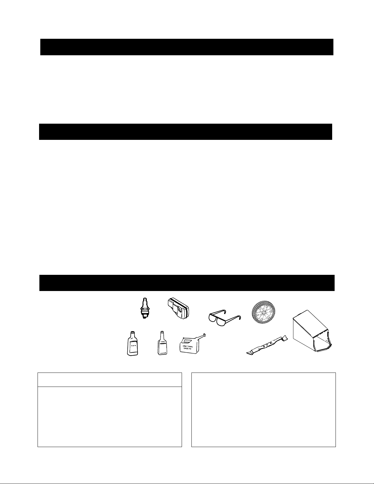
TABLE OF CONTENTS
Content Page
Warranty Information ................................... 2
Safe Operation Practices.............................3
Slope Gauge...................... ........... ......... ......6
Assembly ..................................................... 7
Operation..................................................... 9
Maintenance..................................................12
Content Page
Service & Adjustment..................................... 15
Storage..........................................................17
Trouble-Shooting...........................................19
Parts List........................................................20
Espanól.......................................................... 26
WARRANTY INFORMATION
Two-Year Warranty on Craftsman Lawn Mower
For two years from the date of purchase, when this Craftsman lawn mower is maintained, lubricated , and tuned
up according to the instructions in the owner’s manual, Sears will repair, free of charge, any defect s in material or
workmanship. If this lawn mower is used for commercial or rental purposes, this warranty applies for only 90 days
from the date of purchase.
This warranty does not cover:
1. Expendable items which become worn during normal use, such as rotary mower blades, blade adapters,
belts, air cleaners and spark plug.
2. Repairs necessary because of operator abuse or negligence, including bent crankshafts and the failure t o
maintain equipment according to the instructions contained in the owner’s manual.
WARRANTY SERVICE IS AVAILABLE BY RETURNING THE CRAFTSMAN LAWN MOWER TO THE
NEAREST SEARS SERVICE CENTER IN THE UNITED STATES. THIS WARRANTY APPLIES ONLY WHILE
THIS PRODUCT IS IN USE IN THE UNITED STATES.
This warranty gives you specific legal rights, and you may also have other rights which vary from state t o state.
Sears, Roebuck And Co., D/817WA, Hoffman Estates, IL 60179
ACCESSORIES
These accessorie s were
available when the lawn
mower was purchased. They
are also availab le at most
Sears retail outl ets, an d
service centers. Most Sears
stores can order repair parts
for you when you pr ovide the
model number of your l awn
mower.
PRODUCT SPECIFICATIONS
Horsepower: 4.0
Engine Oil 21 oz. SAE 30 oil
Fuel Capacity: 1.5 quarts
Spark Plug J19LM
Spark Plug
Engine Oil
Stabilizer
Gap .030 inches
Muffler
Gas Can
Safety
Glasses
Please record model number, serial number, and
date of purchase here for future reference. You will
find this information on the model plate located on
the cutting deck of your mower.
Model Number .........................................................
Serial Number...........................................................
Date of Purchase ......................................................
Wheels
Blade
Grass Catcher
2
Page 3

SAFE OPERATION PRACTICES
This symbol points out important safety instructions which, if not followed, could endanger the per-
sonal safety and/or property of yourself and others. Read and follow all instructions in this manual before
attempting to operate your lawn mower. Failure to comply with these instructions may result in personal
injury. When you see this symbol—heed its warning.
Your lawn mower was built to be operated according to the rules for safe operation in this
DANGER:
This unit is equi pped with a n internal combusti on engine a nd shoul d not be used o n or near an y unimpr oved
forest-cove red, bru sh-cov ered or gr ass-co vered l and unle ss the eng ine’s exha ust syst em is equi pped wit h a
spark arreste r meetin g applica ble lo cal or sta te law s (if any) . If a sp ark arre ster i s used, it should be
maintained in ef fective w orking ord er by the operator .
In the State of Ca liforni a the ab ove is requ ired by la w (Sectio n 4442 of t he Calif ornia Publ ic Reso urces
Code). Other stat es may have s imilar laws. Federa l laws ap ply on fede ral lands . A spark arrester f or the
muffler is available through your nearest Sears Authorized Service Center (See the REPAIR PARTS section
of this manual. )
WARNING: The engine exhaust fr om this pro duct con tains ch emicals known to the State of C alifor nia to
cause cancer, bi rth defect s or oth er reprod uctive ha rm.
manual. As with any type of power equipment, carelessness or error on the part of the operator
can result in se rious injury. If you violate any of these rules, you ma y ca use seri ous injury t o
yourself or others.
S
A
F
E
T
Y
GENERAL OPERATION
• Read this owner’s guide carefully in its entirety
before attemptin g to asse mble this machine .
Read, understan d, and fo llow all instru ctions o n
the machine and in t he manual(s ) before
operation. Be completely familiar with the controls
and the proper use o f this machi ne befor e
operating it. K eep this ma nual in a sa fe plac e for
future and regul ar refer ence, and fo r orderi ng
replacement par ts.
• Your rotary mower is a precisi on piece of power
equipment, not a playthi ng. There fore, exer cise
extreme caution at all ti mes. Your un it has bee n
designed to perform on e job: to mow gras s. Do not
use it for any othe r purpose.
• Never allow chi ldren u nder 14 yea rs ol d to operat e
a power mower. Child ren 14 year s old and ov er
should only opera te mower u nder close parental
supervision. O nly resp onsibl e indivi duals wh o are
familiar with these rules of safe operation should
be allowed to use your mower.
• Keep the area of operation clear of all persons,
particularly small ch ildren an d pets. St op engin e
when they are in the vicini ty of your mower to h elp
prevent blade cont act or thr own obje ct injury .
Although the area of operat ion shoul d be
completely cl eared of f oreign obj ects, an object
may have been overlo oked and coul d be
accidentally thrown by the mower in any direction
and cause serio us personal injury to the ope rator
or any others al lowed in t he area.
• Thoroughly inspect the area w here the e quipment
is to be used. Remove all stones, sticks, wire,
bones, toys and ot her forei gn obje cts which could
be picked up and thr own by th e mower in any
direction and ca use serio us perso nal inju ry to th e
operator or any ot hers allow ed in the ar ea. Plan
your mowing patt ern to avoid di scharge o f materi al
toward roads, side walks, b ystanders and the li ke.
To help avoid a thrown object’s injury, keep
children, byst anders and helpers at least 75 feet
from the mower while it is in operation.
• Always wear safe ty glas ses or sa fety go ggles
during operati on or while performing a n adjustment
or repair, to pr otect eye s from fo reign ob jects th at
may be thrown from the machine i n any direc tion.
• Wear sturdy, rough -soled wo rk shoes and close fitting slac ks and shirt s. Shirts and pants that cover
the arms and legs and steel-t oed shoes are
recommended. Do no t wear loos e fitti ng clo thes or
jewelry. They ca n be caught in moving pa rts. Never
operate a unit in bar e feet, sandals , slippery or li ght
weight (e.g. canvas) shoes.
• Do not put hands or fee t near or under rotat ing
parts. Keep cle ar of disc harge open ing at all times
as the rotatin g blade can cause inj ury.
• Many injuries occu r as a res ult of the mower being
pulled over the f oot during a fall. D o not hang on to
the mower if you are falling; release t he handl e
immediately.
• Never pull the mower toward you while you are
walking. If you mu st back the mower away from a
3
Page 4

wall or obstr uction fir st look down and behind, and
then follow these s teps:
a. Step back from the mower to fully extend your
arms.
b. Be sure you are wel l balanc ed with su re
footing.
c. Pull the mower back slowly, n o more than half
way toward yo u.
d. Repeat these step s as neede d.
• Do not operate the mo wer while un der the
influence of a lcohol o r drugs.
• Do not engage the se lf-pro pelled mec hanism on
units so equipped while st arting en gine.
• The blade control handle is a safety devi ce. Never
attempt to bypas s its ope ration . Doing so makes
the safety devic e inope rative and may result in
personal injury through contac t with th e rotatin g
blade. The blade con trol handl e must oper ate
easily in both dir ections and automati cally re turn
to the disengaged po siti on when rel eased.
• Never operate t he mower in w et grass. Al ways be
sure of your footing. A slip and fall can cause
serious person al injur y. Keep a f irm hold on the
handle and walk, n ever run. I f you feel you are
losing your foot ing, RELEASE THE BLADE
CONTROL HANDLE IMMEDIATLE Y and the
blade will stop rotating within three seconds.
• Mow only in dayli ght or good ar tific ial li ght.
• Stop the blade when crossing gravel dri ves, walks
or roads.
• If the equipme nt should s tart to vibrate
abnormally, sto p the engine and chec k
immediately fo r the cause. Vibration is generally a
warning of troubl e.
• Shut the engine of f and wait until t he blade comes
to a complete stop b efore remo ving t he grass
catcher or unclog ging the chute. The cutti ng
blade continues to rotate for a few seconds after
the engine is shut off. Nev er place any part of the
body in the blade ar ea until you are sure the blade
has stopped rota ting.
• Never operate mowe r without pr oper guard s,
grass catcher, pl ates or other safe ty prot ective
devices in pl ace.
• Muffler and eng ine become h ot and can cau se a
burn. Do not touch.
• Do not adjust the throttle control with the engine
running.
• Only use access ories app roved fo r this machine
by the manufactu rer. Rea d, underst and, and
follow all instructions provided with the approved
accessory.
• If situations occur which are not covered in this
manual, use care and g ood judg ment. Cont act
your dealer for assistance.
Slope Operation
For your safety, use the slope gauge included as part of
this manual to measure slopes before operating this unit on
a slope or hilly area. If the slope is greater than 15 degrees
as shown on the slope gauge (page 6), do not operate this
unit on that area or serious injury could result.
DO:
• Mow across the face of slopes ; never u p and
down. Exercise ex treme ca ution when changi ng
direction on slop es.
• Watch for holes, ruts, hi dden object s, or bu mps.
Tall grass can hide obstacle s.
• Always be sure of yo ur footi ng. A sl ip and fal l can
cause serious per sonal in jury. If you feel you are
losing your balanc e relea se the blad e contro l
handle immediately and the blade will stop in less
than 3 seconds.
• ON MODELS WITH CASTER WHEELS: Lock
both front wheel s so they do not pi vot whil e
mowing on the face of slopes. To turn t he mower,
depress the handle and raise t he front wheels
slightly.
DO NOT:
• Do not mow near drop-of fs, dit ches or
embankments. The oper ator cou ld lose foot ing or
balance.
• Do not mow slopes gr eater th an 15 degre es as
shown on the slope g auge.
• Do not mow on wet grass. Reduced foo ting coul d
cause slipping.
• ON MOWERS WITH CASTER WHEELS: Do Not
mow on slopes with c asters unlo cked sinc e the
mower has a tendency to drift down hill.
Children
Tragic accidents can occur if the operator is not alert to the
presence of children. Children are often attracted to the
mower and the mowing activity. Never assume that
children will remain where you last saw them.
• Keep children out of the mowing area and und er
the watchful care of a responsible adult ot her than
the operator.
• Be alert and turn mow er off if a child en ters th e
area.
• Before and while mov ing back wards, l ook behind
and down for small children or other objects.
• Never allow childr en under ag e 14 to oper ate the
mower. Children 14 years of ag e and abov e
should read and under stand t he operat ion
instructions and safety rules in this manual.
• Use extreme care when ap proachi ng blind
corners, shrub s, tree s, or ot her object s that ma y
obscure your vis ion of a child or h azard.
Service
• Use extreme care in han dling gas oline and other
fuels. They are ex tremely f lammabl e and the
vapors are explosi ve.
• Use only an approve d gasolin e contain er.
• Never remove gas cap or add fuel while t he
engine is runnin g. Allow e ngine to cool at l east
two minutes befor e refueli ng.
4
Page 5
• Replace gasoline cap secure ly and wi pe off any
spilled gasoline before starting the engine as it
may cause a fire or explos ion.
• Extinguish all c igaret tes, cigar s, pip es and other
sources of ignit ion.
• Never refuel machine indoors because flammabl e
vapors will accumulate in the area.
• Never store the mac hine or fue l cont ainer ins ide
where there is an open fla me or sp ark such as a
gas water heater, space he ater, or furnace.
• Never run an engine inside a c losed area .
• To reduce fire ha zard, k eep mower fre e of gras s,
leaves, or othe r debris bui ld-up. Clean up oi l or
fuel spillage. Allow mower to cool at least 5
minutes before s toring.
• Before cleaning, repair ing, or in spectin g, make
certain the bl ade and all moving pa rts have
stopped. Disconn ect the spark plug wire, and
keep the wire away fr om the spark plug to prevent
accidental st arting.
• Check the blade an d engine moun ting bolt s at
frequent int ervals f or proper tightn ess. Al so,
visually ins pect blad e for damag e (e.g., bent,
cracked or worn). Replace with bl ade which
meets original equipme nt specif icati ons liste d in
this manual.
• Keep all nuts, bolts, an d screws t ight to be sure
the equipment is in safe working condition.
• Never tamper with safety devices. Check their
proper operation regularly.
• After striking a foreig n object, stop th e engine,
remove the wire fr om the spar k plug, an d
thoroughly insp ect the mower for any damage.
Repair the damage bef ore sta rting and o perati ng
the mower.
• Never attempt to make a wheel or cutting height
adjustment while the engi ne is runni ng.
• Grass catcher comp onents ar e subje ct to wear ,
damage and deteriora tion, which coul d expose
moving parts or al low object s to be thro wn. For
safety protec tion, fr equen tly chec k compone nts
and replace with manufactur er’s reco mmended
parts, when necessary.
• Mower blades are shar p and can c ut. Wrap t he
blade(s) or wear gloves, and use extr a caution
when servicing th em.
• Do not change the en gine gover nor sett ing or
overspeed the eng ine. Exc essive engine spee ds
are dangerous.
YOUR RESPONSIBILITY
Restrict the use of this power machine to
persons who read , understand and follow the
warnings and instructions in this manual and
on the machine.
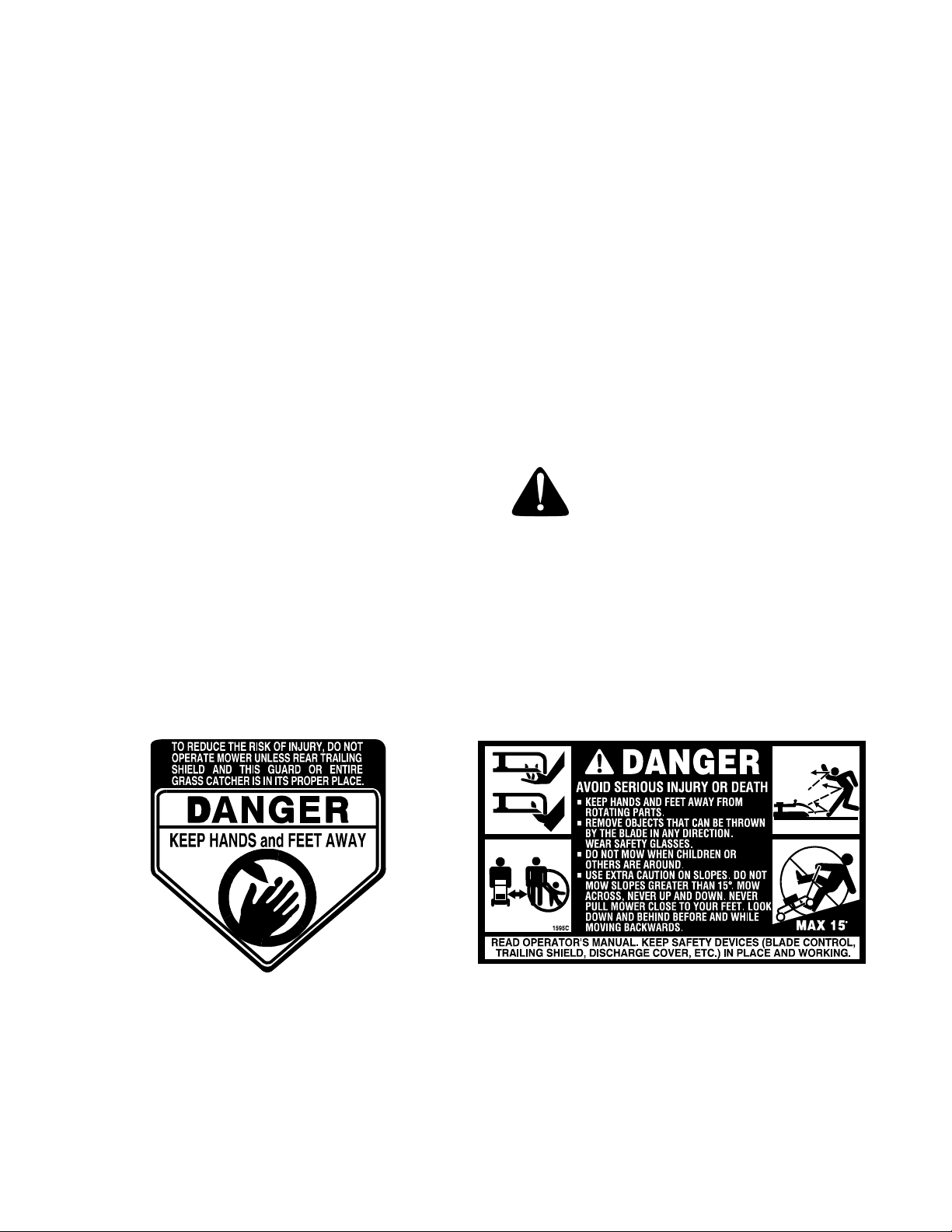
Following are representations of the safety labels on your lawn mower. Maintain safety wh ile operating the mower.
Please have the part number ready when re-ordering safety labels.
SAVE THESE INSTRUCTIONS FOR FUTURE REFERENCE.
5
Page 6
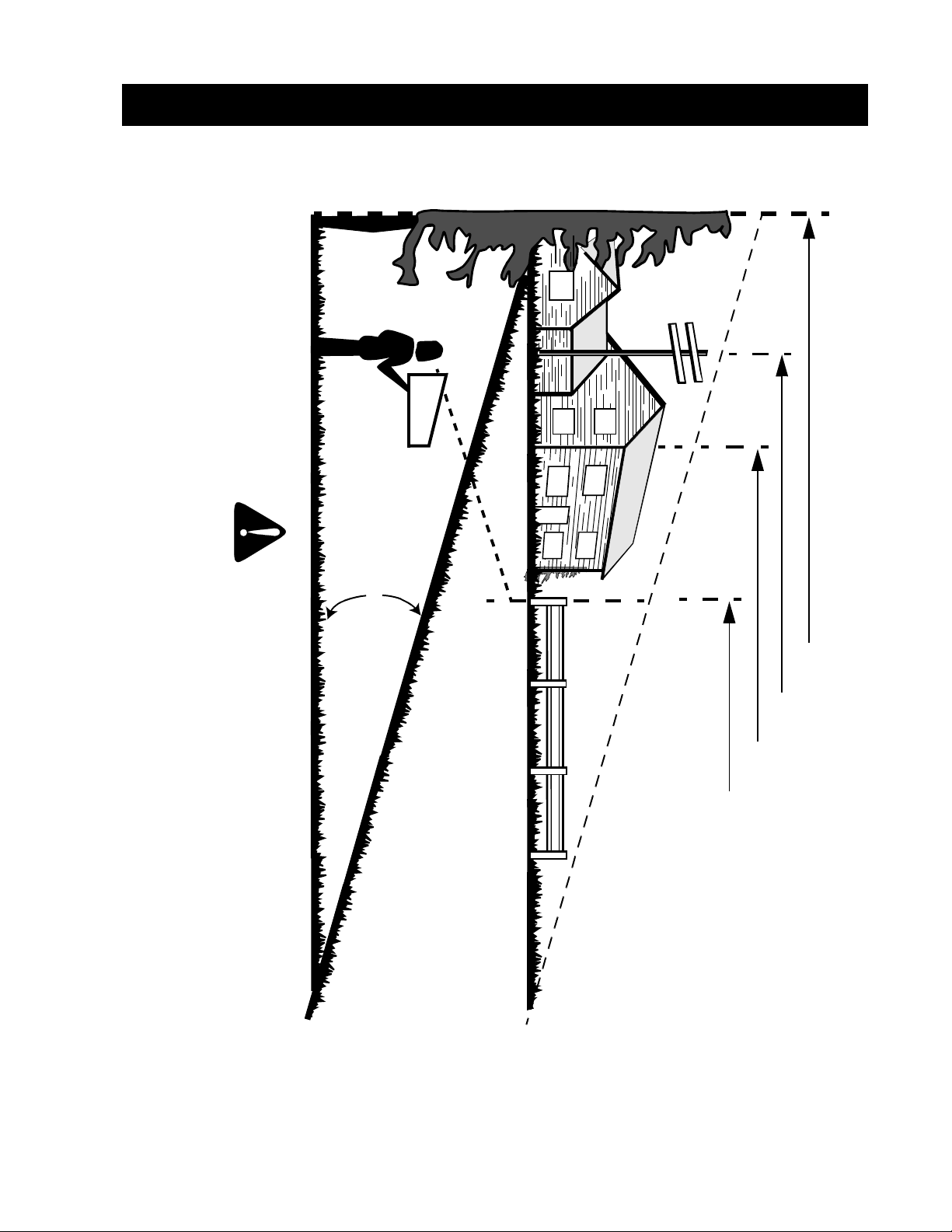
SLOPE GUAGE
USE THIS PAGE AS A GUIDE TO DETERMINE SLOPES WHERE YOU MAY NOT
OPERATE SAFELY:
Operate R
Operate WALK-BEHIND
IDING mowers up and down slopes, never across the face of slopes.
mowers across the face of slopes, never up and down slopes.
is extremely difficult to maintain your footing and you could slip, resulting in serious in
jury.
Do not mow on i nclines with a s lope in e xcess of 15 deg
A riding mower could ov erturn and cause serious injury. If operating a
rees (a rise of approximately 2-1/2 feet e very 10 feet).
walk-behind mow er on such a slope, it
WARNING
F
O
L
D
O
N
D
O
T
N
T
E
D
L
I
N
E
,
R
E
P
R
E
S
E
A CORNER OF A BUILDING
SIGHT AND HOLD THIS LEVEL WITH A VERTICAL TREE
A POWER POLE
15°
T
I
N
G
A
1
5
°
S
L
O
P
E
OR A FENCE POST
6
Page 7
ASSEMBLY
Removing Unit From Carton
• Remove staples, break glue on top flaps, or cut
tape at carton end and peel along top flap to
open carton.
• Remove loose parts if included with unit (i.e.,
owner's manual, etc.).
• Cut along dotted lines and lay carton down flat.
• Remove packing material. Roll unit out of
carton. Check carton thoroughly for loose parts.
Note: Make sure not to crimp the cable while
removing loose parts or the unit from the carton.
IMPORTANT: This unit is shipped without gasoline
or oil in the engine. Be certain to service engine with
gasoline and oil before operating your mower.
NOTE: Reference to right or left hand side of the
mower and/or front or behind the mower is observed
from the operating position.
Loose Parts
a. Owner’s Manual
b. A Bottle of Engine Oil
c. Parts for Grass Bag: Frame, Bag
d. Discharge Chute
Tools Required
a. Pair of Pliers
b. Funnel
Disconnecting Spark Plug
• Before setting up your lawn mower, disconnect
the spark plug wire from the spark plug, and
ground it against the engine. See Figure 1.
• Attach rubber boot to a bolt on the engine to
ground as shown below.
Spark Plug
Wire
Rubber Boot
Spark Plug
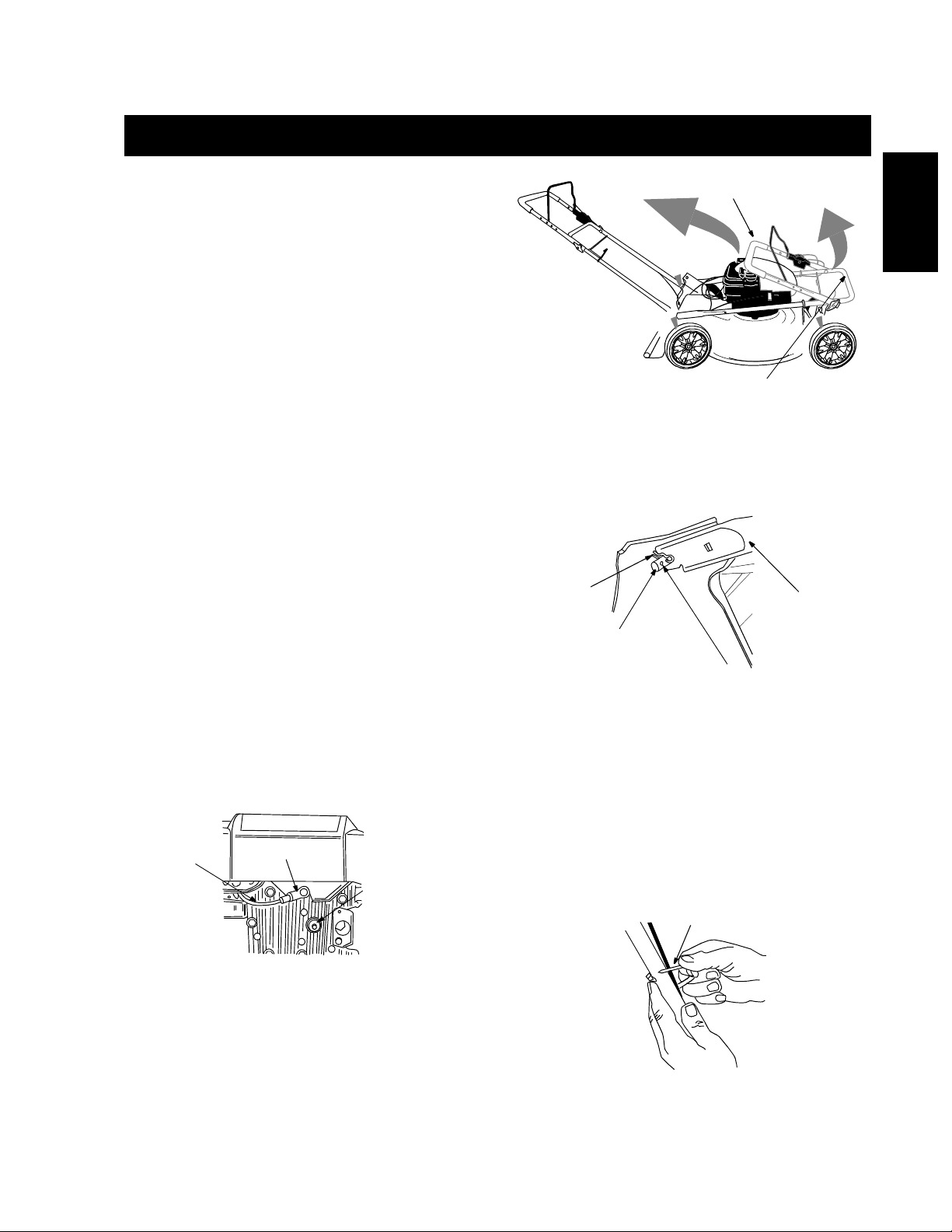
B
For shipping purposes, the hairpin clip is placed in the
outer hole of the weld pin on the lower handle.
• Remove the hairpin clip from the outer hole of
the weld pin. See Figure 3.
Hairpin
Clip
Weld Pin
• Using a pair of pliers, insert the hairpin clip into
the inner hole in the weld pin. See Figure 3.
Repeat on other side.
• Raise the upper handle in the direction B shown
in Figure 2. Tighten the wing nuts which are
already on the handle.
• Attach control cable to the lower handle with the
cable tie already on the lower handle. Pull tight
the cable tie and cut off extra. See Figure 4.
Upper Handle
A
Lower Handle
Figure 2
Lower
Handle
Outer Hole on
Weld Pin
Figure 3
Cable Tie
A
S
S
E
M
B
L
Y
Figure 1
Assembling Handle
• Raise lower handle in direction A shown in
Figure 2. It should snap into place.
Note: Make sure to route the cable inside the lower
handle. Also do not crimp the cable while lifting the
handle up
Figure 4
7
Page 8
Attaching Starter Rope
The rope guide is already attached to the right si de of
the upper handle of your mower. See Figure 5.
• With the spark plug wire disconnected and
grounded, hold the blade control handle against the
upper handle, and pull starter rope out of the engine.
• Slip the rope through the rope guide as shown in
Figure 5. Tighten the wing nut holding the rope
guide to the upper handle.
Recoil
Starter
Rope
Guide
Wing Nut
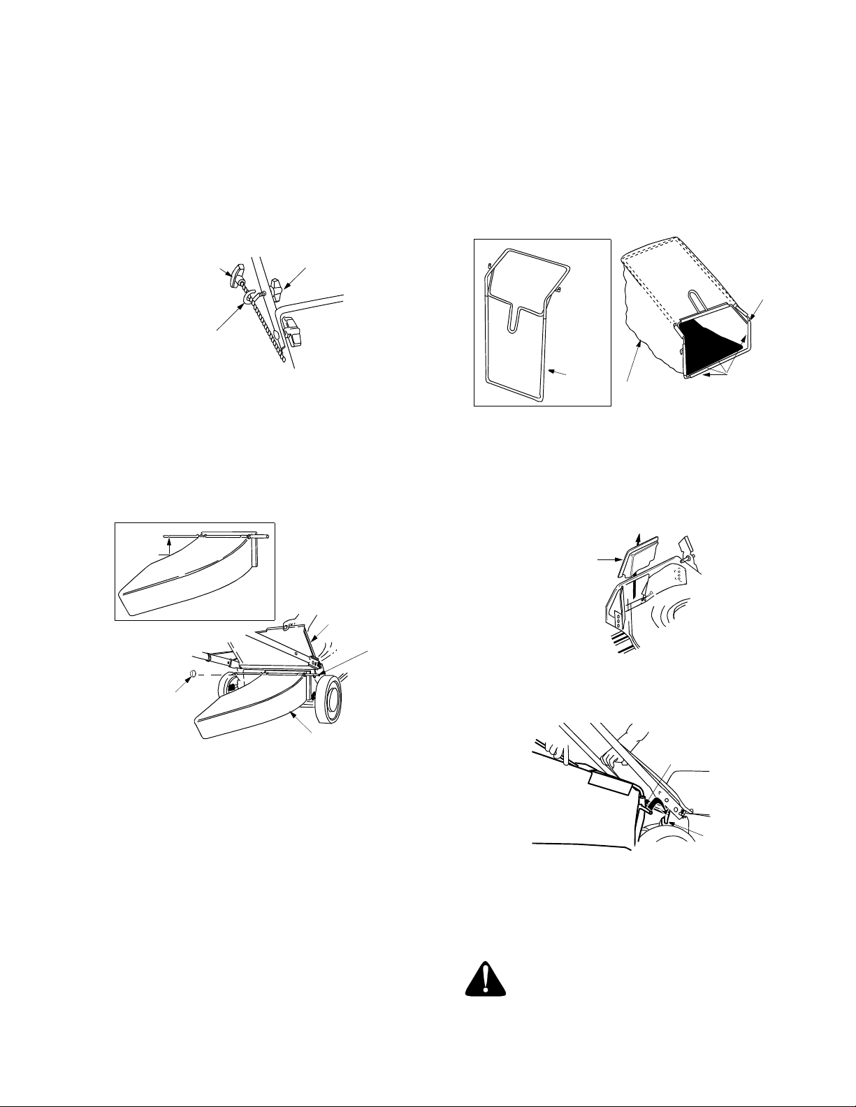
• Place bag over frame (black plastic side is the
bottom of bag). Slip the openings in the side of
the plastic channel on bag over the hooks on the
grass catcher frame.
• Secure bag to frame by working the plastic
channels on bag over frame as shown in Figure
7. All of the plastic channels except center top of
bag attach from the outside of bag. Center top of
bag attaches from the inside of bag.
Hook
Figure 5
Attaching Discharge Chute
• There is a groove 2” from the left end of the r od.
Bend and snap off approximately 2” of the rod
with a pair of vise grips. See Figure 6.
• Insert push cap, provided with the chute ro d,
onto the end of the rod which you just snapped
off. Tap on with a hammer. See Figure 6.
Groove
Rear Discharge
Door
Chute
Rod
Push
Cap
Discharge
Chute
Figure 6
• To attach discharge chute: Lift the discharge
door and place the ends of the chute rod into
the slot on each handle bracket assembly.
Release the rear discharge door.
• To remove discharge chute: Lift the rear
discharge door of the mower. Lift the discharge
chute up and outwards and pull it out of the
slots on the handle b racket assemblies.
Release the rear discharge door.
Assembling Grass Catcher
NOTE: Make certain bag is turned right side out
before assembling (warning label will be on the
outside).
Frame
Grass
Bag
Channels
Figure 7
Attaching Grass Catcher to Mower
• Lift the chute door on the mower. Remove the
mulching plug or the discharge chute. See
Figure 8.
Mulching
Plug
Figure 8
• Holding the grass bag firmly, place the bag on
the mower as shown in Figure 9.
Hook
Grass Catcher
Slot
Figure 9
• Place hooks, located on two sides of the grass
catcher frame, in the slots on the handle
brackets. See Figure 9. Release the chute
door.
Warning: Never operate the mower unless
the grass catcher frame is firmly seated on
the chute door pivot rod, and the rear
discharge door rests firmly on top of the
grass catcher.
8
Plastic
Page 9

OPERATION
Know Your Lawn Mower
Read this owner’s manual and safety rules before operating your lawn mower. Compare the illustrati ons in Figure
10 with your lawn mower to familiarize yourself with the location of various controls and adjustments. Save this
manual for future reference.
WARNING: The operation of any lawn mower can result in foreign objects being thrown into th e
operator’s eyes and causing severe eye damage. Always wear safety glasses while operating the
mower, or while performing any adjustments or repairs on it.
Blade Control
Handle
Front Height
Adjustment Lever
Recoil Starter
Oil Fill Plug
Grass Catcher
Gas Tank Cap
Rear Height Adjustment Lever
O
P
E
R
A
T
I
O
N
Spark Plug Wire
Primer
Figure 10
Recoil Starter
The recoil starter is attached to the handle. Stand
behind the unit and pull the recoil starter to start
the unit.
Primer
The primer is used to pump gas into the carburetor.
Use it to start a cold engine, but do not use it to
restart a warm engine after short shutdown.
Blade Control Handle
The blade control handle is located on the upper
handle of the mower. The blade control handle must
be depressed in order to operate the unit. Release
blade control handle to stop engine and blade.
Height Adjustment Lever
These levers are located on each wheel and are used
to adjust the cutting height. All four levers have to be at
the same relative position to ensure uniform cut.
WARNING: This blade control mechanism
is a safety device. Never attempt to bypass
its operations.
Meets CPSC Blade Safety Standards
Craftsman Walk-Behind Lawn Mowers conform to the safety standards of the American National Standards Institute
and the U.S. Consumer Product Safety Commission.
9
Page 10

Stopping Engine
• Release blade control handle to stop the
engine and the blade.
• Disconnect spark plug wire and move away
from spark plug to prevent accidental starting.
WARNING: Before using your lawn mower,
again refer to the safety rules on pages 3-5
of this manual. Always be careful.
Gas And Oil Fill-Up
Engine Oil
Only use high quality detergent oil rated with API
service classification SF, SG or SH. Select the oil’s
viscosity grade according to your expected operating
temperature. Follow the chart below.
32oF
WarmerColder
Starting Engine
(Refer to Figure 11.)
WARNING: Be sure no one other than the
operator is standing near the lawn mower
while starting or operating.
• Attach spark plug wire to spark plug. Make
certain the metal cap on the end of the spark
plug wire is fastened securely over the metal tip
on the spark plug.
WARNING: Never run engine indoors or in
enclosed, poorly ventilated areas. Engine
exhaust contains carbon monoxide, an
odorless and deadly gas.
WARNING: Keep hands, feet, hair and
loose clothing away from any moving parts
on engine and lawn mower.
5W30 SAE 30
Oil Viscosity Grade Chart
• Use SAE30 oil; do not use 10W40 oil.
• Fill oil sump and check the oil level as follows:
a. Position the mower on level ground.
b. Clean area around oil fill plug.
c. Remove oil fill plug and dipstick.
d. Wipe dipstick clean, insert it into oil fill hole
and tighten securely.
e. Remove dipstick and check oil level. If t he
oil is not upto FULL mark on the dipstick,
pour recommended oil through the oil fill
and check the level again.
• Install oil fill plug and dipstick, tighten securely.
NOTE: Although multi-viscosity oils (5W30, 10W30,
etc.) improve starting in cold weather, these
multiviscosity oils will result in increased oil
o
consumption when used above 32
F. Check the oil
level more frequently to avoid possible engine
damage from running low on oil.
Gasoline
WARNING: Never fill fuel tank indoors, or
when engine is running or hot. Do not
smoke when filling fuel tank.
• Push primer three times. Wait about two
seconds between each push. In cold weather
o
around 55
F or below, prime five times. Do not
prime to restart a warm engine after a short
shutdown.
• Hold control handle against the upper handle.
Grasp recoil starter and pull rope out slowly
until engine reaches the start of compression
cycle (rope will pull slightly harder at this point).
See Figure 11 inset. Let the rope rewind slowly.
Hold handles firmly
Check/fill oil
Pull recoil starter
Fill gasoline
• Clean area around gas tank cap. For location,
see Figure 10. Remove cap.
• Use a funnel to prevent spillage.
• Pour approximately 1.5 quarts of fresh, regul ar
grade, unleaded gasoline slowly to the fuel tank.
IMPORTANT: Never mix engine oil with gasoline.
• Fill tank to 1/2” below the bottom of the filler
neck. Wipe any fuel spillage. Do not fill fuel tank
completely. Provide space for fuel expansion.
Attach spark
plug wire
10
Prime 3 times
Figure 11
Page 11

• Pull rope with a rapid, continuous, full arm
stroke. Keeping a firm grip on the recoil starter,
let the rope return to the starter slowly.
Using Your Lawn Mower
Your mower is designed to operate as a mulching or a
side discharge unit.
• For converting from a mulcher to a side
discharge unit, refer to instructions on page 8.
Do not operate mower without the mulching
deflector or the grass catcher properly
installed and tightly secured.
• Be sure that lawn is clear of stones, sticks,
wire, or other objects which could damage lawn
mower or engine. Such objects could be
accidently thrown by the mower in any direction
and cause serious personal injury to the
operator and others.
• For best results, do not cut wet grass because
it tends to stick to the underside of the mower,
preventing proper discharge of grass clippings,
and could cause you to slip and fall. New grass,
thick grass or wet grass may require a
narrower cut. Blade speed should be adjusted
to the condition of the lawn.
• The best mowing pattern is one that allows the
clippings to discharge towards the uncut part of
the lawn. This permits recutting of the clippings
to further pulverize them. When cutting high
weeds, discharge towards cut portion, then
recut at right angles to first direction.
• For a healthy lawn, always cut off one-third or
less of the total length of the grass. Lawn should
be cut in the fall as long as there is growth.
• This mower is designed to be operated at full
throttle to give you the best cut an d do the
most effective job of bagging the clippings.
• Operate the mower till the grass catcher bag is
full, or the job has been completed whichever is
earlier.
• Stop the engine completely by releasing the
blade control handle. Make sure that the unit
has come to a complete stop and the blade has
stopped rotating. Empty the grass catcher bag
as follows.
• Lift the discharge door and pull the grass bag
away from the mower as shown in Figure 12.
• Holding the bag firmly, carry the bag away from
the mower. Dispose off the clippings
appropriately.
Chute Door
Bag Handle
Hold bag with
clippings firmly
WARNING: If the mower strikes a foreign
object, stop the engine. Remove spark plug
wire from spark plug and thoroughly inspect
the mower for any damage. Repair the
damage before restarting the mower.
Extensive vibration during operation is an
indication of equipment damage.
Using Grass Catcher
You can use the grass catcher bag to collec t clippings
while operating the mower.
• Attach the grass catcher to the mower fo llowing
instructions on page 8 of this manual.
Figure 12
Height Adjustment
Refer to height adjustments section of this manual on
page 16 for instruction on how to adjust the cutting
height and the handle height.
For best results in mowing, keep the cutting height
position high until it is determined which height is best
for your lawn.
11
Page 12

MAINTENANCE
General Recommendations
• Always observe safety rules when performing
any maintenance.
• The warranty on this lawn mower does not cover
items that have been subjected to operator abuse
or negligence. To receive full value from the
warranty, oper ator must maintain th e lawn mower
as instructed in this manual.
• Changing of engine governed speed will void
engine warranty.
• Some adjustments will have to be made
periodically to maintain your unit properly.
• All adjustments in the Service and Adjustments
section of this manual should be checked at
least once each season.
• Follow the maintenance schedule given below.
• Periodically check all fasteners and make sure
these are tight.
WARNING: Always stop the engine and
disconnect the spark plug wire befor e
performing any maintenance or adjustments.
Cleaning
The underside of the mower deck should be cleaned
after each use to prevent any buildup of grass clippings,
leaves, dirt , or other debris. If this debris is allowed to
accumulate, it wi ll result in rust and corrosion.
• Disconnect spark plug wire.
• Drain the gasoline from the lawn mower, or
place a piece of plastic under the gas cap.
• Tip the mower so that it rests on the housing.
Keep the side with the air cleaner facing up.
Hold it firmly.
• Scrape clean the underside of the deck with a
suitable tool.
• Put the mower back on its wheels on the
ground. If you had put plastic under the gas
cap, make sure to remove it now.
WARNING: Never tip the mower more
than 90 degrees and do not leave the
mower tipped for any length of time. Oil
can drain into the upper part of the engine
causing a starting problem.
NOTE: We do not recommend using a garden hose to
clean mower unless the muffler, air filter and
carburetor are covered to keep water out. Water in
engine can shorten engine life.
Engine Maintenance
WARNING: Always stop engine,
disconnect spark plug wire, and move it
away from spark plug before performing any
adjustments or repairs.
Customer Responsibilities
MAINTENANCE
SCHEDULE
Lubricate wheels
T
C
Lubricate casters
U
D
O
Lubricate blade control
R
P
Clean deck
Blade care
Change oil
Replace air filter
E
N
I
G
Clean engine
N
E
Check spark plug
Check spark arrester (if any)
r
e
t
f
A
s
s
e
s
u
h
c
a
e
F
s
r
u
o
o
h
h
5
o
2
w
y
t
r
t
e
s
v
ir
E
E
s
r
u
o
h
0
5
y
r
e
v
E
r
r
u
u
o
h
0
0
1
y
r
e
v
O
n
e
o
g
s
a
r
a
o
e
t
s
s
a
e
r
e
o
f
c
e
n
B
SERVICE
DATES
12
Page 13

Engine Oil
• Only use high quality detergent oil rated with
API service classification SF, SG or SH. Se lect
the oil’s viscosity grade according to your
expected operating temperature. Refer to page
10 of this manual for viscosity chart.
• Stop engine and wait several minutes before
checking oil level. With engine on level ground,
the oil must be to FULL mark on dipstick .
• Change engine oil after the first five hours of
operation, and every twenty-five hours
thereafter.
To Change Engine Oil
Change oil after first two operating hours and every
25 operating hours thereafter. Drain oil while engine
is warm. Follow the instructions given below.
• Tip the mower with the spark plug facing up.
• Place a container under the dipstick. Pull the
dipstick out of oil fill.
• Drain the oil sump empty, collecting oil in an
approved container.
• Fill oil sump with 21 ounces of fresh SAE 30 oil.
Refer to page 10 of this manual for oil fill-up
instructions.
Air Cleaner
The air cleaner prevents damaging dirt, dust, etc.,
from entering the carburetor and being forced into the
engine and is important to engine life and
performance. Replace filter once a year or every 100
operating hours, more often if used in extremely dusty
conditions.
To Service Air Cleaner:
• Turn air filter cover counterclockwise and
remove the cover and filter from the flange.
See Figure 13. Discard filter.
o
n
t
e
t
n
h
r
g
u
i
T
t
e
o
v
t
o
n
r
m
u
e
r
T
• Clean cover and flange thoroughly.
• Insert the new filter into the cover.
• Place the cover and the filter agains t flange
with tab on the cover inserted into lower left
corner of slot in flange. See Figure 13.
• Push cover firmly against flange and turn it
clockwise as far as it will go. Make sure that the
retainers are locked around the flange. See
Figure 13.
WARNING: Never run the engine without
air cleaner completely assembled.
Clean Engine
• Clean engine periodically. Remove dirt and
debris with a cloth or brush.
• Frequently remove grass clippings, dirt and
debris from cooling fins, air intake screen and
levers and linkage. This will help ensure
adequate cooling and correct engine speed.
NOTE: Do not clean with a forceful spray of wate r as
water could contaminate the fuel system.
Spark Plug
• Clean spark plug and reset gap to .030" at least
once a season or every 50 hours of operation.
See Figure 14. Spark plug replacement is
recommended at the start of each season. Refer
to engine parts list for correct spark plug type.
NOTE: Do not sandblast spark plug. Spark plug
should be cleaned by scraping or wire brushing and
washing with a commercial solvent.
Feeler gap .030”
Spark Plug
M
A
I
N
T
E
N
A
N
C
E
Flange
Slot
Tab
Retainer
Figure 13
Air Cleaner
Filter
Retainer
Cover
13
Muffler
Figure 14
WARNING: Do not operate the lawn
mower without a muffler, or tamper with
the exhaust system. Damaged mufflers or
spark arresters could create a fire hazard.
Temperature of muffler and nearby areas
may exceed 150
o
F(65
o
C).
Page 14

Blade Care
Lubrication
Periodically inspect the blade adapter for crac ks,
especially if you strike a foreign object. Replace when
necessary.
WARNING: When inspecting the cutting
blade, protect hands by using heavy
gloves or a rag to grasp the cutting
blade.
• Disconnect spark plug wire from spark plug.
• Turn mower on its side making sure that the air
filter and the carburetor are up to check the
blade. If the blade needs to be serviced, refer
to the instructions on blade care in the “Service
& Adjustments” section of this manual.
Wheels
• Lubricate the wheels at least once a season
with light oil or engine oil. Also, if the wheels are
removed for any reason, lubricate the surface
of the axle bolt and the inner surface of the
wheel with light oil.
Blade Control Handle
• Lubricate the pivot points on the blade control
handle and the brake cable at least once a
season with light oil. The blade control handle
must operate freely in both directions. For
complete lubrication chart, see Figure 15.
Chute Deflector
• Lubricate t he torsion spring and the pivot point
on each end of the chute deflector using a light
oil. This will prevent rusting and ensure that the
deflector, which is a safety device, can always
work properly.
Figure 15
Lubricate
Lubricate
NOTE: For sake of clarity, illustrations in the insets represent view from another perspective rather than from the operating position.
Figure 15: Lubrication Chart
Lubricate
14
Page 15

SERVICE & ADJUSTMENTS
Servicing Blade
To Remove Blade
• Remove the bolt and blade bell support which
hold the blade and adapter to the engine
crankshaft. See Figure 16.
• Remove the blade and adapter from the
crankshaft.
To Replace Blade:
• Before reinstalling the blade and the blade
adapter to the unit, lubricate the engine
crankshaft and the inner surface of the blade
adapter with light oil.
• Install the blade adapter on the crankshaf t with
the “star” away from the engine. See Figure 16.
Blade Adapter
Hex Bolt
• Place the new blade with the side marked
bottom (or with part number) facing away from
the adapter.
• Place the bell support next. Make sure to align
the tabs in the holes of the blade with the hole in
the bell support.
• Insert the hex bolt through the blade as sembly.
Figure 16 shows the correct order of assembly.
• Use block of wood to hold blade again while you
tighten the bolt clockwise. Follow the
recommended torque for the bolt which is 450600 in.-lbs.
IMPORTANT: The bolt, used to secure the blade to
the engine, is specially heat-treated. Do not
substitute. To order replacement bolt, refer to the
Repair Parts section of this manual.
WARNING: To ensure safe operation of
your unit, all nuts and bolts must be
checked periodically for correct tightness.
Crankshaft
Blade
Blade Bell
Support
Figure 16
To Sharpen Blade:
The blade can be sharpened with a file or on a grinding
wheel. Do not attempt to sharpen while on the mower.
• Follow the original angle of grind as a guide.
Make sure that each cutting edge receives an
equal amount of grinding to prevent an
unbalanced blade.
NOTE: An unbalanced blade will cause excessive
vibration when rotating at high speeds, may cause
damage to the mower and could break, causing
personal injury.
• Test the blade by balancing it on a round shaft
screwdriver or a blade balancer. See Figure 17.
• If the blade is not balanced, remove metal from
the heavy side until it balances evenly.
1. Insert screw driver through hole
2. Blade should be parallel to ground
Screw
Driver
Figure 17
Blade
Ground
Engine Adjustments
WARNING: Do not make unnecessary
adjustments o n the engine. Factory set tings
are satisfactory for most conditions.
If any adjustments are made to the engine
while the engine is running, keep clear of all
moving parts. Be careful of heated
surfaces and muffler. Keep your hands
away from these parts.
Carburetor
The carburetor has been pre-set at the factory and
should not require adjustment.
• If the engine on your mower does not operate
properly due to suspected carburetor problems,
take your lawn mower to your nearest SEARS
service center.
• Engine performance may be affected in altitudes
above 4000 feet. To improve engine
performance, install a high altitude adjustment
kit, available at the SEARS service center.
NOTE: A dirty air cleaner will cause an engine to run
rough. Be certain air cleaner is clean and attached to
the carburetor.
A
D
J
U
S
T
M
E
N
T
S
15
Page 16

Engine Speed
WARNING: Overspeeding engine above
the factory setting can be dangerous. Do not
attempt to increase engine speed or it may
result in personal injury. Changing of engine
governed speed will void engine warranty.
• If you believe the engine is running too fast or
too slow, take your lawn mower to the nearest
SEARS service center.
Adjusting Handle Height
Your mower is shipped with the handle in the higher
height position. To lower the handle height, proceed
as follows.
• Remove the starter rope from the rope guide.
• Remove the upper handle by removing the hand
knobs and carriage bolts. Lay the upper handle
out of the way, being careful not to bend or kink
the cable.
• Remove the hairpin clip from the weld pin on the
handle bracket on each side of the lower handle.
See Figure 18 inset. Press out on the legs of the
lower handle. Remove lower handle from the
mower.
• Turn the lower handle around so the notch on
the bottom of the lower handle is facing forward
as shown in Figure 18. Reassemble, placing the
bottom hole on the handle over the weld pin in
the handle mounting bracket.
• Reassemble the upper handle to the lower
handle.
• Place the hairpin clips in the inner holes in the
weld pins and attach the starter rope as
instructed in the Assembly section. See Figure
18 inset.
Adjusting Cutting Height
IMPORTANT: All wheels must be placed in the same
relative position.
• Raise the mower wheels for low cut and lower the
whee ls f or h ig h cu t. For rough or uneven lawns,
move the height adjustment lever to a higher
position. This will help stop scalping of the
grass.
There is an adjusting plate and thumb lever at each
wheel position to adjust the cutting height. Each
adjusting plate has nine height positions. Height of cut
will change if you move the thumb lever from one hole
to another.
• Simply depress the lever towards wheel and
move the wheel and lever assembly to the
desired position. See Figure 19. All wheels
must be placed in the same relative positi on for
uniform cutting height.
• For rough or uneven lawns, move the height
adjustment handles to positions which will give
a higher cutting height. Both front and rear
handles must be placed in the same relative
position.
Height Adjustment
Lever
Hairpin
Clip
Notch
Lower
Handle
Figure 19
Lower
Handle
Figure 18
16
Page 17

STORAGE
Prepare your lawn mower for storage at the end of the
season or if the unit will not be used for 30 days or
more. Store the mower in a clean, dry area.
Mower
• Clean underside of the mower following
instructions in the Maintenance section of this
manual.
• Inspect and replace/sharpen blade, if requir ed.
Refer to the Maintenance section of this manual
for blade care instruc tions.
• Lubricate mower following the lubrication chart
on page 14 of this manual.
You can fold your mower’s handle for convenient
storage as shown in Figure 20. Follow the steps
below to fold the handle.
• Remove the starter rope from the rope guide.
• Loosen the two hand knobs on the sides of the
handle, and let the upper handle fold down to
the rear.
• Move the hairpin clips to the outer hole in the
weld pins on the handle mounting brackets.
• Spread the sides of the lower handle, and push
it forward and down.
Upper Handle
Lower
Handle
Drain fuel system & carburetor
WARNING: Drain fuel into approved
container outdoors away from open flame.
Be sure engine is cool. Do not smoke.
• Drain the fuel tank.
• Start the engine and let it run until t he fuel lines
and carburetor are empty.
• Drain carburetor by removing bowl drain screw
which is located below the carburetor. See
Figure 21.
Carburetor
Bowl Drain
Figure 20
NOTE: When folding the handle for storage or
transportation, be careful not to bend or kin k the
cable.
Engine
IMPORTANT: It is important to prevent gum deposits
from forming in essential fuel system parts such as
carburetor, fuel filter, fuel hose, or t ank during
storage. Also, experience indicates that alcohol
blended fuels (called gasohol or using ethanol or
methanol) can attract moisture which leads to
separation and formation of acids during storage.
Acidic gas can damage the fuel system of an engine
while in storage.
Figure 21
Note: Do not drain carburetor if using fuel stabilizer.
WARNING: Never use engine or
carburetor cleaner products in the fuel tank
or permanent damage may occur.
• Use fresh fuel next season.
Use fuel stabilizer
NOTE: Fuel stabilizer is an acceptable alternative in
minimizing the formation of fuel gum deposits during
storage.
• Add stabilizer to gasoline in fuel tank or storage
container.
• Always follow the mix ratio found on stabilizer
container.
• Run engine at least 10 minutes after adding
stabilizer to allow the stabilizer to reach the
carburetor.
• Do not drain the gas tank and carburetor if
using fuel stabilizer. Drain all the oil from the
crankcase (This should be done after the
engine has been operated and is still warm)
and refill the crankcase with fresh oil.
STORAGE
17
Page 18

Oil cylinder bore
After you have drained the fuel tank, pr otect the
inside of the engine as follows:
• Remove spark plug, pour approximately one
ounce (30 ml) of engine oil into spark plug hole,
and crank slowly to distribute oil.
WARNING: Avoid s pra y from spark plug
hole when cranking the engine slowly.
• Replace spark plug; do not connect spark plug wire.
Change oil
• Change oil if it has not been changed in the last
three months. For instructions on how to
change oil refer to the Maintenance section of
this manual.
Clean engine
• Clean engine and remove any grass clippings,
dirt, or chaff from the exterior of the engine.
• Remove any dirt or debris from cooling fins, air
intake screen, levers, and linkage.
OTHER
• Do not store gasoline from one season to
another.
• Replace your gasoline can if it starts to rust.
Rust and/or dirt in the gasoline will cause
problems. Store unit in a clean, dry area. Do not
store next t o corro sive ma teria ls, su ch as
fertilizer.
NOTE: If storing in an unventilated or metal storage
shed, be certain to rustproof the equipment by coating
with a light oil or silicone.
18
Page 19

TROUBLE-SHOOTING
PROBLEM POSSIBLE CAUSE CORRECTIVE ACTION
Engine fails to start 1. Blade control handle disengaged
2.Spark plug wire disconnected
3.Throttle control lever not in starting position
4.Fuel tank empty, or stale fuel
5.Blocked fuel line
6.Faulty spark plug
Engine runs erratic 1. Spark plug wire loose
2.Blocked fuel line or stale fuel
3.Vent in gas cap plugged
4.Water or dirt in fuel system
5.Dirty air cleaner
Engine overheats 1. Engine oil level low
2.Air flow restricted
Occasional skip
(hesitates) at high
speed
Idles poorly 1. Spark plug fouled, faulty, or gap too wide
Excessive vibration 1. Cutting blade loose or unbalanced
Mower will not
mulch grass
Uneven cut 1. Wheels not in same height position
1. Spark plug gap too close 1. Adjust gap to .030 inches.
2.Dirty air cleaner
2.Bent cutting blade
3.Bent engine crankshaft
1. Wet grass
2.Excessively high grass
3.Dull blade
2.Dull blade
1. Engage blade control handle.
2.Connect wire to spark plug.
3.Move throttle lever to starting position.
4.Fill tank with fresh, clean fuel.
5.Clean fuel line.
6.Clean, adjust gap or replace.
1. Connect and tighten spark plug wire.
2.Clean fuel line, fill tank with clean, fresh
gasoline.
3.Clear vent.
4.Drain fuel tank. Refill with fresh fuel.
5.Clean air cleaner. Refer to
Maintenance section of this manual.
1. Fill crankcase with proper oil.
2.Clean lawn mower engine.
1. Reset gap to .030 inches or replace
spark plug.
2.Clean air cleaner following instructions
on page 13.
1. Tighten blade and adapter, balance
blade.
2.Replace blade.
3.Contact your SEARS Service Center.
1. Wait until later to cut.
2.Mow once at a high cutting height, then
mow again at desired height. Make a
narrower cutting swath (1/2) width. Do
not cut off more than 1/3 of the total
length.
3.Sharpen or replace blade.
1. Place all four wheels in same relative
height position.
2.Sharpen or replace blade.
For repairs beyond the minor adjustments listed above,
please contact your nearest SEARS Service Center.
19
Page 20

PARTS LIST
SEARS CRAFTSMAN 4.0 H.P. LAWN MOWER MODEL 247.388240
2
1
5
8
3
16
9
7
9
10
17
11
21
6
31
43
12
4
10
9
13
15
18
14
A
19
30
A
22
28
39
49
37
24
38
36
23
25
33
35
34
50
29
37
32
31
20
36
35
44
48
43
42
45
46
47
41
40
Page 21

SEARS CRAFTSMAN 4.0 H.P. LAWN MOWER MODEL 247.388240
Key
No.
1.
2.
3.
4.
5.
6.
7.
8.
9.
10.
11.
12.
13.
14.
15.
16.
17.
18.
19.
20.
21.
22.
23.
24.
25.
Part No. Description
747-0824 Blade Control Handle
749-0538D0637
749-09280637
710-1270 Oval C-Sunk Scr. 1/4-20 x 1.3”
712-0324 Hex Lock Nut 1/4-20
746-0883 Cable Housing
710-1205 Eye Bolt: Rope Guide
720-0241 Wing Nut 5/16-18
736-0451 Saddle Washer
710-0450 Carriage Bolt 5/16-18 x 3.0”
720-0279 Handle Knob 1/4-20
746-0737 Control Cable: 51”
726-0240 Cable Tie
714-0104 Hairpin Clip
782-7025 Chute Door: RD
764-0447 Grass Catcher
764-0325 Grass Catcher Frame
— Engine, Tecumseh model 143.994002
732-0678 Torsion Spring, RH
732-0677 Torsion Spring, LH
732-0712 Wire: Trail Shield
731-1261 Trail Shield
726-0201 Speed Nut
731-1405 SD Chute: Kit
782-5007A Mulch Plug
Upper Handle
Lower Handle
Key
Part No. Description
No.
782-0054A-
28.
0689
682-0516 Height Adj. Bracket Assy. RH
29.
682-0515 Height Adj. Bracket Assy. LH (not
710-1248 Weld Pin
30.
720-0190 Height Adjustment Knob
31.
732-0404 Spring Lever: Front Wheel
32.
710-0654A Sems Screw TT 3/8-16 x 1.0”
33.
14765 Pivot Bar: 9 Position
34.
738-0507B Shoulder Screw
35.
734-1841 Wheel 8 x 1.7 Aero Gray
36.
738-0102 Shoulder Scr. 3/8-16 x 1.445”
37.
782-5004 Rear Baffle RH
38.
782-5025 Front Baffle
39.
736-0356 Bell Washer
40.
712-0798 Hex Nut 3/8-16
41.
15261A Height Adj. Plate
42.
736-0105 Spring Washer
43.
15262B Pivot Bar: Front Wheel
44.
710-1044 Hex Bolt 3/8-24 x 1.5” Gr.8 Special
45.
736-0524A Blade Bell Support
46.
742-0739 Blade: Mulching
47.
748-0376C Blade Adapter
48.
711-0996 SD Chute Rod
49.
732-0417A Spring Lever: Rear Wheel
50.
Cutting Deck
shown)
21
P
A
R
T
S
L
I
S
T
Page 22

CRAFTSMAN ENGINE NO. 143.994002 FOR
CRAFTSMAN 4.0 H.P. LAWN MOWER MODEL 247.388240
22
Page 23

CRAFTSMAN ENGINE NO. 143.994002 FOR
CRAFTSMAN 4.0 H.P. LAWN MOWER MODEL 247.388240
Key No. Part No. Description
1 37280 Cylinder (Incl. 2,20 & 150 )
2 26727 Dowel Pin
6 33734 Breather Element
7 36557 Breather Ass'y. (Incl. 6 & 12A)
12 36775 Breather Tube
12A 36558 Breather Cover & Tube (Incl. 12B)
12B 36694 Breather Tube Elbow
14 28277 Washer
15 30589 Governor Rod (Incl. 14)
16 34839A Governor Lever
17 31335 Governor Lever Clamp
18 651018 Screw, Torx T-15, 8-32 x 19/64"
19 36281 Extension Spring
20 32600 Oil Seal
30 36797 Crankshaft
40 35544A Piston, Pin & Rin g Set (Std.)
40 35545A Piston, Pin & Ring Set (.0 10" OS)
40 35546 Piston, Pin & Ring Set (.0 20" OS)
41 35541 Piston & Pin Ass'y. (Std .) (Incl. 43)
41 35542 Piston & Pin Ass'y. (.010 " OS)
(Incl. 43)
41 35543 Piston & Pin Ass'y. (.020 " OS)
(Incl. 43)
42 35547A Ring Set (Std.)
42 35548A Ring Set (.010" OS)
42 35549 Ring Set (.020 OS)
43 20381 Piston Pin Retaining Ring
45 36777 Connecting Rod Ass' y. (Incl . 46)
46 32610A Connecting R od Bolt
48 27241 Valve Lifter
50 37032 Camshaft (NCR)
52 29914 Oil Pump Ass'y.
69 35261 Mounting Flange Gasket
70 34311E Mounting Flange (Incl. 72 thru
83,306)
72 36083 Oil Drain Plug
75 27897 Oil Seal
80 30574A Governor Shaft
81 30590A Washer
82 30591 Governor Gear Ass'y. (I ncl. 81)
83 30588A Governor Sp ool
86 650488 Screw, 1/4-20 x 1-1/4"
89 611004 Flywheel Key
90 611112 Flywheel
92 650815 Belleville Washer
93 650816 Flywheel Nut
100 34443B Solid State Ignitio n
101 610118 Spark Plug Cover
103 651007 Screw, Torx T-15, 10-24 x 15/16"
110 37047 Ground Wire
119 37028 Cylinder Head Gask et
120 36825 Cylinder Head
125 37288 Exhaust Valve (Std.) (Inc l. 151)
126 37289 Intake Valve (Std.) (Incl. 151)
* This engine could have been built with 590694 starter
Key No. Part No. Description
130 6021A Screw, 5/16-18 x 1- 1/2"
135 35395 Resistor Spark Plug (RJ 19LM)
150 31672 Valve Spring
151 31673 Valve Spring Cap
151A 40017 Intake Valve Seal
169 36783 Valve Cover Gasket
172 36784 Valve Cover
174 30200 Screw, 10-24 x 9/16 "
178 29752 Nut & Lock Washer, 1/4 -28
182 6201 Screw, 1/4-28 x 7/8"
184 26756 Carburetor - Intake Pipe Gasket
185 36785 Intake Pipe
186 32653 Governor Link
189 650839 Screw, 1/4-20 x 3/8"
191 36559A S.E. Brake Bracket (Incl . 195)
195 610973 Terminal
207 34336 Throttle Link
216 33086 R.P.M. Adjusting Lever
223 650451 Screw, 1/4-20 x 1"
224 36786 Intake Pipe Gasket
238 650932 Screw, 10-32 x 49/64"
239 34338 Air Cleaner Gasket
241 35797 Air Cleaner Collar
245 35066 Air Cleaner Filter
250 35065 Air Cleaner Cover
260 36980 Blower Housing
261 30200 Screw, 10-24 x 9/16"
262 650831 Screw, 1/4-20 x 1/2"
275 36790A Muffler
277 650988 Screw, 1/4-20 x 2-5/16"
285 35000A Starter Cup
287 650926 Screw, 8-32 x 21/64"
290 29774 Fuel Line
292 26460 Fuel Line Clamp
298 28763 Screw, 10-32 x 35/64"
300 36916 Fuel Tank (Incl. 292 & 3 01)
301 36246 Fuel Cap
305 35647 Oil Fill Tube
306 36996 "O"-Ring
307 35499 "O"-Ring
309 650562 Screw, 10-32 x 1/2"
310 35648 Dipstick
313 34080 Spacer
370A 36261 Lubrication Decal
370C 37199 Primer Decal
370K 36695 Starter Decal
380 640173 Carburetor (Incl. 184)
390 590737 Rewind Starter*
400 37029A Gasket Set
416 36085 Spark Arrestor Kit (Optional )
417 650821 Screw, 10-32 x 1/2" (Optional)
900 0 Replacement Engine NONE, or der
900 0 Replacement Short Bloc k 750836
23
from 71-9990
Page 24

CRAFTSMAN ENGINE NO. 143.994002 FOR
CRAFTSMAN 4.05 H.P. LAWN MOWER MODEL 247.388240
Carburetor No. 640173
Key
Part No. Description
No.
1 631615 Throttle Shaft & Lever Assembly
2 631767 Throttle Return Spring
4 631184 Dust Seal Washer (Throttle)
5 631183 Dust Seal (Throttle)
6 631616 Throttle Shutter
7 650506 Shutter Screw
16 631807 Fuel Fitting
25 631700 Float Bowl
27 631024 Float Shaft
28 632019 Float
29 631028 Float Bowl "O" Ring
30 631021 Inlet Needle, Seat & Clip
31 631022 Spring Clip
35 632047A Primer Bulb/Retaining Ring
40 631937A High Speed Bowl Nut
44 631334 Bowl Nut Washer
48 631027 Welch Plug, Atmo sphe ric Vent
60 632760 Repair kit
(Incl. 31)
24
Page 25

CRAFTSMAN ENGINE NO. 143.994002 FOR
CRAFTSMAN 4.0 H.P. LAWN MOWER MODEL 247.388240
Recoil Starter 590694
13
12
11
8
7
6
7
6
4
3
5
2
1
Key No. Part No. Description
-- 590694 Recoil Starter
1 590599A Spring Pin
2 590600 Washer
3 590696 Retainer
4 590601 Washer
5 590697 Brake Spring
6 590698 Starter Dog
7 590699 Dog Spring
8 590700 Pulley & Rewi nd Sp ri ng Ass ’y.
11 590695 Starter Housing Ass’y.
(40 degree grommet)
12 590535 Starter Rope
(98” x 9/64” dia.)
13 590701 Starter Handle
Recoil Starter 590737
13
12
7
6
14
Key No. Part No. Description
-- 590737 Rewind Starter
3 590740 Retainer
6 590616 Starte r Do g
7 590617 Dog Spring
11
8
7
6
3
8 590618A Pulley & Rewind Spr ing Ass’y.
11 590687A Starter Housing Ass’y
(40 Degree Grommet)
12 590535 Starter Rope
( 98” X 9/64” )
13 590701 Starter Handle
14 590760 Spring Clip
25
 Loading...