

Craftsman 14218882 Owner’s Manual
Operation Manual
T RN°
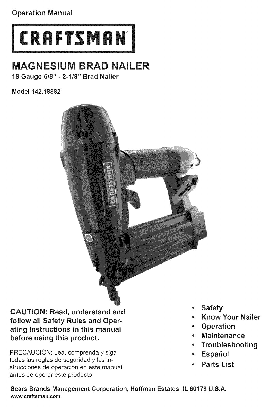
MAGNESIUM BRAD NAILER
t8 Gauge 518"-2-118" Brad Nailer
Model 142.18882
CAUTION: Read, understand and
• Safety
• KnowYour Nailer
follow all Safety Rules and Oper-
ating Instructions in this manual
before using this product.
PRECAUCION: Lea, comprenda y siga
todas las reglas de seguridad y las in-
strucciones de operaci6n en este manual
antes de operar este producto
Sears Brands Management Corporation, Hoffman Estates, IL 60179 U.S.A.
www.craftsman.com
• Operation
• Maintenance
• Troubleshooting
• Espa_ol
• Parts List
Warranty ...................................................................... 2
Safety Instructions ...................................................... 2
Know Your Nailer ......................................................... 3
Operation ................................................................. 4-6
Maintenance ............................................................ 6-7
Troubleshooting ........................................................... 7
Espa_ol .................................................................. 8-13
Parts and Illustrations List......................................... 14
CRAFTSMAN ONE YEAR FULL WARRANTY
FOR ONE YEAR from the date of purchase, this
product is warranteed against any defects in material
or workmanship. A defective product will be replaced
free of charge.
For warranty coverage details to obtain free re-
placement, visit the web site: www.craftsman.com
This ONE YEAR warranty is void if this product is
ever used while providing commercial services or if
rented to another person. For 90 DAY commercial
use terms, see listing on Craftsman warranty web
page. This warranty gives you specific legal rights,
and you may also have other rights which vary from
state to state.
Sears Brands Management Corp. Hoffman Es-
tates, IL 60179
• Read and follow all safety rules and operating
instructions in this manual and on warning label of
tool before using this tool. Failure to follow warnings
could result in DEATH or SERIOUS INJURY. Keep
this manual with the tool.
• Keep work area clean and properly lighted.
• Keep children, bystanders and visitors at a safe
distance from work area while operating this tool.
• Air tool operators and all others in work area MUST
always wear safety goggles complying with the
United States ANSI Z87.1 to prevent eye injury from
fasteners and flying debris when loading, operating
and unloading this tool. Everyday eyeglasses have
only impact resistant lenses. These are NOT safety
glasses. ANSI Z87.1 safety glasses have perma-
nently attached rigid, hard plastic side shields and
will have "Z87.1" printed or stamped on them.
• Always wear ear protection. The work area may
include exposure to excessive noise levels which
will require necessary ear protection. Some envi-
ronments will require head protection: use head
protection conforming to ANSI Z89.1.
Do not alter or modify this tool in any way. Do not
use this tool for any application other than for which
it was designed.
Do not use oxygen, carbon dioxide, high-pressure
compressed gas or bottled gases as the power
source for this tool. The tool will explode and seri-
ous personal injury could result.
Never connect the tool to air pressure which could
potentially exceed 200 PSI. Use only clean, dry
regulated air within rated range as marked on tool.
The tool must have a male, free-flow hose coupling
so that all air pressure is removed from the tool
when the coupling joint is disconnected. Failure to
use proper coupling could cause accidental dis-
charge, possibly causing injury.
• Only use air hose that is rated for maximum work-
ing pressure of 150 PSI or 150% of the maximum
system pressure, whichever is greater.
• Do not pull trigger or depress contact trip while
connecting to the air supply, as the tool may cycle,
possibly causing injury.
• When loading the tool, do not pull trigger or de-
press contact trip. Do not point the tool at yourself
or others. Do not place hand or any part of body in
the fastener discharge area of the tool as accidental
actuation may occur and cause injury.
• Disconnect tool from air supply before loading or
unloading, performing tool maintenance, clearing
a jammed fastener, leaving work area, moving tool
to another location or handing the tool to another
person.
• Use only the size and type of fasteners designated
in the Specifications list in this manual.
• Do not load the tool until you are ready to use it.
• Always assume that the tool contains fasteners.
Keep the tool pointed away from yourself and others
at all times. Never engage in horseplay. Never pull
the trigger unless the contact trip is in contact with
the workpiece. Keep others at a safe distance from
the tool while the tool is in operation.
• Always remove finger from trigger when not driving
fasteners to avoid accidental firing. Never carry the
tool with finger on or under the trigger as accidental
actuation may occur and cause injury.
• Always keep hands and body away from the fas-
tener discharge area when air supply is connect-
ed to the tool. Grip tool firmly to maintain control
while allowing tool to recoil away from work surface
as fastener is driven. If contact trip is allowed to
recontact work surface before trigger is released, an
unwanted fastener may be driven.
• Check operation of the contact trip frequently. Nev-
er use the tool if the contact trip, trigger or springs
have become inoperable, missing or damaged. Do
not alter or remove contact trip, trigger or springs.
Never use a tool that is leaking air, has missing or
damaged parts, or requires repair.
• Never drive fasteners on top of other fasteners or
with the tool at too steep an angle. The fasteners
can ricochet and cause injury. Do not drive fasten-
ers close to the edge of the work piece. The work-
piece is likely to split, allowing the fastener to fly free
and cause injury. Do not attempt to drive fasteners
into hard or brittle materials such as concrete, steel
or tile.
• Do not overreach. Always place yourself in a firmly
balanced position when using or handling the tool.
Do not attach the hose or tool to your body.
• Do not operate tool without fasteners or damage to
tool may result.
• Do not use tool without safety warning label. If
label is missing, damaged or unreadable, contact
1-800-469-4663 to obtain a new label.
• Only qualified repair personnel must perform tool
service.
• When servicing a tool, use only identical repair
parts.
• Store tool out of reach of children and other un-
trained persons.
WARNING: Some dust created by using power tools
contains chemicals known to the State of California to
cause cancer and birth defects or other reproductive
harm.
2
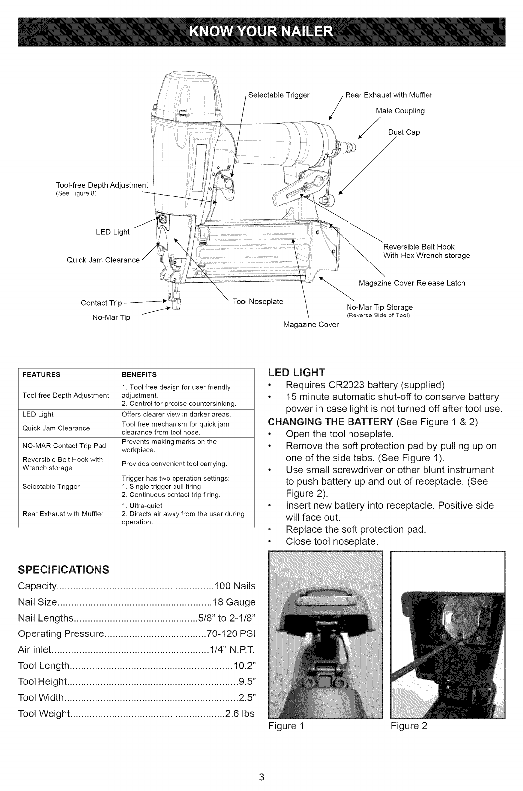
Tool-free Depth Adjustment
(See Figure 8)
LED Light
Quick Jam
Selectable Trigger
Rear Exhaust with MufflerMale Coupling
Dust Cap
Reversible Belt Hook
With Hex Wrench storage
Magazine Cover Release Latch
Tool Noseplate
FEATURES BENEFITS
Tool-free Depth Adjustment adjustment.
LED Light Offers clearer view in darker areas.
Quick Jam Clearance
NO-MAR Contact Trip Pad
Reversible Belt Hook with
Wrench storage
Selectable Trigger 1. Single trigger pull firing.
Rear Exhaust with Muffler 2. Directs air away from the user during
1. Tool free design for user friendly
2. Control for precise countersinking.
Tool free mechanism for quick jam
clearance from tool nose.
Prevents making marks on the
workpiece.
Provides convenient tool carrying.
Trigger has two operation settings:
2. Continuous contact trip firing.
1. Ultra-quiet
operation.
SPECIFICATIONS
Capacity ......................................................... 100 Nails
Nail Size ........................................................ 18Gauge
Nail Lengths ............................................. 5/8" to 2-1/8"
Operating Pressure ..................................... 70-120 PSI
Air inlet ......................................................... 1/4" N.P.T,
No-Mar Tip Storage
(Reverse Side of Tool)
Magazine Cover
LED LIGHT
• Requires CR2023 battery (supplied)
• 15 minute automatic shut-off to conserve battery
power in case light is not turned off after tool use.
CHANGING THE BATTERY (See Figure 1 & 2)
• Open the tool noseplate.
• Remove the soft protection pad by pulling up on
one of the side tabs. (See Figure 1).
• Use small screwdriver or other blunt instrument
to push battery up and out of receptacle. (See
Figure 2).
• Insert new battery into receptacle. Positive side
will face out.
• Replace the soft protection pad.
• Close tool noseplate.
Tool Length ........................................................... 10.2"
Tool Height .............................................................. 9.5"
Tool Width ............................................................... 2.5"
Tool Weight ........................................................ 2.6 Ibs
Figure 1 Figure 2
DESCRIPTION
TheCraftsman18gaugeBradNailerdrivesbrads
from5/8"to2-1/8"long.Oillessdesigneliminates
dailyoilingandoilstainsonworkpiece.Diecastmag-
nesiumbodywithtexturedrubbergripminimizesop-
eratorfatigue.Largecapacity,sideloadingmagazine
withpositive,quickactionlatchmakesloadingeasy.
Nailerfeaturesrearexhaust,singlerapid-fireoper-
ation,adjustabledepthofdrivecontrol,no-martip
andstoragecase.Safetyfeaturedisablestoolunless
contacttipispressedagainstworkpiece.Tapered
toolnoseprovidesoperatorwithgreatervisibilityfor
precisefastnerplacement.Rigidtoolnosereduces
jamming.The18GuageBradNailerisexcellentfor
molding,furnituremakingandpictureframing.
AIRSUPPLYLINE
SeeFigure3
DANGER:Donotuseoxygen,carbondioxide,
high-pressurecompressedgasorbottledgasesas
thepowersourceforthistool.Thetoolwillexplode
andseriouspersonalinjurycouldresult.
• Theairtooloperatesoncompressedairatpres-
suresfrom70-120PSI
• Neverconnectthetooltoairpressurewhich
couldpotentiallyexceed 200 PSI. Use only
clean, dry, regulated air within rate range as
marked on tool.
Air delivery Required: 0.94 SCFM @ 90 PSI. (30
shots per minute).
WARNING: Keep hands and body away from
discharge area of tool when connecting air supply.
Always disconnect tool from air supply when servic-
ing or adjusting tool and when tool is not in use.
• Air operated tools require clean, dry, lubricated
compressed air to ensure top performance, low
maintenance and long life.
• Dirt and abrasive materials present in all air lines
will damage tool O-rings, valves and cylinders.
• Moisture will reduce tool performance and life if
not removed from compressed air.
• The air supply system must be able to provide
air pressure of 70-120 pounds per square inch at
tool.
• All hoses and pipes in the air supply system must
be clean and free of moisture and foreign parti-
cles. Hoses must be rated for maximum working
pressure of 150 PSI or 150% of maximum system
pressure, whichever is greater.
• Do not mount swivel connector in air supply line.
• The air pressure should be properly regulated.
• Different workpiece materials and different
fastener lengths will require different operating
pressure.
• Be sure all connections in air supply system are
sealed to prevent air loss.
WARNING: This tool is equipped with a male, free-
flow coupling for air supply connection. To prevent
accidental discharge and possible injury, NEVER
remove the male coupling to replace with afemale
coupling.
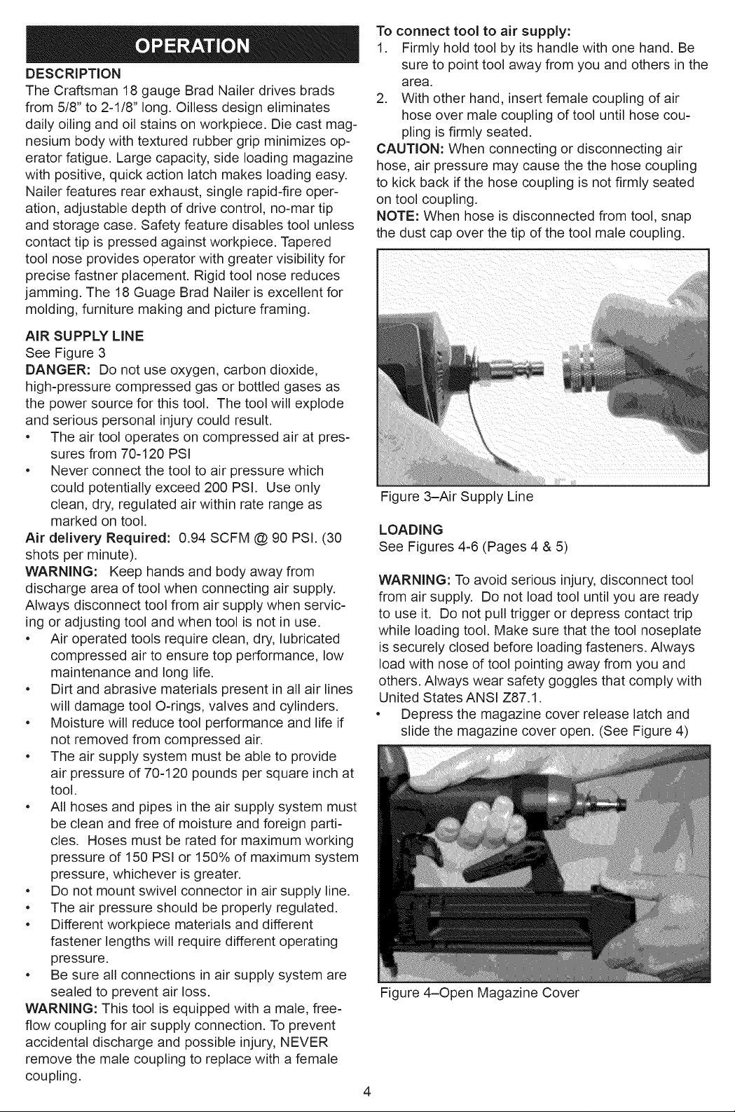
To connect tool to air supply:
1. Firmly hold tool by its handle with one hand. Be
sure to point tool away from you and others in the
area.
2. With other hand, insert female coupling of air
hose over male coupling of tool until hose cou-
pling is firmly seated.
CAUTION: When connecting or disconnecting air
hose, air pressure may cause the the hose coupling
to kick back if the hose coupling is not firmly seated
on tool coupling.
NOTE: When hose is disconnected from tool, snap
the dust cap over the tip of the tool male coupling.
Figure 3-Air Supply Line
LOADING
See Figures 4-6 (Pages 4 & 5)
WARNING: To avoid serious injury, disconnect tool
from air supply. Do not load tool until you are ready
to use it. Do not pull trigger or depress contact trip
while loading tool. Make sure that the tool noseplate
is securely closed before loading fasteners. Always
load with nose of tool pointing away from you and
others. Always wear safety goggles that comply with
United States ANSI Z87.1.
• Depress the magazine cover release latch and
slide the magazine cover open. (See Figure 4)
Figure 4-Open Magazine Cover
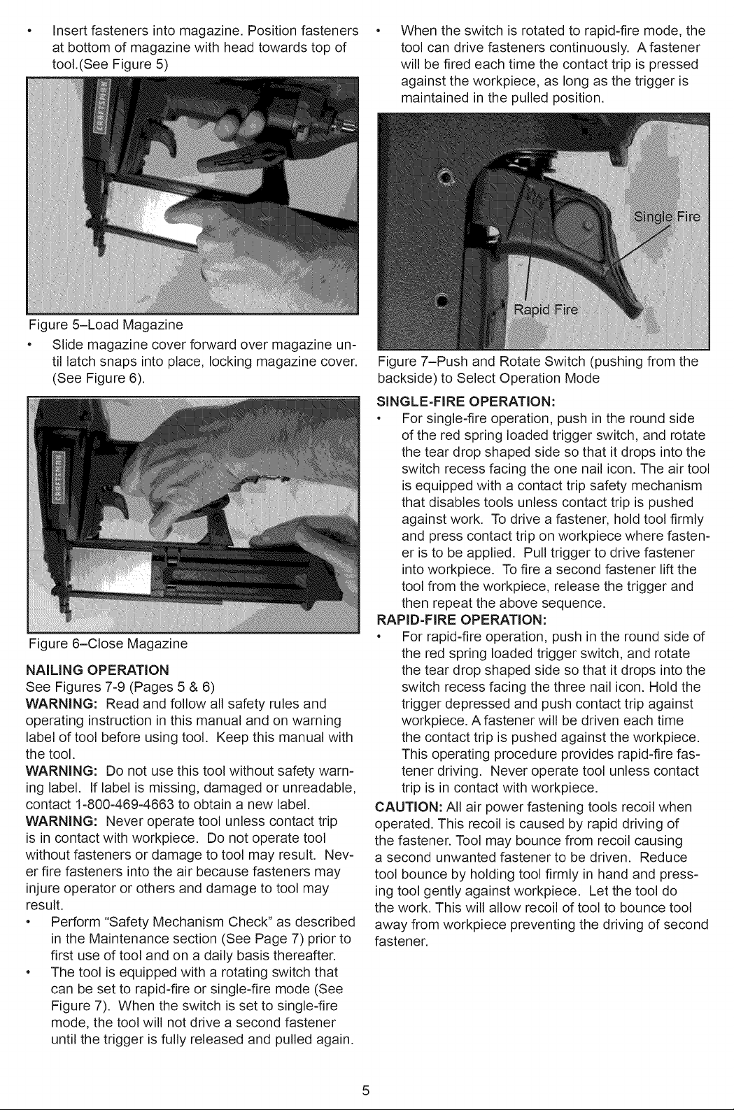
Insertfastenersintomagazine.Positionfasteners
atbottomofmagazinewithheadtowardstopof
tool.(SeeFigure5)
Figure5-LoadMagazine
• Slidemagazinecoverforwardovermagazineun-
tillatchsnapsinto3lace,lockingmagazinecover.
(SeeFigure6).
Figure6-CloseMagazine
NAILINGOPERATION
SeeFigures7-9(Pages5&6)
WARNING:Readandfollowallsafetyrulesand
operatinginstructioninthismanualandonwarning
labeloftoolbeforeusingtool.Keepthismanualwith
thetool.
WARNING:Donotusethistoolwithoutsafetywarn-
inglabel.Iflabelismissing,damagedorunreadable,
contact1-800-469-4663toobtaina newlabel.
WARNING:Neveroperatetoolunlesscontacttrip
isincontactwithworkpiece.Donotoperatetool
withoutfastenersordamagetotoolmayresult.Nev-
erfirefastenersintotheairbecausefastenersmay
injureoperatororothersanddamagetotoolmay
result.
• Perform"SafetyMechanismCheck"asdescribed
intheMaintenancesection(SeePage7)priorto
firstuseoftoolandona dailybasisthereafter.
• Thetoolisequippedwitharotatingswitchthat
canbesettorapid-fireorsingle-firemode(See
Figure7). Whentheswitchissetto single-fire
mode,thetoolwillnotdriveasecondfastener
untilthetriggerisfullyreleasedandpulledagain.
Whentheswitchisrotatedtorapid-firemode,the
toolcandrivefastenerscontinuously.Afastener
willbefiredeachtimethecontacttripispressed
againsttheworkpiece,aslongasthetriggeris
maintainedinthepulledposition.
Figure7-PushandRotateSwitch(pushingfromthe
backside)toSelectOperationMode
SINGLE-FIREOPERATION:
• Forsingle-fireoperation,pushintheroundside
oftheredspringloadedtriggerswitch,androtate
theteardropshapedsidesothatitdropsintothe
switchrecessfacingtheonenailicon.Theairtool
isequippedwitha contacttripsafetymechanism
thatdisablestoolsunlesscontacttripispushed
againstwork.Todriveafastener,holdtoolfirmly
andpresscontacttriponworkpiecewherefasten-
eristobeapplied.Pulltriggertodrivefastener
intoworkpiece.Tofireasecondfastenerliftthe
toolfromtheworkpiece,releasethetriggerand
thenrepeattheabovesequence.
RAPID-FIREOPERATION:
• Forrapid-fireoperation,pushintheroundsideof
theredspringloadedtriggerswitch,androtate
theteardropshapedsidesothatitdropsintothe
switchrecessfacingthethreenailicon.Holdthe
triggerdepressedandpushcontacttripagainst
workpiece.Afastenerwillbedriveneachtime
thecontacttripispushedagainsttheworkpiece.
Thisoperatingprocedureprovidesrapid-firefas-
tenerdriving.Neveroperatetoolunlesscontact
tripisincontactwithworkpiece.
CAUTION:Allairpowerfasteningtoolsrecoilwhen
operated.Thisrecoiliscausedbyrapiddrivingof
thefastener.Toolmaybouncefromrecoilcausing
asecondunwantedfastenerto bedriven.Reduce
toolbouncebyholdingtoolfirmlyinhandandpress-
ingtoolgentlyagainstworkpiece.Letthetooldo
thework.Thiswillallowrecoiloftooltobouncetool
awayfromworkpiecepreventingthedrivingofsecond
fastener.
5
 Loading...