

Page 1

°1
10" TABLE SAW
WITH FOLDABLE STAND
Model No.
141.142580
• Safety
• Unpacking
CAUTION:
Read and follow all Safety
Rules and Operating
Instructions before First
Use of this Product. Keep
this Manual with Tool.
Sears Brands Management Corp., Hoffman Estates, IL 60179 U.S.A.
www.craftsman,com
142580,01 Draft (01/01/14)
° Assembly
° Operation
=Maintenance
• Parts List
= Espahol
Page 2
Warranty .......................................... 2
Safety Rules ................................ 2-4
Unpacking ...................................... 4-6
Assembly ..................................... 7-16
Installation .................................... 18-19
Operation .................................... 19-27
Maintenance ................................... 27-29
Troubleshooting .................................. 31
Repair Protection Agreement ....................... 32
Parts Illustration and List ........................ 33-44
Espa_ol ...................................... 45_78
CRAFTSMAN ONE YEAR LIMITED WARRANTY
FOR ONE YEAR from the date d purchase, this product
is warranted against defects in material or workmanship. With
proof of purchase, a defective product will receive free repair or
replacement at option of seller.
For warranty coverage details to obtain free replacement,
visit the web page: ww.w.craftsman,comlwarranty
This warranty' do_ notcover the blade or belt, which are expendable
parts that can wear out from normal use within the warranty period.
This ONE YEAR warranty is void if this product is ever used while
providing commercial services or if rented to another person.
For 90 DAY commercial and rental use terms; see the Craftsman
warranty web page.
This warranty gives you specific legal rights, and you may also
have other rights which vary from state to state.
Sears Brands Management Corporation, Hoffman Estates,
IL 60179
WARNING: Read and understand all instructions.
Failure to follow all instructions listed below, may result in electric
shock, fire and/or serious personal injury.
GENERAL SAFETY RULES
PROPOSITION 65 WARNING: Some dust created by using
power tools contain chemicals known to the state of California
to cause cancer, birth defects or other reproductive harm.
Some examples of these chemicals are:
- Lead from lead-based paints
° Crystalline silica from bricks and cement and other masonry
products.
o Arsenic and chromium from chemically-treated lumber.
Your risk from these exposures vary, depending on how often
you do this type of work. To reduce your exposure to these
chemicals: work in a wel! ventilated area and work with approved
safety equipment. Always wear OSHA/NIOSH approved, properly
fitting face mask or respirator when using such tools.
CAUTION: Always follow proper operating procedures as
defined in this manual--even if you are familiar with use
of this or similar tools. Remember that being careless for even
a fraction of a second can result in severe personal injury.
Sears Brands Management Corporation
WARNING: THIS PRODUCT CONTAINS LE.AD A CHEMICAL
KNOWN TO THE STATE OF CALIFORNIA TO CAUSE CANCER
AND BIRTH DEFECTS OR OTHER REPRODUCTIVE HARM.
WASH HANDS AFTER HANDLING.
o KNOW YOUR POWER TOOL. Read the operator's manual
carefully: Learn the saw's applications and limitations as ,well
as the specific potential hazards related to this tool.
• GUARD AGAINST ELECTRICAL SHOCK BY PREVENTING
BODY CONTACT WiTH GROUNDED SURFACES. For
example, pipes, radiators, ranges, refrigerator enclosures,
° KEEP GUARDS IN P_CE and in good working order.
° REMOVE ADJUSTING KEYS AND WRENCHES. Form habit
of checking to see that keys and adjusting wrenches are
removed from tool before _rning it on.
° KEEP WORK AREA CLEAN. Clu_ered areas and benches
invite accidents. DO NOT leave tools or pieces of wood on
the saw while it is in operation.
° DO NOT USE IN DANGEROUS ENVIRONMENTS. Do not
use power tools in damp or wet locations or expose to rain.
Keep the work area well lit.
° KEEP CHILDREN AND VISITORS AWAY. All visitors should
wear safety glasses and be kept a safe distance from work
area. Do not let visitors contact tool or extension cord while
operating.
° MAKE WORKSHOP CHILDPROOF ,withpadlo_s and master
switches, or by removing starter keys:
• DON'T FORCE TOOL. It wil! do the job better and safer at
the feed rate for which it was designed.
• USE RIGHT TOOL. Don't force the tool or attachment to do
a job it was not designed for. Don't use it for a purpose not
intended.
• USE THE PROPER EXTENSION CORD. Make sure your
extension cord is in good condition. Use only a cord heavy
enough to carry the current your product will draw. An
undersized cord will cause a drop in line voltage resulting in
loss of power and overheating, A wire gauge size (A.W.G.)
of at least 14 is recommended for an extension cord 25 feet
or less in length. If in doubt, use the next heavier gauge. The
smaller the gauge number, the heavier the cord.
• DRESS PROPERLY. Do not wear loose clothing, gloves,
neckties, or jewelry. They can get caught and draw you into
moving parts Rubber gloves and nonskid footwear are
recommended when working outdoors. Also wear protective
hair covering to contain long hair.
• ALWAYS wear safety goggles that comply with United States
ANSI Z87.1 and a face shield or dust mask if operation is
dusty:Everyday eyeglasses have only impact_resistant lenses,
they are NOT safety glasses.
o SECURE WORK. Use a featherboard to hold work when
practical. It's safer than using your hand and frees both hands
to operate toot.
o DON'T OVERREACH. Keep proper footing and balance at
all times.
• MAINTAIN TOOLS WITH CARE, Keep tools sharp and clean
for better and safer performance. Follow instructions for
lubricating and changing accessories,
° DISCONNECT TOOLS. When not in use, before servicing,
or when changing attachments, blades, bits, cutters, etc, all
tools should be disconnected.
° AVOID ACCIDENTAL STARTING. Be sure switch is off when
plugging in any tool.
2
Page 3

° USERECOMMENDEDACCESSORIES.Consulttheoperator's
manualforrecommendedaccessories.Theuseofimproper
accessoriesmayriskinjury.
° NEVERSTANDONTOOL.Seriousinjurycouldoccurif the
tool is tipped or if the cutting tool is unintentionally contacted.
° CHECK DAMAGED PARTS. Before further use of the tool,
a guard or other part that is damaged should be carefully
checked to determine that it will operate properly and perform
its intended function. Check for alignment of moving parts,
binding of moving parts, breakage of parts, mounting and
any other conditions that may affect its operation. A guard or
other part that is damaged must be propedy repaired
or replaced by an authorized service center to avoid risk of
personal injury.
° USE THE RIGHT DIRECTION OF FEED. Feed work into a
blade or cutter against the direction of rotation of blade or
cutter only.
• NEVER LEAVE TOOL RUNNING UNATTENDED. TURN
THE POWER OFF. Don't leave tool until itcomes to a complete
stop.
• PROTECT YOUR LUNGS. Wear a face or dust mask if the
cutting operation is dusty.
° PROTECT YOUR HEARING. Wear ear plugs or muffs during
extended periods of operation.
° DO NOT ABUSE CORD. Never yank cord to disconnect from
receptacle. Keep cord away from heat. oil. and sharp edges
= WHEN OPERATING A POWER TOOL OUTSIDE, USE AN
OUTDOOR EXTENSION CORD MARKED "W-A" OR "W".
These cords are rated for outdoor use and reduce the risk of
electric shock.
• ALWAYS KEEP THE BLADE GUARD AND SPREADER
(RIVING KNIFE) IN PLACE and in working oraer.
° KEEP BLADES CLEAN, SHARP, AND WITH SUFFICIENT
SET. Sharp blades minimize stalling and kickback.
° KEEP HANDS AWAY FROM CUTTING AREA. Keep hands
away from blades. Do not reach underneath work or around
or over the blade while blade is rotating. Do not attempt to
remove cut material when blade is moving.
• BLADE COASTS AFTER BEING TURNED OFF.
° NEVER USE IN AN EXPLOSIVE ATMOSPHERE. Normal
sparking of the motor could ignite fumes
° ISPECT TOOL CORDS PERIODICALLY. If damaged, have
repaired by a qualified service technician at an authorized
service facility. The conductor with insulation having an outer
sudace that is green with or without yellow stripes is the
equipment-grounding conductor. If repair or replacement of
the electric cord or plug is necessary, do not connect the
equipment*grounding conductor to a live terminal. Repair or
replace a damaged or worn cord immediately. Stay constantly
aware of cord location and keep it well away from the rotating
blade.
° INSPECT EXTENSION CORDS PERIODICALLY and replace
if damaged
° GROUND ALL TOOLS. If tool is equipped with three-prong
plug, it should be plugged into a three-hole electrical
receptacle.
° CHECK WITH A QUALIFIED ELECTRICIAN or service
personnel if the grounding instructions are not completely
understood or if in doubt as to whether the tool is propedy
grounded.
° USE ONLY CORRECT ELECTRICAL DEVICES: 3*wire
extension cords that have 3-prong grounding plugs and 3-pole
receptacles that accept the tool's plug.
° DO NOT MODIFY the p!ug provided. If it will not fit the outlet,
have the proper outlet installed by a qualified electrician.
° KEEP TOOL DRY, CLEAN, AND FREE FROM OIL AND
GREASE. Always use a clean cloth when cleaning, Never
use brake fluids, gasoline, petroleum-based products, or any
solvents to clean tool.
° STAY ALERT AND EXERCISE CONTROL. Watch what you
are doing and use common sense. Do not operate tool when
you are tired, Do not rush.
° DO NOT USE TOOL IF SWITCH DOES NOT TURN IT ON
AND OFF, Have defective switches replaced by an authorized
service center.
° USE ONLY CORRECT BLADES. Do not use blades with
incorrect size holes. Never use blade washers or blade bolts
that are defective or incorrect. The maximum blade capac_y
of your saw is 10 in.
° BEFORE MAKING A CUT, BE SURE ALL ADJUSTMENTS
ARE SECURE.
° BE SURE BLADE PATH IS FREE OF NAILS. Inspect for
and remove all nails from lumber before cutting
° NEVER TOUCH BLADE or other moving parts during use.
° NEVER START A TOOL WHEN ANY ROTATING
COMPONENT IS IN CONTACT WITH THE WORKPIECE,
° DO NOT OPERATE A TOOL WHILE UNDER THE INFLUENCE
OF DRUGS, ALCOHOL, OR ANY MEDICATION.
° WHEN SERVICING use only identical replacement parts. Use
of any other parts may create a hazard or cause product
damage.
° USE ONLY RECOMMENDED ACCESSORIES listed in this
manual or addendums. Use of accessories that are not listed
may cause the dsk of personal injury. Instructions for safe
use of accessories are included with the accessory.
° DOUBLE CHECK ALL SETUPS. Make sure blade is tight
and not making contact with saw or workpiece before
connecting to power supply.
SPECIFIC SAFE_ RULES
° FIRMLY BOLT THE SAW TO A WORK BENCH OR LEG
STAND at approximately hip height.
° NEVER OPERATE THE SAW ON THE FLOOR.
• KEEP GUARDS IN PLACE and in good working order,
° GUARD AGAINST KICKBACK. Kickback occurs when the
blade stalls rapidly and workpiece is driven back towards the
operator: It can pult your hand into the blade resulting
in serious personal injury. Stay out of blade path and turn
switch off immediately' if blade binds or stalls.
° USE RIP FENCE. Always use a fence or straight edge guide
when ripping.
° SUPPORT LARGE PANELS. To minimize risk of blade
pinching and kickback, always support large panels,
• REMOVE ALL FENCES AND AUXILIARY TABLES before
transporting saw. Failure to do so can result in an accident
causing possible serious personal injury.
• DON'T OVERREACH. Keep proper footing and balance at
all times.
• NEVER place arms or hands in line with the path of the
cutting blade.
° ALWAYS USE BLADE GUARD, RIVING KNIFE, AND
3
Page 4
ANTI-KICKBACK PAWLS on all '_through-sawing" operations.
Through-sawing operations are those in which the blade cuts
completely through the workpiece as in ripping or cross
curing. Keep the blade guard down, the anti-kickback pawls
down, and the spreader in place over the blade.
• ALWAYS SECURE WORK firmly against the rip fence or
miter gauge. NEVER use the dp fence during the same
operation as the miter gauge.
° ALWAYS USE A PUSH STICK FOR RIPPING NARROW
STOCK. A push stick is a device used to push a workpiece
through the blade instead of using your hands. Size and shape
can vary but the push stick must always be narrower than
the workpiece to prevent the push stick from contacting the
saw blade. When ripping narrow stock, always use a push
stick, so your hand does not come close to the saw blade,
Use a featherboard and push blocks for non4hrough cuts.
° NEVER perform any operation "freehand" which means using
only your hands to support or guide the workpiece. Always
use either the np fence or miter fence to position and guide
the work.
° NEVER stand or have any part of your body in line with the
path of the saw blade.
° NEVER reach behind, over, or within three inches of the blade
or cutter with either hand for any reason.
° MOVE THE RIP FENCE out of the way when cross cutting.
° DO NOT USE THE MITER GAUGE AND RIP FENCE during
the same operation.
° NEVER attempt to free a stalled saw blade without first turning
the saw OFF and disconnecting the saw from the power
source.
° PROVIDE ADEQUATE SUPPORT to the rear and sides of
the saw table for wide or _ongwork pieces.
• AVOID KICKBACKS (work thrown back toward you) by:
a) Keeping blade sharp.
b) Keeping rip fence parallel to the saw blade,
c) Keeping spreader, anti-kickback pawls, and blade guard
in place and operating.
d) Not releasing the work before it is pushed all the way past
the saw blade using a push stick.
e) Not ripping work that is twisted or warped or does not have
a straight edge to guide along the fence.
• IF THE POWER SUPPLY CORD IS DAMAGED, it must be
replaced only by the manufacturer or by an authonzed service
center to avoid risk.
• AVOID AWKWARD OPERATIONS AND HAND POSITIONS
where a sudden slip could cause your hand to move into the
cutting tool.
• USE ONLY RECOMMENDED ACCESSORIES listed in this
manual or addendums. Use of accessones that are not listed
may cause the risk of personal injury. Instructions for safe
use of accessories are included with the accessory.
• MAKE SURE THE WORK AREA HAS AMPLE LIGHTING
to see the work and that no obstructions will interfere with
safe operation BEFORE performing any work using the table
saw,
° ALWAYS TURN OFF SAW before disconnecting it, to avoid
accidental starting when reconnecting to power supply:
° SAVE THESE INSTRUCTIONS. Refer to them frequently
and use to instruct other users. If you loan someone this tool,
loan them these instructions also.
THINK SAFETY
Safety is a combination of operator common sense and alertness
at all times when the saw is being used.
CAUTION: Follow safety instructions that appear on the front
of your saw.
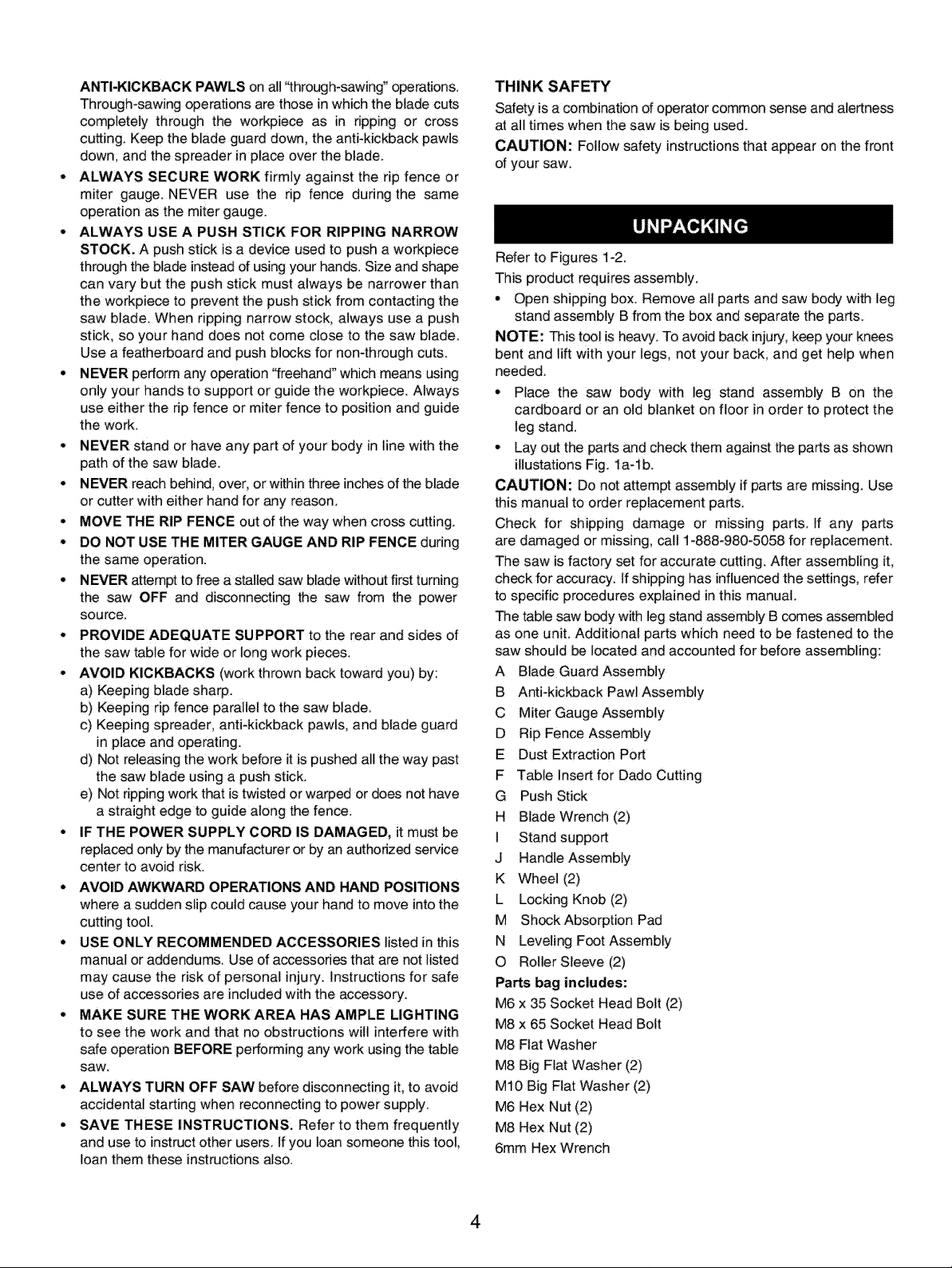
Refer to Figures 1-2.
This product requires assembly.
° Open shipping box. Remove all parts and saw body with leg
stand assembly B from the box and separate the parts.
NOTE: This tool is heavy: To avoid back injury, keep your knees
bent and lift with your legs, not your back, and get help when
needed
o Place the saw body with leg stand assembly B on the
cardboard or an old blanket on floor in order to protect the
leg stand.
o Lay o_ the parts and check them against the parts as shown
iliustations Fig. 1a-lb.
CAUTION: Do not attempt assembly if parts are missing. Use
this manual to order replacement parts.
Check for shipping damage or missing parts. If any parts
are damaged or missing, call 1-888-980-5058 for replacement.
The saw is factory set for accurate cutting. After assembling it,
check for accuracy: If shipping has influenced the settings, refer
to specific procedures explained in this manual.
The table saw body with leg stand assembly B comes assembled
as one unit. Additional parts which need to be fastened to the
saw should be located and accounted for before assembling:
A Blade Guard Assembly
B Anti-kickback Pawl Assembly
C Miter Gauge Assembly
D Rip Fence Assembly
E Dust Extraction Port
F Table Insert for Dado Cutting
G Push Stick
H Blade Wrench (2)
I Stand support
J Handle Assembly
K Wheel (2)
L Locking Knob (2)
M Shock Absorption Pad
N Leveling Foot Assembly
O Roller Sleeve (2)
Parts bag includes:
M6 x 35 Socket Head Bolt (2)
Max 65 Socket Head Bolt
M8 Flat Washer
M8 Big Flat Washer (2)
M10 Big Flat Washer (2)
M6 Hex Nut (2)
M8 Hex Nut (2)
6mm Hex Wrench
4
Page 5
A
D E
G H
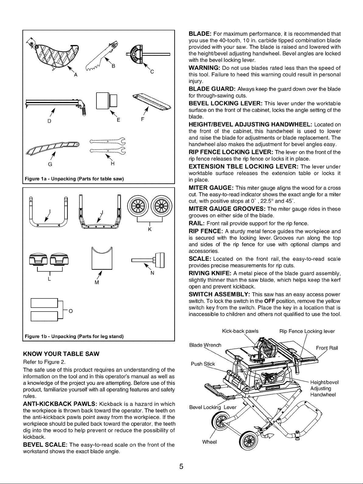
Figurela * Unpacking (Partsfor table saw)
I I
I N
L
M
F
I i I
K
BLADE: For maximum performance, it is recommended that
you use the 404ooth, 10 in. carbide tipped combination blade
provided with your saw. The blade is raised and lowered with
the height/bevel adjusting handwheel. Bevel angles are locked
with the bevel locking lever.
WARNING: Do not use blades rated less than the speed of
this tool. Failure to heed this warning could result in personal
injury.
BLADE GUARD: Always keep the guard down over the blade
for through-sawing cuts.
BEVEL LOCKING LEVER: This lever under the worktable
surface on the front of the cabinet, locks the angle setting of the
blade.
HEIGHT/BEVEL ADJUSTING HANDWHEEL: Located on
the front of the cabinet, this handwheel is used to lower
and raise the blade for adjustments or blade replacement. The
handwheel also makes the adjustment for bevel angles easy.
RIP FENCE LOCKING LEVER: The lever onthe front of the
tip fence releases the rip fence or locks it in place.
EXTENSION TBLE LOCKING LEVER: The lever under
worktable surface releases the extension table or locks it
in place.
MITER GAUGE: This miter gauge aligns the wood for a cross
cut. The easy-to-read indicator shows the exact angle for a miter
cut, with positive stops at 0° , 22.5 ° and 45°.
MITER GAUGE GROOVES: The miter gauge rides in these
grooves on either side of the blade.
RAIL: Front rail provide support for the rip fence,
RIP FENCE: A sturdy metal fence guides the workpiece and
is secured with the locking lever: Grooves run along the top
and sides of the rip fence for use with optional clamps and
accessories.
SCALE: Located on the front rail, the easy4o-read scale
provides precise measurements for rip cut&
RIVING KNIFE: A metal piece of the blade guard assembly,
slightly thinner than the saw blade, which helps keep the kerf
open and prevent kickJoack.
SWITCH ASSEMBLY: This saw has an easy access power
switch. To Iockthe switch in the OFF position, remove the yellow
switch key from the switch, Place the key in a location that is
inaccessible to children and others not qualified to use the tool.
Figure lb - Unpacking (Parts for leg stand)
KNOW YOU R TABLE SAW
Refer to Figure 2.
The safe use of this product requires an understanding of the
information on the tool and in this operator's manual as well as
a knowledge of the project you are attempting. Before use of this
product,familiarize yourself with all operating features and safety
rules.
ANTI-KICKBACK PAWLS: Kickback is a hazard in which
the workpiece is thrown back toward the operator. The teeth on
the anti-kickback pawls point away from the workpiece. If the
work,piece should be pulled back toward the operator, the teeth
dig into the wood to help prevent or reduce the possibility of
kickback.
BEVEL SCALE: The easy-to-read scale on the front of the
workstand shows the exact blade angle.
Kick-backpawls Rip Fence Locking lever
Blade Wrench
-_-.._.. Front Rail
Push Stick
Adjusting
Handwheel
Bevel Locking Lever
Wheel
5
Page 6
Miter Gauge
Switch
Overload Reset
Switch
Blade guard
Saw Blade
Fence
(tension Table
Locking Lever
Locking Knob
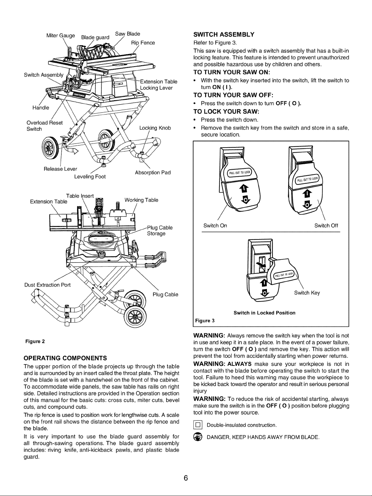
SWITCH ASSEMBLY
Refer to Figure 3
This saw is equipped with a switch assembly that has a built-in
locking feature, This feature is intended to prevent unauthorized
and possible hazardous use by children and others.
TO TURN YOUR SAW ON:
• With the switch key inserted into the switch, lift the switch to
tum ON ( I ).
TO TURN YOUR SAW OFF:
• Press the switch down to turn OFF ( O ).
TO LOCK YOUR SAW:
• Press the switch down,
° Remove the switch key from the switch and store in a safe,
secure location,
Release Lever
Leveling Foot
Absorption Pad
Table Insert
Extension Table \\
Dust Extraction Port
Figur_ 2
Working Table
Cable
Storage
Plug Cable
OPERATING COMPONENTS
The upper portion of the blade projects up through the table
and is surrounded by an insert called the throat plate; The height
of the blade is set with a handwheel on the front of the cabinet.
To accommodate wide panels, the saw table has rails on right
side. Detailed instructions are provided in the Operation se_ion
of this manual for the basic cuts: cross cuts, miter cuts; beve!
cuts, and compound cuts.
The rip fence is used to position work for lengthwise cuts. A scale
on the front rail shows the distance between the rip fence and
the blade.
It is very important to use the blade guard assembly for
all through-sawing operations. The blade guard assembly
includes: nving knife, anti-kickback pawls, and plastic blade
guard.
/
Switch On Switch Off
ch Key
Switch in Locked Position
Figure 3
WARNING: Always remove the switch key when the tool is not
in use and keep it in a safe place. In the event of a power failure,
turn the switch OFF ( O ) and remove the key. This action will
prevent the tool from accidentally starting when power returns.
WARNING: ALWAYS make sure your workpiece is not in
contact with the blade before operating the switch to start the
tool. Failure to heed this warning may cause the workpiece to
be kicked back toward the operator and result in serious personaJ
injury
WARNING: To reduce the risk of accidental starting, always
make sure the switch is in the OFF ( O ) position before plugging
tool into the power source.
Double-insulated construction.
DANGER, KEEP HANDS AWAY FROM BLADE.
6
Page 7
Refer to Figures 4-42.
CAUTION: Do not attempt assembly if parts are missing. Use
this manual to order replacement parts.
Be certain all parts are clean and free of shipping preservative.
Also, completely remove all parts of packing.
WARNING: Do not connect the plug to the outlet until all
installations and adjustments have been completed and you
have read and understood the safety and operational instructions.
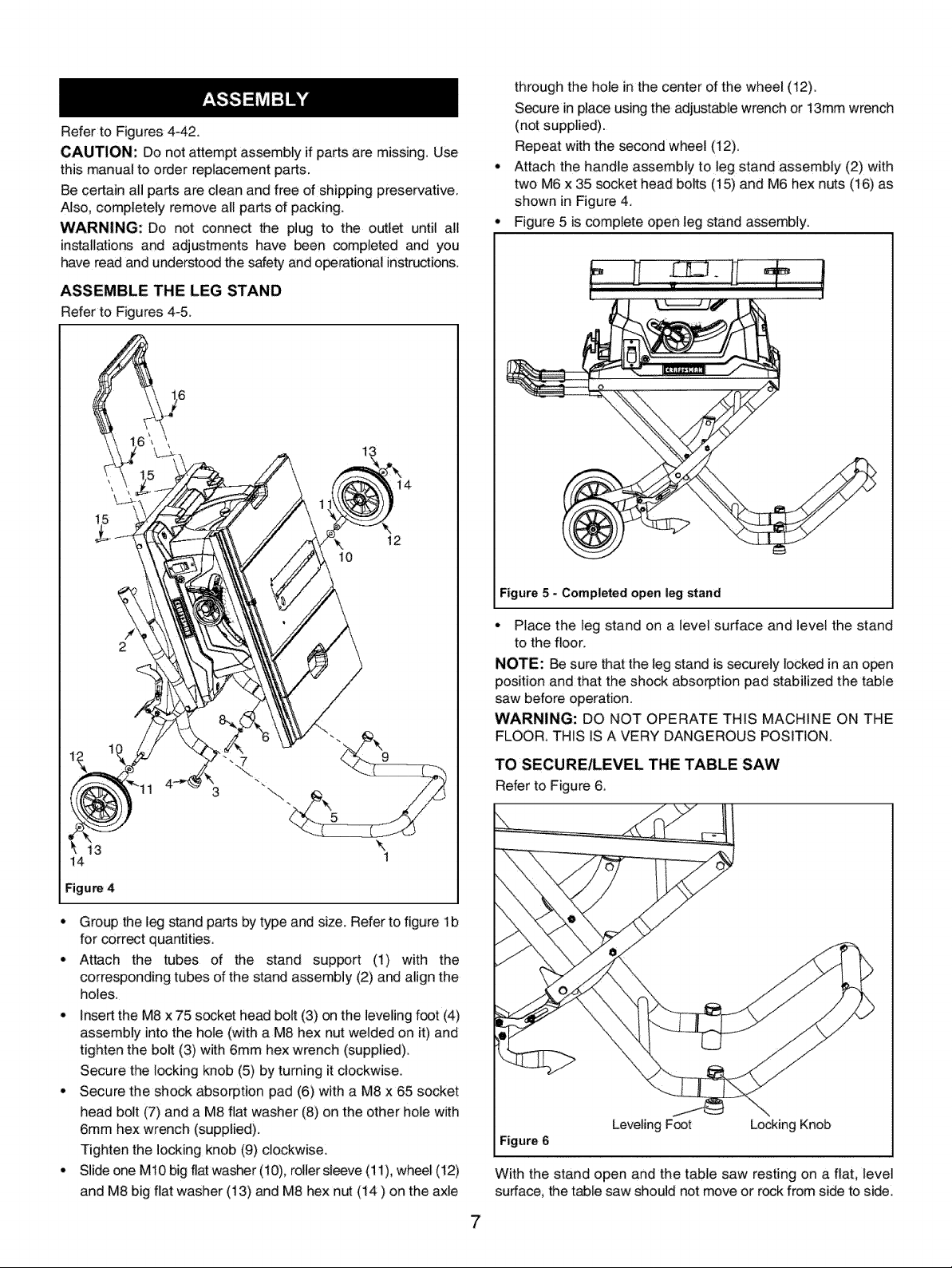
ASSEMBLE THE LEG STAND
Refer to Figures4-5_
12
10
through the hole inthe center of the wheel (12).
Secure in place using the adjustable wrench or 13mm wrench
(not supplied).
Repeat with the second wheel (12).
Attach the handle assembly to leg stand assembly (2) with
two M6 x 35 socket head bolts (15) and M6 hex nuts (16) as
shown in Figure 4.
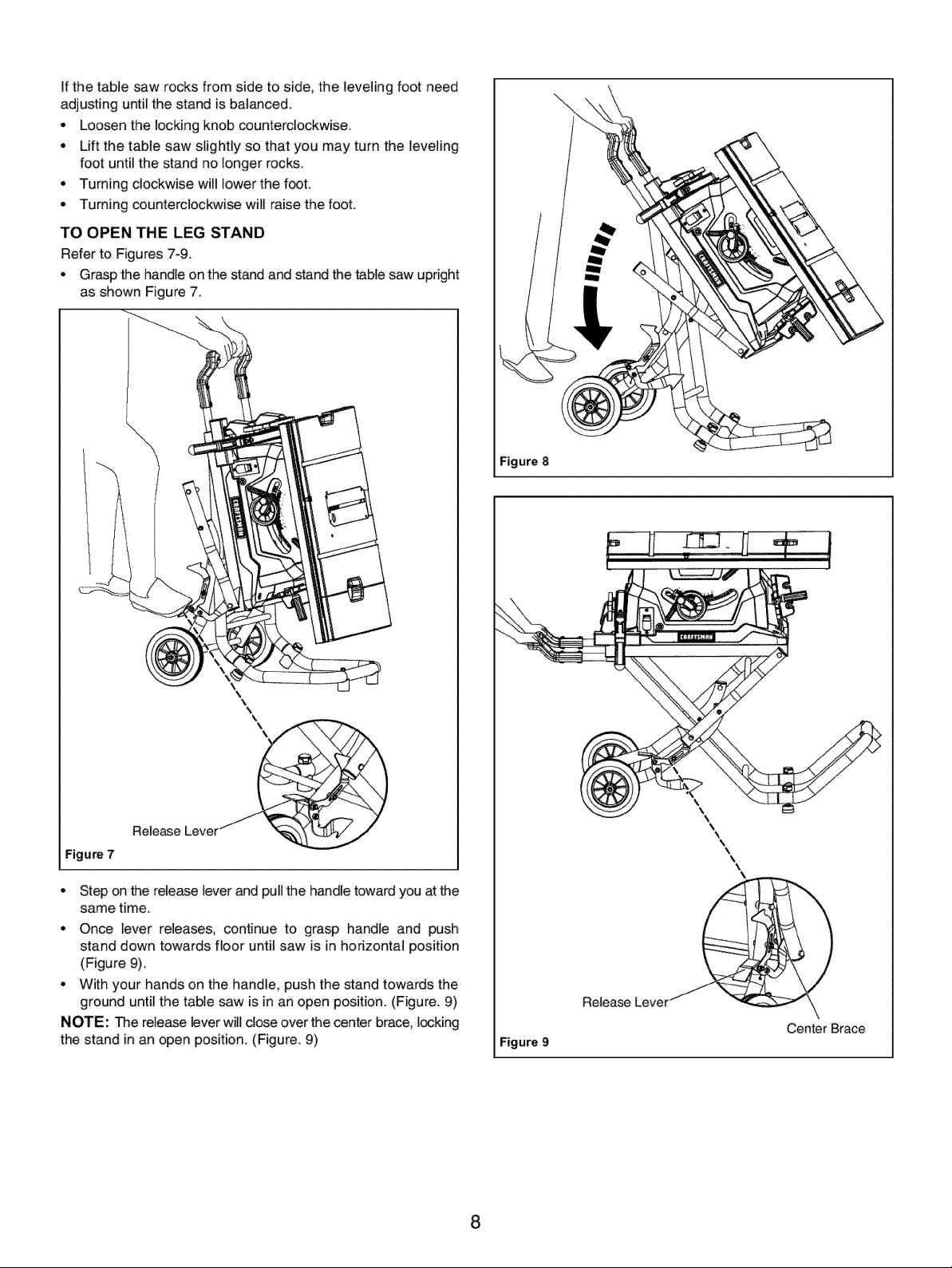
Figure 5 is complete open leg stand assembly:
....+ !
' l
14
Figure 4
• Group the leg stand parts by type and size. Refer to figure lb
for corr_t quantities.
• Attach the tubes of the stand support (1) with the
corresponding tubes of the stand assembly (2) and align the
holes.
• insertthe M8 x 75 socket head bolt (3) on the leveling foot (4)
assembly into the hole (with a M8 hex nut welded on it) and
tighten the bolt (3) with 6mm hex wrench (supplied).
Secure the locking knob (5) by turning it clockwise.
° Secure the shock absorption pad (6) with a M8 x 65 socket
head bolt (7) and a M8 flat washer (8) on the other hole with
6ram hex wrench (supplied).
Tighten the locking knob (9) clockwise.
• Slide one M10 big flat washer (10), roller sleeve (11), wheel (12)
and M8 big flat washer (13) and M8 hex nut (14) on the axle
Figure 5 _ Completed open leg stand
° Place the leg stand on a level surface and level the stand
to the floor.
NOTE: Be sure _at the leg stand is securely locked in an open
position and that the shock absorption pad stabilized the table
saw before operation.
WARNING: DO NOT OPERATE THIS MACHINE ON THE
FLOOR, THiS IS A VERY DANGEROUS POSITION.
TO SECURE/LEVEL THE TABLE SAW
Refer to Figure 6,
Leveling Foot Locking Knob
Figure 6
With the stand open and the table saw resting on a flat, level
surface, the table saw should not move or rock from side to side.
Page 8
Ifthetablesawrocksfromsidetoside,thelevelingfootneed
adjustinguntilthestandisbalanced.
° Loosenthelockingknobcounterclockwise.
° Liftthetablesawslightlysothatyoumayturntheleveling
footuntilthestandnolongerrocks.
• Turningclockwisewilllowerthefoot.
• Turningcounterclockwisewillraisethefoot.
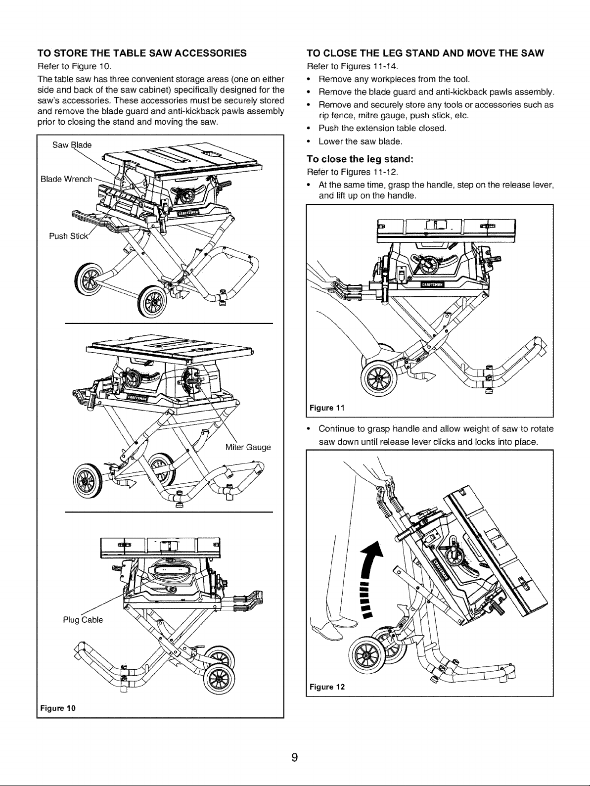
TOOPENTHELEGSTAND
RefertoFigures7-9.
° Graspthehandleonthestandandstandthetablesawupright
asshownFigure7.
\
Figure 8
Release
Figure 7
° Step on the release lever and pull the handle toward you at the
same time.
• Once lever releases, continue to grasp handle and push
stand down towards floor until saw is in horizontal position
(Figure 9).
° With your hands on the handle, push the stand towards the
ground until the table saw is in an open position. (Figure. 9)
NOTE: The release lever will close over the center brace, locking
the stand in an open position (Figure. 9)
8
Figure 9
Release Lever_
\
\
\
\
\
\
\
\
\
Center Brace
Page 9
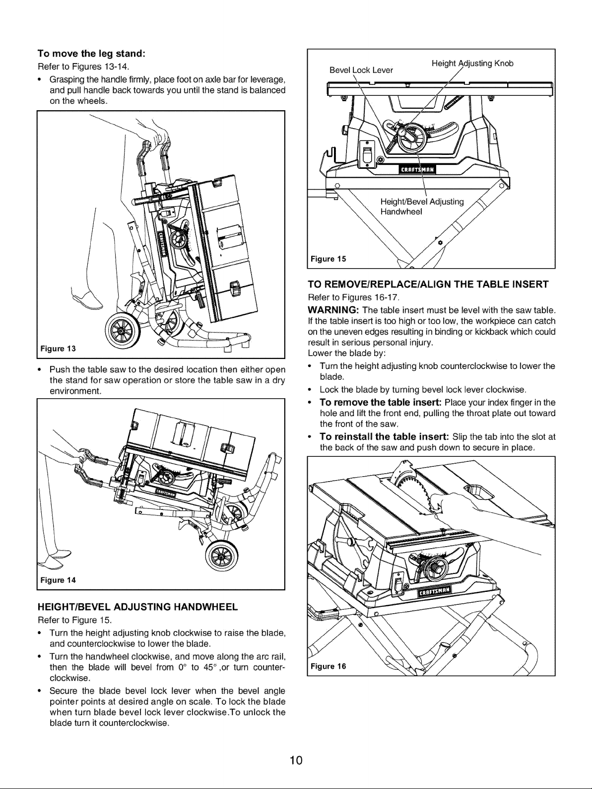
TO STORE THE TABLE SAW ACCESSORIES
Refer to Figure 10.
The table saw has three convenient storage areas (one on either
side and back d the saw cabinet) specifically designed for the
saw's accessories. These accessories must be securely stored
and remove the blade guard and anti-kickback pawls assembly
prior to closing the stand and moving the saw
Push
TO CLOSE THE LEG STAND AND MOVE THE SAW
Refer to Figures 11_14.
• Remove any workpieces from the tool.
• Remove the blade guard and anti-kickback pawls assembly.
• Remove and securely store any tools or accessories such as
rip fence, mitre gauge, push stick, etc.
• Push the extension table closed.
• Lower the saw blade:
To close the leg stand:
Refer to Figures 11_12.
• At the same time, grasp the handle, step on the release lever,
and lift up on the handle.
Plug Cable
Miter Gauge
Figure11
• Continue to grasp handle and allow ,weight of saw to rotate
saw down until release lever clicks and locks into place.
--...
Figure 12
Figure !0
9
Page 10
To move the leg stand:
Refer to Figures 13q 4.
• Grasping the handle firmly, place foot on axle bar for leverage,
and pull handle back towards you until the stand is balanced
on the wheels.
Figure 13
• Push the table saw to the desired location then either open
the stand for saw operation or store the table saw in a dry
environment.
BevelLock Lever
Figure 15
Height / Knob
TO REMOVE/REPLACE/ALIGN THE TABLE INSERT
Refer to Figures 16q7.
WARNING: The table insert must be level with the saw table.
If the table inseA is too high or too low, the work,piece can catch
on the uneven edges resulting in binding or kickback which could
result in serious personal injury.
Lower the blade by:
. "rum the height adjusting knob counterc!ockwise to lower the
blade_
• Lock the blade by turning bevel lock lever clockwise.
• To remove the table insert: Place your index finger in the
hole and lift the front end, pulling the throat plate out toward
the front of the saw;
• To reinstall the table insert: Slip the tab into the slot at
the back of the saw and push down to secure in place,
Figure 14
HEIGHT/BEVEL ADJUSTING HANDWHEEL
Refer to Figure 15.
• Turn the height adjusting l,_qobclockwise to raise the blade,
and counterclockwise to lower the blade.
• Turn the handwheel c]_kwise, and move along the arc rail,
then the blade will bevel from 0° to 45° ,or turn counter*
clockwise.
• Secure the blade bevel I_k _ever when the bevel angle
pointer points at desired angle on scale_ To lock the blade
when turn blade bevel lock lever clockwise.To unlock the
blade turn itcounterclockwise.
Figure 16
10
Page 11
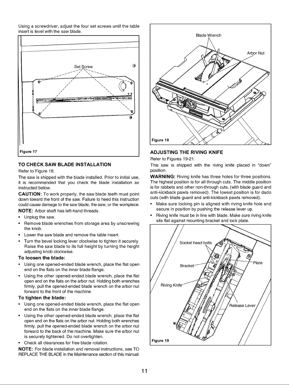
Using a screwdriver, adjust the four set screws until the table
insert is level with the saw blade.
Set Screw
@
Blade Wrench
Arbor Nut
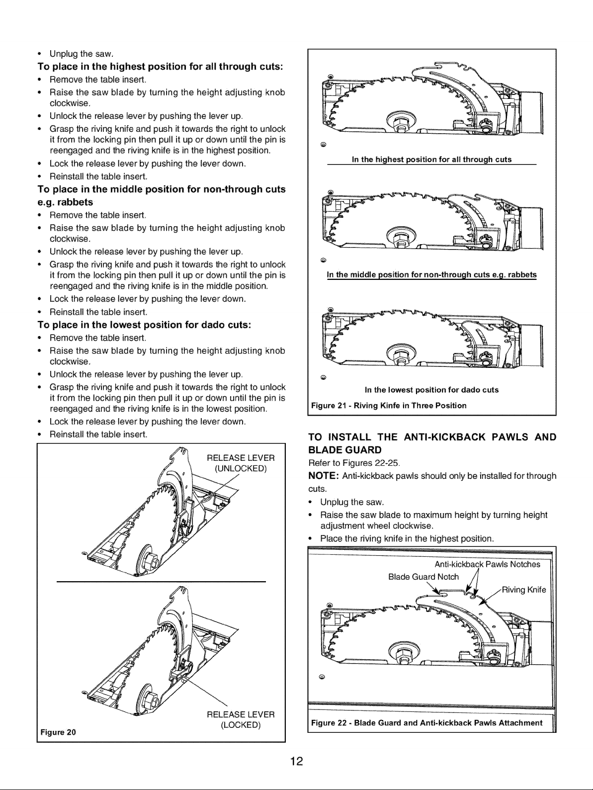
Figure 18
:igure 17
TO CHECK SAW BLADE INSTALLATION
Refer to Figure 18.
The saw is shipped with the blade installed. Prior to initial use.
it is recommended that you check the blade installation as
instructed below.
CAUTION: To work properly, the saw blade teeth must point
down toward the front of the saw. Failureto heed this instruction
could cause damage to the saw blade, the saw, orthe workpiece.
NOTE: Arbor shaft has left-hand threads.
* Unplug the saw.
° Remove blade wrenches from storage area by unscrewing
the knob.
° Lower the saw blade and remove the table insert.
° Turn the bevel locking lever clockwise to tighten it securely,
Raise the saw blade to its full height by turning the height
adjusting knob clockwise.
To loosen the blade:
, Using one opened-ended blade wrench, place the flat open
end on the flats on the inner blade flange.
, Using the other opened-ended blade wrench, place the flat
open end on the flats on the arbor nut. Holding both wrenches
firmly, pullthe opened-ended blade wrench on the arbor nut
forward to the front of the machine.
To tighten the blade:
° Using one opened-ended blade wrench, place the flat open
end on the flats on the inner blade flange.
° Using the other opened-ended blade wrench, place the flat
open end on the flats on the arbor nut. Holding both wrenches
firmly, pullthe opened-ended blade wrench on the arbor nut
forward to the back of the machine. Make sure the arbor nut
is securely tightened. Do not overtighten.
, Check all clearances for free blade rotation.
NOTE: For blade installation and removal instructions, see TO
REPLACE THE BLADE in the Maintenance section of this manual.
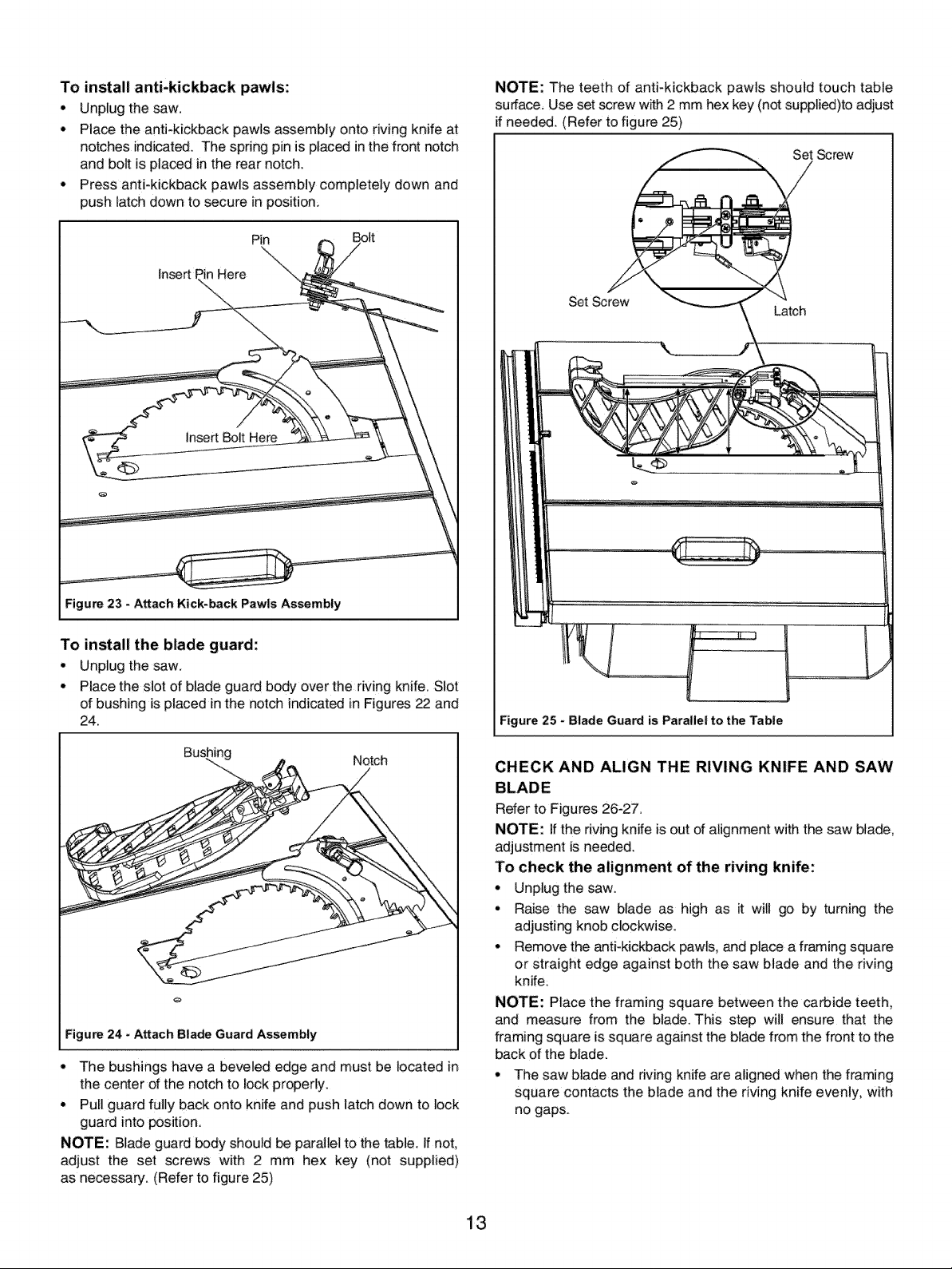
ADJUSTING THE RIVING KNIFE
Refer to Figures 19-21.
This saw is shipped with the riving knife placed in "down"
position.
WARNING: Riving knife has three holes for three positions.
The highest position is for all through cuts. The middle position
is for rabbets and other non-through cuts, (with blade guard and
anti-kickback pawls removed). The lowest position is for dado
cuts (with blade guard and anti-kickback pawls removed).
• Make sure locking pin is aligned with riving knife hole and
secure in position by pushing the release lever up.
° Riving knife must be in line with blade. Make sure riving knife
sits flat against mounting bracket and lock plate.
Socket head bolts
Figure 19
11
Page 12
• Unplug the saw.
To place in the highest position for all through cuts:
• Remove the table insert
• Raise the saw blade by turning the height adjusting knob
clockwise.
• Unlock the release lever by pushing the lever up.
• Grasp the riving knife and push it towards the right to unlock
it from the locking pin then pull it up or down until the pin is
reengaged and the riving knife is in the highest position.
• Lock the release lever by pushing the lever down,
• Reinstall the table insert,
To place in the middle position for non-through cuts
e.g. rabbets
• Remove the table insert.
• Raise the saw blade by turning the height adjusting knob
clockwise.
° Unlockthe release lever by pushing the lever up.
• Grasp the riving knife and push ittowards the right to unlock
it from the locking pin then pull it up or down until the pin is
reengaged and the riving knife is in the middle position
• Lock the release lever by pushing the lever down.
° Reinstall the table insert.
To place in the lowest position for dado cuts:
° Remove the table insert.
• Raise the saw blade by turning the height adjusting knob
clockwise,
° Unlock the release lever by pushing the lever up.
• Grasp the riving knife and push it towards the right to unlock
it from the locking pin then pull it up or down until the pin is
reengaged and the riving knife is in the lowest position.
° Lock the release lever by pushing the lever down
• Reinstall the table insert,
RELEASE LEVER
(UNLOCKED)
@
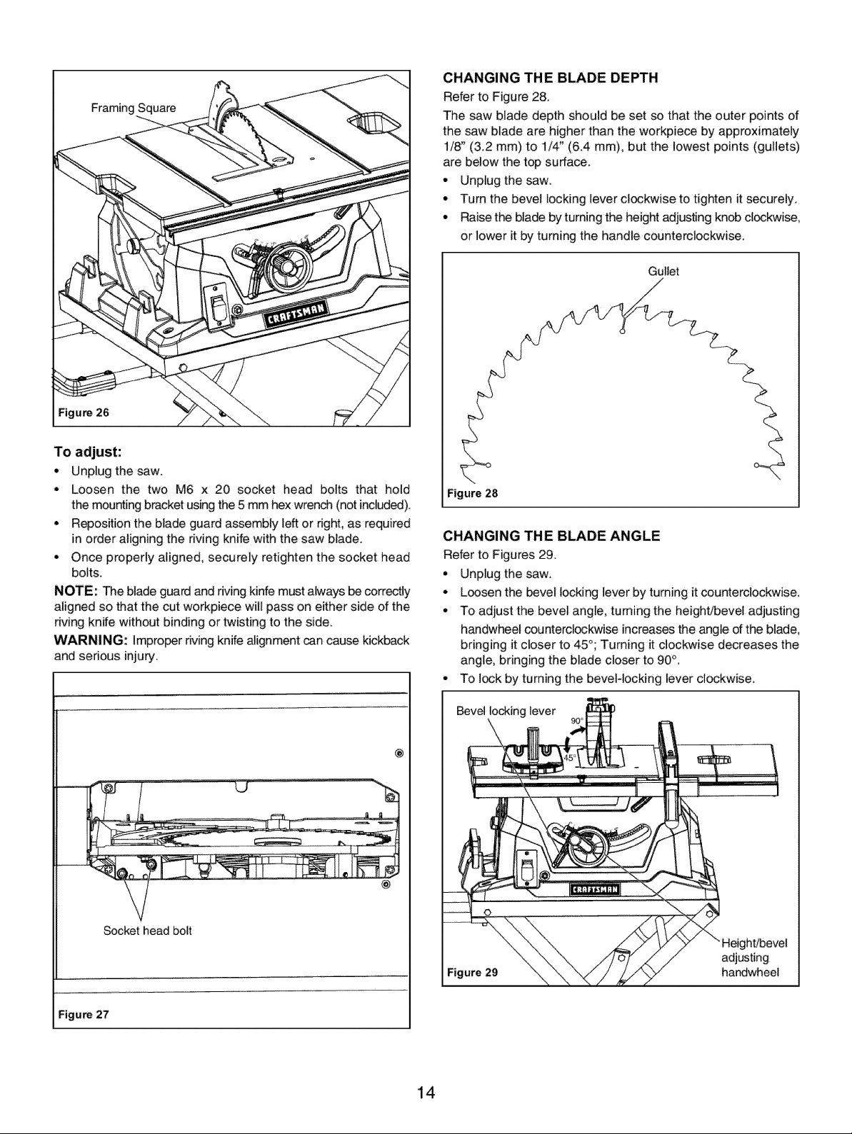
In the highest position for all through cuts
@
In the middle position for non4hrough cuts e,g, rabbets
In the lowest position for dado cuts
Figure 21 - Riving Kinfe in Three Position
TO INSTALL THE ANTI-KICKBACK PAWLS AND
BLADE GUARD
Refer to Figures 22-25,
NOTE: Anti-kickback pawls should only be installed for through
Cuts
• Unplug the saw.
• Raise the saw blade to maximum height by turning height
adjustment wheel clockwise.
° Place the riving knife in the highest position:
Figure 20
RELEASE LEVER
(LOCKED)
Anti-kickback Pawls Notches
Blade Guard Notch //
'/J Riving Knife
@
Figure 22 - Blade Guard and Anti.kickback Pawls Attachment
12
Page 13
To install anti-kickback pawls:
• Unplug the saw.
• Place the anti-kickback pawls assembly onto rMng knife at
notches indicated° The spring pin is placed in the front notch
and bolt is placed in the rear notch.
• Press anti-kickback pawls assembly completely down and
push latch down to secure in position;
Pin Bolt
Insert I Here
insert Bolt Here
NOTE: The teeth of anti-kickback pawls should touch table
surface, Use set screw with 2 mm hex key (not supplied)to adjust
if needed. (Refer to figure 25)
Set Screw
Set Screw
Latch
Figure 23 - Attach Kick-back Pawls Assembly
To install the blade guard:
• Unplug the saw.
• Place the slot of blade guard body over the rMng knife. Slot
of bushing isplaced in the notch indicated in Figures 22 and
24.
I Bushing Notch I
;igure 24 - Attach Blade Guard Assembly
• The bushings have a beveled edge and must be located in
the center of the notch to lock properly.
• Pull guard fully back onto knife and push latch down to lock
guard into position
NOTE: Blade guard body should be parallel to the _ble. If not,
adjust the set screws with 2 mm hex key (not supplied)
as necessary. (Refer to figure 25)
F
Figure 25 - Blade Guard isParallel to the Table
CHECK AND ALIGN THE RIVING KNIFE AND SAW
BLADE
Rder to Figures 26-27.
NOTE: If the riving knife is out of alignment with the saw blade,
adjustment is needed.
To check the alignment of the riving knife:
• Unplug the saw.
• Raise the saw blade as high as it will go by turning the
adjusting knob clockwise.
• Remove the anti-kickback pawls, and place a framing square
or straight edge against both the saw blade and the riving
knife.
NOTE: Place the framing square between the carbide teeth,
and measure from the blade. This step will ensure that the
framing square is square against the blade from the front to the
back of the blade.
• The saw blade and riving knife are aligned when the framing
square contacts the blade and the riving knife evenly, with
no gaps.
13
Page 14
Framing Square
To adjust:
• Unplug the saw.
• Loosen the two M6 x 20 socket head bolts that hold
the mounting bracket using the 5 mm hex wrench (not i_luded).
• Reposition the blade guard assembly left or right, as required
in order aligning the riving knife with the saw blade.
• Once properly aligned, securely retighten the socket head
bolts.
NOTE: The blade guard and riving kinfe must always be correctly
aligned so that the cut workpiece will pass on either side of the
riving knife without binding or twisting to the side.
WARNING: Improper riving knife alignment _n cause kickback
and sedous injury.
CHANGING THE BLADE DEPTH
Refer to Figure 28.
The saw blade depth should be set so that the outer points of
the saw blade are higher than the workpiece by approximately
1/8" (3.2 mm) to 1/4" (6.4 mm), but the lowest points (gullets)
are below the top surface.
• Unplug the saw.
o Turn the bevel locking lever clockwise to tighten it securely.
• Raise the blade by turning the height adjusting knob clockwise,
or lower it by turning the handle counterclockwise.
Gullet
Figure 28
CHANGING THE BLADE ANGLE
Refer to Figures 29.
° Unplug the saw.
• Loosen the bevel locking lever by turning it counterclockwise.
° To adjust the bevel angle, tuming the height/bevel adjusting
handwheel counterclockwise increases the angle of the blade_
bringing it closer to 45_; Turning it clockwise decreases the
angle, bringing the blade closer to 90°,
• To lock by tuming the beveldocking lever clockwise.
Socket head bolt
ure 27
Bevel locking lever
@
adjusting
Figure29 handwheel
14
Page 15

ADJUSTING THE BEVEL STOPS
Refer to Figures 30-32.
This saw has positive stops that will quickly position the saw
blade at 90° or 45 ° to the table.
The angle settings of the saw have been set at the factory and,
unless damaged in shipping, should not require setting during
assembly. After extensive use, it may need to be checked.
Set the 45 ° stop in the same way. The set screw for the 45°
stop is located in the right of table insert.
Triangle square
90° Set Screw
45° Set Screw
/
Figure 30
Make adjustments only if necessary.
• Unplug the saw.
° Raise the blade to the maximum height by turning the high
adjusting knob clockwise.
° Using a square, set the blade to exactly 90_.
° Ifthe blade stops bevelling before it gets to 90°, loosen the
set screw (located in the left of the table insert) with the
3 mm hex wrench (not included), and then adjust it to 90°.
° With the blade set at 90°, slowly turn the 90°*stop set screw
until you fee! resistance. Bevel the blade away from 90 ° a
little, and then back to the stop.
° Re-measure the angle, and repeat the stop adjustment as
necessary until the blade stops at 90°.
Figure 32
ADJUSTING THE BEVEL INDICATOR
Refer to Figures 33.
If the bevel indicator is not at 0° when the saw blade is at 90 °
adjust the indicator by loosening the cross-screw with a Phillips
screwdriver (not included) and setting it to 0° on the bevel scale
Retighten the screw.
NOTE: Make a trial cut on a scrap piece of wood before making
critical cuts. Measure for exactness.
CAUTION: To prevent personal injury:
° Always disconnect the plug from the power source when
making any adjustments.
• This adjustment must be correct_ or kickback could result in
a serious injury and inability to make accurate cuts.
Bevel indicator
Figure 31
15
Page 16

CHECKING THE ALIGNMENT OF THE RIP FENCE TO
THE BLADE
Refer to Figure 34.
• Unplug the saw.
° Remove the blade guard assembly,
• Raise the locking lever to allow the rip fence to be moved.
° Place the framing square beside the blade, and move the rip
fence up to the square. Note the measurement on the
rip scale.
° Move the fence back, and rotate the framing square 180° to
check the other side.
• If the two measurements are not the same, loosen the two
M6 x 16 socket head bolts on the fence using a 5 mm hex
key (not included), and then align it.
° Retighten the two socket head bolts.
• Make two or three test cuts using scrap wood. If the cuts are
not true, repeat the process.
Saw blade
Socket head bolt
Figure 34
Square
Rip fence
Rip fence
Figure 35
USING THE RIP FENCE
Refer to Figure 36.
° Unplug the saw.
° Place the rear lip d the ripfence on the rear of the saw table
and push it slightly toward the back of the unit.
• Lower the front end of the rip fence onto the guide surfaces
on top of the front rail.
° With the rip fence flat on the saw table, push the fence
towards the front rail to align the fence to the saw table.
° Push the locking lever down to align and secure the fence.
Check for a smooth gliding action, tf adjustments are needed,
see the previous section "Checking the alignment of the rip
fence to the blade".
• Make two or three test cuts using scrap wood. If the cuts are
not true, repeat the process.
NOTE: The rip fence must be secure when the locking lever
is engaged. To increase the grip of the rip fence on the rear lip
of the table, tighten the clamp screw on the rear of the dp fence
by turn it clockwise
SE_iNG THE RIP FENCE SCALE INDICATOR TO THE
BLADE
Refer to Figure 35.
Use the indicator on the rip fence to position the fence along
the scale on the front rail,
Begin with the blade at 90 ° angle (straight up),
° Unplug the saw.
° Loosen the rip fence by lifting the locking lever.
° Place the rip fence on the saw table so that it lightly touches
the right side of the saw Made. Lock the dp fence in place.
° Loosen the cross-screw using a Phillips screwdriver (not
included) and adjust the indicator so that the red line is I_ated
over the "0" line on the front rail of the right-hand rip scale.
Retighten the screw.
NOTE: The blade guard assembly must be removed to perform
this adjustment. Reinstall the blade guard assembly when the
adjustment is complete
Clamp
Figure 36
16
Page 17

USING THE MITER GAUGE
Refer to Figures 37-38.
The miter gauge provides greater accuracy in angled cuts. For
very close tolerances, test cuts are recommended. There are
two miter gauge channels, one on either side of the blade. When
making a 90° crosscut, use either miter gauge channel. When
making a bevel crosscut (the blade tilted in relation to the table),
the miter gauge should be located in the slot on the right so that
the blade is tilted away from the miter gauge and away from
your hands. The miter gauge can be turned 60 ° to the right or
leftsPositive stops at 0°_ 22.5° and 45° can be located with
rotating the gauge. Face of miter gauge has two holes for
purpose of attaching auxiliary facing.
* Slide the miter gauge in the miter gauge slot.
° Loosen the locking knob.
* With the miter gauge in the miter gauge slot, rotate the gauge
until the desired angle is reached on the scale.
° Retighten the locking knob.
USING THE SLIDING EXTENSION TABLE
Refer to Figure 39.
Increase the length of the saw table by using the extension table.
° Set the rip fence to 14_'(355.6 mm) on the right rail.
• Push the extension-table locking lever to nght to unlock the
lever.
° Slide the extension table to the desired width,
NOTE: Use the scale on the left rait when a specific width is
desired.
° Once the extension table is set to the desired width, re/ock
the lever by pulling the lever to left.
lever
Extension table
To lock
Locking knob
Figure 37
To adjust miter gauge base:
The miter gauge base should swivel smoothly on the bar a_er
the locking knob is loosened. If adjustment is required:
° Loosen the locking knob
• if the base is too loose, turn the cross-screw in a clockwise
direction, if the base is too tight, turn the cross-screw in a
counterclockwise direction.
Cross-screw
!
Bar
lever
Extension table
To
Figure 38
Figure 39
17
Page 18

TO ATTACH DUST EXTRACTION PORT TO SAW
Refer to Figure 40.
Attach the dust extraction port to the pipe located on the back
of saw body as shown in illustration belowing.
Dust extraction port
Pipe
:igure 40
TO USE DUST EXTRACTION PORT
WARNING: To prevent fire hazard, clean and remove sawdust
from under the saw frequently.
To prevent sawdust buildup inside the saw housing, for best
result, attach a vacumm hose (not included) to the dust extraction
port. DO NOT operate the saw with hose in place unless the
vacuum is turned on.
If the saw is operated without a vacuum attached, some of the
dust will be blown out the dust extraction port. After extended
use, the saw's dust collection system may become clogged.
Properly G!
Grounding
3-Prong
Figure 41 - 3-Prong Receptacle
• Do not remove or alter grounding prong in any manner, tn
the event of a malfunction or breakdown, grounding provides
a path d least resistance for electrical shock.
WARNING: Do not permit fingers to touch the terminals
d plug when installing or removing from outlet.
• Plug must be plugged into matching outlet that is properly
installed and grounded in accordance with all local codes and
ordinances, Do not modify plug provided, If it will not fit in
outlet, have proper outlet installed by' a qualified electrician.
° inspect toot cords periodically and if damaged, have them
repaired by an authodzed service facility.
• Green (or green and yellow) conductor in cord is the grounding
wire. tf repair or replacement of the electdc cord or plug is
necessary, do not connect the green (or green and yellow)
wire to a live terminal:
• Where a 2-prong wall receptacle is encountered, it must be
replaced with a properly grounded 3-prong receptacle installed
in accordance with National Electric Code and local codes
and ordinances:
WARNING: This work should be performed by a qualified
electrician.
A temporary 3-prong to 2-prong grounding adapter (see Figure
42) is available for connecting plugs to a two pole outlet if it is
properly grounded.
Sure This is
Ads Connected to A
3-Prong Plug Known Ground
Refer to Figures 41-42:
GROUNDING INSTRUCTIONS
WARNING: Improper connection of equipment grounding
conductor can result in the risk of electrical shock. Equipment
should be grounded while in use to protect operator from
electrica! shock.
• Check with a qualified electrician if grounding instructions
are not understood or if in doubt as to whether the tool
is properly grounded.
• This too! is equipped with an approved 3-conductor cord
rated at 300V and a 3-prong grounding type plug (see Figure
41) for your protection against shock hazards.
• Grounding plug should be plugged directly into a properly
installed and grounded 3- prong grounding4ype receptacle,
as shown (Figure 41).
2-Prong Receptacle
Figure 42 - 2-Prong Receptacle with Adapter
* Do not use a 3-prong to 2-prong grounding adapter unless
permitted by local and national codes and ordinances.
° (A 3-prong to 2-prong grounding adapter is not permitted in
Canada.) Where permitted_ the rigid green tab or terminal
on the side of the adapter must be securely connected to a
permanent electrical ground such as a properly g rounded
water pipe, a properly grounded outlet box or a properly
grounded wire system.
o Many cover plate screws, water pipes and outlet boxes are
not properly grounded. To ensure proper ground, grounding
means must be tested by a qualified electrician
EXTENSION CORDS
° The use of any extension cord will cause some drop in voltage
and loss of power.
• Wires of the extension cord must be of sufficient size to carry
the current and maintain adequate voltage.
° Use the table to determine the minimum wure size (A_W.G.)
18
Page 19

extensioncord:
• Useonly3-wireextensioncordshaving3-pronggrounding
typeplugsand3-polereceptacleswhichacceptthe tool plug.
• If the extension cord is worn, cut, or damaged in any way,
replace it immediately.
Extension Cord Length (120V Operation)
Wire Size A.W.G,
Up to 25 ft........................................ 14
Up to 50 ft........................................ 12
NOTE:Using extension cords over 50ft. long is not
recommended.
Extension Cord Length (240V Operation)
Wire Size A.W.G.
Up to 50 ft........................................ 18
50to 100 ft....................................... 16
100to 200 ft...................................... 14
200 tO 300 ft ..................................... 12
NOTE:Using extension cords over 300ft. long is not
recommended.
ELECTRICAL CONNECTIONS
WARNING: All ele_rical connections must be performed by a
qualified electridan. Make sure tool is off and disconnected from
power source before inspecting any wiring.
The saw is prewired for use on a 120 volti 60Hz power supply.
The power lines are inserted directly onto the switch
The green ground line must remain securely fastened to
the frame to properly protect against electrical shock.
° Remove the key to prevent unauthorized use.
Refer to Figures 43a_57.
The Craftsman 10" Model Number 14258 table saw offers precise
cutting performance for all woods up to 3_4" (8 cm) thick. The
saw is designed for the DIYers and is ruggedly constructed for
continuous service. The 10" Table Saw is recommended for use
with a 10" blade.
The saw features a right extension table with ripping capacity
of 24!._" (62.2 cm). Saw body has on board storage for push stick.,
miter gauge, rip fence and saw blades and blade wrenches. Saw
is equipped with a riving knife and a clear acrylic blade guard
with anti-kickback feature. Cabinet is constructed of plastic and
included a dust extraction port.
Rip Fence Assembly features a preci_on ripfence that is designed
for simple and one-hand maneuverability. Front rail is calibrated
in inches.
Foldable Leg Stand with wheels features an easy transport and
storage.
SPECIFICATIONS
Capacity with 10" Blade:
Depth of cut at 90% ........................ 3W' (8 cm)
Maximum tilt angle of arbor (left) ..................... 45°
Depth of cut at 45_ . ....................... 2%_"(5.5 cm)
Max. cut right of blade with rip fence ......... 24VJ' (62.2 cm)
Saw Dimensions:
Cabinet depth .......................... 11%2" (29 cm)
Cabinet width .......................... 20_4" (52.7 cm)
Cabinet length ......................... 25%_2"(63.9 cm)
Main table size ................. 24 x 2!'/IJ' (61 x 53.5 cm)
Extension table ............. 56'3AJ'x 21/_÷" (15.2 x 53.5 cm)
Saw Blade:
Blade max. capacity: ..................... 10" (25.4 cm)
Blade arbor .............................. :%" (1.59 cm)
Dado blade max. capacity: ................... _" (1.27 cm)
Saw Constructions:
Cabinet .................................... Plastic
Table .................................. Cast aluminum
Rip fence ........................... Aluminum extrusion
Drive system ................................. By gear
Mitre gauge ................... Cast aluminium with T-rod
Blade guard ............... Acrylic with anti-kickback pawls
Motor .............................. 120 V, 15 A, 60 Hz
No load speed ............................... 4500RPM
Net weight with leg stand ............... 82.5 Ibs (37.5 kg)
Shipping weight ......................... 94.6 Ibs (43 kg)
WARNING: Disconnect power before attempting any of the
following procedures. Be certain switch is in OFF position and
the key is removed. Saw blade must not be moving. Saw blade
will rotate freely after motor is turned off. Allow blade to come
to a complete stop before attempting any of the following
procedures.
WARNING: The operation of any power tool can result in
foreign objects being thrown into the eyes, which can result in
severe eye damage. Always wear safety goggles corn plying
with United States ANSI Z87.1 before commencing power tool
operation.
WARNING: Do not allow familiarity with a toot to make you
careless. Remember that afraction of a second of carelessness
is sufficient to cause serious injury.
WARNING: Do not use any attachments or accessories that
are not recommended by the manufacturer of this tool. The use
of attachments or accessories that are not recommended can
result in serious personal injury.
WARNING: Although many of the illustrations in this Operator's
Manual are shown with the blade guard removed for clarity, do
not operate the saw with-out the blade guard unless specifically
instructed to do so.
WARNING: The table saw must be mounted to a firm. supporting,
waist high surface_ such as a workbench or leg stand. Many
illustrations in this Operator's Manual are shown with the saw
unmounted for clarity.
APPLICATIONS
You can use this tool for the purposes listed below:
• Straightqine cutting operations, such as crosscutting, ripping,
mitering, beveling, and compound cutting.
• Dado or molding cuts with optional accessories.
• Cabinet making and woodworking
NOTE: This table saw is designed to cut wood and wood
composition products only.
19
Page 20

BASIC OPERATION OF THE TABLE SAW
The 3-pronged plug must be plugged into a matching outlet that
is properly installed and grounded in compliance ,with all local
codes and ordinances, improper connection of the equipment
can result in electdc shock. Check with an electrician or service
technician ff you are unsure about proper grounding. Do not alter
the plug. if it will not fit into the outlet, have the proper outlet
installed by a qualified electrician,
CAUSES OF KICKBACK
Kickback can occur when the blade stalls or binds, causing the
workpie-ce to be kicked back toward the operator with great force
and speed, ff your hands are near the saw blade, they may be
jerked loose from the workpiece and come into contact with the
blade. Obviously, kickback can cause serious injury, and it is
well worth using precautions to avoid the dsks.
Kickback can be caused by' any action that pinches the blade in
the wood, such as the following:
• Making a cut w_h incorrect blade depth.
• Sawing into knots or nails in the work piece.
• Twisting the wood while making a cut.
• Failing to suppo_ the workpiece.
• Forcing a cut.
• Cutting warped or wet lumber.
• Using the wrong blade for the type of cut.
• Not following correct operating procedures.
• Misusing the saw.
• Failing to use the anti-kickback pawls.
• Cutting with a dull, gummed-up, or improperly set blade.
AVOIDING KICKBACK
• Always use the correct blade depth setting. The top of the
blade teeth should clear the workpiece by VJ' (3.2 ram) to
_/_"(6.4 mm).
° Inspect the workpiece for knots or nails before beginning a
cut. Knock out any loose knots with a hammer. Never saw
into a loose knot or nail.
° Always use the rip fence when rip cu_ing and the miter gauge
when crosscutting. This helps to prevent twisting the wood
in the cut.
° Always use clean, sharp, and properly set blades. Never make
cuts with dull blades.
• To avoid pinching the blade, support the work properly before
beginning a cut.
• When making a cut, use steady, even pressure. Never force
cuts.
• Do not cut wet or warped lumber.
• Always hold the workpiece firmly with both hands or with push
sticks. Keep your body in a balanced position to be ready to
resist kickback should it occur. Never stand directly in line
with the blade.
° Use the right type of blade forthe cut being made.
PUSH STICK
Refer to Figure 43a-43b.
• Push sticks are devices used for safely pushing a workpiece
through the blade instead d using your hands. They can be
made from scrap wood in various sizes and shapes to
be used in a sp_ific project. The stick must be narrower than
the workpiece, witha 90° notch in one end and shaped for a
grip on the other end.
Figure 43a - Push Stick
• Use good quality' plywood
or solid wood
° Use X/' or _" material
° Push stick MUST be thinner
than the width of material
being cut
Drill Hole
For Hanging
o
Prevent Hand
From Slipping
/
/
/
/
i
/
/
/
Cut Here To
'/_" Wood
Cut Here To
/ 90 °
Figure 43b * Push Stick Construction
Push _" Wood
PUSH BLOCK
Refer to Figure 44.
• A push block has a handle fastened with recessed screws
from the underside. Be sure the screws are recessed. Use
it on non-through cuts.
CAUTION: Be sure the screws in a push block are recessed
to avoid damaging the saw or workpiece.
How to make a push block
Make a push block using pieces of %" (9,5 mm) plywood and
%" (19 mm) hardwood. Position the handle in the center of the
plywood, and fasten them together with glue and wood screws
Use a push stick whenever the fence is 2" (5 cm) or more from
the blade, Use a push block when the operation is too narrow
to allow for the use of a push stick For proper use, see "BEVEL
RIPPING". Either the push stick or block should be used in place
of the useCs hand to guide the material between the fence and
blade. When using a push stick or a push block, the trailing end
of the board must be square. A push stick or block against an
uneven end could slip off or push the work away from the fence,
20
Page 21

Dardwood
To use the featherboard:
° Unplug the saw.
• Completely lower the saw blade.
• Position the rip fence to the desired adjustment for the cut to
be performed, and lock the rip fence.
° Place the wo¢_piece against the fence and over the saw blade
area.
• Adjust the featherboard to apply resistance to the workpiece
just forward of the blade.
° Attach a C-clamp (not supplied) to secure the featherboard
to the edge of the saw table.
Plywood
Figure 44 - Push Block
HOW TO MAKE AND USE THE FEATHERBOARD
Refer to Figures 45-46.
A featherboard is a device used to help control the workpiece
by guiding it securely against the table or fence. Featherboards
are especially useful when ripping small workpieces and for
completing non-through cuts. The end is angled with a number
of shod kerfs to give a friction hold on the workpiece and locked
in place on the t_le with a C-clamp. Test to ensure it can resist
kickback: Place the featherboard against the uncut portion of
the wo#,_.pieceto avoid kickbad_ that could cause serious personal
injury.
To make the featherboard:
The featherboard is an excellent project for the saw,
• Sel_ a solid pi_e of lumber approximately _" (19 ram) thick,
3 5/_"(9 cm) wide and 18" (45 cm) long.
• Mark. the Center of the width on one end of the stock.
• Miter one-half of the width to 30°, and miter the other half of
the same end to 45° (see "MITER CUTS" for more information).
• Mark the board from the point at 6" (15 cm), 8" (20 cm), 10"
(25 cm), and 12" (30 cm). Drill a %, (9.5 ram) hole at the 8"
(20 cm), 10" (25 cm), and 12" (30 cm) marks.
• Set the rip fence to allow an approximately V4"(6.5 mm)
"finger" to be cut in the stock. Feed the stock only to the maA
previously made at 6" (15 cm).
• Turn the saw OFF, and allow the blade to completely stop
rotating before removing the stock.
• Reset the rip fence, and cut spaced rips into the workpiece
to allow approximately W' (6.5 ram) fingers with _4"(3 ram)
spaces between the fingers.
Figure 45 - Fatherboard
Push Block
Workpiece
C-clamp
Push Stick
Featherboard
Figure 46 - Blade Guard and Anti-kickback Pawls Attachment
WARNING: Do not locate the featherboard to the rear of the
workpiece. If positionedimproperly, kickback can result from the
featherboard pinching the workpiece and binding the blade in the
saw kerr. Failure to heed this warning can result in serious
personal injury.
TYPES OF CUTS
Refer to Figure 47.
There are six basic cuts: 1) the cross cut, 2) the rip cut, 3) the
miter cut, 4) the bevel cross cut, 5) the bevel rip cut, and, 6) the
compound (bevel) miter cuL All other cuts are combinations of
these basic six. Operating procedures for making each kind of
cut are given later in this section.
WARNING: Always make sure the blade guard and anti-kickback
pawls are in place and working properly when making these cuts
to avoid possible injury.
Cross cuts are straight 90° cuts made across the grain of the
work,piece. The wood is fed into the cut at a 90_ angle to
the blade, and the blade is vertical
Rip cuts are made with the grain of the wood. To avoid kickback
while making a rip cut, make sure one side of the wood rides
firmly against the rip fence,
Miter cuts are made with the wood at any angle to the blade
other than 90°. The blade is vertical. Miter cuts tend to "creep"
during cutting. This can be controlled by holding the workpiece
securely against the miter gauge.
WARNING: Always use a push stick with small pieces of wood,
21
Page 22

and also to finish the cut when ripping a long narrow piece of
wood, to prevent your hands from getting close to the blade.
Bevel cuts are made with an angled blade. Bevel cross cuts are
across the wood grain, and bevel rip cuts are with the grain. The
rip fence must always be on the right side of the blade for bevel
rip cuts.
Compound (or bevel) miter cuts are made with an angled blade
on wood that is angled to the blade. Be thoroughly familiar with
making cross cuts, rip cuts, bevel cuts, and miter cuts before
trying a compound miter cut.
CROSSCUT
RIP CUT
CUTTING TIPS
Dado and rabbet cuts are non-through cuts which can be either
rip cuts or cross cuts. Carefully read and understand all sections
of this operator's manual before attempting any operation,
WARNING: Do not use blades rated less than the speed of
this tool. Failure to heed this warning could result in personal
injury,
° The kerf (the cut made by the blade in the wood) will be wider
than the blade to avoid overheating or binding, Make allowance
for the kerr when measuring wood,
° Make sure the kerf is made on the waste side of the measuring
line,
• Cut the wood with the finish side up,
° Knock out any loose knots with a hammer before making
the cut.
- Always provide proper support for the wood as itcomes out
of the saw,
SWITCH ASSEMBLY
Refer to Figure 48.
This saw is equipped with a switch assembly that has a built-in
locking feature, This feature is intended to prevent unauthorized
and possibly hazardous use by children and others.
To turn your saw ON:
With the switch key inserted into the switch, lift the switch to turn
it ON.
To turn your saw OFF:
Press the switch down to turn it OFF.
To lock your saw:
Press the switch down. Remove the switch key from the switch,
and store it in a safe, secure location.
Figure 47
MITER CUT
BEVEL CROSS CUT
BEVEL RiP CUT
COMPOUND (BEVEL) MITER CUT
/
Switch On
Switch in Locked Position
Figure 48
WARNING: Always remove the switch key when the tool is not
in use, and keep the switch key in a safe place. In the event of
a power failure, turn the switch OFF and remove the key: This
action will prevent the tool from accidentally starting when the
power returns.
WARNING: ALWAYS make sure that your workpiece is not in
contact with the blade before operating the switch to start the
Switch Off
ch Key
Page 23

tool.Failuretoheedthiswarningmaycausethework.pieceto
bekickedbacktowardtheoperator,andmayresultinserious
personalinjury:
Toreducetheriskofaccidentalstarting,alwaysmakesurethe
switchisintheOFFpositionbeforepluggingthetoolintothe
powersource.
OVERLOAD PROTECTION
The saw is equipped with the overload switch to prevent the saw
from overload damage. The saw will stop if the machine was with
overloaded cutting or low voltage. Turn the switch to the OFF
position and allow the motor to cool down for at least five minutes.
And press the overload switch button to resume the overload
switch. After the motor has cooled down, turn the switch to the
ON position; The saw should now start.
SAW BLADE
For maximum performance, it is recommended that you use the
10% %" arbor holes and 40-tooth blade provided with your saw.
Additional blade styles of the same high quality are available for
specific operations such as ripping. Your local dealer can provide
you with complete information.
WARNING: Do not use blades rated less than the speed of this
tool, Failure to heed this warning could result in personal injury,
WARNING: To prevent possible electrical hazards, have a
qualified electrician check the line if you are not certain that it is
properly wired
MAKING CUTS
The blade provided with the saw is a high-quality combination
blade suitable for ripping and cross cut operations.
WARNING: Do not use blades rated less than the speed of this
tool. Failure to heed this warning could result in personal injury.
Use the miter gauge when making cross, miter, bevel, and
compound miter cuts. To secure the angle, lock the miter gauge
in place by twisting the lock knob clockwise. Always tighten the
lock knob securely in place before use.
NOTE: It is recommended that you place the piece to be saved
on the left side of the blade and that you make a test cut on scrap
wood first.
MAKING A CROSS CUT
Refer to Figure 49.
It is recommended you make test cuts on scrap wood.
WARNING: Using the rip fence as a cutoff gauge when cross
cu_ing will result in kickback which can cause serious personal
injury
WARNING: Make sure the blade guard assembly is installed
and working properly to avoid serious personal injury.
• Remove the rip fence by lifting the locking lever.
• Set the blade to the correct depth for the workpiece.
• Set the miter gauge to 0° and tighten the lock knob.
• Place a support (the same height as saw table) behind the
saw for the cut work.
• Make sure the wood is clear of the blade before turning on
the saw.
t To turn the saw ON, lift the switch.
t To turn saw OFF, press the switch down.
NOTE: To prevent unauthorized use, remove the switch key as
shown in figure 48.
• Let the blade build up to full speed before moving the
workpiece into the blade.
° Hold the workpiece firmly with both hands and feed the
workpiece into the blade.
NOTE: The hand closest to the blade should be placed on the
miter gauge lock knob and the hand farthest from the blade
should be placed on the workpiece.
- When the cut is made, turn the saw off. Wait for the blade to
come to a complete stop before removing any part of
the workpiece.
Figure 49 - CROSS CUT
MAKING A RIP CUT
Refer to Figures 50.
It is recommended you make test cuts on scrap wood.
WARNING: Make sure the blade guard assembly is installed
and working properly to avoid serious personal injury.
• Remove the miter gauge by sliding it out of the miter gauge
groove.
• Set the blade to the correct depth for the workpiece.
° Set the blade to 0°
• Position the dp fence the desired distance from the blade for
the cut and securely lock the handle.
• Place a support (the same height as the saw table) behind
the table saw for the cut work.
° Make sure the wood is clear of the blade before turning on
the table saw.
° Use a push block or push stick to move the wood through
the cut past the blade. Never push a small piece of wood
into the blade with your hand. Always use a push stick.
The use of push blocks, push sticks, and featherboards are
necessary when making non-through cuts.
• Stand to the side of the wood as it contacts the blade
to reduce the chance of inju_ should kickback occur. Never
stand directly in the line of cut,
• Make sure the wood is clear of the blade before turning on
the table saw.
° Let the blade build up to full speed before feeding the
workpiece into the blade.
° When the cut is made, turn the saw off. Wait for the blade to
come to a complete stop before removing any part of
the workpiece.
23
Page 24

I I
Workpiece
Figure 50 - RIP CUT
MAKING A MITER CUT
Refer to Figure 51
It is recommended you make test cuts on scrap wood
WARNING: Make sure the blade guard assembly is installed
and working properly to avoid serious personal injury.
• Remove the rip fence by lifting the locking lever.
° Set the blade to the correct depth for the workpiece.
° Set the miter gauge to desired angle and tighten the
lock knob.
- Place a support (the same height as saw table) behind the
saw for the cut work.
- Make sure the wood is clear of the blade before turning on
the saw
• Let the blade build up to full speed before moving the
workpiece into the blade.
° Hold the workpiece firmly with both hands and feed the
workpiece into the blade.
NOTE: The hand closest to the blade should be placed on the
miter gauge lock knob and the hand farthest from the blade
should be placed on the workpiece.
- When the cut is made. turn the saw off. Wait for the blade to
come to a complete stop before removing any part of
the workpiece.
CAUTION: The miter gauge cannot be used in the left miter
gauge groove when bevel cutting due to blade guard interference.
Only use the miter gauge in the right miter gauge groove when
bevel cutting.
Figure 51 - MITER CUT
MAKING A BEVEL CROSS CUT
Refer to Figure 52.
It is recommended that you place the piece to be saved on the
left side of the blade and that you make a test cut on scrap wood.
WARNING: Make sure the blade guard assembly is installed
and working properly to avoid serious personal injury.
• Remove the rip fence by lifting the locking lever.
° Unlock the bevel locking lever and move height/beve!
adjusting handwheel until bevel indicator is at desired angle.
° Re]ock the bevel locking lever.
° Set the blade to the correct depth for the workpiece.
• Set miter gauge to 0° and tighten the lock knob.
° Place a support (the same height as saw table) behind
the saw for the cut work.
° Make sure the wood is clear of the blade before turning
on the saw.
° Let the saw blade build up to full speed before moving
the miter gauge and the workpiece into the blade.
° Hold the workpiece firmly with both hands and feed the
workpiece into the blade.
NOTE: The hand closest to the blade should be placed on the
miter gauge lock knob and the hand farthest from the blade
should be placed on the work,piece.
° When the c_ is made, turn the saw off, Wait for the blade to
come to a complete stop before removing any part of
the workpiece.
24
Page 25

Figure 52 - BEVEL CROSS CUT
MAKING A BEVEL RIP CUT
Refer to Figure 53.
It is recommended you make test cuts on scrap wood.
WARNING: The rip fence must be on the right side of the blade
to avoid trapping the wood and causing kickback. Placement
of the rip fence to the left of the blade will result in kickback and
the risk of serious personal injury.
WARNING: Make sure the blade guard assembly is installed
and working properly to avoid serious personal injury.
° Unlock the bevel locking lever and move height!bevel
adjusting handwheel until bevel indicator is at desired angle.
• Relock the bevel locking lever.
• Set the blade to the correct depth for the workpiece.
• Position the rip fence the desired distance from the right side
of the blade and lock down the lever.
• If ripping a larger piece, place a support the same height as
the table surface behind the saw for the cut work.
• Make sure the wood is clear of the blade before turning on
the saw,
° Position the workpiece fiat on the table with the edge flush
against the rip fence, Let the blade build up to full speed
before feeding the workpiece into the blade.
° Using a push stick and/or push blocks, slowly feed the
workpiece toward the blade. Stand slightly to the side of the
wood as it contacts the blade to reduce the chance of injury
should kickback occur.
• Once the blade has made contact with the workpiece, use
the hand closest to the rip fence to guide it. Make sure the
edge of the workpiece remains in solid contact with both the
rip fence and the surface of the table. If ripping a narrow piece,
use a push stick to move the piece through the cut and past
the blade
° When the cut is made turn the saw off. Wai! for the blade
to come to a complete stop before removing any part of the
workpiece,
° After the blade has stopped completely, remove the cutoff
stock.
° Grasp the wo£Kpiecefrom the lead end (the end fed into the
blade first) and carefully remove it from the saw table.
Workpie_
Figure 53 - BEVEL RIP CUT
MAKING A COMPOUND (BEVEL) MITER CUT
Refer to Figure 54.
It is recommended that you place the piece to be saved on the
left side of the blade and that you make a test ct._on scrap wood.
WARNING: Make sure the blade guard assembly is installed
and working properly to avoid serious personal injury,
° Remove the rip fence by lifting the locking lever.
° Unlock the bevel locking lever and move height/bevel
adjusting handwheel until bevel indicator is at desired angle.
• Push the bevel locking lever toward the table to relock it.
° Set the blade to the correct depth for the workpiece.
• Set the miter gauge to desired angle and tighten the lock
knob.
° Make sure the wood is clear of the blade before turning ON
the saw.
° Hold the workpiece firmly with both hands and feed the
workpiece into the blade.
NOTE: The hand closest to the blade should be placed on the
miter gauge lock knob and the hand farthest from the blade
should be placed on the workpiece.
- Advance the workpiece and the miter gauge toward the blade.
Keep the workpiece flush against the miter gauge. Stand
slightly to the side of the wood as it contacts the blade
to reduce the chance of injury' should kickback occur.
° When the cut is made, turn the saw OFF. Wait for the blade
to come to a complete stop before removing any part of the
workpiece.
° After the blade has stopped completely, remove the cutoff
stock.
25
Page 26

Workpiece
Figure 54 _ COMPOUND (BEVEL) MITER CUT
MAKING A LARGE PANEL CUT
Refer to Figure 55.
Make sure the saw is properly secured to a work surface
to avoid tipping from the weight of a large panel.
WARNING: Make sure the blade guard assembly is installed
and working properly to avoid serious personal injury.
• Place a support the same height as the top of the saw table
behind the saw for the cut work. Add supports to the sides as
needed.
• Depending on the shape of the panel, use the rip fence or
miter gauge. !f the panel istoo large to use either the rip fence
or the miter gauge, it is too large for this saw.
WARNING: Never make freehand cuts (cuts without the miter
gauge or rip fence), Such a cut increases the risk of kickback
and can result in serious injury.
Make sure the wood is clear of the blade before turning
on the saw.
• Let the blade build up to full speed before moving the
workpiece into the blade.
° Hold the workpiece firmly and feed the workpiece into the
blade.
° When the cut is made, turn the saw off. Wait for the blade
to come to a complete stop before removing any part of the
workpiece.
° After the blade has stopped completely, remove the cutoff
stock.
Workpiece
Figure 55 - LARGE PANEL CUT
MAKING A NON-THROUGH CUT
Refer to Figure 56.
Non4hrough cuts can be made with the grain (ripping) or across
the grain (cross cut). The use of a non-through cut is essential
to cutting grooves, rabbets, and dadoes. DO NOT perform bevel
non-through cuts on this machine.
NOTE: This is the only type of cut that is made without the blade
guard assembly installed. Make sure the blade guard assembly
_sreinstalled upon completion of this type of cut.
Read the appropriate section which describes the type of cut in
addition to this section on non-through or dado cuts. For
example, if your non-through cut is a straight cross cut, read and
understand the section on straight cross cuts before proceeding.
WARNING: When making a non4hrough cut, the cutter is
covered by the workpiece during most of the cut. Be alert to the
exposed cutter at the start and finish of every cut to avoid the
risk of serious personal injury.
WARNING: Never feed wood with your hands when making
any non-through cut such as rabbets. To avoid personal injury,
always use push blocks, push sticks, and featherboards.
- Unplug the saw.
° Remove the blade guard assembly and anti-kickback pawls
assembly.
* Unlock the release lever.
° Set the riving knife in the middle position.
* Relock the release lever.
° Set the blade to 0°,
* Set the blade to the correct depth for the workpiece.
° Plug the saw into the power source.
* Turn the saw ON.
° Feed the workpiece into the blade.
NOTE: Always use push blocks, push sticks, and featherboards
when making non4hrough cuts to avoid the risk of serious injury.
° When the cut is made, turn the saw off. Wait for the blade
to come to a complete stop before removing any part of the
work_piece.
Once all non4hrough cuts are complete:
26
Page 27

• Unplugthesaw.
° Raisethebladeandreinstallthebladeguardassemblyand
anti*kickbackpawlsassembly.
Workpiece
° After the cut is made, turn the saw off. Wait for the blade to
come to a complete stop before removing the workpiece,
NOTE: When cutting with a dado blade, use a dust collection
system to prevent heavy dust loads from piling up under the saw
and on the fan intake on the motor. Clean these areas often,
WARNING: Always put all spacers in proper location when
changing back to saw blade. Failure to do so may result in
possible injury and damage to the tool.
Workpiece
Figure 56 - NON-THROUGH CUT
DADO CUTTING
Refer to Figure 57.
The dado table insert included is required for this procedure.
Blades and dado sets must not be rated lower than the speed
of this tool. This saw is designed for use with an 6" (152 cm)
stack dado up to ;z,,,(12.7 mm) wide. Do not use an adjustable
dado with this saw.
WARNING: This saw cannot be used to make a bevel dado
cut,
- Unplug the saw.
° Remove the blade guard anti-kickback pawls and table insert.
° Remove the arbor nut blade outer flange saw blade.
° Mount the dado blade, using the appropriate blade and
chippers for the desired width of cut.
- Reinstall the outer flange and the arbor nut.
NOTE: Make sure the arbor nut is fully engaged and the arbor
extends past a securely tightened arbor nut.
° Place the riving knife in the lowest position.
° Place the release lever in the locked position.
° Install the dado table insert, rotate the blade by hand to make
sure it turns freely, and then lower the blade.
° Plug the saw into the power source and turn iton_
• Position the workpiece flat on the table, with the edge flush
against the rip fence or miter gauge.
° use a push block or push stick to move the wood through the
cut past the blade. Never push a small piece of wood into
the blade using your hand. Always use a push stick and
featherboard.
WARNING: Always use push blocks, push sticks, or featherboards
when making dado cuts to avoid the risk of serious injury.
Figure 57 - DADO CUT
WARNING: Do not attempt under any circumstan_s, to service,
repair, dismantle, or disassemble any mechanical or electrical
components without physically disconnecting all power sources.
GENERAL MAINTENANCE
Avoid using solvents when cleaning plastic parts. Most plastics
are susceptible to damage from various types of commercial
solvents. Use clean cloths to remove dirt, dust, oil, grease, etc.
Do not allow brake fluid, gasoline, petroleum-based products,
penetrating oils, etc., to come into contact with plastic parts.
Chemicals can damage, weaken or destroy plastic, which may
result in serious personal in-jurj.
• Periodically check all clamps, nuts, bolts, and screws for
tightness and condition. Make sure that the throat plate is in
good condition and in the proper position.
• Check the blade guard assembly.
• Clean blades using a gum and pitch remover.
• To maintain the table surfaces and rails, periodically apply
paste wax to them and buff them to ensure smooth functioning.
To prevent work from slipping during cutting operations, DO
NOT wax the working face of the miter gauge.
° Protect the saw blade by cleaning sawdust out from under
the saw table and between the blade teeth. Use a resin
27
Page 28

solvent on the blade teeth. Do not use gasoline!
• Clean plastic parts only with a soft damp cloth. Do not use
any aerosol or petroleum solvents.
LUBRICATION
° This saw's motor bearings have been packed at the factory
with proper lubrication.
° Clean screw threads and nuts using a solvent recommended
for gum and pitch removal.
• Lubricate screw threads, nuts, and bearing points (including
those on the blade guard assembly and the miter gauge).
SERVICE
° Replace worn parts as needed, if power cords are worn, cut,
or damaged in any way, have them replaced immediately.
° Make sure teeth of antFkickback pawls are always sharp.
° Sharpen dull teeth using a few light strokes of a smooth cut
flat file.
TO REPLACE THE BLADE
Refer to Figures 58-59.
When you need replace the saw blade, please follow the
procedure as be!owing:
• Unplug the saw.
• Unscrew red knob on side of saw to remove blade wrenches
from storage area.
° Remove blade guard assembly and pawl assembly.
° Turn height adjustment hand wheel counterclockwise to drop
the saw blade to lowest position, and remove the table insert.
° Turn hand wheel clockwise to raise blade to maximum height.
• Using one opened-ended blade wrench, place the flat open
end on the flats on the inner blade flange.
° Using the other opened-ended blade wrench, place the flat
open end on the flats on the arbor nut. Holding both wrenches
firmly, pull the opened-ended blade wrench on the arbor nut
forward to the front of the machine.
WARNING: Be extremely careful when loosening arbor nut.
Keep firm grasp on both wrenches. Do not allow hands to slip
and contact blade.
• Raise the riving knife locking lever to upright position.
° Remove arbor nut, outer blade flange and saw blade.
• Place one new blade on arbor. Make sure saw blade teeth
point down at the front side of saw t_le. Place outer flange
and nut on arbor and use blade wrenches to tighten nut
securely.
° Push the riving knife locking lever back to locked position,
° Lower the saw blade to lowest position and replace
table insert.
° Replace blade guard assembly and pawl assembly,
NOTE: Blade may be stored on the side of the saw in the same
storage area provided for the blade wrenches.
Blade Wrench
Arbor Nut
Figure 58
Inner Blade Flange
Outer Blade Flange
Saw Blade
BRUSH REPLACEMENT
Refer to Figure 63.
° Unplug the saw.
° Lower blade completely and bevel to 45% Lock the blade.
° Turn saw upside down.
° Remove brush caps with a screwdriver.
NOTE: Brush assembly is spring load and will pop out when
brush cap is removed.
° Remove brush assemblies and check for wear.
° Replace both brushes when either has less than VJ' length
of carbon remaining. Do not replace one side without
replacing the other.
° Reassemble using new b_sh assemblies by reversing the
steps listed above. Make sure curvature of brush matches
curvature of motor and that brush moves freely in brush tube.
° Tighten all brush caps securely. Do not overtighten.
28
Page 29

Figure 60
B_sh Cap
Brush Assembly
29
Page 30

Sewice Record
Craftsman 10" Table Saw with Foldable Stand
I DATE MAINTENANCE PERFORMED REPLACEMENT PARTS REQUIRED J
3O
Page 31

SYMPTOM CORRECTIVE ACTION
Saw will not start 1.
POSSIBLE CAUSE(S)
1. Overload tripped
Allow motor to cool and reset by
pushing reset switch
2, Saw is not plugged in
3. Fuse blown or circuit breaker tripped
4, Cord is damaged
2.
Plug in saw
3,
Replace fuse or reset circuit breaker
4.
Have the cord replaced by a qualified
electrician
Does not make 45° and 90° rip cuts
1, Positive stop not adjusted correctly
1. Check blade with square and adjust
positive stop
2. Bevel angle pointer not set accurately
2. Check blade with square and adjust
to zero
3. Rip fence not be properly aligned
3, Align the rip fence with the mitre
gauge slot
Material pinched blade when ripping 1, 1,
Rip fence not aligned with blade
2, 2,
Warped wood, edge against fence is
Check and adjust rip fence
Select another piece of wood
not straight
Material binds on riving knife 1, 1.
Saw makes unsatisfactory cuts
Riving knife not aligned correctly with
blade
1.
Dull blade
2.
Blade mounted backwards
3.
Gum or pitch on blade
Check and align riving knife with
blade
1. Replace blade
2. Turn the blade around
3, Remove the blade and clean with
turpentine and coarse steel wool
Material kicked back from blade
4. Incorrect blade for work being done
5, Gum or pitch on blade causing erratic
feed
1, Rip fence out of adjustment
2. Riving knife not aligned with blade
3. Feeding stock without rip fence
4. Riving knife not in place
4. Change the blade
5. Clean table with turpentine and steel
WOOl
1. Align rip fence with miter gauge slot
2. Align riving knife with blade
& Instal] and use rip fence
4. Install and use rMng knife (with
guard)
5. Dull blade
6. The operator letting go of material
before it is past saw blade
7. 7,
Miter angle lock knob is not tight
Blade does not raise or tilt freely 1. 1.
Sawdust and dirt in elevation/tilting
5. Replace blade
6: Push material all the way past saw
blade before releasing work
Tighten knob
Brush or blow out loose dust and dirt
mechanisms
Blade does not come up to speed 1. 1. Replace with adequate size cord
Reset trips too easily 2. 2: Contact your electric company
Machine vibrates excessively 1. 1. Tighten all mounting hardware
Extension cord too light or too long
Low house voltage
The saw is not mounted securely to the
stand
Does not make accurate 45° and 90°
2. Stand on uneven floor
3. Stand is not balanced
4. Damaged saw blade
1. Miter gauge out of adjustment
2. Rep_sition on fiat level surfece
3. Adjust the leveling foot
4. Replace blade
1. Adjust miter gauge
31
Page 32

Repair Protection Agreements
Congratulations on making a smart purchase: Your new
Craftsman '_product is designed and manufactured for years
of dependable operation. But like all products_ it may require
repair from time to time. That,s when having a Repair Protection
Agreement can save you money' and aggravation.
Here's what the Repair Protection Agreement*
includes:
[] Expert service by our 10,000 professional repair specialists
[] Unlimited service and no charge for parts and labor on all
covered repairs
[] Product replacement up to $1500 if your covered product
can't be fixed
[] Discount of 25% from regular pdce of service and related
installed parts not covered by the agreement; also 25% off
regular pdce of preventive maintenance check.
[] Fast help by phone - we call it Rapid Resolution - phone
support from a Sears representative. Think of us as a "talking
owner's manual."
Once you purchase the Repair Protection Agreement, a simple
phone call is af! that it takes for you to schedule service.
You can call anytime day or night, or schedule a service
appointment online,
The Repair Protection Agreement is a risk-free purchase, if you
cancel for any reason during the product warranty period, we
will provide a full refund. Or, a prorated refund anytime after the
product warranty period expires, Purchase your Repair Protection
Agreement today!
Some limitations and exclusions apply. For prices and
additional information in the U.S.A. call 1-800-827-6655.
*Coverage in Canada varies on some items. For full details
call Sears Canada at 1-800-36%6665.
Sears Installation Service
For Sears professional insta!lation of home appliances, garage
door openers, water heaters, and other major home items, in
the U.S.A. or Canada call 1-888-3314569.
32
Page 33

Figure 61 - Replacement Parts Illustration for Rip Fence
C_0
Model 141.142580
Page 34

KEY
NO.
1
2
3
4
5
6
7
8
9
10
11
12
13
14
15
16
17
PART NO.
142580,001
142580002
142580.003
142580.004
142580.005
142580,006
142580007
142580.008
142580.009
142580,010
142580.011
142580.012
142580.013
142580014
142580,015
142580.016
142580.017
DESCRIPTION
Cross Recessed Countersunk Head Screw M4x8
Pressure Pad
Clamping Ring
Eccentric Clamp Lever
Forcing Spindle
Fixed Seat
Pointer
Flat Washer 4
Cross Recess Pan Head Screw M4xl0
Hexagon Socket Button Head Screws M6x12
Fence
Locking Thread Rod
Friction Pad
Flat Washer 6
Compression Spring
Locking plate
Hexagon lock nut M6
QTY.
4
2
2
1
1
1
1
1
1
2
1
1
1
3
1
1
1
34
Page 35

Model 141.142580
Figure 62 - Replacement Parts Illustration for Cabinet
!/7
\
4
5
26
\
2827 _ 24 _ 22
29
12
t4
15
2t
35
Page 36

KEY
NO.
1
2
3
4
5
6
7
8
9
10
11
12
13
14
15
16
17
18
19
20
21
22
23
24
25
26
27
28
29
PART NO.
142580,018
142580.019
142580.020
142580.021
142580.022
142580,023
14258&024
142580.025
142580.026
142580,027
142580°028
142580.029
142580.030
142580.031
142580,032
142580.033
142580,034
142580.035
142580.036
142580.037
142580.038
142580.039
142580.040
142580.041
142580.042
142580:043
142580.044
142580.045
142580.046
DESCRIPTION
Blade Knob
Blade Wrench
Blade
Lock Sleeve
Hex Nut M8
Hexagon Socket Cap Screws M8x35
Flat Washer 8
Hexagon Bolt M8x35
Saw Cabinet
Cross Trough Pan Head Self-drilling Screw ST4.2x12
Power Cord Storage
Sheath
Power Cord 14AWG
Line C_amp
Cross Trough Pan Head Self-drilling Screw ST4.2x16
Fastener
Big Flat Washer 5
Cross Recess Pan Head Screw M5x20
Protective Ring
Cross Trough Pan Head Self-drilling Screw ST2.9x9
Base Plate
Switch Box Cover
Junction Box
Switch Plate
Overload Protector 15A
Switch
Flat Washer 4
Cross Recess Pan Head Screw M4x12
Nut
QTY.
1
2
1
1
1
4
4
1
1
6
1
1
1
1
2
2
4
4
2
2
1
1
1
1
1
1
2
2
1
36
Page 37

Figure 63 - Replacement Parts Illustration for Rail
Model 141.142580
Page 38

KEY
NO.
1
2
3
4
5
6
7
8
9
10
11
12
13
14
15
16
17
18
19
20
21
22
23
24
25
26
27
28
29
3O
31
32
33
34
35
36
37
38
39
40
41
42
43
44
45
46
PART NO.
14258,_7
14258,048
14258.049
14258.050
14258,051
14258,052
1425&053
14258.054
14258.055
14258.056
14258.057
14258.058
14258.059
14258,060
14258.061
14258.062
14258,063
14258,064
1425&065
14258.066
1425&067
1425&068
14258.069
14258.070
1425&071
14258,072
14258.073
14258,074
14258,075
1425&076
14258.077
14258,078
1425&079
14258,080
14258,081
14258.082
14258,083
14258,084
14258.085
14258.086
14258,087
14258,088
14258.089
14258,090
1425&091
14258.092
DESCRIPTION
Cross Trough Pan Head Self-drilling Screw ST&5x13
End Cap (A)
Stop block (B)
Cross Trough Pan Head Self-drilling Screw ST3.5x10
Friction Pad A
Main Rail
Scale Label
Cross Recess Pan Head Screw M4
Hexagon Socket Cap Screws M6
Fdction Pad C
Spring Washer 4
Flat Washer 4
Pointer
Cross Recessed Countersunk Head _rew M5x8
End Cap (B)
Table Insert
Main Worktable
End Cap for Rear Rail (A)
End Cap for Rear Extension
Rear Rail
Base Plate
Hexagon Bolt M6xl 6
Spring Washer 6
Flat Washer 6
Stop Block (A)
End Cap for Rear Rail (B)
Knurl Screw
Hex Nut M8
Fixed Plate
Hexagon Socket Cap Screws M6x20
Longer Nut (A)
Cross Recess Pan Head Screw M5xt2
Spring Washer 5
Flat Washer 5
Retain Plate (B)
Spring Column Pin 3×20
Locking Rod Spring
Locking Rod
Big Flat Washer 8
Allen Flat End Set Screws M6x20
Longer Nut (B)
Locking Lever
Locking Block
Retain Plate (A)
Side Extension Table
Dado Insert
QTY.
2
1
1
2
1
1
1
2
1
2
1
1
1
4
1
1
1
1
2
1
1
4
4
5
5
1
1
3
2
4
1
6
6
6
2
2
1
1
1
2
1
1
2
t
1
1
38
Page 39

28
33
22
/ /
/
/
z
z
/
/
7 21
0
m
0
/
12 42
40
12
\
22
\,
\
\
\
\
m
_m
I,I.
o
|
39
Page 40

KEY
NO. PART NO,
1 142580.093
2 142580.094
3 142580.095
4 142580.096
5 142580.097
6 142580.098
7 142580.099
8 142580.100
9 142580.101
10 142580.102
11 142580.103
12 142580.104
13 142580.105
14 142580.106
15 142580.107
16 142580.I0f
17 142580.109
18 142580.110
19 142580.!11
20 142580,112
21 142580.113
22 142580.114
23 142580,!15
24 142580.116
25 142580.117
26 142580.118
27 142580,119
28 142580.120
29 142580.121
30 142580.020
31 142580.!22
32 142580.123
33 142580.124
DESCRIPTION QTY.
Cross Recess Pan Head Screw M5x20 4
Spring Washer 5 6
Flat Washer 5 6
Guide Post 2
Motor 1
Adjusting Seat 1
Spacer 2
Hexagon Lock Nut M5 2
Pressing Sleeve 1
Locating Pin 2
Flat Washer 6 8
Spring Washer 6 4
Hexagon Socket Cap Screw M6xl 6 2
Riving Knife Holder 1
RMng Knife 1
Pressing Plate 1
Compression Spring 1
Clamp Lever 1
Allen Flat End Set Screw M6x12 1
Bolt 1
Trunion 1
Cross Recess Pan Head Screw M4xl0 6
Adjusting Rod (A) 1
Flat Key 4x8 2
Retainer Ring 10 2
Bevel Gear 2
Dust Adaptor 1
Dust Port 1
Inner Flange 1
Blade 1
Outer Flange 1
Nut M16 1
Baffle Plate 1
KEY
NO. PART NO.
34 142580.125
35 142580.126
36 142580.127
37 142580.128
38 142580.129
39 142580.130
40 142580.131
41 142580.132
42 142580.133
43 142580.134
44 142580.135
45 142580.136
46 142580.137
47 142580,138
48 142580.139
49 142580.140
50 142580.141
51 142580.142
52 142580,143
53 142580.144
54 142580.145
55 142580.146
56 142580.147
57 142580.!48
58 142580.149
59 142580.150
60 142580.151
61 142580.152
62 142580.153
63 142580.154
DESCRIPTION QTY.
Small baffle 1
Flat Washer 4 5
Spring Washer 4 5
Big Flat Washer 5 1
Cross Recess Pan Head Screw M5x12 1
Hexagon Socket Cap Screw M5x20 2
Gliding Sheet 2
Fixed Seat (A) 2
Cross Recess Pan Head Screw M6x16 4
Lower Baffle 1
Adjustable Lever (B) 1
Fixed Seat (B) 1
Hexagon Bolt M6x 16 2
Strengthen Plate 1
Pointer 1
Rack (B) 1
Spacer 1
Spring 1
Threaded Rod 1
Hex Nut M5 3
Cross Recess Pan Head Screw M5x12 1
Cross Recessed Countersunk Head 2
Screw M5x16
Cross Recessed Countersunk Head 4
Screw M5×8
Locking Handle 1
Rotation Wheel 1
Cross Recess Pan Head Screw 1
M5x16
Handlebar 1
Rotation Knob 1
Bolt 1
End Cover 1
40
Page 41

Model 141.142580
Figure 65 - Replacement Parts Illustration for Stand
10
8
2
\
1¸1¸
9
3
t2
13
5
5
Oj.,.,
9
7
23
24
26
25
41
Page 42

KEY
NO.
1
2
3
4
5
6
7
8
9
10
11
12
13
14
15
16
17
18
19
20
21
22
23
24
25
26
27
28
29
3O
31
32
33
34
35
36
37
38
39
40
PART NO,
142580.155
142580.156
142580.157
142580,158
142580.159
142580.160
142580.161
142580,162
142580.163
142580.164
142580.165
142580,166
142580.167
142580.168
142580.169
142580,170
142580.171
142580.172
142580.173
142580 t74
142580.175
142580.176
142580.177
142580.178
142580.179
142580.180
142580.181
142580:182
142580.t83
142580.184
142580.185
142580.186
142580.187
142580.t88
142580.189
142580.190
142580.191
142580.t92
142580.193
142580.194
DESCRIPTION
Hexagon Bolt M8x70
End Cap
Stand Support (C)
Spacer (A)
Lock Nut M8
Hexagon Bolt M8x90
Hexagon Bolt M8x95
Rolling Sleeve
Spacer (C)
Hexagon Bolt M8x80
Stand Frame
Cross Recess Pan Head Screw M5x35
Upper Handle
Locknut M6
Support Bar
Hexagon Socket Cap Screws M6x35
Lower Handle
Nut M5
Cross Trough Pan Head Self-drilling Screw ST4.2x12
Stand Support (B)
Paddle (A)
Paddle (C)
Big Flat Washer 8
Bushing
Wheel Assembly
Big Flat Washer 10
Flat Washer 8
Button Spring
Spacer Bush
Hexagon Bolt M8x65
Hexagon Bolt M8x60
Hexagon Thin Nut M8
Shock Pad (A)
Hexagon Socket Cap Screw M8x75
Stand Support(A)
Knob
Foot
Stand Support (D)
Hexagon Socket Button Head M8x60
Nut M8
QTY.
3
8
1
5
13
2
2
1
2
1
1
4
1
2
2
2
1
4
4
1
1
1
3
2
2
2
5
1
1
1
3
1
1
1
1
2
3
1
2
3
42
Page 43

Model 141.142580
Figure 66 - Replacement Parts Illustration for Blade Guard
3
2
\
12
14
5
t6
5 3
17
14
!8
f
15
43
Page 44

KEY
NO.
1
2
3
4
5
6
7
8
9
10
11
12
13
14
15
16
17
18
19
20
21
22
23
24
25
26
27
28
29
3O
31
32
33
34
35
PART NO,
142580,195
142580.196
142580.197
142580,198
142580,199
142580,200
142580.201
142580.202
142580,203
142580,204
142580205
142580.206
142580.207
142580,208
142580.209
142580.210
142580,211
142580,212
142580,213
142580.214
142580.215
142580.216
142580.217
142580.218
142580_219
142580,220
142580.221
142580.222
142580.223
142580.224
142580.225
142580.226
142580.227
142580,228
142580229
DESCRIPTION
Left Blade Guard
Hexagon Bolt M6x58
Hexagon Lock Nut M6
Washer (C)
Flat Washer 6
Clamping Sleeve(A)
Sleeve
Mounting Plate
Cross Recessed Countersunk Head Screw M4xl0
Allen Flat End Set Screw M4x15
Supporting Seat
Gasket
Connecting Sha_ (A)
Spring Pin 4x12
Rotating Detent
Right Blade Guard
Split Washer
Anti kickback Pawl
Clamping Sleeve (B)
Torsional Spring
Holder
Cross Recess Pan Head Screw M3x12
Connecting Sha_ (B)
Locking Knob
Big Flat Washer 6
Miter Gauge
Pointer
Steel Ball
Spring
Allen Flat End Set Screw M6x12
Flat Washer 3
Cross Trough Pan Head Self'drilling Screw ST2.9x9
Fd_ion Pillar
Positioning Bolt
Guiding Bar
QTY.
1
1
3
3
2
2
2
1
2
2
1
2
1
2
2
1
1
2
2
1
1
1
1
1
1
1
1
1
1
1
2
2
3
1
1
44
Page 45

II:R
1
® Registered Trademark / TMTrademark of KCD IP, LLC in the United States, or Sears Brands, LLC in other countries
® Marca Registrada / Marca de Fabrica de KCD IP, LLC en Estados Unidos, o Sears Brands, LLC in otros paises
TM
 Loading...