

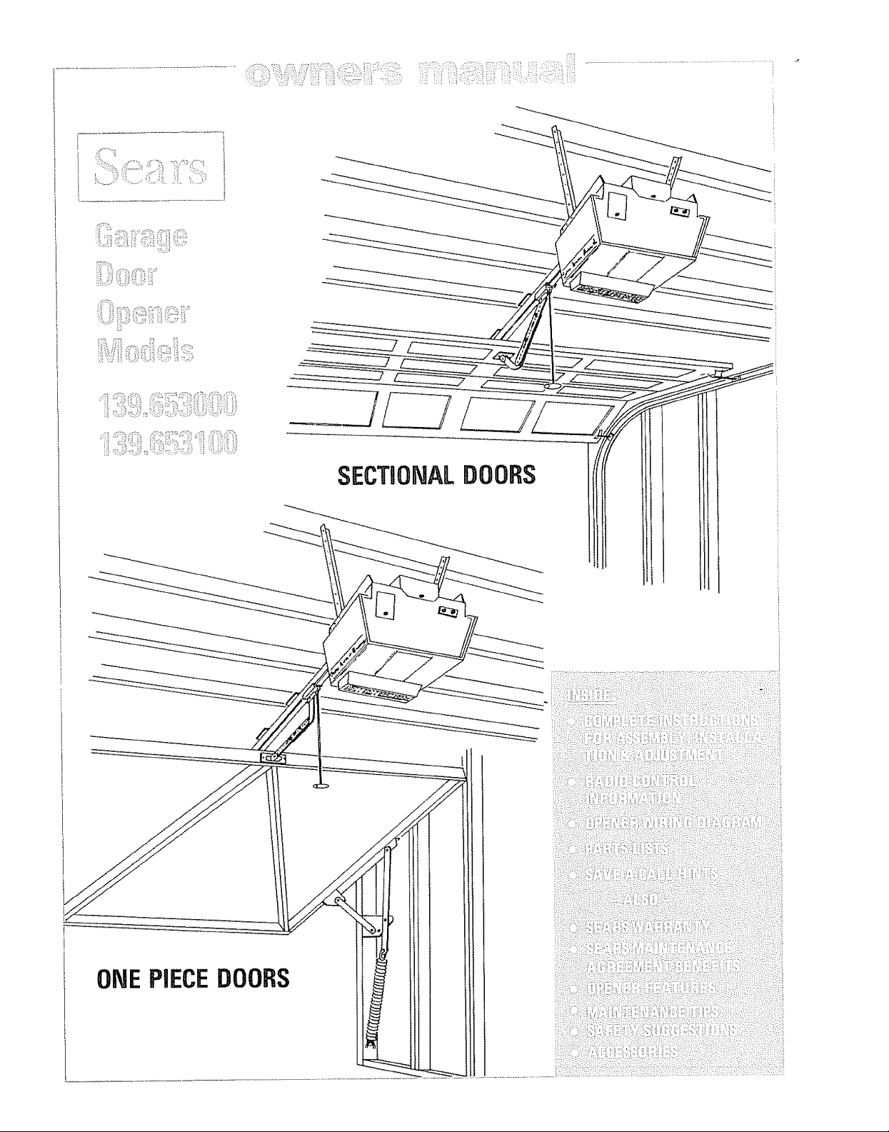
Craftsman 139653100, 139653000 Owner’s Manual
S__kL_i
]
_!iii___i!_i_iiii_i!i_:_ii__:_!__:_'::_s:_'_i
SECTgOHALDOORS
ONEPIECEDOORS
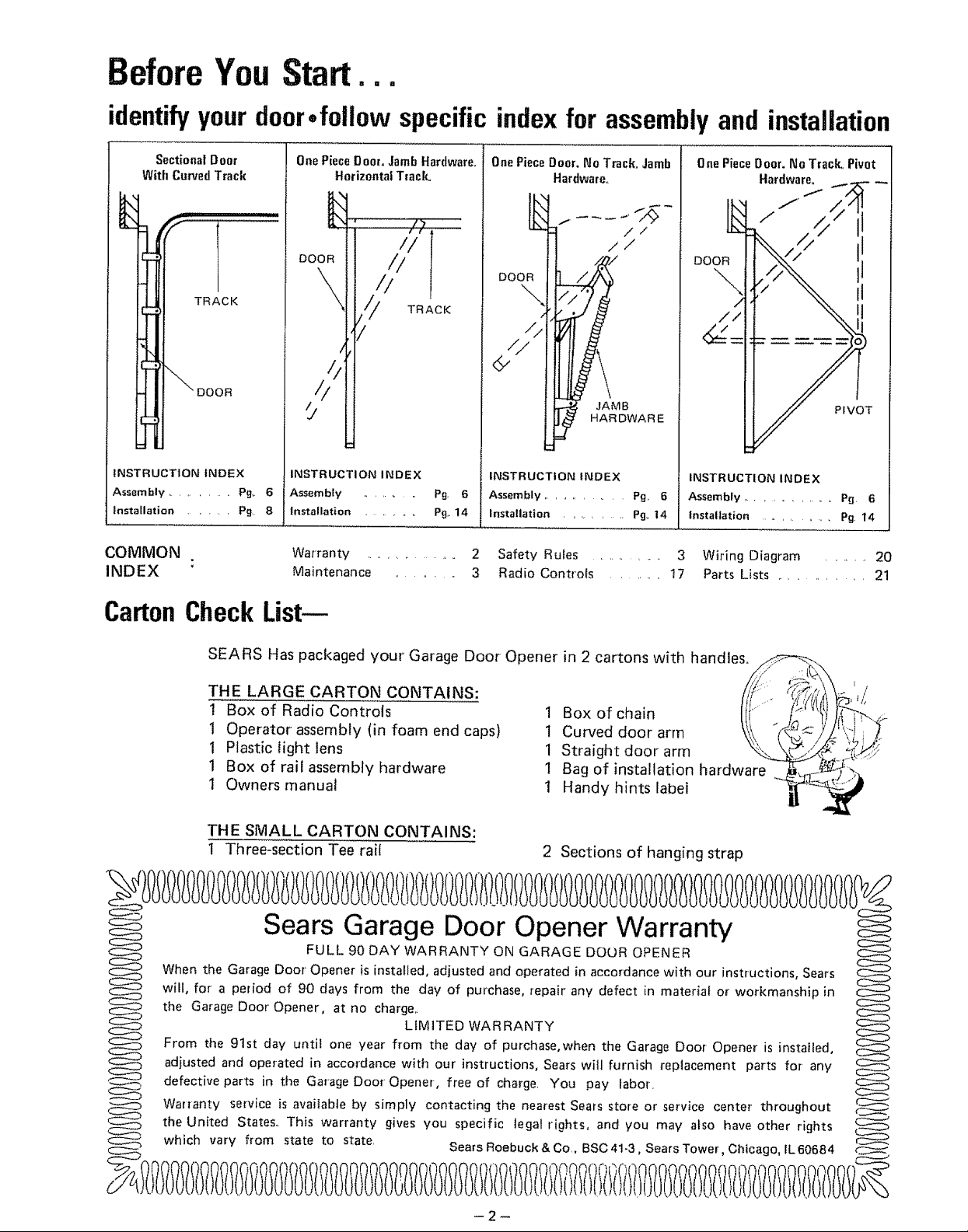
BeforeYouStart.,.
identify your door
Sectional DDOt
With Curved Track
UX
gx
TRACK
DOOR
iNSTRUCTiON INDEX
Assembly ......... Pg_ 6
installation ...... Pg, 8
COMMON
INDEX :
•follow specificindexfor assemblyand installation
One Piece Door. Jamb Hardware_
Horizontal Track°
,,/_, ,,
/il
DOOR
\
\
\
/ TRACK
!
One Piece Door, No Track. Jamb
Hardware,,
//
//
One Piece Door. No Track, Pivot
Hardware,
.f
/
DOOR
\
//
//
//
9
iNSTRUCTION INDEX
Assembly ......... pg. 6
installation ....... Pg., 14
Warranty ............ 2 Safety Rules ........... 3 Wiring Diagram ....... 20
Maintenance ......... 3 Radio Controls ........ 17 Parts Lists ............. 21
INSTRUCTION iNDEX
Assembly ........... pg, 6
Installation .......... Pg. 14
JAMB
HARDWARE
INSTRUCTION INDEX
Assembly .............. P_ 6
Installation ............ Pg 14
PIVOT
CartonCheckList--
SEARS Has packaged your Garage Door Opener in 2 cartons with handles,,_
THE LARGE CARTON CONTAINS: "_J_!Ji_i!#_
1 Box of Radio Controls I Box of chain
1 Operator assembly (in foam end caps) 1 Curved door arm _,_ '
1 Plastic light lens 1 Straight door arm
1 Box of rail assembly hardware 1 Bag of installation hardware
1 Owners manual 1 Handy hints labeF
THE SMALL CARTON CONTAINS:
I Three-section Tee rai!
Sears Garage Door Opener Warranty
FULL 90 DAY WARRANTY ON GARAGE DOOR OPENER
When the Garage Door Opener is installed, adjusted and operated in accordance with our instructions, Sears
will, for a period of 90 days from the day of purchase, repair any defect in material or workmanship in
the Garage Door Opener, at no charge,.
From the 91st day until one year from the day of purchase, when the Garage Door Opener is instatled,
adjusted and operated in accordance with our instructions, Sears will furnish replacement parts fm any
defective parts in the Garage Door Opener, free of charge. You pay labor,
Warranty service is available by simply contacting the nearest Sears store or service center throughout
the United States., This warranty gives you specific tegal rights, and you may also have other rights
which vary from state to state. Sears Roebuck & Co., BSC 41-3, Sears Tower, Chicago, _L60684
2 Sections of hanging strap
LIMITED WARRANTY
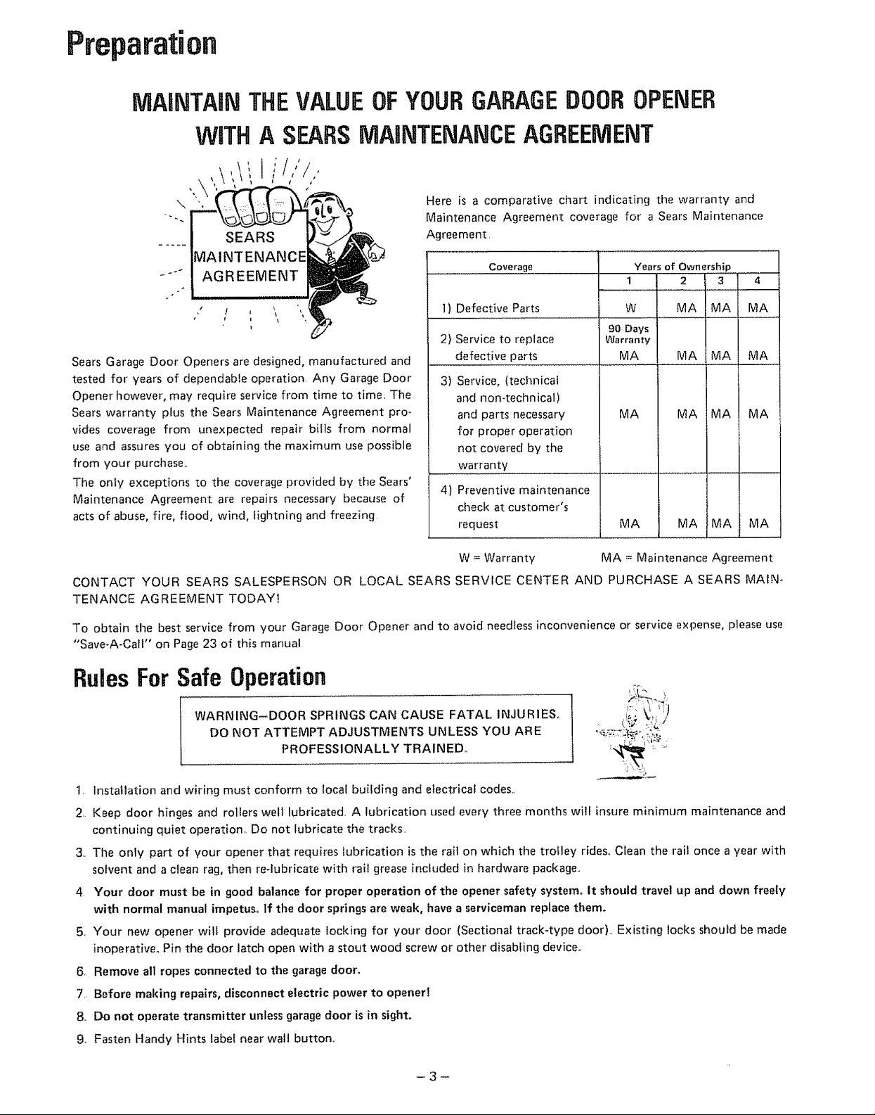
Preparation
MAiNTAiN
THEVALUEOFYOURGARAGEDOOROPENER
MAINTENANCEAGREEMENT
\
.... AGREEMENT
,' l \ 1) Defective Parts W
Sears Garage Door Openers are designed, manufactured and defective parts MA
tested for years of dependable operation Any Garage Door
Opener however, may require service from time to time, The
Sears warranty plus the Sears Maintenance Agreement pro m
vides coverage from unexpected repair bills from normal
use and assures you of obtaining the maximum use possible
from your purchase,,
The only exceptions to the coverage provided by the Sears'
Maintenance Agreement are repairs necessary because of
acts of abuse, fire, flood, wind, lightning and freezing.
Here is a comparative chart indicating the warranty and
Maintenance Agreement coverage for a Sears Maintenance
Agreement
..................Coverage Years of Ownership
2) Service to replace Warranty
3) Service, (technical
and non-technical)
and parts necessary
for proper operation
not covered by the
warranty
4) Preventive maintenance
check at customer's
request
90 Days
MA MA MA MA
MA MAiMA MA
1 2 3 4
MA MA MA
MA MA MA
W = Warranty MA = Maintenance Agreement
CONTACT YOUR SEARS SALESPERSON OR LOCAL SEARS SERVICE CENTER AND PURCHASE ASEARS MAIN-
TENANCE AGREEMENT TODAY!
To obtain the best service from your Garage Door Opener and to avoid needless inconvenience or service expense, please use
"Save-A-Call" on Page 23 of this manual
RulesFor Safe Operation
WARNING-DOOR SPRINGS CAN CAUSE FATAL INJURIES°
DO NOT ATTEMPT ADJUSTMENTS UNLESS YOU ARE
PROFESSIONALLY TRAINED.
t, Installation and wiring must conform to local building and electrical codes.,
2, Keep door hinges and rollers well lubricated, A lubrication used every three months wilf insure minimum maintenance and
continuing quiet operation. Do not lubricate the tracks,
3,, The only part of your opener that requires lubrication is the rail on which the trolley rides., Clean the rail once a year with
solvent and a clean rag, then re-lubricate with rail grease included in hardware package.,
4, Your door must be in good balance for proper operation of the opener safety system. It should travel up and down freely
with normal manual impetus° If the door springs are weal{, have a serviceman replace them_
5o Your new opener will provide adequate locking for your door (Sectional track-type door), Existing locks should be made
inoperative° Pin the door latch open with a stout wood screw or other disabling device°
6, Remove all ropes connected to the garage door.
7,, Before making repairs, disconnect electric power to opener!
8,, Do not operate transmitter unless garage door is in sight.
g, Fasten Handy Hints label near walt button,,
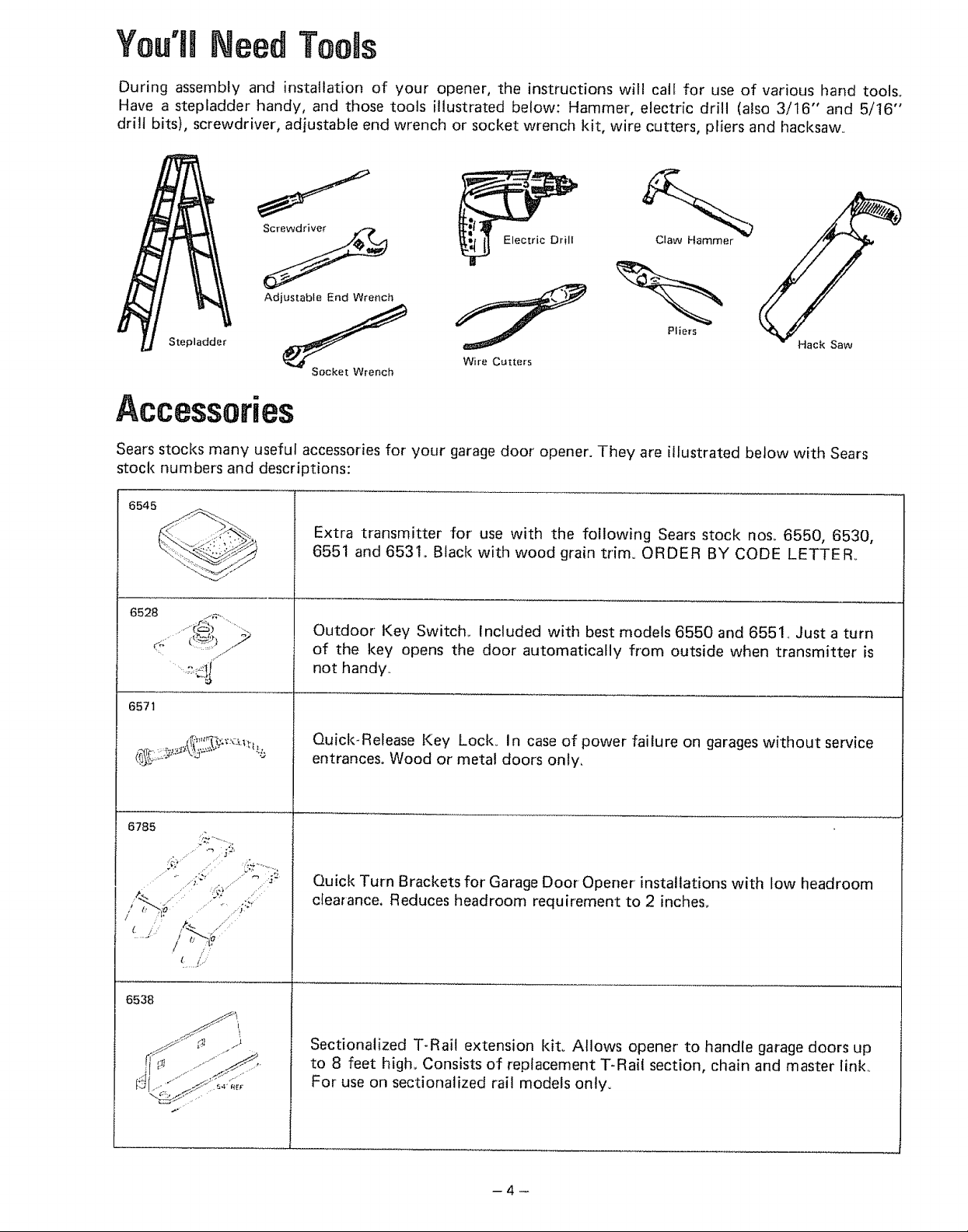
You'll Need Toels
During assembly and installation of your opener, the instructions will call for use of various hand tools_
Have a stepladder handy, and those tools illustrated below: Hammer, electric drill (also 3/16" and 5/16"
drill bits), screwdriver', adjustable end wrench or socket wrench kit, wire cutters, pliers and hacksaw..
Adjustable End Wrench
Stepladder
Socket Wrench
Wire Cutters
Pliers
Accessories
Sears stocks many useful accessories for your garage door' opener. They are illustrated below with Sears
stock numbers and descriptions:
6545
Extra transmitter for use with the following Sears stock nos, 6550, 65.30,
6551 and 6531., Black with wood grain trim° ORDER BY CODE LETTER°
6528 j_,....
6571
f4,_
J (_-.3) .......
Outdoor Key Switch., Included with best models 6550 and 6551.. Just a turn
of the key opens the door automatically from outside when transmitter' is
not handy..
Quick-Release Key Lock. In case of power failure on garages without service
entrances° Wood or metal doors only.
6785
6538
Quick Turn Brackets for Garage Door Opener installations with low headroom
clearance, Reduces headroom requirement to 2 inches.
Sectionalized T-Rail extension kit. ALlows opener to handle garage doors up
to 8 feet high,. Consists of replacement T-Rail section, chain and master link.,
For use on sectionalized rail models only.
.......J
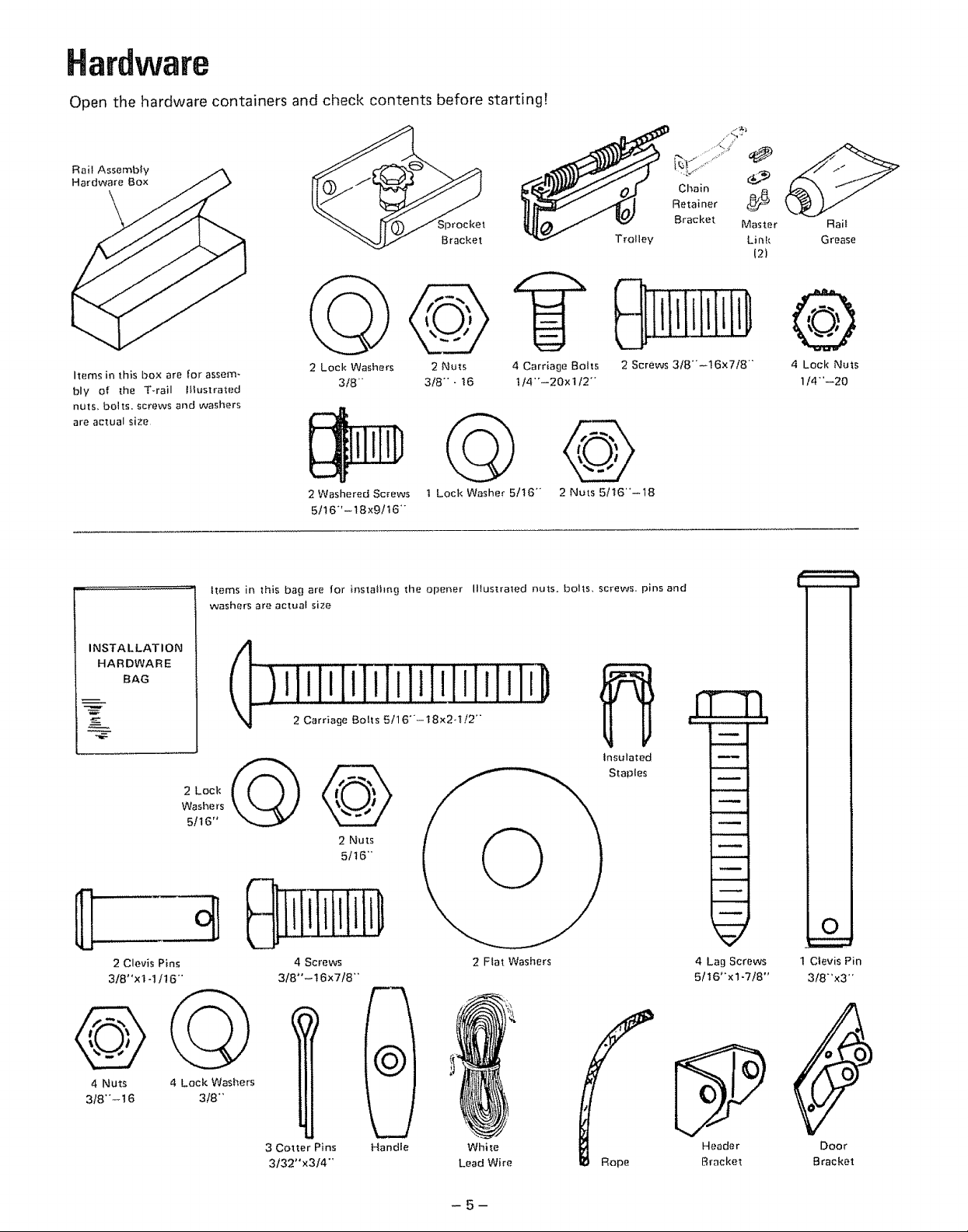
Hardware
Open the hardware containers and check contents before startingF
Rail Assembly
Hardware Box
Trolley
Chain
Retainer
Bracket
Master
Link
12)
Rait
Grease
@
Items in this box are for assem- 2 Nuts
bly of the T.rail IHustrated 3/8--16
nuts, bolts, screws and washers
are actual size
Items in this bag are for instalhng the opener Illustrated nuts. bolts, screws, pins and
washers are actual size
INSTALLATION
HARDWARE
BAG
2 Lock
Washers
5/16"
) _I_IiIi_w!_I_1_iiii]]]_
2 Lock Washers
3f8"
2 Washered Screws
5116"'-18x9tt6""
2 Nuts
51t6"
t Lock Washer 5!16-
4 Carriage Bolts
1!4'°-20x 1/2'"
2 Nuts 5/t6--18
2 Screws 3/8"'-16x7/8"
Insulated
Staples
4 Lock Nuts
1/4--20
2 Clevis Pins
318"xl -1/t6"
4 Nuts
3/8-- t 6
4 Lack Washers
3!8"'
4 Screws
3/8"-t6x7/8"
3 Cotter Pins Handle
3132"x3/4-
l
2 Ftat Washers 4 Lag Screws
5/t6"xl-7!8"
..5__ "-
'_' Header Door
Lead Wire Rope Bracket Bracket
Clevis Pin
318'x3"
-5-
O
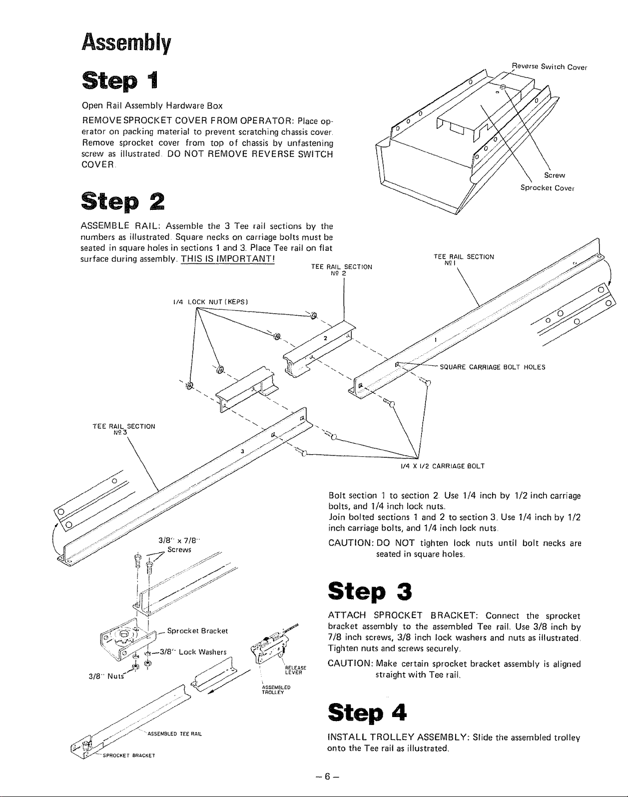
Assembly
Step 1
Open Rail Assembly Hardware Box
REMOVE SPROCKET COVER FROM OPERATOR: Place op-
erator on packing material to prevent scratching chassis cover.
Remove sprocket cover from top of chassis by unfastening
screw as illustrated. DO NOT REMOVE REVERSE SWITCH
COVER,
ASSEMBLE RAIL: Assemble the 3 Tee rail sections by the
numbers as illustrated. Square necks on carriage bolts must be
seated in square holes in sections t and 3. Place Tee rail on flat
surface during assembly,. THIS IS IMPORTANT!
1/4 LOCK NUT (KEPS)
TEE RAIL SECTION
N_-2
TEE RAIL SECTION
N£1
Reverse Switch Cover
Screw
Sprocket Cover
TEE RAIL SECTION
N£3
R_:LEASE
: LEVER
_SSEMBL_D
TROLLEY
SQUARE CARRIAGE BOLT HOLES
I/4 X I/2 CARRIAGE BOLT
Bolt section 1 to section 2, Use 1/4 inch by 1/2 inch carriage
bolts, and !/4 inch loci( nuts.
Join bolted sections 1 and 2 to section 3, Use 1/4 inch by 1/2
inch carriage bolts, and 1/4 inch lock nuts,
CAUTION: DO NOT tighten lock nuts until bolt necks are
seated in square holes,,
Step 3
ATTACH SPROCKET BRACKET: Connect the sprocket
bracket assembly to the assembFed Tee rail Use 3/8 inch by
7/8 inch screws, 3/8 inch lock washers and nuts as itlust[ated,
Tighten nuts and screws securely..
CAUTION: Make certain sprocket bracket assembly is aligned
straight with Tee rait,
Step 4
INSTALL TROLLEY ASSEMBLY: Slide the assembled trolley
onto the Tee rait as illustrated,
-6-
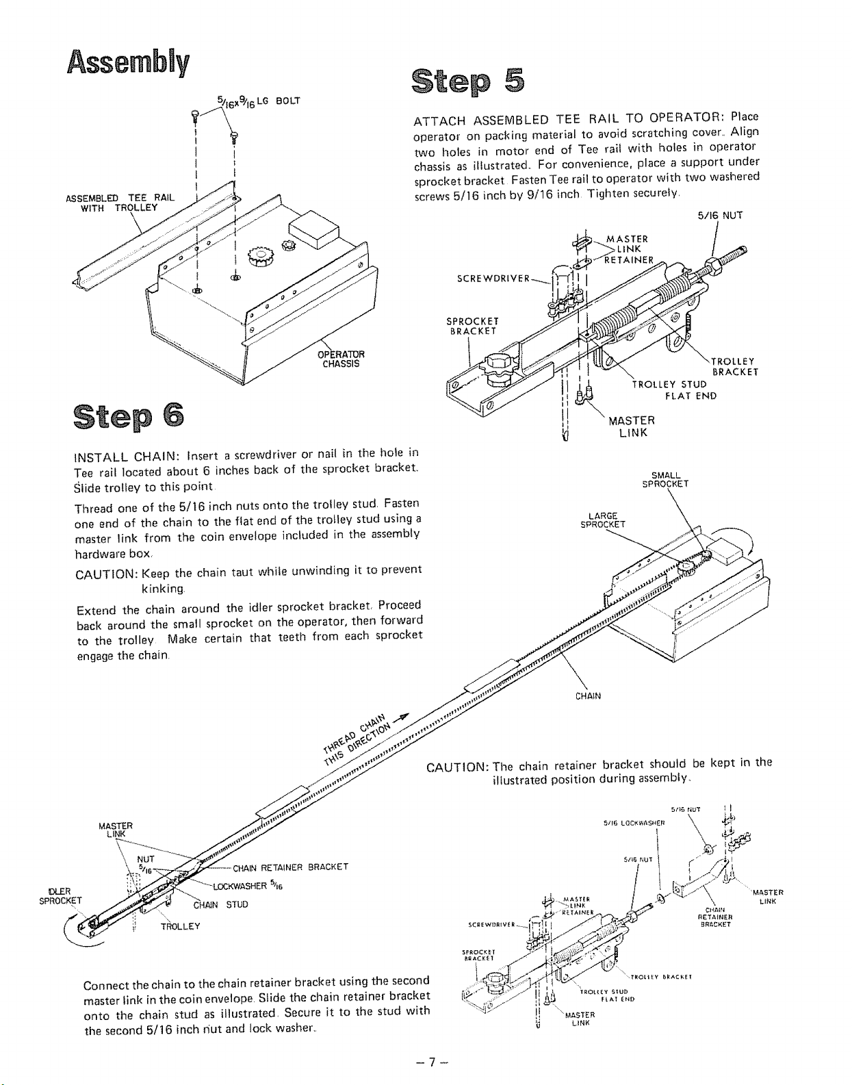
Assembty
'i6x_t6 LG BOLT
ASSEMBLED TEE RAIL
WITH TROLLEY
OPERATOR
CHASSIS
INSTALL CHAIN: Insert a screwdriver or nail in the hole in
Tee rai! located about 6 inches back of the sprocket bracket,,
Slide trolley to this point
Thread one of the 5/16 inch nuts onto the trolley stud Fasten
one end of the chain to the fiat end of the t_'olley stud using a
master link from the coin envelope included in the assembly
hardware box,
CAUTION: Keep the chain taut white unwinding it to prevent
kinking
Extend the chain around the idler sprocket bracket, Proceed
back around the small sprocket on the operator, then forward
to the trolley Make certain that teeth from each sprocket
engage the chain
5
ATTACH ASSEMBLED TEE RAIL TO OPERATOR: Place
operator on packing material to avoid scratching cover,, Align
two holes in motor end of Tee rail with holes in operator
chassis an illustrated, For convenience, place a support under
sprocket bracket Fasten Tee rail to operator with two washered
screws 5/16 inch by 9/16 inch Tighten securely,
5/I6 NUT
SCREWDRIV
SPROCKET
BRACKET
\TROLLEY
BRACKET
MASTER
LARGE
SPROCKET
TROLLEY STUD
FLAT END
LINK
SMALL
SPROCKET
DLER
SPROCKET
MASTER
LINK
RETAINER BRACKET
DC_WASHER_6
CHiN STUb
TROLLEY
J
Connect the chain to the chain retainer bracket using the second
master tink in the coin envelope Slide the chain retainer bracket
onto the chain stud as illustrated Secure it to the stud with
the second 5/16 inch nut and lock washer,,
CAUTION: Tile chain retainer bracket should be kept in the
illustrated position during assembiy_
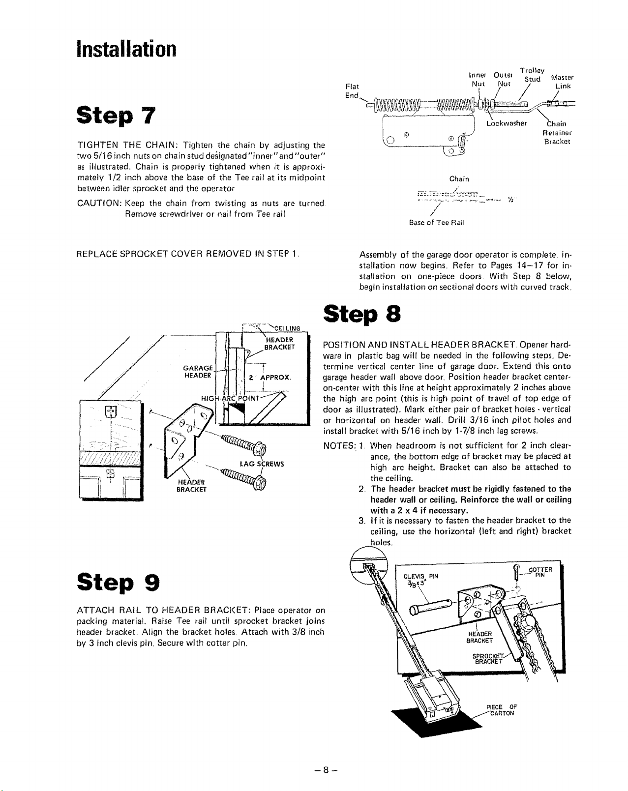
Installation
Step 7
TIGHTEN THE CHAIN: Tighten the chain by adjusting the
two 5/16 inch nuts on chain stud de_ignated"inner" and "outer"
as illustrated,, Chain is propmty tightened when it is approxi-
mately 1/2 inch above the base of the Tee rait at its midpoint
between idler sprocket and the operator
CAUTION: Keep the chain from twisting as nuts are turned
Remove screwdriver or nait from Tee rail
Chain
/
Base of Tee Rail
REPLACE SPROCKET COVER REMOVED IN STEP 1,
GARAGE
HEADER
" +._ LAG SCREWS
HEADER _"_
BRACKET
Assembly of the garage door operator is complete in-
statlation now begins+ Refer to Pages t4-17 for in-
stallation on one-piece doors, With Step 8 below,
begin installation on sectional doors with curved track,
Step 8
POSITION AND INSTALL HEADER BRACKET. Opener"hard-
ware in plastic bag will be needed in the following steps,, De-
termine vertical center" line of garage door+ Extend this onto
garage header wall above door+ Position header bracket center-
on-center with this line at height approximately 2 inches above
the high arc point (this is high point of travel of top edge of
door as illustratedL Mark either' pair of bracket holes - vertical
or horizontal on header" watlo Drill 3/16 inch pilot holes and
instatl bracket with 5/16 inch by 1-7/8 inch lag screws,.
NOTES: t, When headroom is not sufficient for 2 inch clear-
ance, the bottom edge of bracket may be placed at
high arc height. Bracket can also be attached to
the ceiling+
2,, The header bracket must be rigidly fastened to the
header' walt or ceiling. Reinforce the wall or ceiling
with a2 x 4 if necessary.
& If it is necessary to fasten the header bracket to the
ceiling, use the horizontal (left and right) bracket
holes°
Step 9
ATTACH RAIL TO HEADER BRACKET: Place operator on
packing material° Raise Tee rail until sprocket bracket joins
header bracket, Align the bracket holes, Attach with 3/8 inch
by 3 inch clevis pin, Secure with cotter pin+
PIN
PIECE OF'
 Loading...