

Craftsman 13953974SRT Owner’s Manual
Owner's
Manual
Model No.
139.53974SRT
For Residential Use
Only
ICRRFTSNRN1
GARAGE DOOR OPENER
Caution:
Read and follow all
safety rules and
operating instructions
before first use of this
product.
Fasten the manual
near the garage door
after installation,
1/2 HP
• Safety Precautions
• Assembly
• Installation
• Adjustment
• Care and Maintenance
• Operation
• Troubleshooting LIBRARY:
• Parts List
Sears, Roebuck and Co., Hoffman Estates, IL 60179 U.S.A.
Mist(Mr Craftsman website: www.sears.com/craftsman
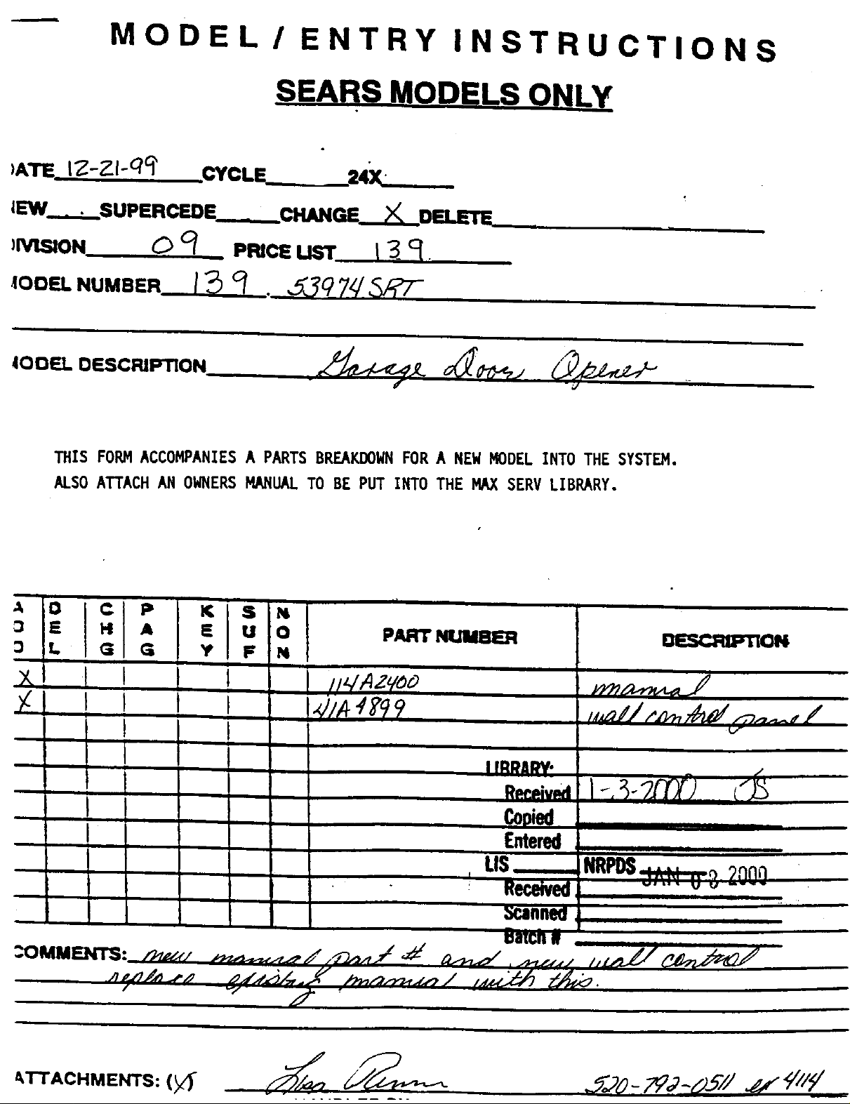
--- MODEL ! ENTRY INSTRUCTIONS
O
_ATEtZ-ZI-qq' CYCLE 14X._.__.
JEW • SUPERCEDE CHANGE_DELETE,
)_..._ON O q PmCEusr 13__.
IODELNUMBER I_ I • J397_
THIS FORM ACCOMPANIES A PARTS BREAKDOWN FOR A NEW MODEL INTO THE SYSTEM.
ALSO ATTACH AN OWNERS MANUAL TO BE PUT INTO THE M/bXSERV LIBRARY.
C
PI
A :O
L
G
G Y F N
PART NIJMBER
ri_,.iON
t
I iBr)An,v-
i-,
Copi_
Entered
US-_.-.
II I I'll I I I
I II I I
Received_ "
:OMMENTS:
/
tk'I-i'ACHMENTS: (y_ _._,,.20 - _(P-O-J _'/i_ _///_/
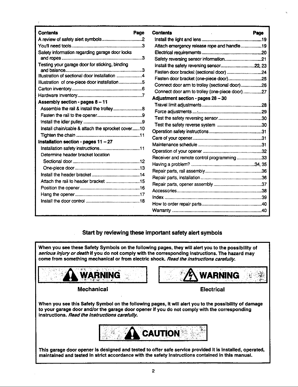
Contents Page
A reviewofsafetyalert symbols.................................2
You'llneedtools..........................................................3
Safety informationregardinggarage doorlocks
and ropes..................................................................3
Testingyourgaragedoorforsticking,binding
and balance...............................................................3
Illustrationofsectionaldoor installation.....................4
Illustrationofone-piecedoor installation...................5
Carton inventory..........................................................6
Hardware inventory.....................................................7
Assembly section - pages 8 - 11
Assemblethe rail&installthe trolley........................8
Fastentherailto the opener.....................................9
Installthe idlerpulley................................................9
Installchain/sable&attach the sprocketcover......10
Tightenthe chain....................................................11
Installation section - pages 11 - 27
Installationsafety instructions.................................11
Determineheaderbracketlocation
Sectionaldoor.......................................................12
One-piecedoor.....................................................13
Installtheheaderbracket.......................................14
Attachthe railtoheaderbracket............................15
Positiontheopener.................................................16
Hangtheopener.....................................................17
Installthedoorcontrol............................................18
Contents Page
Installthe lightandlens.................................................19
Attachemergencyreleaseropeand handle.................19
Electricalrequirememts.................................................20
Safety reversingsensorinformation............................. 21
InstaUthe safetyreversingsensor...........................22, 23
Fastendoorbracket(sectionaldoor)............................24
Fastendoorbracket(one-piecedoor)...........................25
Connect doorarm totrolley(sectionaldoor).................26
Connectdoorarmtotrolley(one-piecedoor)...............27
Adjustment section - pages 28 - 30
Travel limitadjustments.................................................28
Forceadjustments....:....................................................29
Test thesafety reversingsensor...................................30
Test the safetyreversesystem....................................30
Operationsafety instructions...........................................31
Care of youropener.........................................................31
Maintenanceschedute....................................................31
Operationofyouropener................................................32
Receiverand remotecontrolprogramming....................33
Havinga problem?....................................................34, 35
Repair parts,railassembly..............................................36
Repair parts,installation..................................................36
Repair parts,openerassembly.......................................37
Accassories......................................................................38
Index................................................................................39
How to orderrepairparts.................................................40
Warranty..........................................................................40
Start by reviewing these important safety alert symbols
When you see these Safety Symbols on the following pages, they will alert you to the possibility of
serious injury or death if you do not comply with the corresponding instructions. The hazard may
come from something mechanical or from electric shock. Read the instructions carefully.
[ WARNING J
Mechanical
When you see this Safety Symbol on the following pages, It will alert you to the possibility of damage
to your garage door and/or the garage door opener ifyou do not comply with the corresponding
instructions. Read the instructions carefully.
Electrical
CAUTION
This garage door opener ls designed and tested to offer safe service provided It Is Installed, operated,
maintained and tested in strict accordance with the safety instructions contained in this manual.
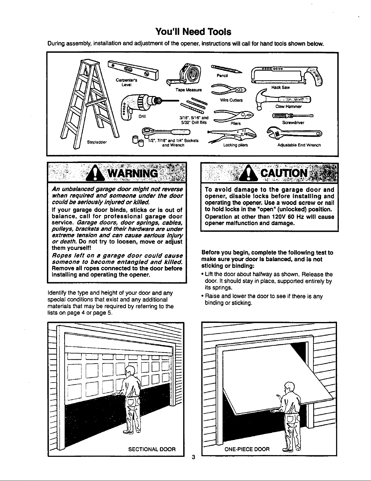
You'll Need Tools
During assembly,installationand adjustmentofthe opener, instructionswillcallfor handtoolsshown below.
Stepladder
An unbalanced garage door might not reverse
when required and someone under the door
could be seriously injured or killed.
If your garage door binds, sticks or is out of
balance, call for professional garage door
service. Garage doors, door springs, cables,
pulleys, brackets and their hardware are under
extreme tension and can cause serious injury
or death. Do not try to loosen, move or adjust
them yourself!
Ropes left on a garage door could cause
someone to become entangled and killed.
Remove all ropes connected to the door before
installing and operating the opener.
Identify the type and height of your door and any
specialconditionsthat existand any additional
materials that may be required by referring to the
lists on page 4 or page 5.
Adjustal_e End Wrench
To avoid damage to the garage door and
opener, disable locks before installing and
operating the opener, Use a wood screw or nail
to hold locks in the "open" (unlocked) position.
Operation at other than 120V 60 Hz will cause
opener malfunction and damage.
Before you begin, complete the following test to
make sure your door Is balanced, and is not
sticking or binding:
• Liftthe doorabouthalfwayas shown. Release the
door.Itshouldstayin place,supportedentirelyby
itssprings.
• Raise andlowerthe door to see if there isany
binding or sticking.
3
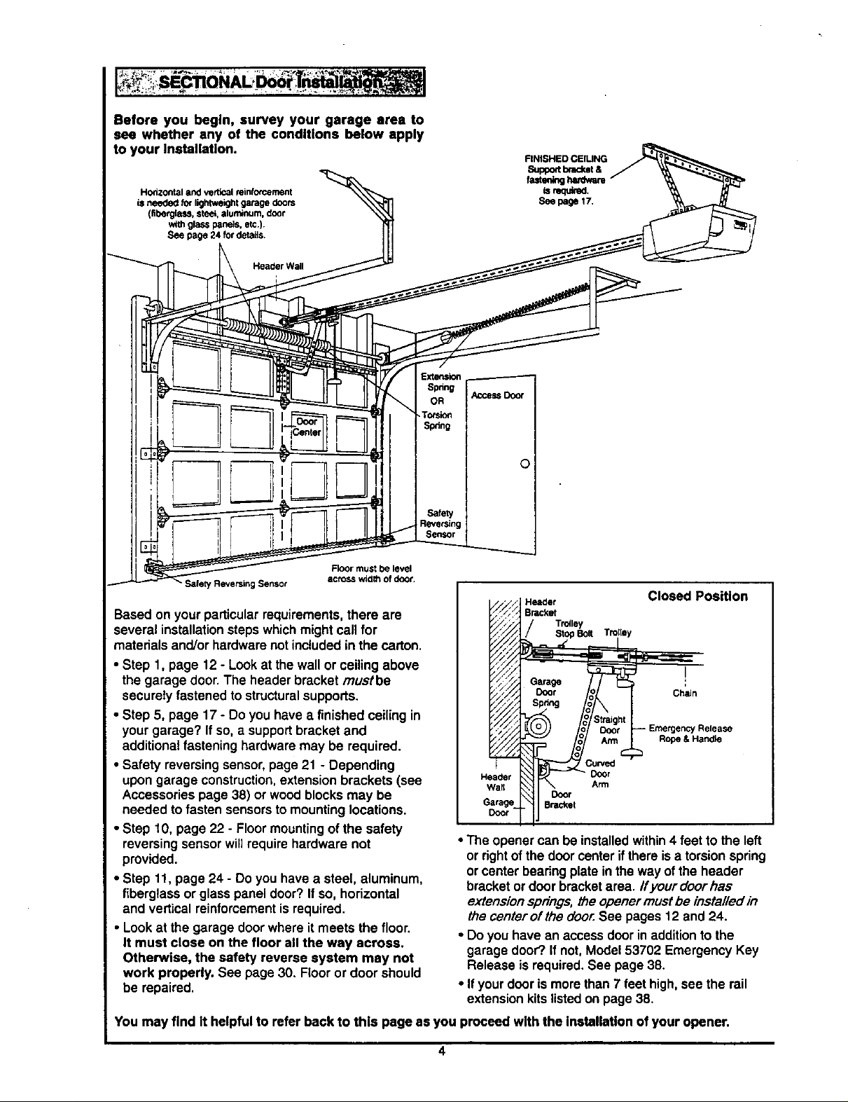
Beforeyoubegin,surveyyourgarageareato
seewhetheranyoftheconditionsbelowapply
toyourInstallation.
Horizontal and vertical rein_,T.ement
is needed _€ lightweight garage doors
(fiberglass, stee_,aluminum, door
withglass panels, etc.).
See page 24 fordeta_s.
Header Wall
Extensk>n
OR Access Door
Spring _el
Torsion
S_ng t
Safety I
ReversingI
Sensor I
0
Floor must be level
Safety Reversing Sensor
Based on yourparticular requirements,there are
several installationstepswhichmightcall for
across wld_ of door,
Header
Bracket
Trofley
Stop Bolt Tn
Closed Position
materials and/orhardwarenot includedinthe carton,
• Step 1, page 12 - Lookat the wallor ceilingabove
the garage door.The header bracket rnustbe
securelyfastened to structuralsupports.
• Step 5, page 17 - Do you have a finished ceiling in
yourgarage? If so, a supportbracketand
additionalfastening hardwaremay be required.
• Safety reversingsensor,page21 - Depending
upon garage construction,extensionbrackets (see
Accessoriespage 38) or woodblocksmay be
needed tofasten sensorsto mountinglocations.
Header Door
Wall Arm
Door
Bracket
I
Chain
r Release
Rope & Han_e
• Step 10, page 22 - Floor mountingof the safety
reversingsensorwill require hardware not
provided.
• Step 11, page 24 - Do you have a steel, aluminum,
fiberglass or glass panel door?If so, horizontal
and vertical reinforcementis required.
• Look at the garage door where it meets the floor.
It must close on the floor all the way across.
Otherwise, the safety reverse system may not
work properly. See page 30. Flooror door should
be repaired.
• The openercan be installedwithin4 feet to the left
or rightof the doorcenter ifthere is a torsionspring
orcenterbearing plate in the way ofthe header
bracketordoor bracketarea. ffyourdoorhas
extensionsprings,the openermustbe installed in
thecenter ofthe door.See pages 12 and 24.
• Do youhave an access doorinadditionto the
garage door?,ifnot, Model 53702 Emergency Key
Release is required.See page 38.
• If your door is morethan7 feet high,see the rail
extensionkitslistedon page38.
You may find it helpful to refer back to this page as you proceed with the installation of your opener.
4
One-Piece Door without Track
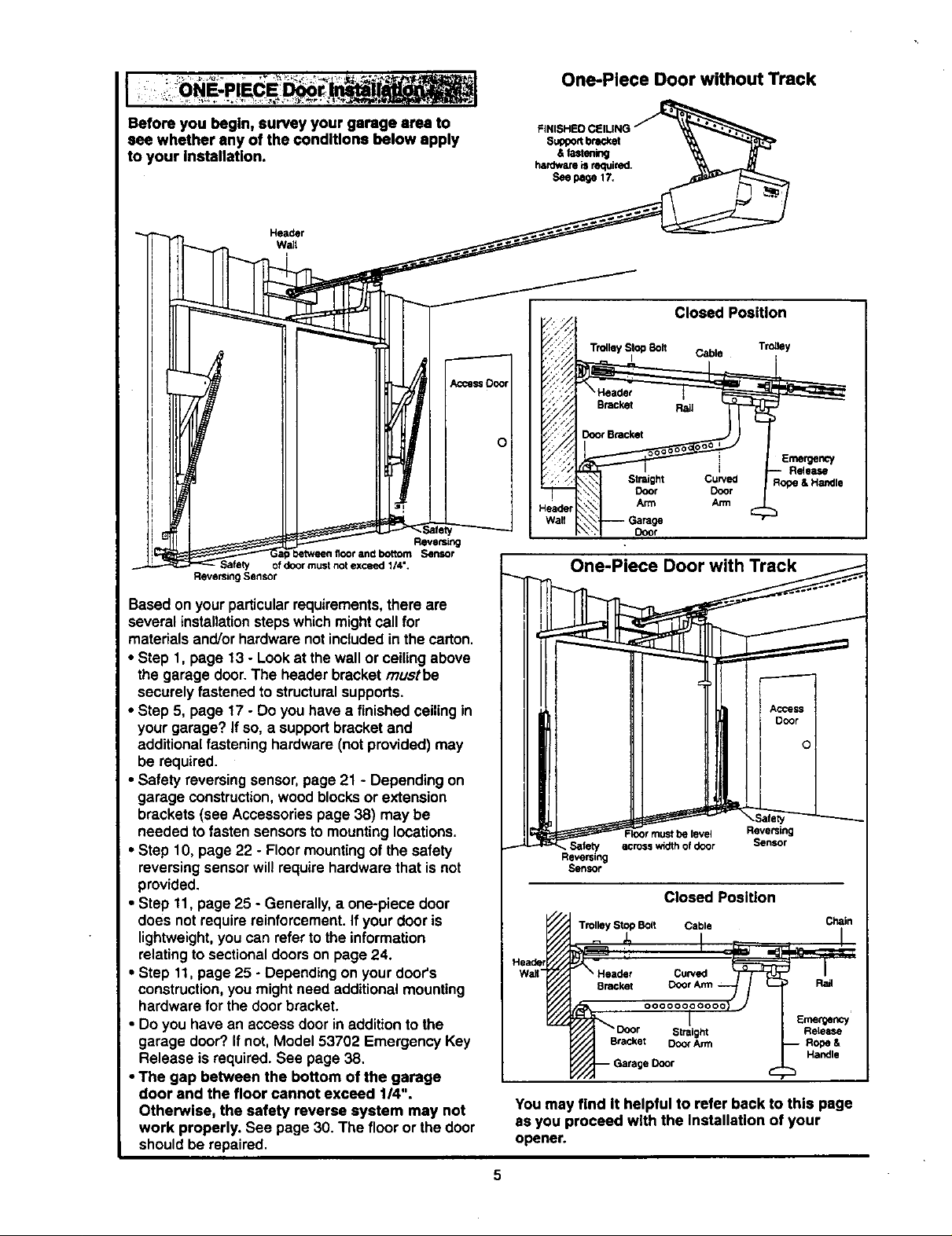
Before you begin, survey your garage area to FNSHEDOEUNO / -_'_,_-_.
see whether any of the conditions below apply superbracket "_
to your installation. . &fastening _, _,
Header
nardwm is required.
See dege 17.
w,l
Zll//
Db':, Door Bracket
Ii II l !11 IIIPl I I I Fi i _i _%.,.
! 7;"; i Emergency
; ,; ,: -_ Slight Curved Rope l Handle
-_ {,. Door Door
Wall \7 Garage
Safely Ofdoor must not exceed 114".
Reversing Sensor
ap between floor and bottom Sensor
Based on yourparticularrequirements,there are
several installatien stepswhichmightcallfor
materials and/orhardware not includedin the carton.
• Step 1, page 13 - Lookat thewall er ceilingabove
the garage door.The header bracket rnustbe
securely fastenedto structuralsupports.
• Step 5, page 17 - Do you have a finished ceiling in
your garage? If so, a support bracketand
additionalfastening hardware (not provided) may
be required.
• Safety reversingsensor,page 21 - Depending on
garage construction,woodblocks or extension
brackets (see Accessoriespage 38) may be
needed tofasten sensors to mountinglocations.
• Step 10, page 22 - Floor mountingof the safety
reversingsensor will require hardwarethat is not
provided.
• Step 11, page 25 - Generally, a one-piece door
does not requirereinforcement.If your door is
lightweight,you can refer to theinformation
relatingtosectionaldoors on page 24.
• Step 11,page 25 - Dependingon your deor's
construction,you might need additionalmounting
hardware for the doorbracket.
• Do you have an access doorin additionto the
garage door?.If not, Model 53702 Emergency Key
Release is required. See page 38.
•The gap between the bottom of the garage
door end the floor cannot exceed 1/4".
Otherwise, the safety reverse system may not
work properly. See page 30. The floor or thedoor
shouldbe repaired.
i
Access
D°_o ---------
Floormustbe level Reversing
Reversing
Sensor
across wio_hof door
Closed Position
Trolley Stop Boll Cable
Chain
Handle
You may find It helpful to refer back to this page
as you proceed with the Installation of your
opener.

Carton Inventory
Your garage door opener is packagedin twocartons whichcontainpartsillustratedbelow,Accessorieswill
depend on model purchased. If anythingismissing,carefullycheckthepackingmaterial. Partsmay be "stuck"in
the foam. Hardware for assemblyand installationis shownon page 7.
StandardControlConsole
Trolley
Chain
Idter Pulley
Rml
Front (header)
Sactlon
Remote Contml with Visor Clip (2)
Spre<:ketCover
Security@Three-Function
/
Sacurlt_ Ks/less EnW
/
Rail
Center/Back
Sact_ne
Door Bracket
Light Lens
Hanging Brackets
J
Safety Sensor
Bracket
Header Bracket
==%
(2) Safety Reversing Sensors
(I Sending Eye and 1 Receiving Eye)
2-Conductor White & White.lack Bell Wire
vim
at_a_ed
6
2-Co_luctor Bell Wire
White &White/ned
Safety Labels
and
literature
Cu_ Door
A,'m Section
Straight Door
Arm Section
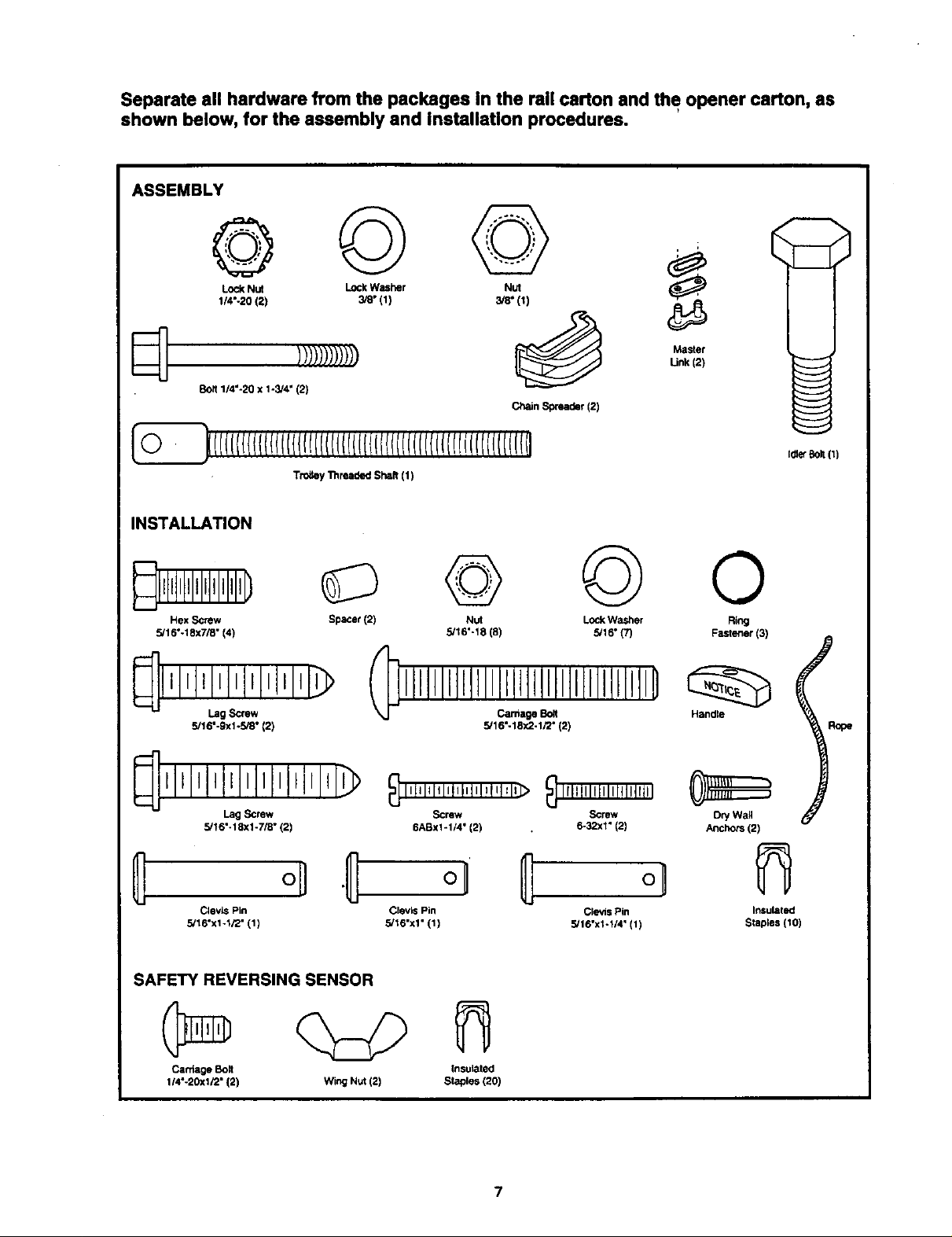
Separate all hardware from the packages In the rail carton and the opener carton, as
shown below, for the assembly end installation procedures.
ASSEMBLY
Lock Nut Lock Washer Nut
1/4"-20 (2) 3/8" (1) 3/8" (I)
q
BOR1/4"-20 x 1-3/4" (2)
Tro_ey Tilreaded ShaR (1)
INSTALLATION
Hex Screw Spacer (2)
5/16"-18x7/8" (4)
l'l,l,l,l,l l,l,l,I>
Lag Screw
5/16"-9xl-5/8" (2)
Lag Screw
5/16"-18xl-7/8" (2)
1!/////////) "n'_i:;
Chain Spreader (2)
© @ o
Nut Lock Washer Ring
5/16"-18 (8) 5/16" (7) Fastener (3)
5/16"-18X2-1/2" (2)
Screw Screw Dry Wag
6ABx1-1/4" (2) 6-32xl" (2) Anchors (2)
ol} o1
CJevisPin Clevis Pin
5/16"x1-1/2" (1) 5/16"x1" (1)
SAFETY REVERSING SENSOR
Catdage Bo_t
1/4"-20Xl/2" (2)
Wing Nut (2) Staples (20)
Clevis Pin Insuleted
5/16"xi-1/4" (1) Staples (10)
Insulated
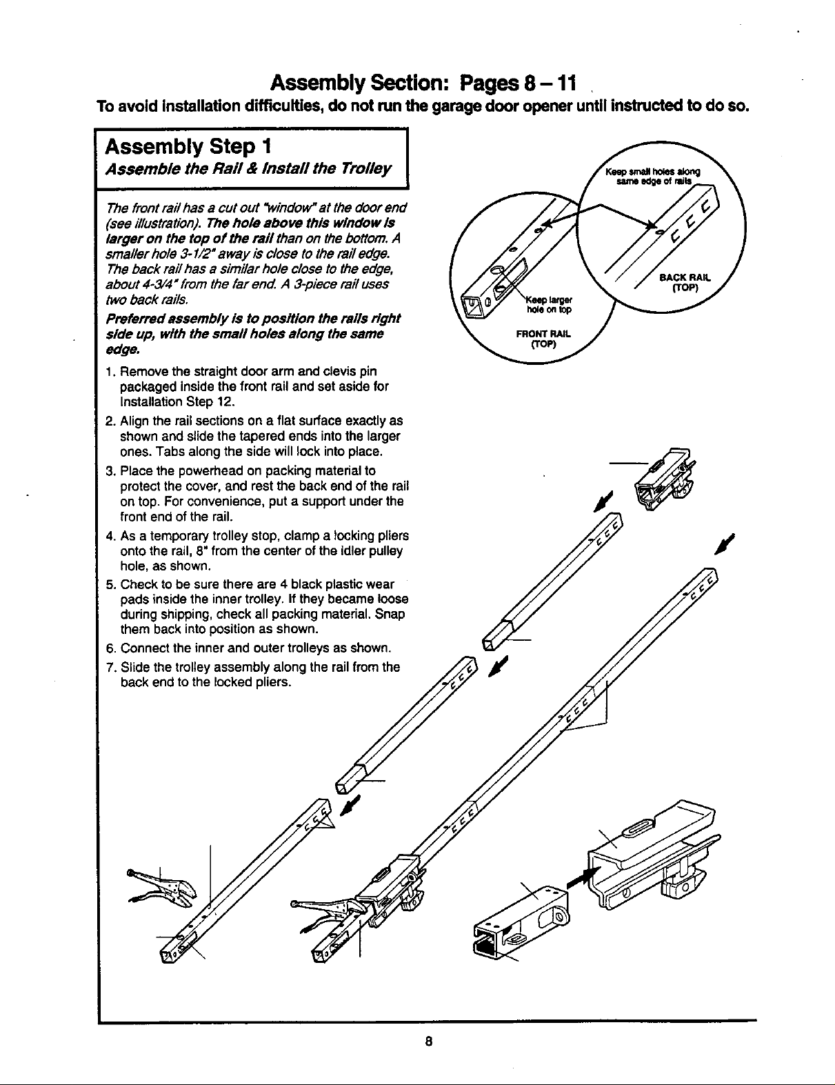
Assembly Section: Pages 8 - 11
To avoid installation difficulties, do not run the garage door opener until instructed to do so.
Assembly Step 1
Assemble the Rail & Install the Trolley
The front railhas a cutout "window'at the doorend
(see illustration). The hole above this window Is
larger on the top of the rail than on thebottom.A
smallerhole 3-1/2" away isclose tothe railedge.
Theback rail has a similar hole close tothe edge,
about 4-3/4" fromthe far end. A 3-piece rail uses
twoback rails.
Preferred assembly is to position the rails right
side up, with the small holes along the same
edge.
1. Remove the straightdoor arm and clevispin
packaged insidethefront rail and set asidefor
InstallationStep 12.
2. Alignthe railsectionson a flat surface exactly as
shownand slide the tapered ends intothe larger
ones.Tabs along the side will lock intoplace.
3, Place the powerhead onpacking materialto
protectthe cover, and restthe backend of the rail
on top. For convenience, put a supportunderthe
front end ofthe rail.
4. As a temporary trolleystop, clamp a locking pliers
ontothe rail, 8"from the center of the idlerpulley
hole, as shown.
5. Check to be sure there are 4 black plasticwear
pads inside the innertrolley. If theybecame loose
duringshipping,check all packingmaterial.Snap
them back intopositionas shown.
6. Connect the inner and outer trolleysas shown.
7. Slide the trolleyassembly along the rail fromthe
back end to the locked pliers.
/
/
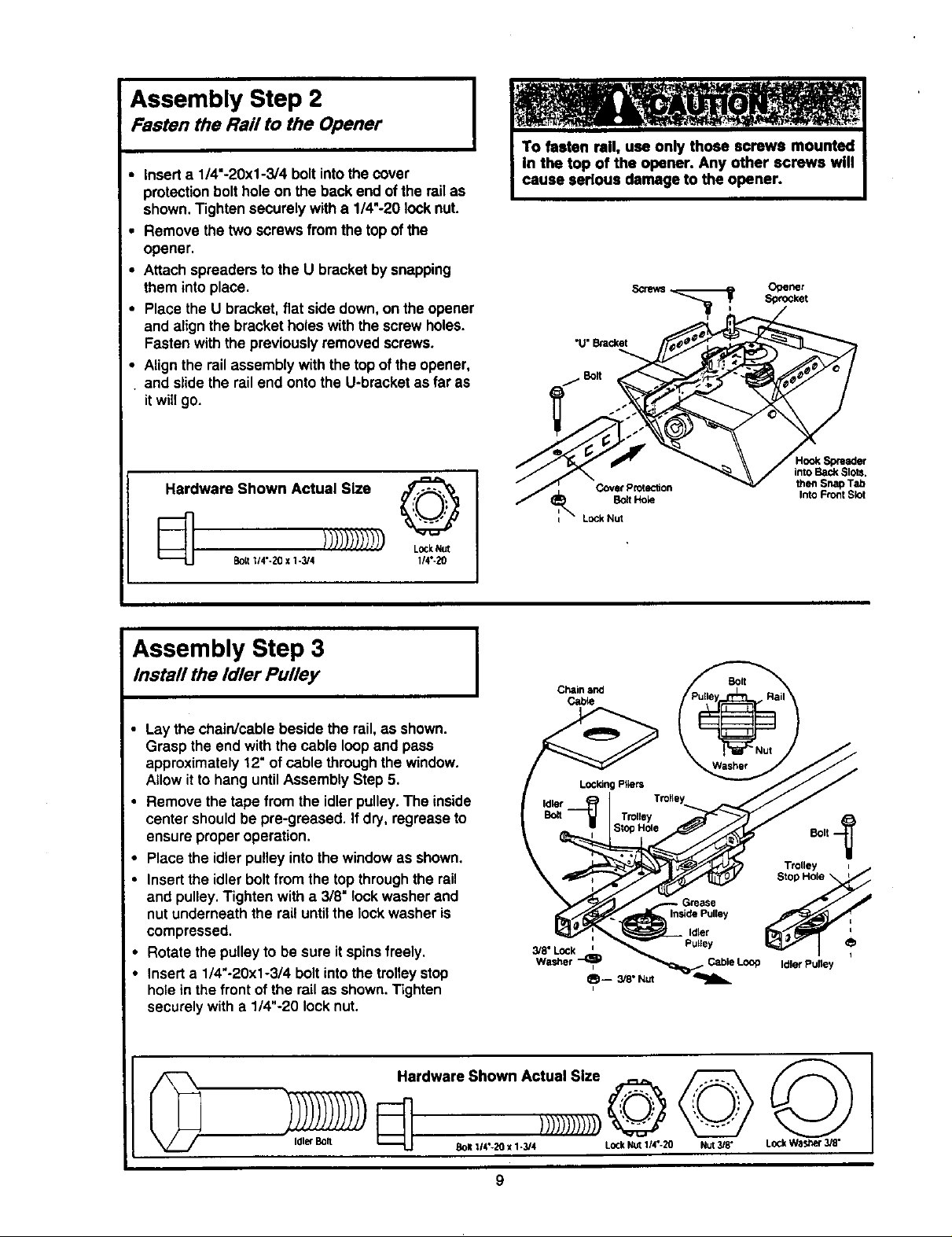
Assembly Step 2
Fasten the Rail to the Opener
• Inserta 1/4"-20xl-3/4 bolt intothe cover
protectionbolthole on the back end ofthe railas
shown.Tighten securelywith a 1/4"-20 locknut.
• Remove the two screws from the top ofthe
opener.
• Attach spreadersto the U bracket bysnapping
them intoplace.
• Place the U bracket, flat side down,on the opener
and alignthe bracketholes withthe screw holes.
Fasten withthe previouslyremoved screws.
• Alignthe railassembly with the topof the opener,
and slide the rail end ontothe U-bracket as far as
itwillgo.
Hardware Shown Actual Size
Covet Protection
Bo_ Hok_
L_k Nut
into Back Slots,
then Snap Tab
Into Front Slot
Bolt 1/4"- _0 x 1-3/4 114"-L>0
1)))))1))!1)
Assembly Step 3
Install the Idler Pulley
Lay the chain/cable beside the rail,as shown.
Grasp the end with the cable loopand pass
approximately 12" ofcable through the window.
Allow it to hang untilAssembly Step 5.
Remove the tape from the idlerpulley. The inside
center shouldbe pre-graased. If dry, regreaseto
ensureproperoperation.
Place the idler pulleyintothe window asshown.
• Insertthe idler boltfrom the topthroughthe rail
and pulley. Tighten witha 3/8" lock washerand
nut underneaththe rail untilthe lockwasher is
compressed.
• Rotate the pulleyto be sure it spinsfreely.
• Insert a 1/4"-20xl-3/4 boltintothe trolleystop
hole in the front of the rail as shown. Tighten
securelywith a 1/4"-20 locknut.
Ttoltsy =
\
Idler _
Inside Pulley
Pugey
Cable Loop Idler Pulley
Stop Hole t
Hardware Shown Actual Size _
Idler Bolt Bolt 114"-20 x 1-3/4 LOCkNut 1/4°-20 Nut 3/8" L_k Wastler 3/8"
9
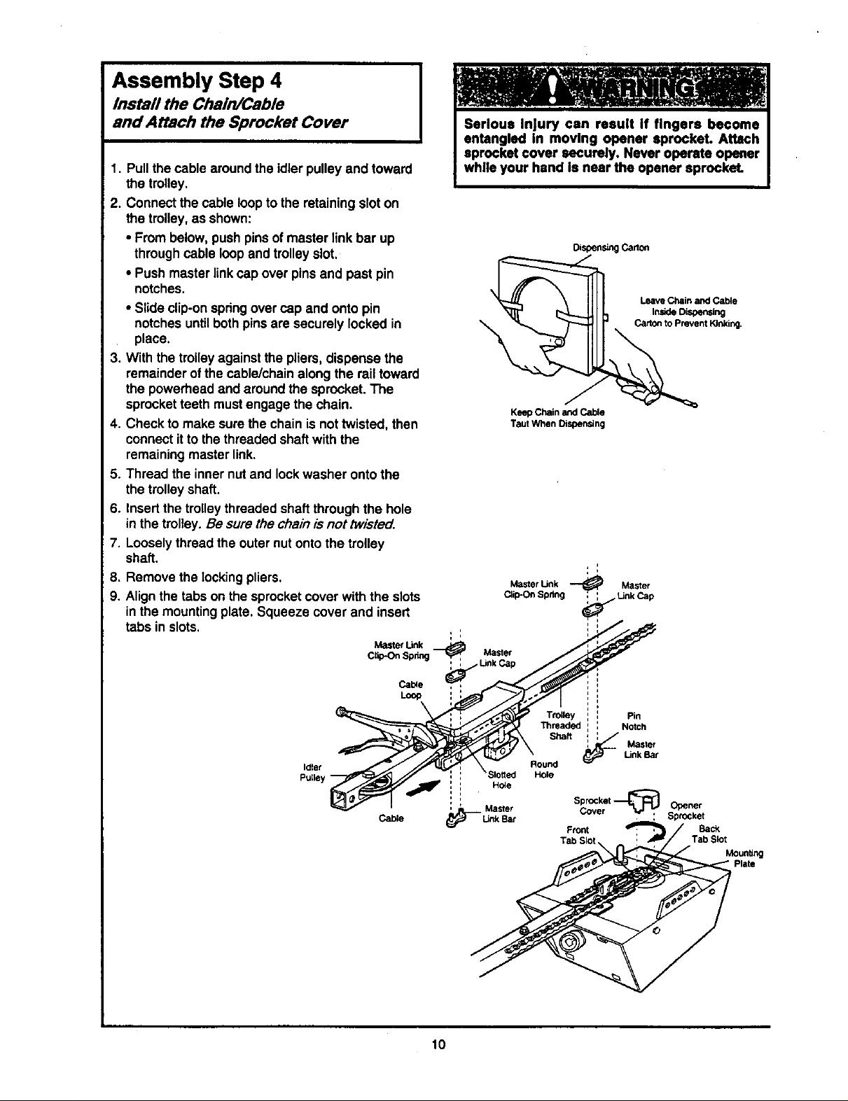
Assembly Step 4
Install the Chain/Cable
and Attach the Sprocket Cover
1. Pullthe cable aroundthe idlerpulley and toward
the trolley.
2. Connect the cableloopto the retaining sloton
thetrolley,as shown:
• From below, pushpins of master link bar up
through cable loopand trolleyslot.
• Push master linkcap over pins and past pin
notches.
• Slideclip-on springover cap and onto pin
notchesuntilboth pins are securely locked in
place.
3. Withthe trolleyagainstthe pliers,dispense the
remainderofthe cable/chain along the rail toward
the powerheadand around the sprocket.The
sprocketteeth must engage the chain.
4. Check to make surethe chain is nottwisted, then
connectitto thethreaded shaftwith the
remainingmaster link.
5. Thread the inner nutand lockwasher ontothe
the trolleyshaft.
6. Insertthe trolleythreaded shaftthrough the hole
inthe trolley.Be sure the chainis not twiste_.
7. Looselythread the outer nutonto the trolley
shaft.
8. Remove the lockingpliers.
9. Align the tabs on the sprocketcover withthe slots
inthe mountingplate. Squeeze cover and insert
tabs in slots.
DiSpensing Canon
Leave Chain and Cable
Inside Dis_oenstng
Carton to Prevent Kinking.
\
Keep Chain and Cable
Taut When Dispensing
, i
Master Link ---_ Master
DiilPOn Spnng _ Link Cap
Idlat
'"_ : , Link Cap
Loop :
r_st_e
10
Hble
Master
(_'_- Link Bat
Trolley : Pin
Threaded : Notch
_ Master
Shaft ,_,
Round
Hole
Sprocket
Cover ---_ Opener
Front _ Back
Tab Skit Tab Slot
Unk Bar
, , SprOcket
Mounting
Plate
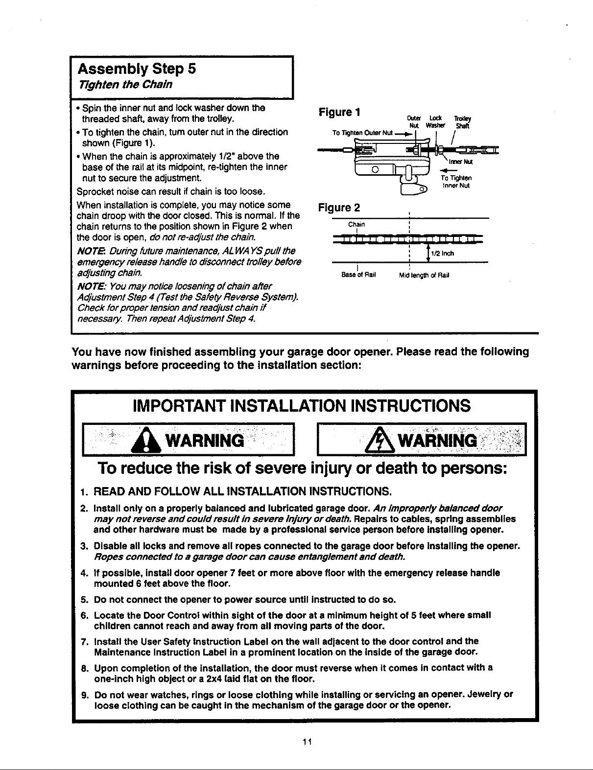
Assembly Step 5
Tighten the Chain
I
• Spin the inner nutand lockwasher down the
threaded shaft, away fromthe trolley.
• To tightenthe chain,turnouternut inthe direction
shown (Figure 1).
•When the chain is approximately1/2" above the
base of the railat its midpoint,re-tightenthe inner
nut tosecure the adjustment.
Sprocket noisecan resultif chainistoo loose.
When installation is complete,you may notice some
chain droopwiththe doorclosed.This isnormal. If the
chain returnstothe positionshownin Figure 2 when
the door is open, do not re.adjust the chain.
NOTE:. During future maintenance,ALWA YSpull the
emergency release handle to disconnecttrolley before
adjusting chain.
NOTE: Youmay noticelooseningof chain after
AdjustmentStep 4 (Test the Safety Reverse System).
Check for proper tensionand readjust chain if
necessary. Thenrepeat AdjustmentStep 4.
You have now finished assembling your garage door opener. Please read the following
warnings before proceeding to the installation section:
Figure I 0=,_ Lo_ r,=_v
Figure 2
Chain
Base of Rail Mid lengltl of Rail
NUt Washer Shaft
i
i
,,
IMPORTANT INSTALLATION INSTRUCTIONS
I ' &WARNING: I I
To reduce the risk of severe injury or death to persons:
1. READ AND FOLLOW ALL INSTALLATION INSTRUCTIONS.
2. Install only on a properly balanced and lubricated garage door. An improperly balanced door
may not reverse and could result In severe Injury or death. Repelrs to cables, spring assemblies
and other hardware must be made by a professional service person before Installing opener.
3. Disable all locks and remove all ropes connected to the garage door before installing the opener.
Ropes connected to a garage door can cause entanglement and death.
4. If possible, install door opener 7 feet or more above floor with the emergency release handle
mounted 6 feet above the floor.
5. Do not connect the opener to power source until instructed to do so.
6. Locate the Door Control within sight of the door at a minimum height of 5 feet where small
children cannot reach and away from all moving parts of the door.
7. Install the User Safety Instruction Label on the wall adjacent to the door control and the
Maintenance Instruction Label in a prominent location on the inside of the garage door.
8. Upon completion of the installation, the door must reverse when it comes in contact with a
one-inch high object or a 2x4 laid flat on the floor.
9. Do not wear watches, rings or loose clothing while installing or servicing an opener. Jewelry or
loose clothing can be caught In the mechanism of the garage door or the opener.
11
Installation Section: Pages 12- 27
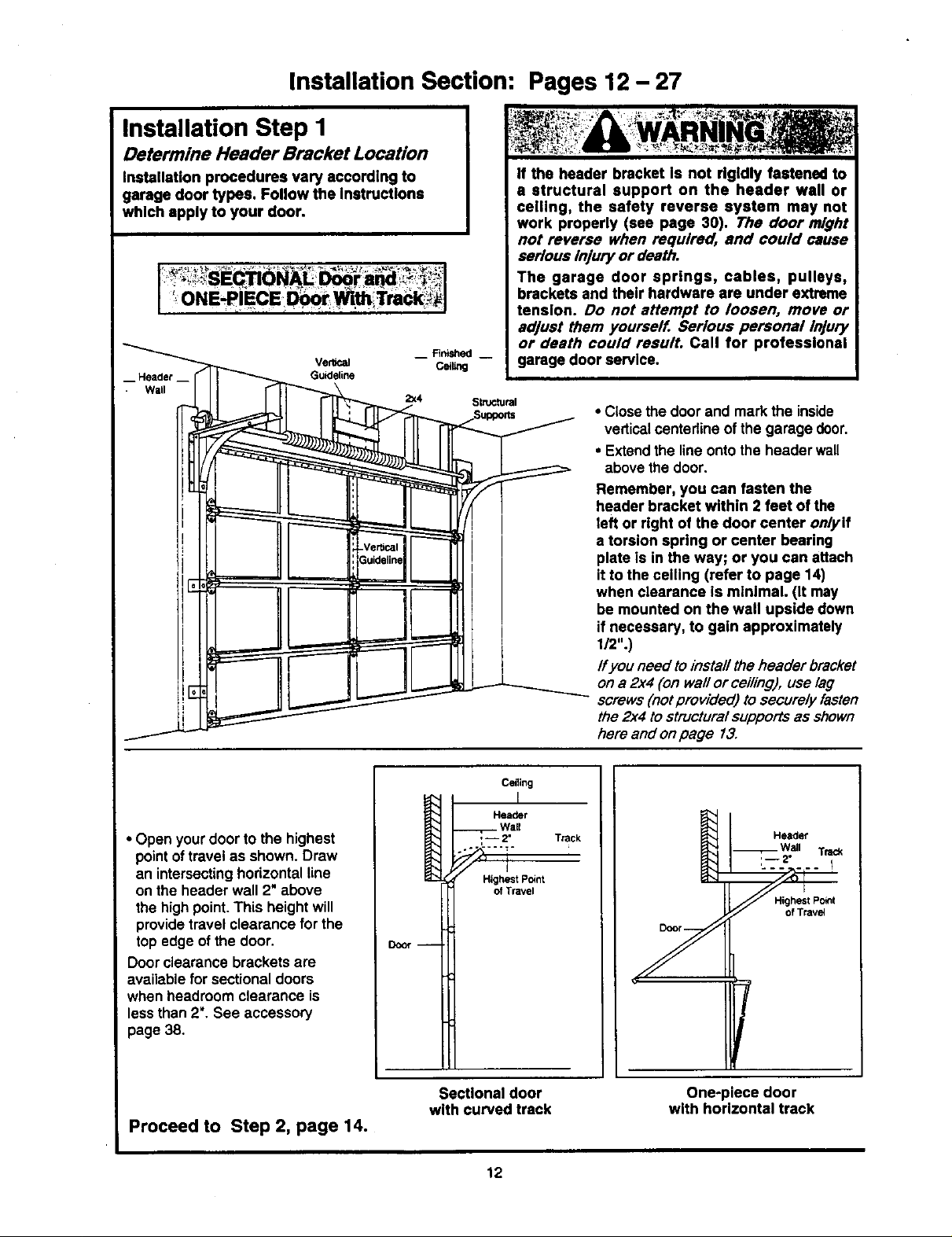
Installation Step I
Determine Header Bracket Location
Installation procedures vary according to
garage door types. Follow the Instructions
which apply to your door.
Ver_cei
-- Header __
Wall
Guideline
2:<4 Structural
J
i Rnished --
cei_g
If the header bracket Is not rigidly fastened to
a structural support on the header wall or
ceiling, the safety reverse system may not
work properly (see page 30). The door might
not reverse when required, and could cause
serious Injury or death.
The garage door springs, cables, pulleys,
brackets and their hardware are under extreme
tension. Do not attempt to loosen, move or
adjust them yourself. Serious personal Injury
or death could result. Call for professional
garage door service.
• Closethe door and mark the inside
verticalcenterline of the garage door.
• Extendthe line ontothe header wall
above the door.
Remember, you can fasten the
header bracket within 2 feet of the
left or right of the door center on/yif
a torsion spring or center bearing
plate is in the way; or you can attach
it to the ceiling (refer to page 14)
when clearance is mthlmal. (It may
be mounted on the wall upside down
if necessary, to gain approximately
1/2".)
Ifyou need toinstall theheader bracket
on a 2x4 (on wail or ceiling), use lag
screws(notprovided) to securely fasten
the2x4 tostructuralsupportsas shown
here and onpage 13.
• Open your door to the highest
pointof travel as shown. Draw
an intersectinghodzontal line
on the header wall 2"above
the highpoint.This height will
providetravel clearance for the
top edge ofthe door.
Doorclearance brackets are
availablefor sectionaldoors
when headroom clearance is
lessthan 2". See accessory
page 38,
Proceed to Step 2, page 14.
Door --
Sectional door
with curved track
Ceiling
Header
Wall
,,-- 2" Track
Highest POint
of Travel
12
Header
Wall Tr_c_
:--2"
Highest Point
of Trave_
One-piece door
with horizontal track
 Loading...