

Craftsman 13953966SRT1 Owner’s Manual
Owner's Manual/lVlanual Del Propietario
ICRRFTSMRN°I
1/2 HP
GARAGE DOOR OPENER
ABRIDOR DE PUERTA DE COCHERA
For Residential Use Only/S61o para uso residencial
Models/Modelos • 139.53962SRT1. 139.53966SRT1 = 139.53959SRT
m
z
C)
F
m
CAUTION:
Read and follow all safety rules
and operating instructions before
first use of this product.
Fasten the manual near the garage
door after installation.
Z
m
o_
Z_
O
F"
PRECAUCION:
Leer y seguir todas las reglas de
seguridad y las instrucciones de
operaci6n antes de usar este
producto pot primera vez.
Guardar este manual cerca de la
puerta del garaje.
00.s
Sears, Roebuck and Co., Hoffman Estates, IL 60179 U.S.A
www.sears, com/oraftsman
TABLE OF CONTENTS
Introduction 2-7
Safety symbol and signal word review ........................ 2
Preparing your garage door ........................................ 3
Tools needed ............................................................... 3
Planning .................................................................. 4-5
Carton inventory .......................................................... 6
Hardware inventory ..................................................... 7
Assembly 8-11
Assemble the rail and install trolley ............................. 8
Fasten rail to motor unit and install idler pulley .......... 9
Install chain/cable and attach sprocket cover ........... 10
Tighten the chain ....................................................... 11
Installation 11-27
Installation safety instructions .................................... 11
Determine the header bracket location ................ 12-13
Install the header bracket .......................................... 14
Attach the rail to the header bracket ......................... 15
Position the opener ................................................... 16
Hang the opener ....................................................... 17
Install the door control ............................................... 18
Install the lights and lens ........................................... 19
Attach the emergency release rope and handle ....... 19
Electrical requirements .............................................. 20
Install the safety reversing sensor ....................... 21-23
Fasten the door bracket ....................................... 24-25
Connect the door arm to the trolley ..................... 26-27
Adjustment 28-30
Adjust the travel limits ............................................... 28
Adjust the force ......................................................... 29
Test the safety reversal system ................................. 30
Test the safety reversing sensor ............................... 30
Operation 31-34
Operation safety instructions ..................................... 31
Using your garage door opener ................................ 31
Using the wall-mounted Door Control ....................... 32
To open the door manually ........................................ 32
Care of your garage door opener .............................. 33
Having a problem? .................................................... 34
Programming 35-36
To add a hand-held remote control ........................... 35
To erase all codes ..................................................... 35
3-Function Remotes .................................................. 35
To add or change a Keyless Entry PIN..................... 36
Repair Parts 37-38
Rail assembly parts ................................................... 37
Installation parts ........................................................ 37
Motor unit assembly parts ......................................... 38
Accessories 39
Warranty 39
Service Numbers Back cover
iNTRODUCTiON
Safety Symbol
and Signal Word Review
This garage door opener has been designed and tested to offer safe service provided it is installed, operated,
maintained and tested in strict accordance with the instructions and warnings contained in this manual.
When you see these Safety Symbols and Signal
Words on the following pages, they will alert you to
Mechanical
Electrical
the possibility of serious injury or death if you do
not comply with the warnings that accompany them.
The hazard may come from something mechanical
or from electric shock. Read the warnings carefully.
When you see this Signal Word on the following
pages, it will alert you to the possibility of damage to
your garage door and/or the garage door opener if
you do not comply with the cautionary statements
that accompany it. Read them carefully.
Preparing your garage door
Before you begin:
• Disable locks.
• Remove any ropes connected to garage door.
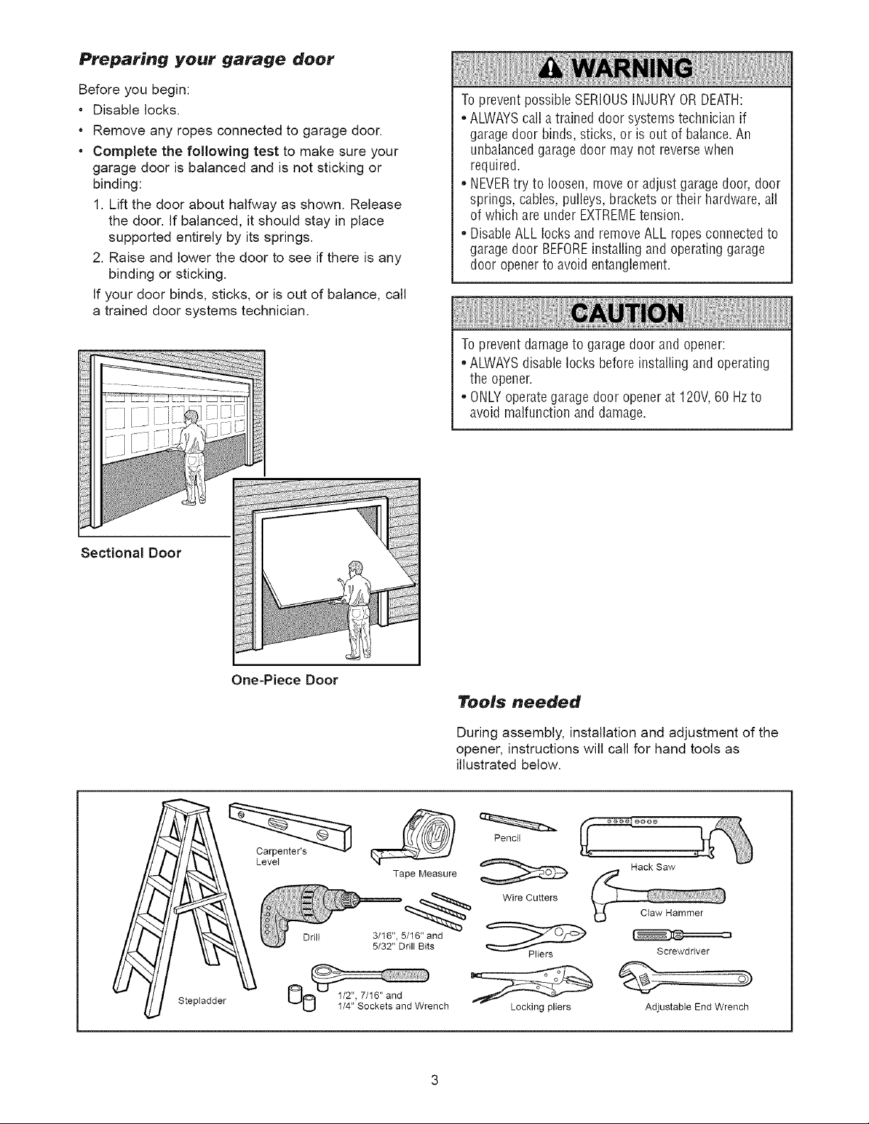
• Complete the following test to make sure your
garage door is balanced and is not sticking or
binding:
1. Lift the door about halfway as shown. Release
the door. If balanced, it should stay in place
supported entirely by its springs.
2. Raise and lower the door to see if there is any
binding or sticking.
If your door binds, sticks, or is out of balance, call
a trained door systems technician.
Topreventpossible SERIOUSINJURYOR DEATH:
• ALWAYScall a trained door systemstechnician if
garagedoor binds, sticks, or is out of balance.An
unbalancedgaragedoor may not reversewhen
required.
• NEVERtry to loosen, move or adjust garagedoor, door
springs, cables,pulleys, brackets or their hardware,all
of which are under EXTREMEtension.
• DisableALL locks and removeALL ropes connected to
garagedoor BEFOREinstalling and operating garage
door opener to avoid entanglement.
Toprevent damageto garage door and opener:
• ALWAYSdisablelocks beforeinstalling and operating
the opener.
• ONLYoperategarage door opener at 120V,60 Hzto
avoid malfunction and damage.
Sectional Door
One=Piece Door
LeveI
Drill
Tape Measure
3/16", 5/16" and
5/32" Drill Bits
Tools needed
During assembly, installation and adjustment of the
opener, instructions will call for hand tools as
illustrated below.
Pencit
Hack Saw
Wire Cutters
Screwdriver
Stepladder
Locking pliers
Adjustable End Wrench
Planning
Identify the type and height of your garage door.
Survey your garage area to see if any of the
conditions below apply to your installation. Additional
materials may be required. You may find it helpful to
refer back to this page and the accompanying
illustrations as you proceed with the installation of
your opener.
Depending on your requirements, there are several
installation steps which may call for materials or
hardware not included in the carton.
• Installation Step 1 - Look at the wall or ceiling
above the garage door. The header bracket must
be securely fastened to structural supports.
• Installation Step 5 - Do you have a finished ceiling
in your garage? If so, a support bracket and
additional fastening hardware may be required.
• Installation Step 10- Depending upon garage
construction, extension brackets or wood blocks
may be needed to install sensors.
• Installation Step 10 -Alternate floor mounting of
the safety reversing sensor will require hardware
not provided.
Do you have an access door in addition to the
garage door? If not, Model 53702 Emergency Key
Release is required. See Accessories page.
Look at the garage door where it meets the floor.
Any gap between the floor and the bottom of the
door must not exceed 1/4". Otherwise, the safety
reversal system may not work properly. See
Adjustment Step 3. Floor or door should be
repaired.
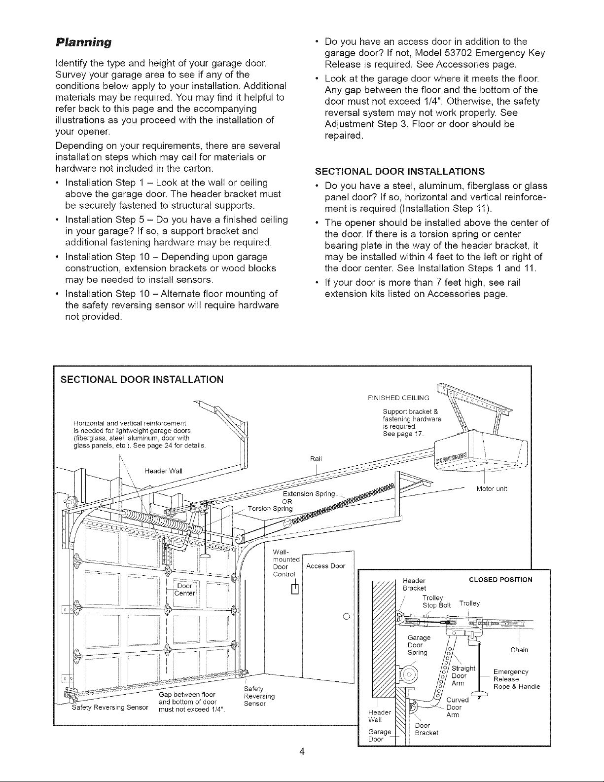
SECTIONAL DOOR iNSTALLATiONS
* Do you have a steel, aluminum, fiberglass or glass
panel door? If so, horizontal and vertical reinforce-
ment is required (installation Step 11).
* The opener should be installed above the center of
the door. If there is a torsion spring or center
bearing plate in the way of the header bracket, it
may be installed within 4 feet to the left or right of
the door center. See Installation Steps 1 and 11.
* If your door is more than 7 feet high, see rail
extension kits listed on Accessories page.
SECTIONAL DOOR iNSTALLATiON
Horizontal and vertical reinforcement
is needed for lightweight garage doors
(fiberglass, steel, aluminum, door with
glass paneIs, etc.). See page 24 for details
Header Wall
Torsion Spring
OR
Waif
mounted
Door
Control
Extension Spring-
Access Door
D
O
FINISHED CEILING
Support bracket &
fastening hardware
is required
See page 17.
Motor unit
Safety Reversing Sensor
Gap between floor
and bottom of door
must not exceed 1/4"
i
Safety
Reversing
Sensor
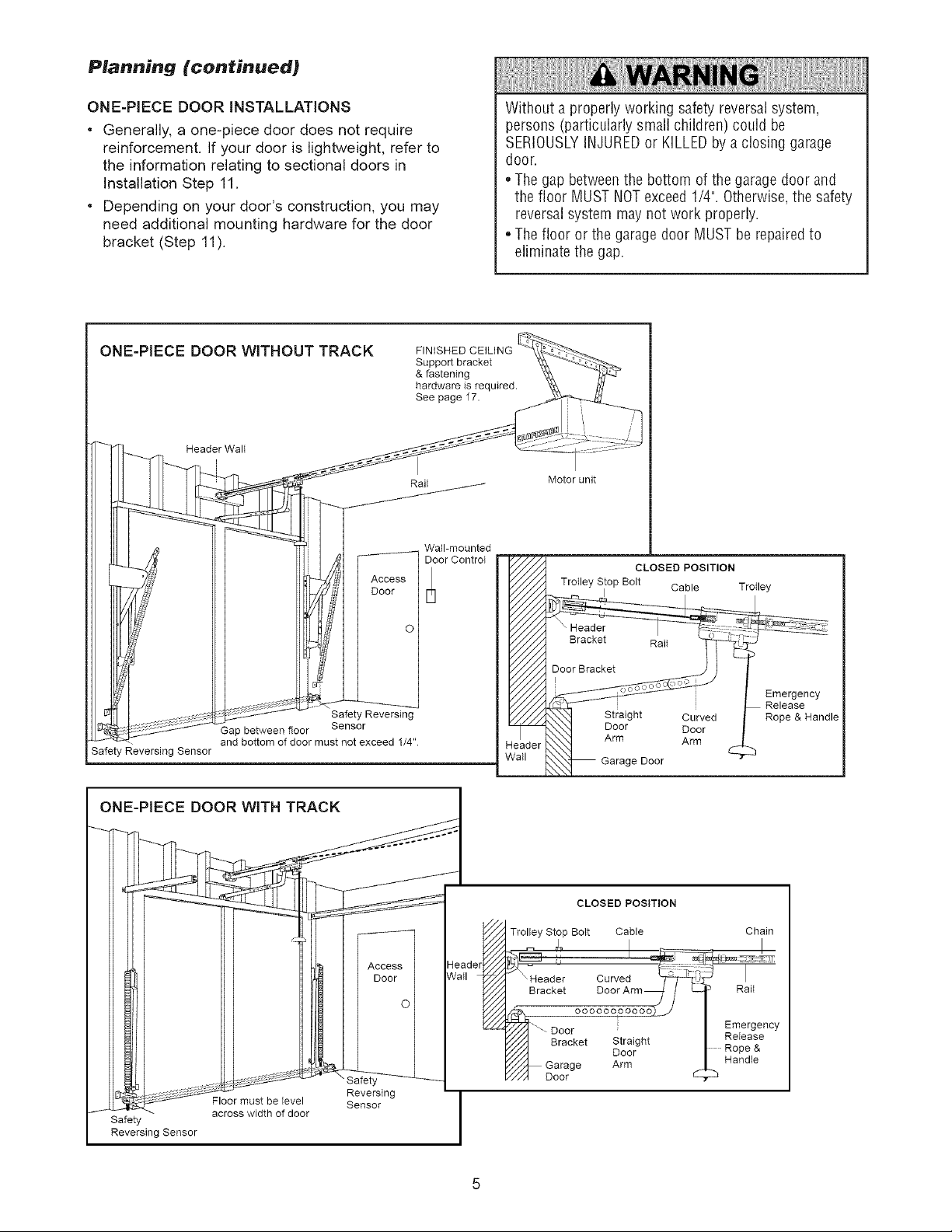
Planning (continued)
ONE-PIECE DOOR INSTALLATIONS
* Generally, a one-piece door does not require
reinforcement. If your door is lightweight, refer to
the information relating to sectional doors in
Installation Step 11.
Depending on your door's construction, you may
need additional mounting hardware for the door
bracket (Step 11).
ONE-PIECE DOOR WITHOUT TRACK
Header Wall
J
Access
Door
FINISHED CEILING
Support bracket
& fastening
hardware is required.
See page 17.
Rai_
Wall-mounted
Door Control
Without a properly working safety reversal system,
persons (particularly small children) could be
SERIOUSLYINJUREDor KILLEDby a closing garage
door.
• Thegap betweenthe bottom of the garage door and
the floor MUST NOTexceed1/4". Otherwise,the safety
reversal system may not work properly.
• Thefloor or the garage door MUST be repairedto
eliminate the gap.
Motor unit
CLOSED POSITION
Trolley Stop Bolt Cable
I
Trolley
Safety Reversing
Safety Reversing Sensor
Gap between floor Sensor
and bottom of door must not exceed 1/4"
_o
dead
I__ , , , Reversing I
__st be level Sensor _ [
/ SafetY--_v across width of door I
Revers ng Sensor |
Bracket Rait
Door Bracket
Emergency
Chain
Rait
Emergency
Release
Rope &
Handte
Release
Rope & Handle
Curved
Door
eader
/all
I
CLOSED POSITION
Trolley Stop Bolt Cable
Header Curved "_T_-'_
Bracket aoorArm_ / L_
ooooooooooo) j"_- Door
y///_ Bracket Straight
_/_, Garage Arm
///4 Door
I
e Door
Door
Arm
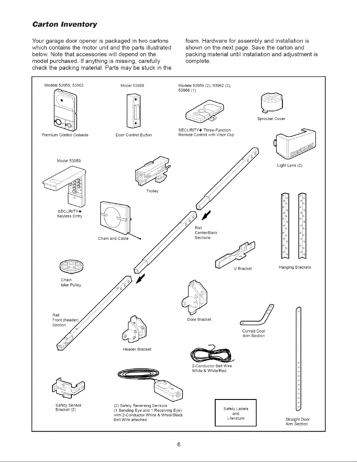
Carton Inventory
Your garage door opener is packaged in two cartons
which contains the motor unit and the parts illustrated
below. Note that accessories will depend on the
model purchased. If anything is missing, carefully
check the packing material. Parts may be stuck in the
Models 53959 53962
Premium Control Console
ModeI 53959
SECURITY+ _ _ ,_
Mode153966 Models 53959 (2), 53962 (2),
Door Control Button
Trolley
foam. Hardware for assembly and installation is
shown on the next page. Save the carton and
packing material until installation and adjustment is
complete.
53966 (1)
SECURITY+ Three-Function
Remote Control with Visor Clip
Light Lens (2)
Keyless Entry _l ._/'_ Rail's"
/_ / Center/Back
Chain and Cable "'_ /f/ Sections
FRaolnt(head er)///_/ _ ,,._/
Section/_ _ _N} _r
_/ _ _ Arm Section
Header Bracket
2-Conductor Belt Wire
White & White/Red
Hanging Brackets
Safety Sensor
Bracket (2)
(2) Safety Reversing Sensors
(1 Sending Eye and 1 Receiving Eye)
with 2-Conductor White & White/Black
BeII Wire attached
and
Literature
I Safety Labets
Straight Door
Arm Section
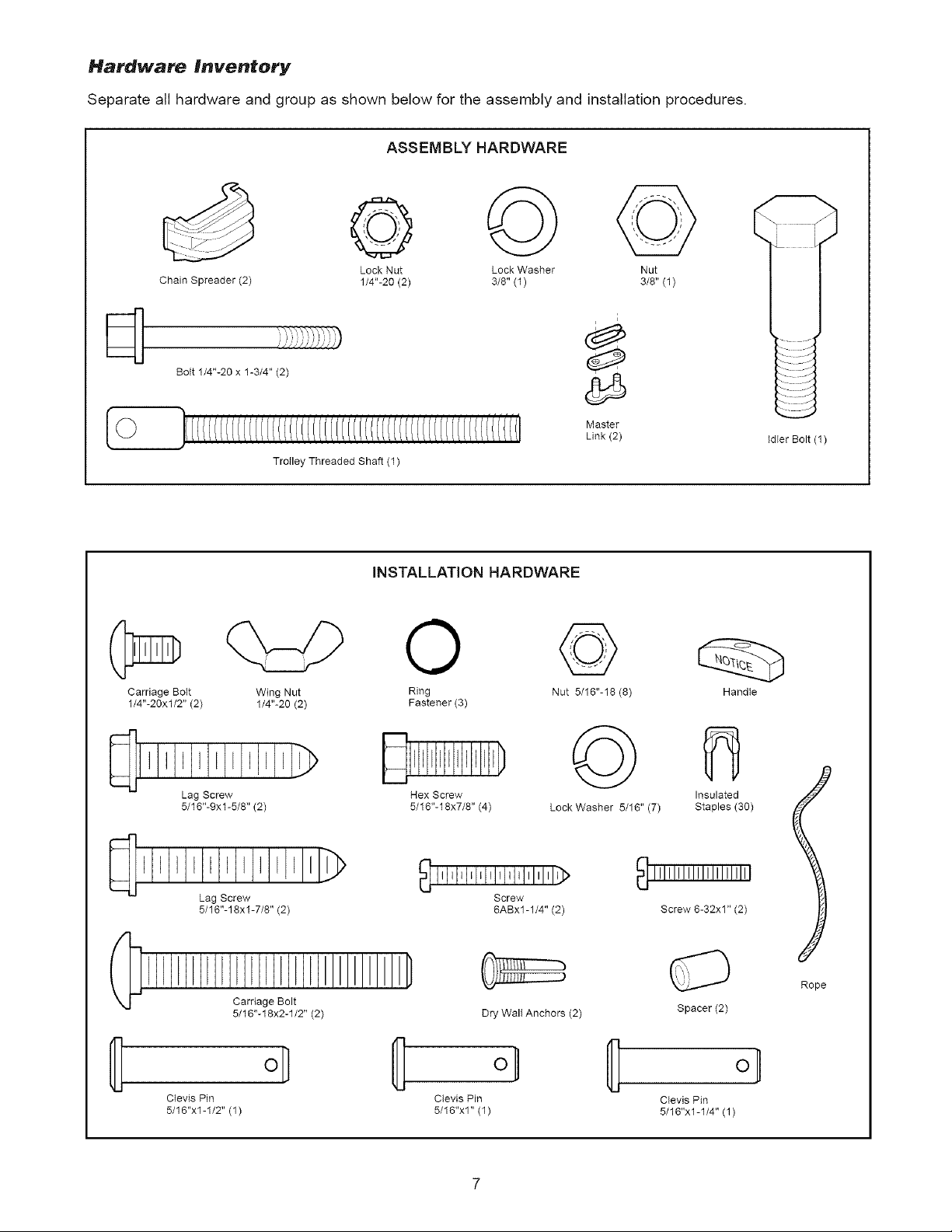
Hardware Inventory
Separate all hardware and group as shown below for the assembly and installation procedures.
ASSEMBLY HARDWARE
©
Chain Spreader (2) 1/4"-20 (2) 3/8" (1) 3/8" (1)
Bolt 1/4"-20 x 1-3/4" (2)
Trotley Threaded Shaft (1)
Carriage Bott
1/4"-20xl/2" (2)
Wing Nut Ring
1/4"-20 (2) Fastener (3)
Lock Nut Lock Washer Nut
Master
Link (2)
iNSTALLATiON HARDWARE
O
©
Nat 5/16"-18 (8)
i
Idler Bolt (1)
Handte
Lag Screw
5/16"-9xl-5/8" (2)
l I I I I I I I I E I I_
Lag Screw
5/16"-18xl-7/8" (2)
Carriage Bolt
5/16"-18x2-1/2" (2)
ol
CIevis Pin
5/16"x1-1/2" (1)
Hex Screw
5/16"-18x7/8" (4)
i,l,l,l,r,r,l,l,J,l,l,l,l>
Screw
6ABx1-1/4" (2)
Dry Walt Anchors (2)
°/
Clevis Pin
5/16"x1" (1)
©
Lock Washer 5/16" (7)
Insulated
Staples (30)
Screw 6-32x1" (2)
Rope
Spacer (2)
CIevis Pin
5/16"x1-1/4" (1)
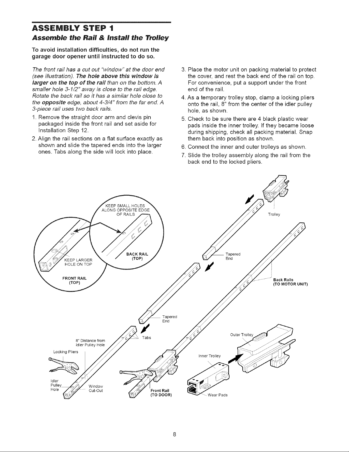
ASSEMBLY STEP t
Assemble the Rail & Install the Trolley
To avoid installation difficulties, do not run the
garage door opener until instructed to do so.
The front rail has a cut out "window" at the door end
(see illustration). The hole above this window is
larger on the top of the rail than on the bottom. A
smafler hole 3-1/2" away is close to the rail edge.
Rotate the back rail so it has a similar hole close to
the opposite edge, about 4-3/4" from the far end. A
3-piece rail uses two back rails.
1. Remove the straight door arm and clevis pin
packaged inside the front rail and set aside for
Installation Step 12.
2. Align the rail sections on a flat surface exactly as
shown and slide the tapered ends into the larger
ones. Tabs along the side will lock into place.
3. Place the motor unit on packing material to protect
the cover, and rest the back end of the rail on top.
For convenience, put a support under the front
end of the rail.
4. As a temporary trolley stop, clamp a locking pliers
onto the rail, 8" from the center of the idler pulley
hole, as shown.
5. Check to be sure there are 4 black plastic wear
pads inside the inner trolley. If they became loose
during shipping, check all packing material. Snap
them back into position as shown.
6. Connect the inner and outer trolleys as shown.
7. Slide the trolley assembly along the rail from the
back end to the locked pliers.
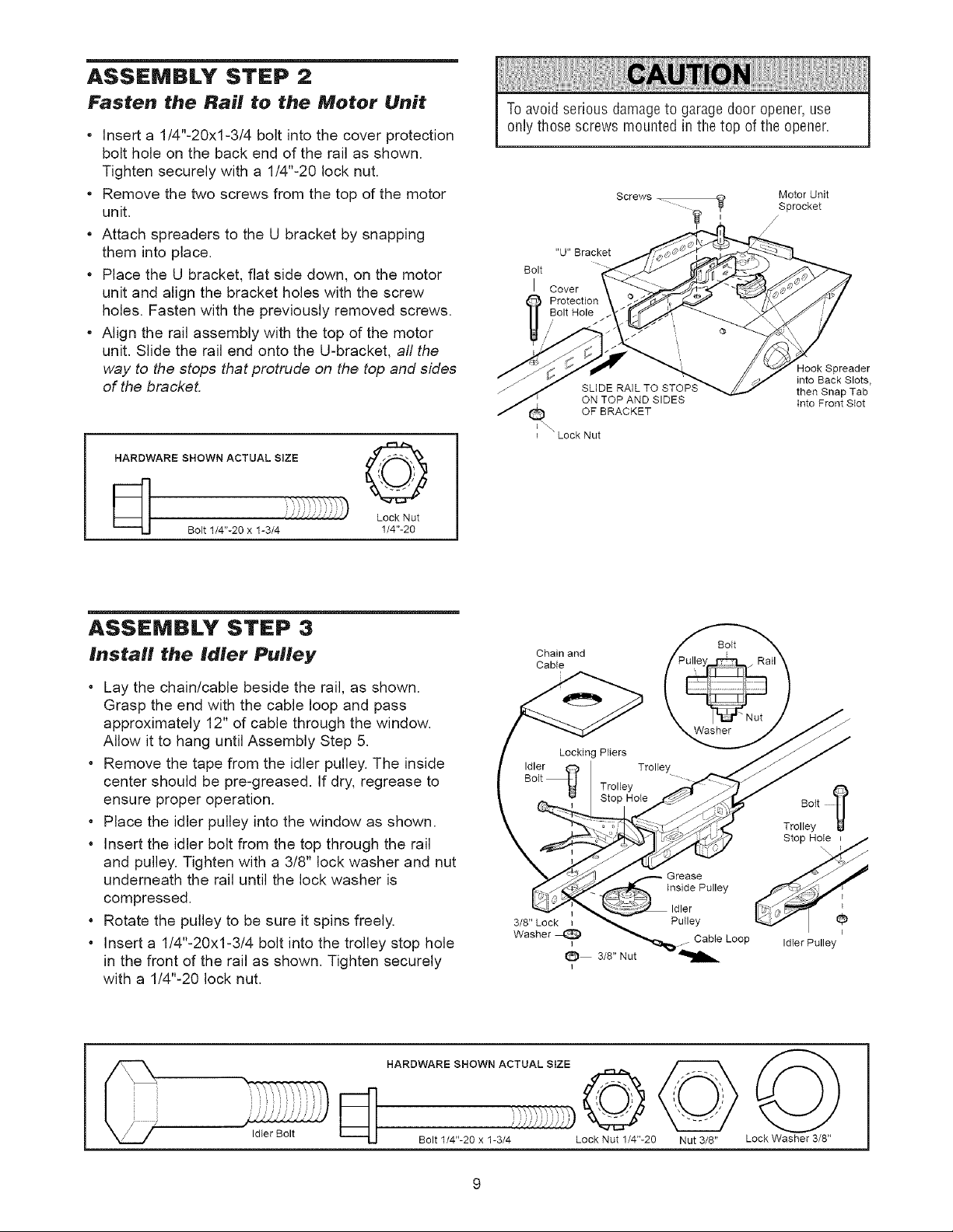
ASSEMBLY STEP 2
Fasten the Rail to the Motor Unit
* Insert a 1/4"-20xl-3/4 bolt into the cover protection
bolt hole on the back end of the rail as shown.
Tighten securely with a 1/4"-20 lock nut.
* Remove the two screws from the top of the motor
unit.
Attach spreaders to the U bracket by snapping
them into place.
Place the U bracket, flat side down, on the motor
unit and align the bracket holes with the screw
holes. Fasten with the previously removed screws.
Align the rail assembly with the top of the motor
unit. Slide the rail end onto the U-bracket, all the
way to the stops that protrude on the top and sides
of the bracket.
HARDWARE SHOWN ACTUAL SiZE ,_Z _,_.1
Toavoid serious damageto garage door opener,use
only those screws mounted in the top of the opener.
Screws
Motor Unit
Sprocket
/
"U" Bracket
Bolt
I Cover
took Spreader
SLIDE RAIL TO STOPS
ON TOP AND SIDES
OF BRACKET
I "Lock Nut
into Back Slots,
then Snap Tab
Into Front SIot
_[_ Lock Nut
Bott 1/4"-20 x 1-3/4 1/4"-20
ASSEMBLY STEP 3
Install the Idler Pulley
Lay the chain/cable beside the rail, as shown.
Grasp the end with the cable loop and pass
approximately 12" of cable through the window.
Allow it to hang until Assembly Step 5.
Remove the tape from the idler pulley. The inside
center should be pre-greased. If dry, regrease to
ensure proper operation.
Place the idler pulley into the window as shown.
Insert the idler bolt from the top through the rail
and pulley. Tighten with a 3/8" lock washer and nut
underneath the rail until the lock washer is
compressed.
Rotate the pulley to be sure it spins freely.
Insert a 1/4"-20xl-3/4 bolt into the trolley stop hole
in the front of the rail as shown. Tighten securely
with a 1/4"-20 lock nut.
Idter Bolt
HARDWARE SHOWN ACTUAL SIZE
_/JJJ/JJ//i_
Bolt 1/4"-20 x 1-3/4 Lock Nut 1/4"-20 Nut 3/8" Lock Washer 3/8"
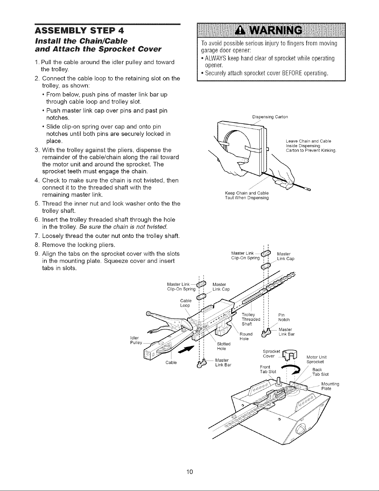
ASSEMBLY STEP 4
Install the Chain/Cable
and Attach the Sprocket Cover
1.Pull the cable around the idler pulley and toward
the trolley.
2. Connect the cable loop to the retaining slot on the
trolley, as shown:
From below, push pins of master link bar up
through cable loop and trolley slot.
Push master link cap over pins and past pin
notches.
Slide clip-on spring over cap and onto pin
notches until both pins are securely locked in
place.
3. With the trolley against the pliers, dispense the
remainder of the cable/chain along the rail toward
the motor unit and around the sprocket. The
sprocket teeth must engage the chain.
4. Check to make sure the chain is not twisted, then
connect it to the threaded shaft with the
remaining master link.
5. Thread the inner nut and lock washer onto the the
trolley shaft.
6. Insert the trolley threaded shaft through the hole
in the trolley. Be sure the chain is not twisted.
7. Loosely thread the outer nut onto the trolley shaft.
8. Remove the locking pliers.
9. Align the tabs on the sprocket cover with the slots
in the mounting plate. Squeeze cover and insert
tabs in slots.
Toavoid possible serious injury to fingers from moving
garage door opener:
• ALWAYSkeephand clear of sprocket while operating
opener.
• Securely attach sprocket cover BEFOREoperating.
Dispensing Carton
. _ Leave Chain and Cable
Keep Chain and Cable
Taut When Dispensing
i i
Master Link Master
Ctip-On Spring Ti .Link Cap
Inside Dispensing
Carton to Prevent Kinking
i
Idler
Cable
Cable
Loop
Master
Link Cap
./-
\
, Slotted
J
, Hole
i
i
_ MasterLink Bar
TroIley Pin
Threaded Notch
Shaft _ Master
Hole
Tab Stot :
Link Bar
Sprocket
Cover
Front
Motor Unit
Sprocket
Back
Tab Stot
j-
" _- Plate
Mounting
10
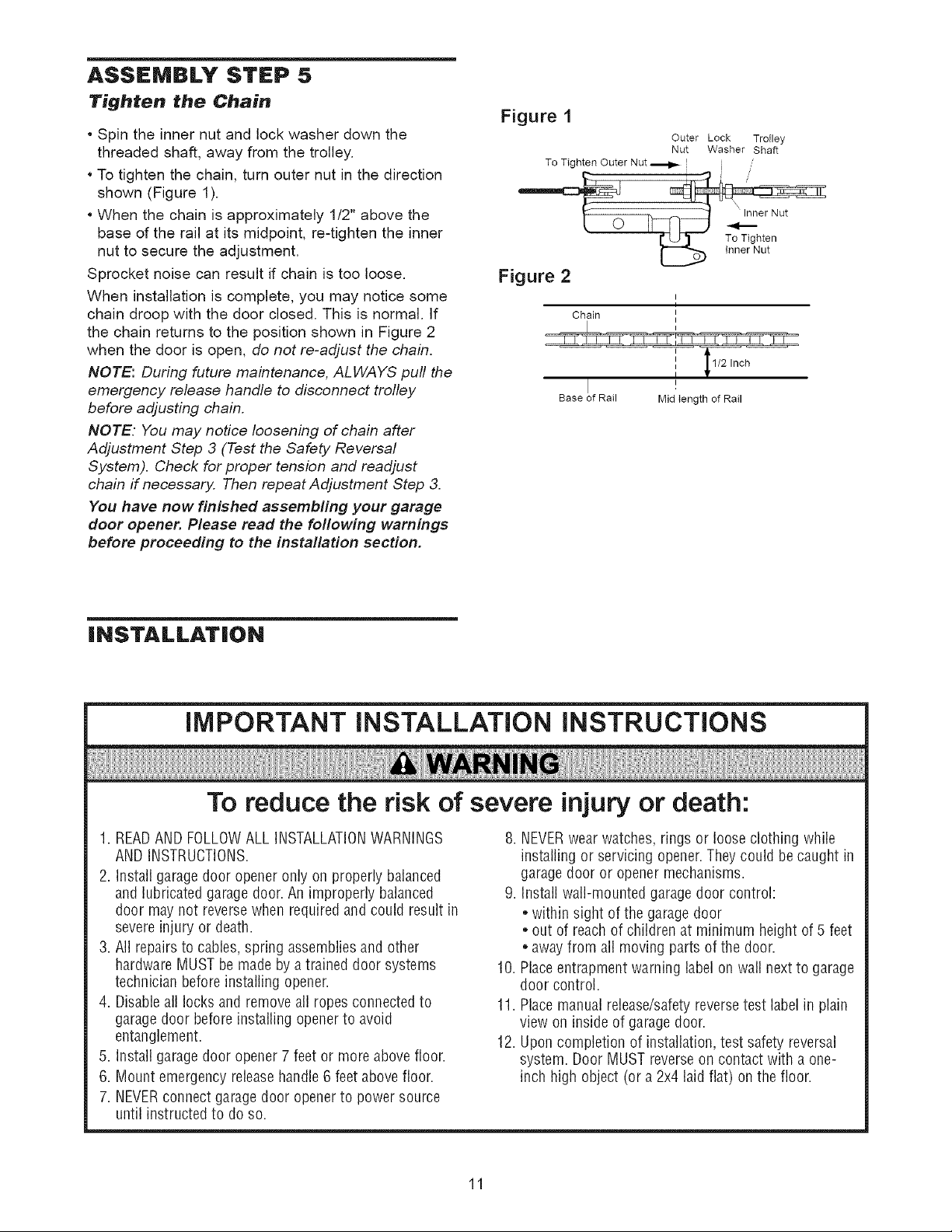
ASSEMBLY STEP 5
Tighten the Chain
• Spin the inner nut and lock washer down the
threaded shaft, away from the trolley.
• To tighten the chain, turn outer nut in the direction
shown (Figure 1).
• When the chain is approximately 1/2" above the
base of the rail at its midpoint, re-tighten the inner
nut to secure the adjustment.
Sprocket noise can result if chain is too loose.
When installation is complete, you may notice some
chain droop with the door closed. This is normal. If
the chain returns to the position shown in Figure 2
when the door is open, do not re-adjust the chain.
NOTE: During future maintenance, ALWAYS pull the
emergency release handle to disconnect trolley
before adjusting chain.
NOTE. You may notice loosening of chain after
Adjustment Step 3 (Test the Safety Reversal
System). Check for proper tension and readjust
chain if necessary. Then repeat Adjustment Step 3.
You have now finished assembling your garage
door opener. Please read the following warnings
before proceeding to the installation section.
Figure 1
To Tighten Outer Nut _ L
Figure 2
Chain I
Base of Rail
Outer Lock Trolley
Nut Washer Shaft
,,
I
Mid tength of Rail
iNSTALLATiON
To reduce the risk of severe injury or death:
1. READAND FOLLOWALL INSTALLATIONWARNINGS
AND INSTRUCTIONS.
2. Install garage door openeronly onproperly balanced
and lubricated garagedoor. An improperly balanced
door may not reversewhen requiredand could result in
severeinjury or death.
3. All repairs to cables,spring assembliesand other
hardware MUSTbe madeby a trained door systems
technician beforeinstalling opener.
4. Disableall locks and removeall ropes connectedto
garagedoor before installing opener to avoid
entanglement.
5. Install garage door opener7 feet or more abovefloor.
6. Mount emergency releasehandle6 feet abovefloor.
7. NEVERconnect garage door openerto power source
until instructedto do so.
8. NEVERwear watches, rings or loose clothing while
installing or servicing opener.They could be caught in
garage door or opener mechanisms.
9. Install wall-mounted garagedoor control:
• within sight of the garage door
• out of reachof children at minimum height of 5 feet
• awayfrom all moving parts of the door.
10. Placeentrapment warning label on wall next to garage
door control.
11. Placemanual release/safetyreversetest label in plain
view on insideof garage door.
12. Upon completion of installation, test safety reversal
system. Door MUST reverseon contact with a one-
inch high object (or a 2x4 laid flat) on the floor.
11
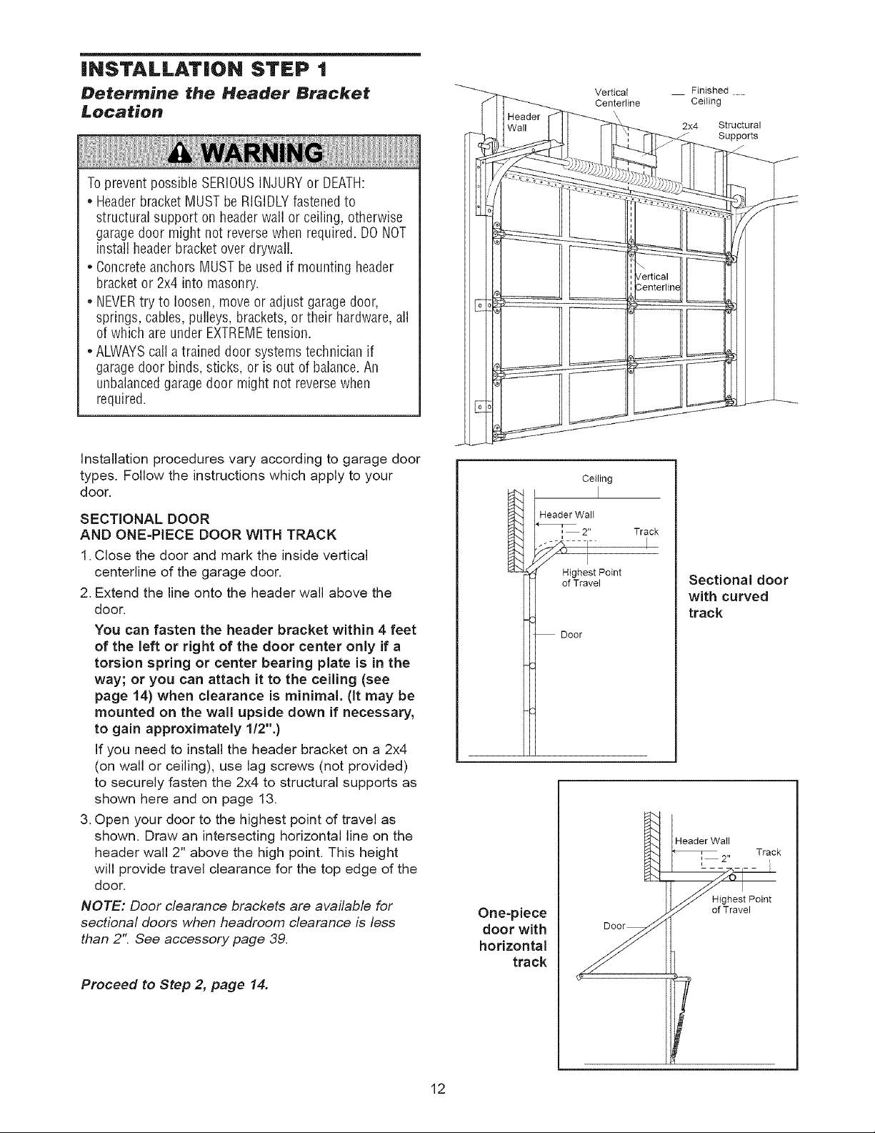
iNSTALLATiON STEP t
Determine the Header Bracket
Location
Toprevent possible SERIOUSINJURYor DEATH:
* Headerbracket MUSTbe RIGIDLYfastenedto
structural support on headerwall or ceiling, otherwise
garage door might not reversewhen required. DONOT
install headerbracket over drywall.
* Concreteanchors MUST be usedif mounting header
bracket or 2x4 into masonry.
NEVERtry to loosen, move or adjust garage door,
springs, cables, pulleys, brackets,or their hardware,all
of which are under EXTREMEtension.
* ALWAYScall a trained door systemstechnician if
garage door binds,sticks, or is out of balance.An
unbalancedgarage door might not reversewhen
required.
Installation procedures vary according to garage door
types. Follow the instructions which apply to your
door.
SECTIONAL DOOR
AND ONE-PIECE DOOR WITH TRACK
1.Close the door and mark the inside vertical
centerline of the garage door.
2. Extend the line onto the header wall above the
door.
You can fasten the header bracket within 4 feet
of the left or right of the door center only if a
torsion spring or center bearing plate is in the
way; or you can attach it to the ceiling (see
page 14) when clearance is minimal. (It may be
mounted on the wall upside down if necessary,
to gain approximately 1/2".)
If you need to install the header bracket on a 2x4
(on wall or ceiling), use lag screws (not provided)
to securely fasten the 2x4 to structural supports as
shown here and on page 13.
3. Open your door to the highest point of travel as
shown. Draw an intersecting horizontal line on the
header wall 2" above the high point. This height
will provide travel clearance for the top edge of the
door.
NOTE: Door clearance brackets are available for
sectional doors when headroom clearance is less
than 2". See accessory page 39.
One-piece
door with
horizontal
track
Vertical
Centerline
Ceiling
Header WalI
= 2"
=
_" /{I
_High st Point
of Travel
Door
Finished
Ceiting
2x4 Structural
Track
I
Sectional door
with curved
track
i Header War I
_, 2" Track
II ghest Peiot
Supports
j-
Proceed to Step 2, page 14.
!
12
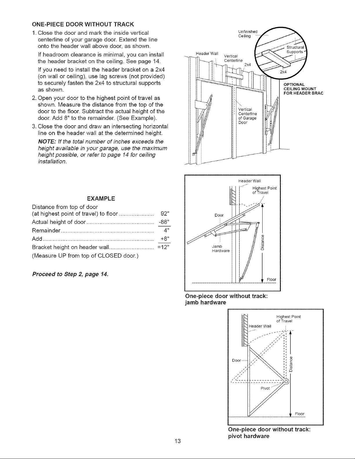
ONE-PIECE DOOR WITHOUT TRACK
1.Close the door and mark the inside vertical
centerline of your garage door. Extend the line
onto the header wall above door, as shown.
If headroom clearance is minimal, you can install
the header bracket on the ceiling. See page 14.
If you need to install the header bracket on a 2x4
(on wall or ceiling), use lag screws (not provided)
to securely fasten the 2x4 to structural supports
as shown.
2. Open your door to the highest point of travel as
shown. Measure the distance from the top of the
door to the floor. Subtract the actual height of the
door. Add 8" to the remainder. (See Example).
3. Close the door and draw an intersecting horizontal
line on the header wall at the determined height.
NOTE: If the total number of inches exceeds the
height available in your garage, use the maximum
height possible, or refer to page 14 for ceiling
installation.
EXAMPLE
Distance from top of door
(at highest point of travel) to floor ...................... 92"
Actual height of door .......................................... -88"
Remainder .......................................................... 4"
Add ..................................................................... +8"
Bracket height on header wall ............................ =12"
(Measure UP from top of CLOSED door.)
Header Walt
Jamb
Door
Hardware
Vertical
Centerline
i 2x4
Unfinished
Ceiling
Header Walt
jJ
Highest Point
of Travet
CEILING MOUNT
FOR HEADER BRAC
Proceed to Step 2, page 14.
One-piece door without track:
jamb hardware
Door
One-piece door without track:
13
pivot hardware
Highest Point
of Travel
Header Wall i
J / / i I
Ii
Ii
Ii o)
C3
Floor
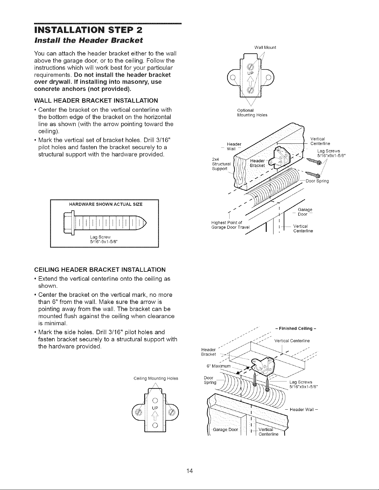
iNSTALLATiON STEP 2
Install the Header Bracket
You can attach the header bracket either to the wall
above the garage door, or to the ceiling. Follow the
instructions which will work best for your particular
requirements. Do not install the header bracket
over drywall, if installing into masonry, use
concrete anchors (not provided).
WALL HEADER BRACKET INSTALLATION
* Center the bracket on the vertical centerline with
the bottom edge of the bracket on the horizontal
line as shown (with the arrow pointing toward the
ceiling).
* Mark the vertical set of bracket holes. Drill 3/16"
pilot holes and fasten the bracket securely to a
structural support with the hardware provided.
HARDWARE SHOWN ACTUAL SIZE
] J ] I I J I
Lag Screw
5/16"-9xl-5/8"
Optional
Mounting Holes
Header
Wall
2x4
Structural
Support
/
/
/
i
Highest Point of
Garage Door TraveI
/
Wail Mount
Garage
Door
Vertical
Centerline
VerticaI
Centerline
Lag Screws
5/16"x9x1-5/8"
/
CEILING HEADER BRACKET INSTALLATION
* Extend the vertical centerline onto the ceiling as
shown.
, Center the bracket on the vertical mark, no more
than 6" from the wall. Make sure the arrow is
pointing away from the wall. The bracket can be
mounted flush against the ceiling when clearance
is minimal.
, Mark the side holes. Drill 3/16" pilot holes and
fasten bracket securely to a structural support with
the hardware provided.
Ceiling Mounting Holes
/ Vertical Centedine
Header _
Bracket /_
t
/
6" Maximum
Door
Spring Lag Screws
i _'_ - Finished Ceiling -
5/16"x9x1-5/8"
Header Wall
Centedine
14
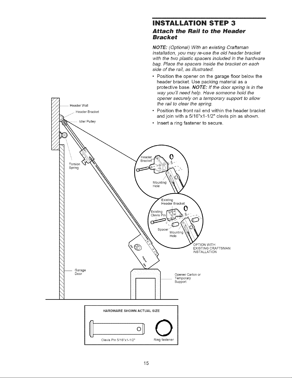
iNSTALLATiON STEP 3
Attach the Rail to the Header
Bracket
NOTE: (Optional) With an existing Craftsman
installation, you may re-use the old header bracket
with the two plastic spacers included in the hardware
bag. Place the spacers inside the bracket on each
side of the rail, as illustrated.
• Position the opener on the garage floor below the
header bracket. Use packing material as a
protective base. NOTE: If the door spring is in the
way you'll need help. Have someone hold the
//
//
//
//
//
//
//
//
//
//
//
Header Bracket
/j J"
Idler Pulley
opener securely on a temporary support to allow
the rail to clear the spring.
• Position the front rail end within the header bracket
and join with a 5/16"x1-1/2" clevis pin as shown.
• Insert a ring fastener to secure.
0
Torsion
Spring
Garage
Door
Mounting
Hole
HARDWARE SHOWN ACTUAL SiZE
/
Header Bracket
Spacer
Mounting
Hole
0
OPTION WiTH
EXISTING CRAFTSMAN
iNSTALLATION
Opener Carton or
Temporary
Support
©
Clevis Pin 5/16"x1-1/2" Ring fastener
15
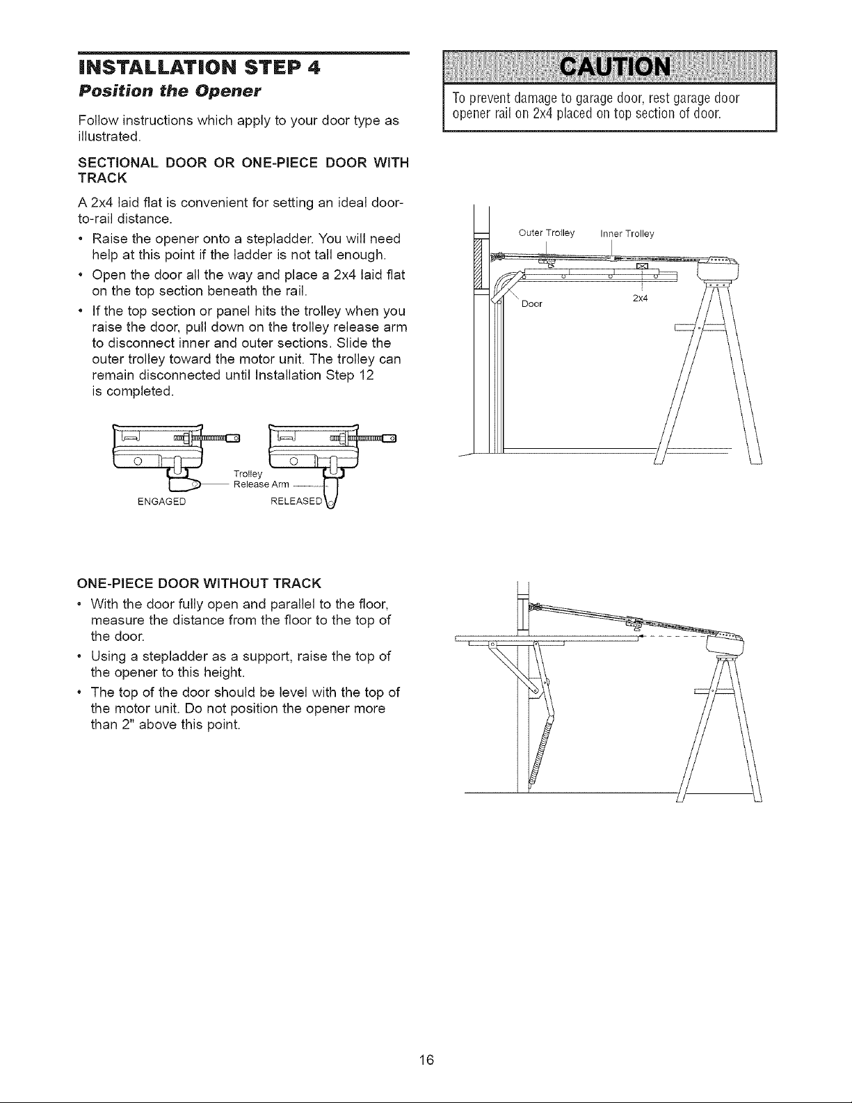
|NSTALLAT|ON STEP 4
Position the Opener
Follow instructions which apply to your door type as
illustrated.
SECTIONAL DOOR OR ONE-PIECE DOOR WITH
TRACK
A 2x4 laid flat is convenient for setting an ideal door-
to-rail distance.
* Raise the opener onto a stepladder. You will need
help at this point if the ladder is not tall enough.
Open the door all the way and place a 2x4 laid flat
on the top section beneath the rail.
If the top section or panel hits the trolley when you
raise the door, pull down on the trolley release arm
to disconnect inner and outer sections. Slide the
outer trolley toward the motor unit. The trolley can
remain disconnected until Installation Step 12
is completed.
ottey
elease Arm [ J
ENGAGED RELEASED _/
Toprevent damageto garage door, rest garage door
opener rail on 2x4 placedontop section of door.
Outer Trolley Inner Trolley
Door
2x4
ONE-PIECE DOOR WITHOUT TRACK
* With the door fully open and parallel to the floor,
measure the distance from the floor to the top of
the door.
* Using a stepladder as a support, raise the top of
the opener to this height.
* The top of the door should be level with the top of
the motor unit. De not position the opener more
than 2" above this point.
16
iNSTALLATiON STEP 5
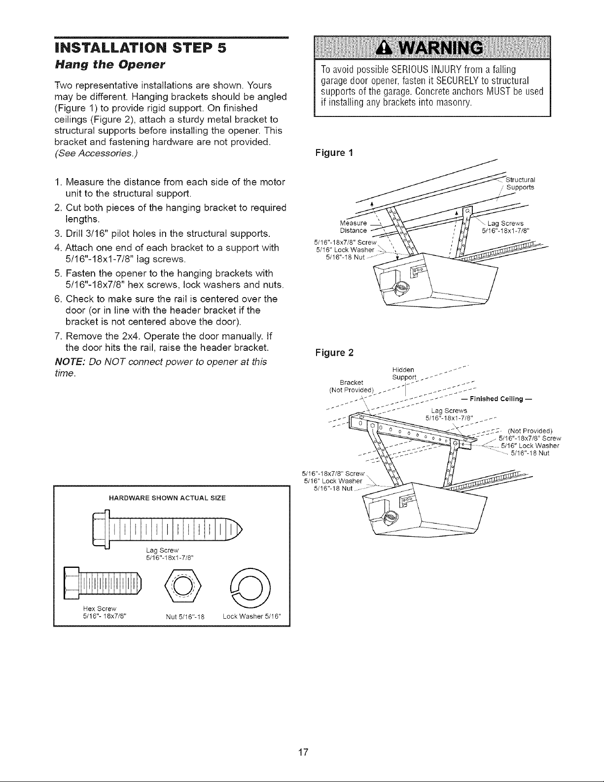
Hang the Opener
Two representative installations are shown. Yours
may be different. Hanging brackets should be angled
(Figure 1) to provide rigid support. On finished
ceilings (Figure 2), attach a sturdy metal bracket to
structural supports before installing the opener. This
bracket and fastening hardware are not provided.
(See Accessories.)
1. Measure the distance from each side of the motor
unit to the structural support.
2. Cut both pieces of the hanging bracket to required
lengths.
3. Drill 3/16" pilot holes in the structural supports.
4. Attach one end of each bracket to a support with
5/16"-18xl-7/8" lag screws.
5. Fasten the opener to the hanging brackets with
5/16"-18x7/8" hex screws, lock washers and nuts.
6. Check to make sure the rail is centered over the
door (or in line with the header bracket if the
bracket is not centered above the door).
7. Remove the 2x4. Operate the door manually. If
the door hits the rail, raise the header bracket.
NOTE: Do NOT connect power to opener at this
time.
Toavoid possible SERIOUSINJURYfrom a falling
garage door opener,fasten it SECURELYto structural
supports of the garage. Concreteanchors MUSTbe used
if installing any brackets into masonry.
Figure 1
Supports
Measure ', Screws
Distance 5/16"-18xl-7/8"
5/16"- 18x7/8" Screw
5/16"
Figure 2
HARDWARE SHOWN ACTUAL SiZE
Lag Screw
5/16"-18xl -7/8"
©
Hex Screw
5/16"- 18x7/8"
Nut 5/16"-18
©
Lock Washer 5/16"
5/16"-18x7/8" Screw
5/16" Lock Washer
5/16"-18 Nut
- 5/16"-18 Nut
17
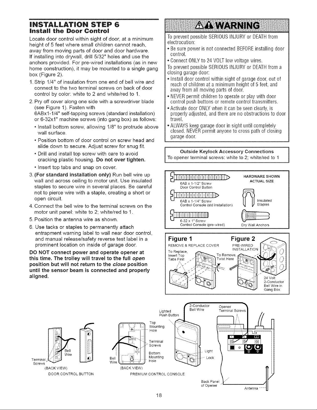
iNSTALLATiON STEP 6
install the Door Contro|
Locate door control within sight of door, at a minimum
height of 5 feet where small children cannot reach,
away from moving parts of door and door hardware.
If installing into drywall, drill 5/32" holes and use the
anchors provided. For pre-wired installations (as in new
home construction), it may be mounted to a single gang
box (Figure 2).
1.Strip 1/4" of insulation from one end of bell wire and
connect to the two terminal screws on back of door
control by color: white to 2 and white/red to 1.
2. Pry off cover along one side with a screwdriver blade
(see Figure 1). Fasten with
6ABxl-1/4" self-tapping screws (standard installation)
or 6-32x1" machine screws (into gang box) as follows:
* Install bottom screw, allowing 1/8" to protrude above
wall surface.
Position bottom of door control on screw head and
slide down to secure. Adjust screw for snug fit.
Drill and install top screw with care to avoid
cracking plastic housing. Do not over tighten,
Insert top tabs and snap on cover.
3.(For standard installation only) Run bell wire up
wall and across ceiling to motor unit. Use insulated
staples to secure wire in several places. Be careful
not to pierce wire with a staple, creating a short or
open circuit.
4. Connect the bell wire to the terminal screws on the
motor unit panel: white to 2; white/red to 1.
5. Position the antenna wire as shown.
6. Use tacks or staples to permanently attach
entrapment warning label to wall near door control,
and manual release/safety reverse test label in a
prominent location on inside of garage door.
DO NOT connect power and operate opener at
this time. The trolley will travel to the full open
position but will not return to the close position
until the sensor beam is connected and properly
aligned.
Toprevent possible SERIOUSINJURYor DEATHfrom
electrocution:
• Be sure power is not connected BEFOREinstalling door
control.
ConnectONLYto 24 VOLTlow voltage wires.
Toprevent possible SERIOUSINJURYor DEATHfrom a
closing garagedoor:
Install doorcontrol within sight of garage door, out of
reachof children at a minimum height of 5 feet, and
awayfrom all moving parts of door.
NEVERpermit children to operate or play with door
control push buttons or remotecontrol transmitters.
Activate door ONLYwhen it can be seen clearly,is
properly adjusted, and there are no obstructions to door
travel.
• ALWAYSkeepgarage door in sight until completely
closed. NEVERpermit anyoneto cross path of closing
garagedoor.
Outside Keylock Accessory Connections |
Toopener terminal screws: white to 2; white/red to 1
_ lllllllllllllllllllllllllllllll]>
6AB x 1-1/2" Screw
Door Controt Button
_111; 'AI; I1 I1'_111/1_,I,slclrle,; , I_j_
Control Consote (std installation)
Control Console (pre-wired)
HARDWARE SHOWN
ACTUAL SIZE
Insulated
Staples
Dry Walt Anchors
Figure 1 Figure 2
REMOVE & REPLACE COVER PRE-WtRED
To Replace,
Insert Top To Remove
Tabs First Twist Here
INSTALLATION
24 Volt
2-Conductor
Bell Wire in
Gang Box
1
Top
_,_,,__( J - F -'_-. TerminaI
_ _ M°lUenting
/_ Wire Bell l /_ 1.1 Mounting
Z_rcrmeinw_l Wire _ _ Hole
(BACK VIEW) (BACK VIEW)
DOOR CONTROL BUTTON PREMIUM CONTROL CONSOLE
i l _ I Bottom
Lighted
Push Button
18
Betl Wire Terminal Screw_
Back Panel
of Opener
Opener
Light
Lock
Antenna
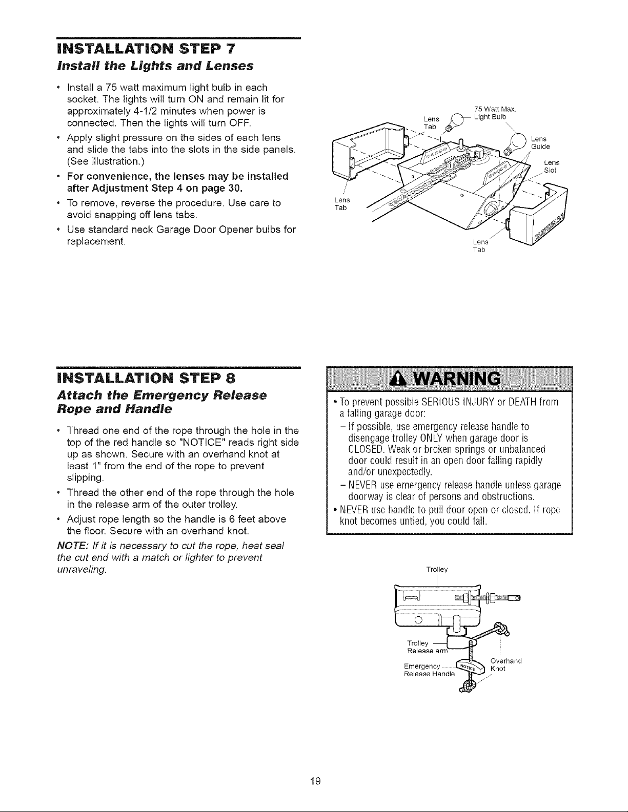
iNSTALLATiON STEP 7
Install the Lights and Lenses
• Install a 75 watt maximum light bulb in each
socket. The lights will turn ON and remain Ntfor
approximately 4-1/2 minutes when power is
connected. Then the lights will turn OFF.
• Apply slight pressure on the sides of each lens
and slide the tabs into the slots in the side panels.
(See illustration.)
• For convenience, the lenses may be installed
after Adjustment Step 4 on page 30.
• To remove, reverse the procedure. Use care to
avoid snapping off lens tabs.
• Use standard neck Garage Door Opener bulbs for
replacement.
Lens
Tab
75 Watt Max
Lens _ Light Bulb
Sabie S
Lens j
Tab
Lens
Guide
Lens
Slot
INSTALLATION STEP 8
Attach the Emergency Release
Rope and Handle
• Thread one end of the rope through the hole in the
top of the red handle so "NOTICE" reads right side
up as shown. Secure with an overhand knot at
least 1" from the end of the rope to prevent
slipping.
• Thread the other end of the rope through the hole
in the release arm of the outer trolley.
• Adjust rope length so the handle is 6 feet above
the floor. Secure with an overhand knot.
NOTE: ff it is necessary to cut the rope, heat seal
the cut end with a match or lighter to prevent
unraveling.
• Toprevent possible SERIOUSINJURYor DEATHfrom
a falling garagedoor:
- If possible, useemergency releasehandleto
disengagetrolley ONLYwhengarage door is
CLOSED.Weakor broken springs or unbalanced
door could result in an open door falling rapidly
and/or unexpectedly.
- NEVERuseemergency releasehandle unless garage
doorway is clear of persons and obstructions.
• NEVERusehandleto pull door open or closed. If rope
knot becomes untied, you could fall.
Trolley
Trolley
Emergency Knot
Release Handle
Overhand
19
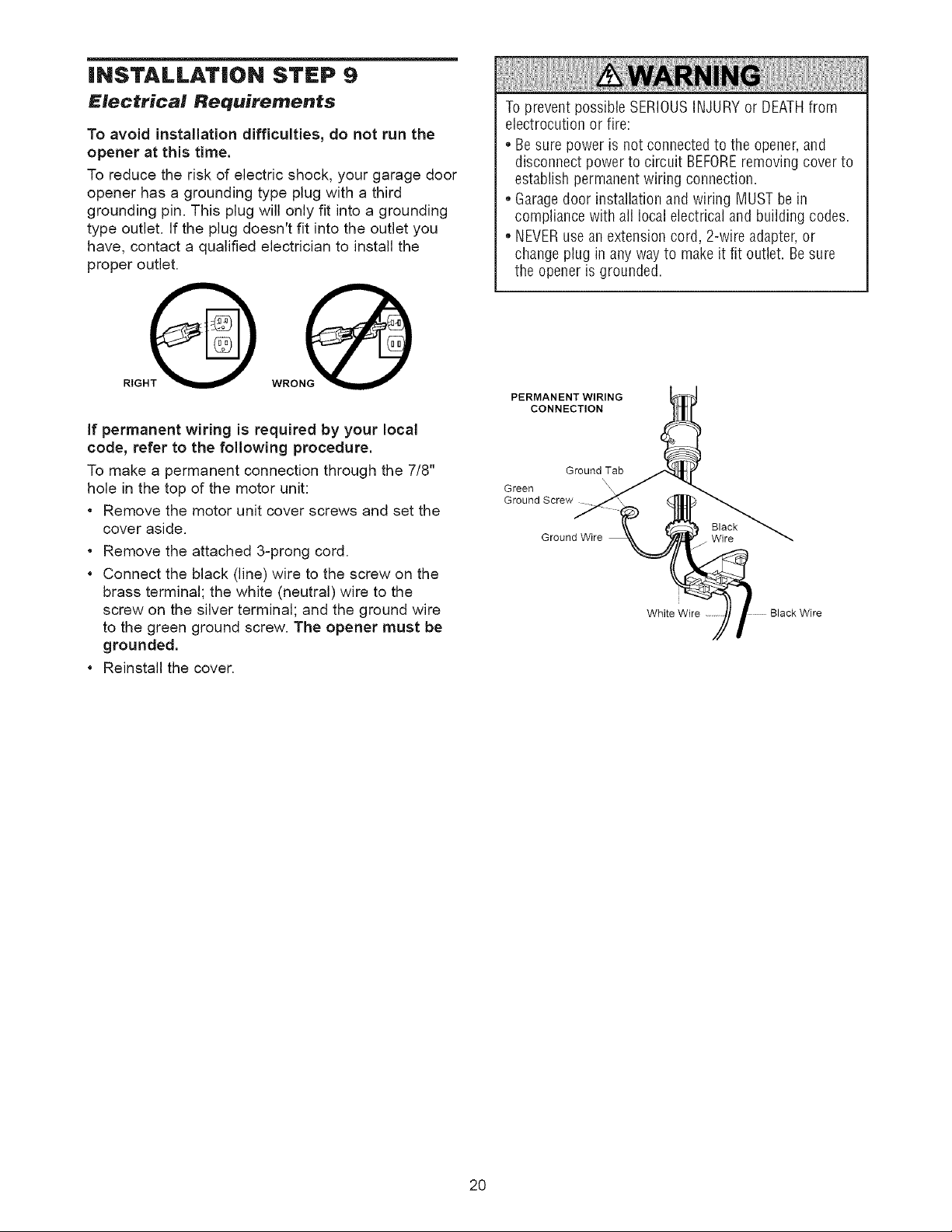
iNSTALLATiON STEP 9
Electrical Requirements
To avoid installation difficulties, do not run the
opener at this time.
To reduce the risk of electric shock, your garage door
opener has a grounding type plug with a third
grounding pin. This plug will only fit into a grounding
type outlet. If the plug doesn't fit into the outlet you
have, contact a qualified electrician to install the
proper outlet.
RIGHO WRONG
if permanent wiring is required by your local
code, refer to the following procedure.
To make a permanent connection through the 7/8"
hole in the top of the motor unit:
Remove the motor unit cover screws and set the
cover aside.
Remove the attached 3-prong cord.
• Connect the black (line) wire to the screw on the
brass terminal; the white (neutral) wire to the
screw on the silver terminal; and the ground wire
to the green ground screw. The opener must be
grounded.
Reinstall the cover.
Toprevent possible SERIOUSINJURYor DEATHfrom
electrocution or fire:
• Be sure power is not connected to the opener,and
disconnect power to circuit BEFOREremoving coverto
establish permanentwiring connection.
• Garagedoor installation and wiring MUSTbe in
compliance with all local electricaland building codes.
NEVERusean extension cord, 2-wire adapter, or
changeplug in any way to makeit fit outlet. Besure
the openeris grounded.
PERMANENT WIRING
CONNECTION
Ground Tab
Green
Ground Screw
Ground Wire Wire
Black
i
Black Wire
20
INSTALLATION STEP 10
Install The Safety Reversing Sensor
The safety reversing sensor must be connected
and aligned correctly before the garage door
opener will move in the down direction.
IMPORTANT INFORMATION ABOUT
THE SAFETY REVERSING SENSOR
When properly connected and aligned, the sensor
will detect an obstacle in the path of its electronic
beam. The sending eye (with an orange indicator
light) transmits an invisible light beam to the
receiving eye (with a green indicator light). If an
obstruction breaks the light beam while the door is
closing, the door will stop and reverse to full open
position, and the opener lights will flash 10 times.
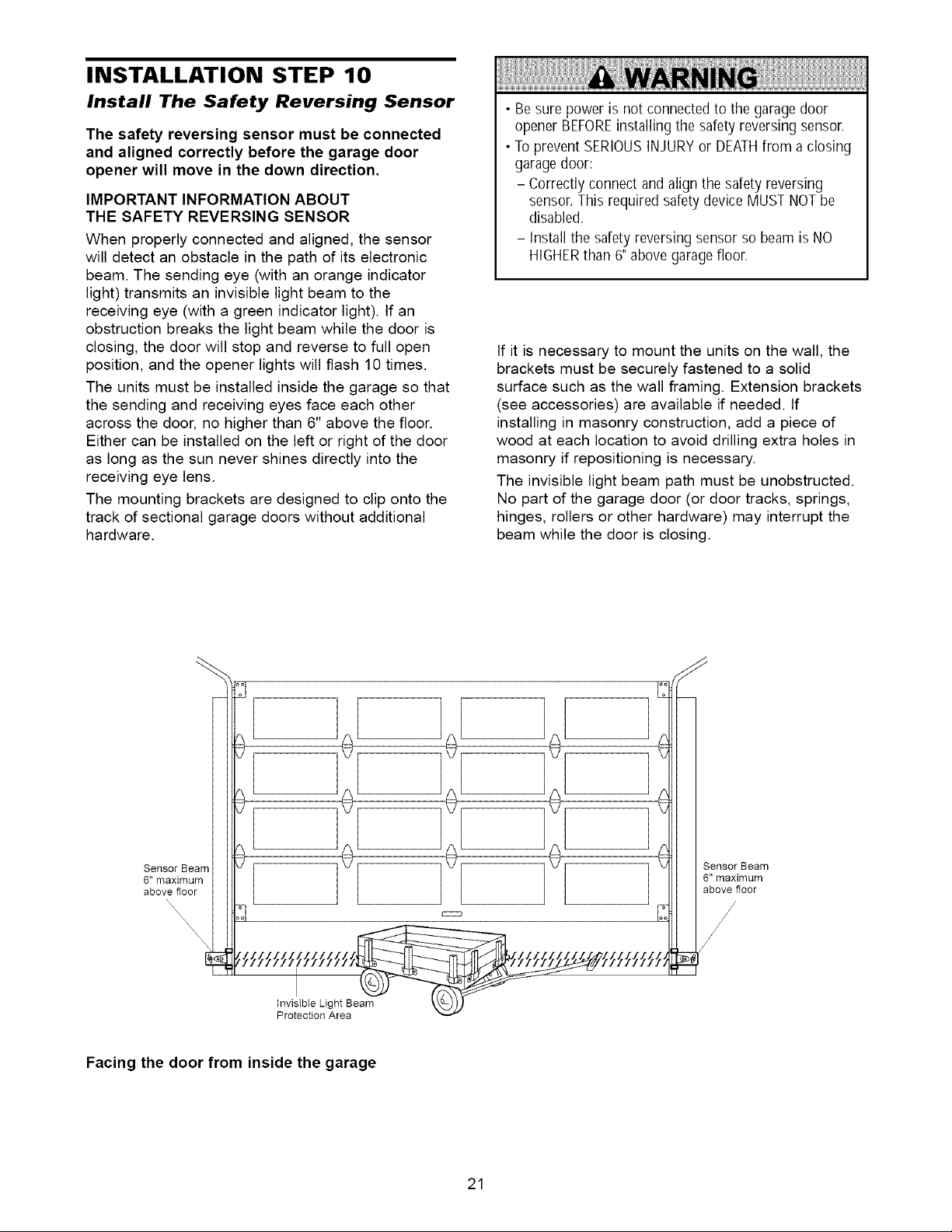
The units must be installed inside the garage so that
the sending and receiving eyes face each other
across the door, no higher than 6" above the floor.
Either can be installed on the left or right of the door
as long as the sun never shines directly into the
receiving eye lens.
The mounting brackets are designed to clip onto the
track of sectional garage doors without additional
hardware.
• Be sure power is not connected to the garage door
opener BEFOREinstalling the safety reversing sensor.
• Toprevent SERIOUSINJURYor DEATHfrom a closing
garagedoor:
- Correctly connect and align the safety reversing
sensor.This required safety device MUST NOTbe
disabled.
- Install the safety reversing sensor so beamis NO
HIGHERthan 6" abovegarage floor.
If it is necessary to mount the units on the wall, the
brackets must be securely fastened to a solid
surface such as the wall framing. Extension brackets
(see accessories) are available if needed. If
installing in masonry construction, add a piece of
wood at each location to avoid drilling extra holes in
masonry if repositioning is necessary.
The invisible light beam path must be unobstructed.
No part of the garage door (or door tracks, springs,
hinges, rollers or other hardware) may interrupt the
beam while the door is closing.
Facing the door from inside the garage
21
INSTALLING THE BRACKETS
Be sure power to the opener is disconnected.
Install and align the brackets so the sensors will face
each other across the garage door, with the beam no
higher than 6" above the floor. They may be installed
in one of three ways, as follows.
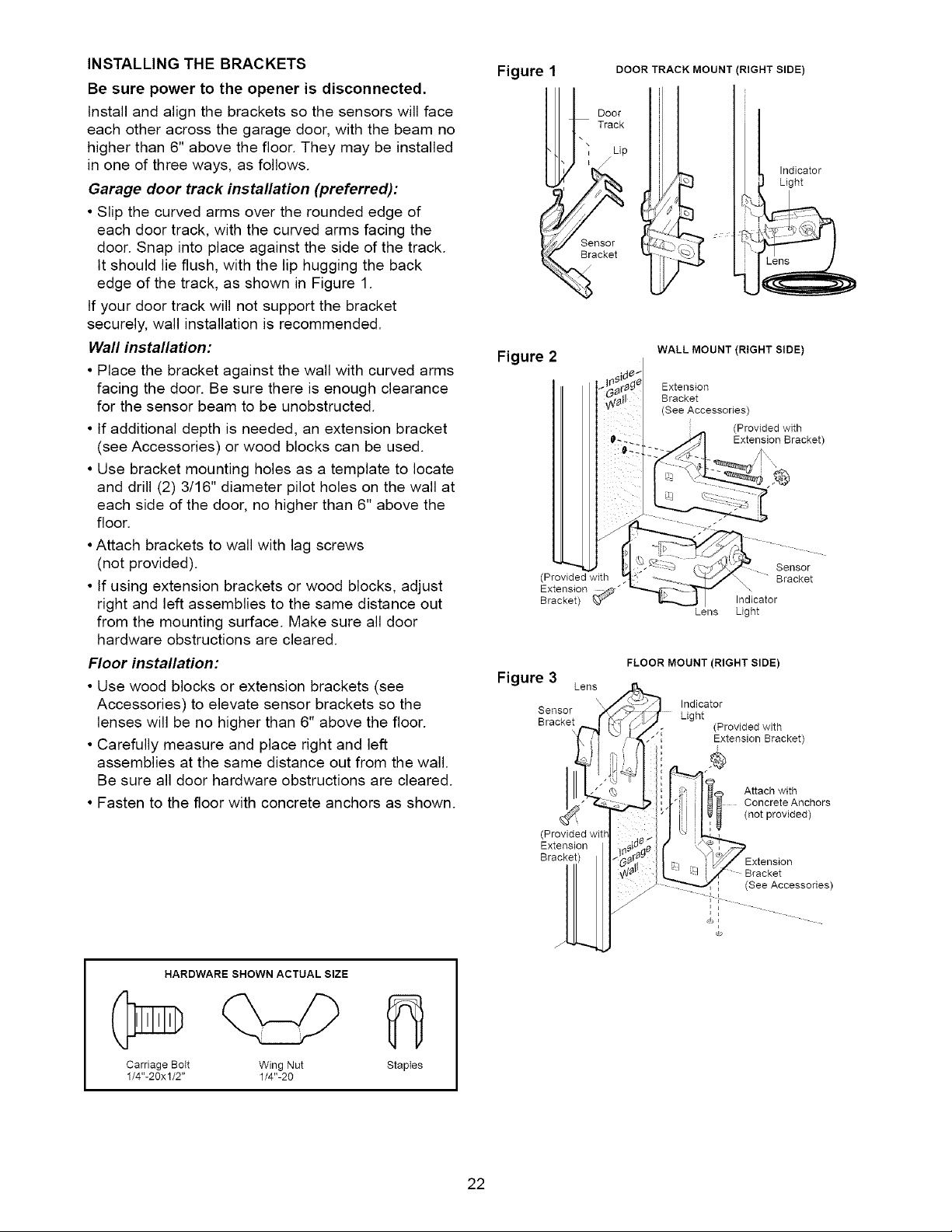
Garage door track installation (preferred):
• Slip the curved arms over the rounded edge of
each door track, with the curved arms facing the
door. Snap into place against the side of the track.
It should lie flush, with the lip hugging the back
edge of the track, as shown in Figure 1.
If your door track will not support the bracket
securely, wall installation is recommended.
Wall installation:
• Place the bracket against the wall with curved arms
facing the door. Be sure there is enough clearance
for the sensor beam to be unobstructed.
• If additional depth is needed, an extension bracket
(see Accessories) or wood blocks can be used.
• Use bracket mounting holes as a template to locate
and drill (2) 3/16" diameter pilot holes on the wall at
each side of the door, no higher than 6" above the
floor.
•Attach brackets to wall with lag screws
(not provided).
• If using extension brackets or wood blocks, adjust
right and left assemblies to the same distance out
from the mounting surface. Make sure all door
hardware obstructions are cleared.
Floor installation:
• Use wood blocks or extension brackets (see
Accessories) to elevate sensor brackets so the
lenses will be no higher than 6" above the floor.
• Carefully measure and place right and left
assemblies at the same distance out from the wall.
Be sure all door hardware obstructions are cleared.
• Fasten to the floor with concrete anchors as shown.
Figure 1
Figure 2
(Provided with
Extension
Bracket) _"
Figure 3
Sensor
Bracke_l
(Provided wit[
Extension
Bracket)
DOOR TRACK MOUNT (RIGHT SIDE)
Door
Track
\
Lip
Sensor
Bracket
WALL MOUNT (RIGHT SIDE)
Extension
Bracket
(See Accessories)
Lens Light
FLOOR MOUNT (RIGHT SIDE)
Lens
Indicator
Light
!l Attach with
i
Indicator
Light
(Provided with
Extension Bracket
Sensor
Bracket
\
Indicator
(Provided with
Extension Bracket)
Concrete Anchors
(not provided)
1 (See Accessories)
J
J
J
J
HARDWARE SHOWN ACTUAL SIZE
Carriage Bott Wing Nut
1/4"-20xl/2" 1/4"-20
Staptes
22
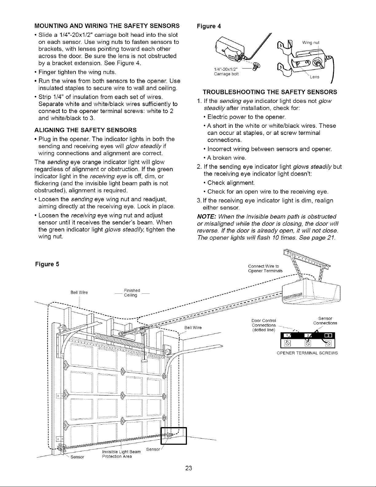
MOUNTING AND WIRING THE SAFETY SENSORS
• Slide a 1/4"-20xl/2" carriage bolt head into the slot
on each sensor. Use wing nuts to fasten sensors to
brackets, with lenses pointing toward each other
across the door. Be sure the lens is not obstructed
by a bracket extension. See Figure 4.
• Finger tighten the wing nuts.
• Run the wires from both sensors to the opener. Use
insulated staples to secure wire to wall and ceiling.
• Strip 1/4" of insulation from each set of wires.
Separate white and white/black wires sufficiently to
connect to the opener terminal screws: white to 2
and white/black to 3.
ALIGNING THE SAFETY SENSORS
• Plug in the opener. The indicator lights in both the
sending and receiving eyes will glow steadily if
wiring connections and alignment are correct.
The sending eye orange indicator light will glow
regardless of alignment or obstruction. If the green
indicator light in the receiving eye is off, dim, or
flickering (and the invisible light beam path is not
obstructed), alignment is required.
• Loosen the sending eye wing nut and readjust,
aiming directly at the receiving eye. Lock in place.
• Loosen the receiving eye wing nut and adjust
sensor until it receives the sender's beam. When
the green indicator light glows steadily, tighten the
wing nut.
Figure 4
Carriage bott
TROUBLESHOOTING THE SAFETY SENSORS
1. If the sending eye indicator light does not glow
steadily after installation, check for:
• Electric power to the opener.
•A short in the white or white/black wires. These
can occur at staples, or at screw terminal
connections.
• Incorrect wiring between sensors and opener.
•A broken wire.
2. If the sending eye indicator light glows steadily but
the receiving eye indicator light doesn't:
• Check alignment.
• Check for an open wire to the receiving eye.
3. If the receiving eye indicator light is dim, realign
either sensor.
NOTE: When the invisible beam path is obstructed
or misaligned while the door is closing, the door will
reverse. If the door is already open, it will not close.
The opener lights will flash 10 times. See page 21.
Figure 5
Bell Wire
Connect Wire to
Opener Terminals
Finished ..--''''''''"'''''"÷'"-'°
......... 1 Door Controt
BeII Wire
Connections
(dotted line) _
Sensor
Connections
OPENER TERMINAL SCREWS
\ Sensor
Invisible Light Beam
Protection Area
Sensor
23
 Loading...