

Page 1
Operator's ManuaM
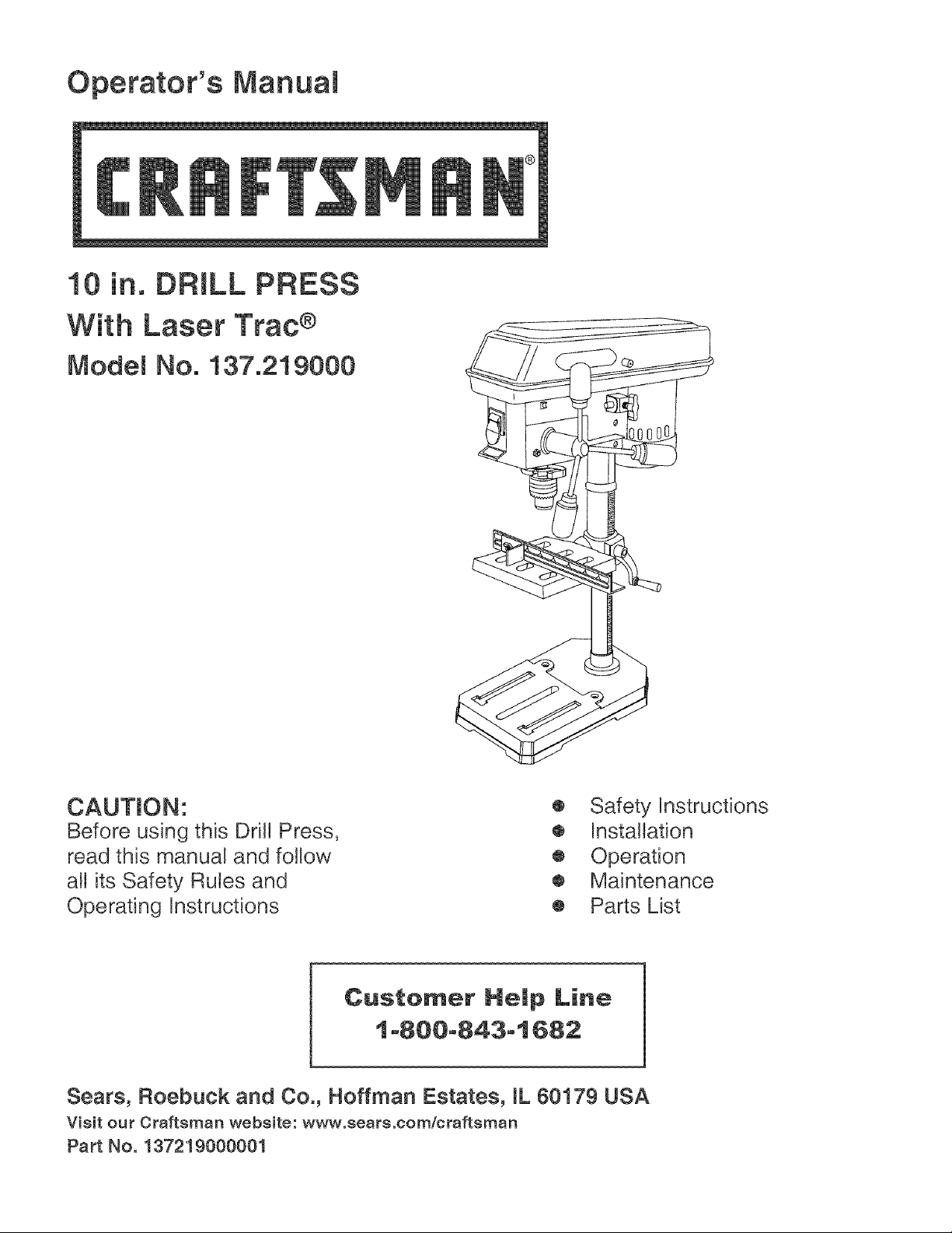
10 in. DRILL PRESS
With Laser Trac ®
Model No, 137,219000
.3
CAUTION:
Before using this DriJl Press,
read this manual and follow
all its Safety Rules and
Operating Instructions
o Safety Instructions
o Installation
® Operation
o Maintenance
• Parts List
Customer He_p Line
1-80@-843-1682
Sears, Roebuck and Co., Hoffman Estates, IL 60179 USA
Visit our Oraftsman website: www.sears.com/craftsman
Part No. 137219000001
Page 2

SECTmON PAGE
Warranty ........................................ 2
Product Specifications ....................... 2
Power Tool Safety ............................. 3
Drill Press Safety .................................. 4
Electrical Requirements and Safety ...... 5
Accessories and Attachments .............. 6
Tools Needed For Assembly ................ 6
Carton Contents .................................... 7
SECTmON PAGE
Know Your Drill Press ........................... 8
Glossary of Terms ............................. 9
Assembly and Adjustments ................. 10
Operation ........................................ 16
Maintenance ................................... 20
Troubleshooting Guide ........................ 21
Parts List ........................................... 22
ONE-YEAR FULL WARRANTY ON CRAFTSMAN TOOL
If this Craftsman too! fails due to a defect in material or workmanship within one year from the date of purchase,
CALL 1-800-4-MY-HOME ®TO ARRANGE FOR FREE REPAIR
If this too! is used for commercial or rental purposes, this warranty wil! apply for only ninety days from the date of
purchase. This warranty applies only while this tool is in the United States.
This warranty gives you specific bgal rights, and you may also have other rights, which vary, from state to state.
Sears, Roebuck & Co., Dept. 817 WA, Hoffman Estates, JL 60179
AWAn.I.G]
Some dust crested by power sanding, sawing, grinding, drilling and other construction activities contains
chemicals known to cause cancer, birth defects or other reproductive harm. Some examples of these
chemicals are:
Lead from lead-based paints
Crystalline silica from bricks, cement and other masonry products
Arsenic and chromium from chemically treated lumber
Your risk from these exposures varies, depending on how often you do this type of work. To reduce your
exposure to these chemicals, work in s well ventilated area and work with approved safety equipment such as
dust masks that are specially designed to filter out microscopic particles.
[AWAR"I"GI
To avoid electrical hazards, fire hazards or damage to the toot, use proper circuit protection.
This tool is wired st the factory for 110-120 Volt operation. It must be connected to s 110-120 Volt / 15 Ampere
time delay fuse or circuit breaker. To avoid shock or fire, replace power cord immediately if it is worn, cut or
damaged in any way.
Before using your tool, it is critics1 that you read and understand these safety rules. Failure to follow these
rules could result in serious injury to you or damage to the tool
Page 3
GENERAL SAFETY mNSTRUCTmONS
BEFORE USING THIS DRILL PRESS
Safety is a combination of common sense, stay alert
and knowing how to use your dril! press.
[AWARN NGI
14.REMOVE ADJUSTING KEYS AND WRENCHES.
Form habit of checking to see that keys and adjusting
wrenches are removed from the too! before turning it
ON.
15NEVER LEAVE A TOOL RUNNING UNATTEND.
TURN THE POWER "OFF". Don't leave the tool until
it comes to a complete stoG
To avoid mistakes that could cause serious injury,
do not plug the drill press in until you have read and
understood the following.
1. READ and become familiar with the entire instruction
manual. LEARN the tool's application, limitations and
possible hazards.
2. KEEP GUARDS tN PLACE and in working order.
3. DON'T USE tN DANGEROUS ENVIRONMENT.
Don't use power tools in damp and wet locations, or
expose them to rain. Keep work area well lighted.
4. DO NOT use power tools in the presence of
flammable liquids or gases.
5. KEEP WORK AREA CLEAN. Cluttered areas and
benches invited accidents.
6. KEEP CHILDREN AWAY. All visitors should be kept
safe distance from work area.
7. DON'T FORCE THE TOOL. It wi!l do the job better
and safer at the rate for which it was designed.
8. USE THE RIGHT TOOL. Do not force a tool or an
attachment to do a job for which it was not designed.
9. WEAR PROPER APPAREL. Do not wear loose
clothing, gloves, neckties, rings, bracelets, or other
jewelry which may get caught in moving parts.
Nonslip footwear is recommended. Wear protective
hair covering to contain long hair.
10.WEAR A FACE MASK OR DUST MASK. Sawing
operation produces dusL
11.DISCONNECT TOOLS before servicing; when
changing accessories such as blades, bits, cutters,
and the like.
12REDUCE THE RiSK OF UNINTENTIONAL
STARTING. Make sure the switch is in the off
position before plugging in.
1&USE RECOMMENDED ACCESSORIES. Consult
the owner's manual for recommend accessories. The
use of improper accessories may cause risk of injury
to persons.
16NEVER STAND ON THE TOOL. Serious injury
could occur if the tool is tipped or if the cutting tool is
unintentionally contacted.
17DON'T OVERREACH. Keep proper footing and
balance at al! times.
18.1VIAtNTAIN TOOLS WITH CARE. Keep tools sharp
and clean for best and safest performance. Follow
instructions for lubricating and changing accessories.
1&CHECK FOR DAMAGED PARTS. Before further
use of the tool, a guard or other part that is damaged
should be carefully checked to determine that it will
operate properly and perform its intended function
= check for alignment of moving parts, binding of
moving parts, breakage of parts, mounting, and any
other conditions that may affect its operation. A guard
or other part that is damaged should be properly
repaired or replaced.
2&MAKE WORKSHOP CHILD PROOF with pad!ocks,
master switches, or by removing starter key&
21 .DO NOT operate the tool if you are under the
influence of any drugs, alcoho! or medication that
could affect your ability to use the tool properly.
22.Dust generated from certain materiai can be
W_AR YOUR
2&ALWAYS WEAR EYE PROTECTION. Any drill
press can throw foreign objects into the eyes and
could cause permanent eye damage. ALWAYS
wear Safety Goggles (not glasses) that comply with
ANSi Safety standard Z87.1 Everyday eyeglasses
have only impact -resistance lenses. They ARE
NOT safety glasses. Safety Goggles are available at
Sears. NOTE: Glasses or goggles not in compliance
with ANSI Z87.1 could seriously hurt you when they
break.
hazardous to your health. Always
operate the drill press in a well-
ventilated area and provide for
proper dust removal. Use a dust
collection system whenever
possibb.
Page 4

[AWARNINGI
For your own safety, do not try to use your drill press or
plug it in until it is completely assembled and installed
according to the instructions, and until you have read
and understood this instruction manual:
1. YOUR DRILL PRESS MUST BE BOLTED securely
to a workbench. In addition, if there is any tendency
for your drill press to move during certain operations,
bolt the workbench yo the floor.
2. THiS DRILL PRESS is intended for use in dry
conditions, indoor use only.
14SECURE THE WORK. Use clamps or a vise to hold
the work when practical, it's safer than using your
hand and it frees both hands to operate tool
1&WHEN using a dril! press vise, always fasten to the
table.
16MAKE SURE all clamps and locks are firmly
tightened before drilling.
17SECURELY LOCK THE HEAD and table support to
the column, and the table to the table support before
operating the drill press.
3. WEAR EYE PROTECTION. USE A face or dust
mask along with safety goggles if drilling operation
is dusty. USE ear protectors, especially during
extended periods of operation.
4. DO NOT wear gloves, neckties, or loose clothing.
5. DO NOT try to dril! material too small to be securely
held.
6. ALWAYS keep hands out of the path of a drill bit.
Avoid awkward hand positions where a sudden slip
could cause your hand to move intothe dril! biL
7. DO NOT install or use any dril! bit that exceeds 175
mm (7 in.) in length or extends 150 mm (6 in.) below
the chuck jaws. They can suddenly bend outward or
break.
8. DO NOT USE wire wheels, router bits, shaper
cutters, circle (fly) cutters, or rotary planers on this
dril! press.
9. WHEN cutting a large piece of materia! ,make sure it
is fully supported at the table height.
10DO NOT perform any operation freehand. ALWAYS
hold the workpiece firmly against the table so it will
not rock or twisL Use clamps or a vise for unstable
workpieces.
11.MAKE SURE there are no nails or foreign objects in
the part of the workpiece to be drilled.
12.CLAMP THE WORKPIECE OR BRACE tT against
the left side of the column to prevent rotation. If it is
too short or the table is tilted, clamp itsolidly to the
table and use the fence provide&
13JF THE WORKPIECE overhangs the table such that
it will fall or tip if not held, clamp it to the table or
provide auxiliary support.
1&NEVER turn your dril! press on before clearing the
table of all objects (tools, scraps of wood, etc.)
19BEFORE STARTING the operation, jog the motor
switch to make sure the dril! bit does not wobble or
vibrate.
20lET THE SPINDLE REACH FULL SPEED before
starting to drill, if your drill press makes an unfamiliar
noise or if it vibrates excessively, stop immediately,
turn the drill press off and unplug. If do not restart the
unit until the problem is correcte&
21 DO NOT perform layout assembly or set up work on
the table while the drill press is in operation.
22.USE THE RECOMMENDED SPEED for any drill
press accessory and for different workpiece material.
READ THE INSTRUCTIONS that come with the
accessory.
23.WHEN DRiLLiNG large diameter holes, clamp the
workpiece firmly to the table. Otherwise, the bit may
grap and spin the workpiece at high speeds. DO
NOT USE fly cutters or multiple-part hole cutters, as
they can come apart or become unbalanced in use.
24MAKE SURE the spindle has come to a complete
stop before touching the workpiece.
2&TO AVOID INJURY from accidental starting, always
turn the switch "OFF" and unplug the dri!! press
before installing or removing any accessory or
attachment or making any adjustmenL
26KEEP GUARDS tN PLACE and in working order.
27.USE ONLY THE SELF-EJECTING TYPE CHUCK
KEY as provided with the dril! press.
Page 5
GROUNDINGINSTRUCTIONS
tNTHEEVENTOFA_,_ALFUNCTIONOR
BREAKDOWN,groundingprovidesapathofleast
resistanceforelectriccurrentandreducestheriskof
shock.Thistoolisequippedwithanelectriccordthat
hasanequipmentgroundingconductorandgrounding
plug.TheplugMUSTbepluggedintoamatching
receptaclethatisproperlyinstalledandgroundedin
accordancewithALLlocalcodesandordinances.
DONOTMODIFYTHEPLUGPROVIDED.Ifitwil!not
fitthereceptacle,havetheproperreceptacleinstalled
byaqualifiedelectrician.
IMPROPERCONNECTIONoftheequipmentgrounding
conductorcanresultinriskofelectricshock.The
conductorwiththegreeninsulation(withorwithout
yellowstripes)istheequipmentgroundingconductor.
Ifrepairorreplacementoftheelectriccordorplugis
necessary,DONOTconnecttheequipmentgrounding
conductortoa liveterminal.
CHECKwitha qualifiedelectricianorservicepersonnel
ifyoudonotcompletelyunderstandthegrounding
instructions,orifyouarenotsurethetoolisproperly
grounded.
USEONLY3-WIREEXTENSIONCORDSTHAT
HAVE3-PRONGGROUNDINGPLUGSAND3-POLE
RECEPTACLETHATACCEPTTHETOOL'SPLUG.
REPAIRORREPLACEDAMAGEDORWORNCORD
IMMEDIATELY.
3-Prong Ptug
ig Prong
Grounded
Grounding Lug
:ure This
is Connected to a
Known Ground
(When using 120 volts only)
Ampere Rating Total length of cord in feet
_lole than not mole than 25' 50' 100' 150'
0 6 18' 16' 16' 14'
10 18' 16' 14' 12'
16' 16' 14 ' 12'
Make sure your extension cord is in good condition.
When using an extension cord, be sure to use one
heavy enough to carry the current your product will
draw. An undersized cord wi!! cause a drop in line
voltage resulting in loss of power and overheating. The
table below shows the correct size to use according to
cord length and
nameplate ampere rating. If in doubt, use the next
heavier gauge. The smaller the gauge number, the
heavier the cord.
Be sure your extension cord is properly wired and
in good condition. Always replace a damaged extension
cord or have it repaired by a qualified person before
using it. Protect your extension cords from sharp
objects, excessive heat and damp or wet areas.
Use a separate electrical circuit for your tools. This
circuit must not be less than #12 wire and should
be protected with a 15 Amp time lag fuse. Before
connecting the motor to the power line, make sure the
switch is in the OFF position and the electric current is
rated the same as the current stamped on the motor
nameplate. Running at a lower voltage wil! damage the
motor.
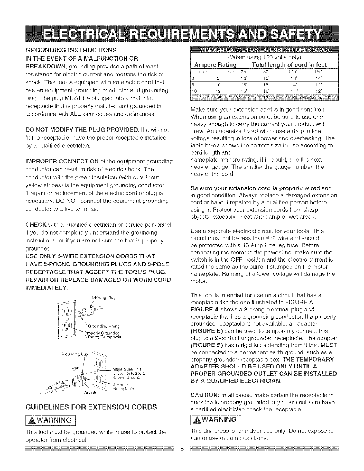
This tool is intended for use on a circuit that has a
receptacle like the one illustrated in FIGURE A.
FIGURE A shows a 3-prong electrical plug and
receptacle that has a grounding conductor, if a properly
grounded receptacle is not available, an adapter
(FIGURE B} can be used to temporarily connect this
plug to a 2-contact ungrounded receptacle. The adapter
(FIGURE B) has a rigid lug extending from it that MUST
be connected to a permanent earth ground, such as a
properly grounded receptacle box. THE TEMPORARY
ADAPTER SHOULD BE USED ONLY UNTIL A
PROPER GROUNDED OUTLET CAN BE INSTALLED
BY A QUALIFIED ELECTRICIAN.
Adapter
GUmDEUNES FOR EXTENSmON CORDS
[AWAR" "GI
This too! must be grounded while in use to protect the
operator from electrical.
CAUTION: In all cases, make certain the receptacle in
question is properly grounded. Ifyou are not sure have
a certified electrician check the receptacle.
IAWARNRNGI
This drill press is for indoor use only. Do not expose to
rain or use in damp locations.
Page 6
RECOMMENDED ACCESSORmES
UNPACKING AND CHECKING CONTENTS
[AWARN NGI
Use only accessories recommend for this drill press.
Follow instructions that accompany accessories. Use of
improper accessories may cause hazards.
Visit your Sears Hardware Department or see the Sears
Power and hand Tool Catalog for the follow accessories:
Drill bits
Hold-Down Clamps
Drill press Vises
[ WARN NGJ
Use only acessories designed for this drift press to
avoid injury from thrown broken parts or workpieces.
Sears may recommend other accessories not listed in
this manual See your neraest Sears store or Power and
Hand Tool Catalog for other accessorie&
Do not use any accessory unless you have completely
read the instruction or operator's manual for that
accessory.
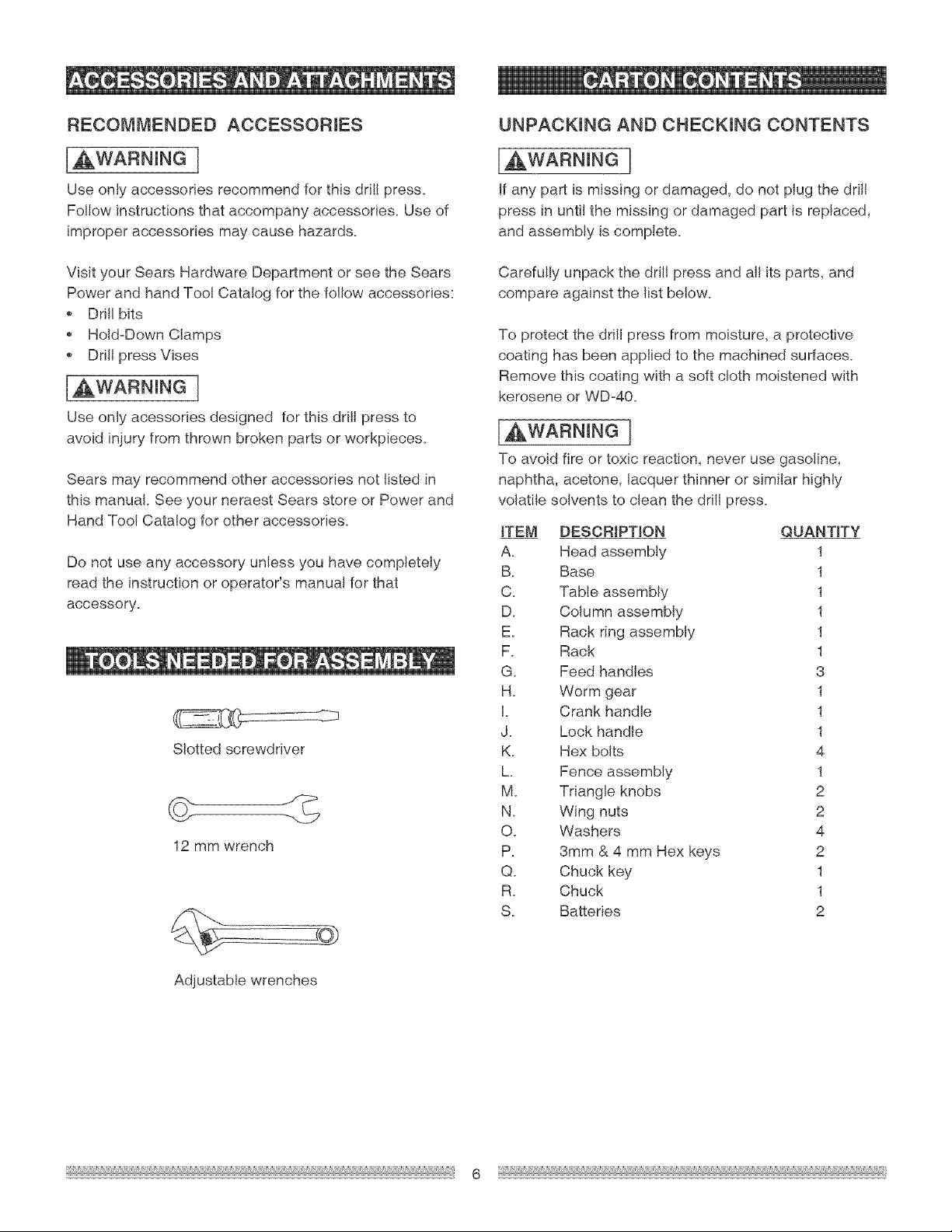
Slotted screwdriver
12 mm wrench
[AWARNmNG ]
If any part is missing or damaged, do not plug the drill
press in until the missing or damaged part is replaced,
and assembly is complete.
Carefully unpack the drift press and al! its parts, and
compare against the list below.
To protect the drill press from moisture, a protective
coating has been applied to the machined surfaces.
Remove this coating with a soft cloth moistened with
kerosene or WDo40.
[, ,WARNING J
To avoid fire or toxic reaction, never use gasoline,
naphtha, acetone, lacquer thinner or similar highly
volatile solvents to clean the dril! press.
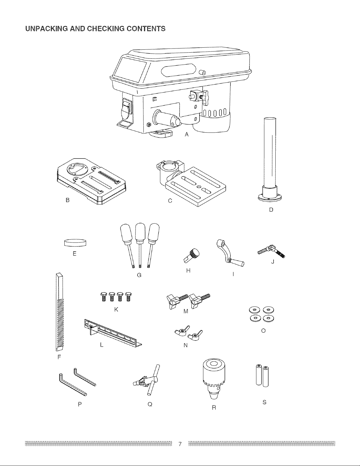
ITEM DESCRIPTION QUANTITY
A. Head assembly 1
B. Base 1
C. Table assembly 1
D. Column assembly 1
E. Rack ring assembly 1
F. Rack 1
G. Feed handles 3
H. Worm gear 1
L Crank handle 1
J. Lock handle 1
K. Hex bolts 4
h Fence assembly 1
M. Triangle knobs 2
N. Wing nuts 2
O. Washers 4
P. 3mm & 4 mm Hex keys 2
Q. Chuck key 1
R. Chuck 1
S. Batteries 2
Adjustable wrenches
Page 7
UNPACKING AND CHECKING CONTENTS
D
E
H
I
WWWW
K
O
N
# DD
Q S
R
Page 8
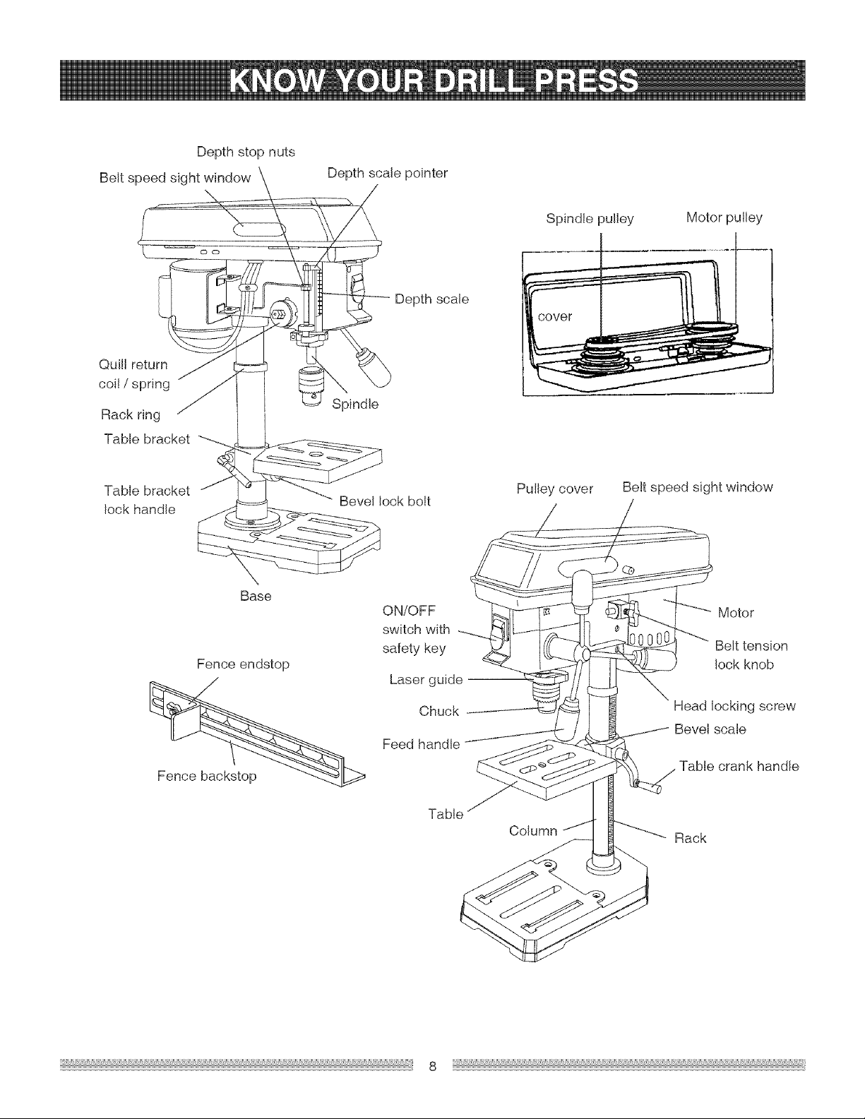
Beltspee_
Quill retu
coil / spring
Rack ring
Table bracket
Depth stop nuts
Oo
Depth scale pointer
- --C /
in
Depth scale
Spindle pulley
Motor pulley
Table bracket
lock handle
Base
Fence endstop
Bevel lock bolt
ON/OFF Motor
switch with
safety key Belt tension
Laser guide
Feed handle
Pulley cover
Belt speed sight window
lock knob
Chuck Head locking screw
Bevel scale
Table
Column
Rack
Page 9

BASE- Supports dril! press. For additional stability,
holes are provided in base to bolt drill press to
workbench.
HEAD LOCKING SCREWS - Locks the head to the
column. ALWAYS lock head in place while operating the
drill press.
BACKUP MATERIAL - A piece of scrap wood placed
between the workpiece and table. The backup board
prevents wood in the workpiece from splintering when
the drill passes through the backside of the workpiece. It
also prevents drilling into the table top.
BELT TENSION - Appropriate belt tenson is achived
with approximately 1/2 in. deflection.
BELT TENSION LOCK KNOB - Locks the motor
bracket support maintaining correct belt distance and
tension.
BEVEL SCALE - Shows degree of table angle for bevel
operations.
CHUCK - Holds a drill bit or other recommended
accessory to perform desired operations.
CHUCK KEY - A self-ejecting chuck key is provided
and designed to pop out of the chuck when you let go of
iL This action is designed to help prevent throwing of the
chuck key from the chuck when the power is turned ON.
Do not use any other key as a substitute.
ON/OFF SWITCH - incorporates a safety switch
key which can be removed to prevent access from
unauthorized users. Insert the key into the switch to turn
the drill press on.
PULLEY COVER ASSEMBLY - Covers the pulleys and
belt during operation of the drill press.
RACK - Combines with gear mechanism to provide
easy elevation of the table by the table crank handle.
RACK RiNG - Holds the rack to the column. Rack
remains movable in the collar to permit table support
movements.
REVOLUTIONS PER MINUTE (R.P.M) - The number
of turns completed by a spinning object in one minute.
SPINDLE SPEED - The R.PM. of the spindle.
SPRING CAP - Adjusts the quill return spring tension.
TABLE - Provides a working surface to support the
workpiece.
COLUMN - Connects the head, table, and base on a
one piece tube for easy alignment and movemenL
DEPTH SCALE - Indicates depth of hole being drilled.
DEPTH SCALE STOP NUTS - Can be adjusted to stop
the qui!! for certain depth drilling operations.
DRILL B_T - The cutting too! used in the drill press to
make holes in a workpiece.
DRiLLiNG SPEED - Changed by placing the belt in any
of the steps (grooves) in the pulleys. See the Spindle
Speed Chart inside belt guard.
FEED HANDLE - Moves the chuck up or down. One
or two of the handles may be removed if necessary
whenever the workpiece is of such unusual shape that it
interferes with the handle&
FENCE - Attaches to the table to align the workpiece
or for fast repetitive drilling. Remove fence when it
interferes with other drili press accessories.
TABLE BEVEL LOCK BOLT - Locks the table in any
position from 0° - 45°.
TABLE CRANK HANDLE - Elevates and lowers table.
Support lock handle must be released before operating
crank.
TABLE SUPPORT LOCK HANDLE - Tightening locks
the table support to the column. Always have it locked in
place while operating the dril! press.
TABLE BRACKET- Rides on the column to support
the table.
WORKPIECE - Material being drilled.
Page 10

ASSEMBLY JNSTRUCTmONS
[AWARNmNG1
For your own safety, never connect plug to power
source outlet until all assembly steps are complete and
you have read and understood the safety and operating
instructions.
NOTE: Table removed from bracket in illustration for
clarity.
Fig. B
[AWARN NGI
The drill press is a heavy power too! and should be
lifted with the help of two PEOPLE OR MORE to safely
assemble it.
ASSEMBUNG COLUMN TO BASE (FIG. A)
1. Position the base (2) on a flat worksurface.
2. Place the column (1) on the base, aligning the
mounting holes to the base.
3. Locate the three hex bolts (3) from the loose parts
bag.
4. Place a bolt in each hole through the column support
and thread into the base. Tighten with a 12ram
wrench.
Fig. A
1
3. Place the rack (5) inside the table bracket (3), making
sure the worm gear (1) on the inside of the table
bracket is engaged with the teeth of the rack and the
arrow stamped on the rack is pointing up.
Fig. C
INSTALLING TABLE TO COLUMN ASSEI_IBLY
(FIG. B THROUGH F)
1. Insert the worm gear (1) into the table crank handle
hole (2) from inside the table support (3). Make sure
the worm gear (1) meshes with the inside raising/
lowing gear_
2. Instal! the table bracket lock handle (4) into the hole
at the rear of the table bracket assembly. NOTE:
Instal! the handle from left to right, so it enters the
non-threaded side of the table bracket first as shown
in Fig. C.
10
Page 11

4_Slidethetableassemblywiththerackontothe
column.
5_Engagethebottomoftherack(5)withthelipofthe
columnsupport(6)_Tightenthetablebracketlock
handle(4)tolockthetableassemblytothecolumn.
7_Instal!thetablecrankhandle(9)ontothewormgear
shaft(11)onthesideofthetablesupport(12)_
8_Lineuptheflatsideoftheshaftwiththesetscrew(10)
inthecrankhandleandtightenthescrewwiththe
3mmhexwrenchprovided.
Fig.D
5
j6
J
6_ install the rack ring (7) on the column so the top lip of
the rack sits into the rack ring.
IMPORTANT: The bottom of the collar MUST NOT be
pushed all the way down onto the top of the rack. MAKE
SURE the top of the rack is under the bottom of the
collar and that there is enough clearance to al!ow the
rack to freely rotate around the column. Tighten the set
screw (8).
NOTE: To avoid column or collar damage, DO NOT
OVERTIGHTEN the set screw.
Fig.F
10
9
®
©
11
12
INSTALLING THE HEAD (FIG. G}
IAWARNINGI
The Drill Press head is heavy and should be lifted with
the help of two PEOPLE OR MORE to safely assemble
the drill press head on the column.
1. Carefully lift the head (1) and slide it into the
column (2). Make sure the head slides down over the
column as far as possible. Align the head with the
base.
2. Using the 4ram hex wrench provided, tighten the two
head locking setscrews (3) on the right side of the
head.
Fig. E
Fig. G
8
7
5
11
Page 12

tNSTALUNGFEEDHANDLES(FIG.H)
1_Threadeachfeedhandle(1)intothethreaded
holes(2)onthehubassembly(3)andTighten_
Fig.H
tNSTALUNGTHECHUCK(FIG.J,JANDK)
1. Cleanoutthetaperedholeinthechuck(1)witha
cleanclothanda non-alcoholbasedcleaner.Wipe
cleanalloilresideandanydirtorgrimethoroughly.
2. Cleantaperedsurfacesonthespindle(2)inthe
samemannerasabove.
NOTE:Makesuretherearenoforeignparticles
stickingtothesurfaces.Theslightestpieceofdirtor
oilresideonanyofthesesurfaceswillpreventthe
chuckfromseatingproperly.Thiswil!causethedrill
chuckandbittowobble.Iftaperedholeisextremely
dirty,useanon-alcohoJbasedcleaneronacleanrag
toclean.
4. Unlockthetablesupportlock(4-Fig.D)andswing
thetableawayfromthebottomofthechuck.
5. Usinga rubbermalletorahammerandablockof
wood,tapthechuckontothespindlefirmly(Fig.K).
Fig.K
MOUNTINGDRILLPRESSTOWORKSURFACE
(FIG.L}
1. If mountingthedrillpresstoaworkbench,asolid
woodbenchispreferredoveraplywoodboard,to
reducenoiseandvibration.
2. Holesshouldbepre-drilledthroughthesupporting
surface.
3. Thehardwareto mountthisdrillpressisNOT
suppliedwiththetoolThehardwareasshowninthe
illustrationshouldbeused:
@
Fig. t _l,ii,,_ Fig. L
1. Dril! press base
2. Bolt
3. Fiat washer
2
3. Open the jaws of the chuck (1) by rotating the chuck
sleeve clockwise. To prevent damage, make sure the
jaws are completely receded into the chuck, j 2
Fig. J
._:=__ 1 [I
2 _
4. Rubber washer
5. Worksurface
6. Flatwasher
7. Lockwasher
8. Hex nut
9. Jam nut
6 9
5 7 8
3
4
E_
I I
i i
12
Page 13

FENCE ASSEMBLY (FIG. M)
1_ Align the mounting holes of the fence over the table
slots.
2. Place a washer (2) on the threaded end of the knob
(3). Insert the knob through the mounting hole of the
fence and the table slot.
3. Place a washer and wing nut (4) on the knob from
under the table.
4. Repeat for the other knob and tighten.
Fig. M
ADJUSTMENTS mNSTRUCTmONS
NOTE: All the adjustments for the operation of the
drill press have been completed at the factory. Due to
normal wear and use, some occasional readjustments
may be necessary.
[a,WARNmNG]
To avoid injury from an accidenta! start, ALWAYS make
sure the switch is in the "OFF" position, the switch key
is removed, and the plug is not connected to the power
source outlet before making belt adjustments.
BEVEL DRILLING (FIG. N)
NOTE: A bevel scale has been included to measure
approximate bevel angle& If precision is necessary,
a square or other measuring tool should be used to
position the table. To use the bevel scale (6):
1. TIGHTEN the nut (4) on the locking pin using a
10mm or adjustable wrench clockwise to RELEASE
it from the table support.
2. Loosen the large hex head table bevel locking bolt (5)
using a 17ram or adjustable wrench.
3. Tilt the table, aligning the desired angle measurement
to the zero line opposite the scale (6).
4. Tighten the table bevel locking bolt (5).
5. To return the table to its original position, loosen the
table bevel locking bolt (5). Return the table (6) to the
0° position.
6. Return nut (4) on locking pin to the OUTSIDE END
OF THREADS. Gently tap locking pin until it is seated
in the mating hole of the table brackeL Hand tighten
nut (4).
NOTE: The table has been removed form the
illustration for clarity_
13
Fig. N
6
J
Page 14

[AWARNINGI
To prevent persona! injury, always disconnect the plug
from the power source when making any adjustments.
SPINDLE / QUILL (FIG. O)
Rotate the feed handles counterclockwise to lower
spindle to its lowest position. Hold the chuck and move
itfront to back. If there is excessive play, proceed with
the following adjustments:
1. Loosen the lock nut (1) located on the right side of
the drill press.
2. Turn the screw (2) clockwise to eliminate the play,
but without obstructing the upward movement of the
spindle. (A little play in the spindle is normaL)
3. Tighten the lock nut (1).
Fig.0
QUILL RETURN SPRING (FIG. P)
The quill return spring may need adjustment if the quil!
return speed is too rapid or too slow.
1. Lower the table for additiona! clearance.
2. Place a screwdriver in the lower front notch (1) of the
spring cap (2). Hold it in place while loosening and
removing only the outer jam nut (3).
3. With the screwdriver still engaged in the notch,
loosen the inner nut (4) just until the notch (5)
disengages from the boss (6) on the drit! press head.
NOTE: DO NOT REMOVE THIS INNER NUT,
because the spring will forcibly unwind.
4. Carefully turn the spring cap (2) counterclockwise
with the screwdriver, engaging the next notch.
5. Lower the quil! to the lowest position by rotating the
feed handle in a counterclockwise direction while
holding the spring cap (2) in position.
6. If the quill moves up and down as you desire, tighten
the inner nut (4) sung against the spring cap and
secure the outer nut (3) against the inner nut with the
adjustable wrench.
NOTE: DO NOT OVERTIGNTEN and restrict quil!
movement.
5
Fig. P 6
1
2
IAWARNmNGI
To avoid injury from an accidenta! start, ALWAYS make
sure the switch is in the "OFF" position, the switch key
is removed, and the plug is not connected to the power
source outlet before making belt adjustments.
BELT TENS!ON (FIG. Q)
1. To unlock the belt tension, turn the belt tension lock
knob (1) on the right side of the drill press head
counterclockwise.
2. Pull the motor (2) toward the front of the drill press to
loosen the belt tension.
3. Position the belt on the correct pulley steps for the
desired speed.
4. Push the motor away from the dril! press head until
the belt is properly tensioned.
NOTE: Belt tension is correct if the belt deflects
approximately 1/2 inch when pressed at its center.
5. Tighten the belt tension lock knob (1) to secure the
motor in position.
Fig.Q
J 2
THE LASER TRAC®
Your tool is equipped with our latest innovation, the
Laser Trac®, a battery powered device using Class
II laser beams. The laser beams wil! enable you to
preview the drill bit path on the workpiece to be drilled
before you begin your operation.
14
Page 15

[AWARNING I
AVOID DIRECT EYE CONTACT
A Laser light is radiated when the laser guide is turned
on. Avoid direct eye contact. Always un=plug the
drill press from the power source before making any
adjustments.
A laser pointer is not a toy and should not come into
hands of children. Misuse of this appliance can lead
to irreparable eye injuries.
Any adjustment to increase the laser power is
forbidden.
When using the laser pointer, do not point the laser
beam towards people and/or reflecting surfaces.
Even a laser beam of lower intensity may cause eye
damage. Therefore, do not look directly into the laser
beam.
If the laser pointer is stored for more than three
months without use, please remove the batteries to
avoid damage from possibly leaking batteries.
The laser pointer includes no servicing components.
Never open the housing for repair or adjustments.
On units equipped with the laser attachment, repairs
shall only be carried out by the laser manufacturer or
an authorized agent.
Laser Warning label: Max output <1mW DIODE
LASER:630=670nm, Complies with 21CFR 1040.10
and 1040. 11.
4_ Once adjustments are completed, retighten the four
screws (4)_
Fig. R
4
3
ADJUSTING THE LASER LINES ( FIG. R)
A. How to check the Laser-beam Alignment?
1. Adjust the table height so it is 5 in. below the bottom
of the chuck.
2. Scribe a round circle (approx. 1/8 in.) on a piece of
scrap wood.
3. insert a drill bit approx 1/8 in. diameter into the chuck
and tighten.
4. Lower the quill and align the scribed circle with the
drill bit and fasten the wood to the table.
5. Turn on the laser and verify the laser lines (x) are
centered onto the scribed circle.
B. ALIGNING THE LASER-BEAM (FIG. R)
To adjust the laser lines:
1. Turn on the laser by pressing the rocker switch.
2. Lower the drill press quil! and loosen one turn each
the four screws (4).
3. To adjust the laser beam left/right, turn the
adjustment screw (1) no more than 1/8 turn in either
direction. To adjust the laser beam front to back,
turn the adjusting screw (2) no more than 1/8 turn in
either direction.
15
Page 16

BASmC DRILL PRESS OPERATmONS
NOTE: This machine incorporates view windows on the
pulley cover used to observe the location of the belL
[AWARN NG!
To avoid possible injury, keep guard closed and in place
while tool is in operation.
J,AWARNINGj
ALWAYS lock the switch "OFF" when the drill press is
not in use by removing the safety switch key keep it in a
safe place. In the event of a power failure, blown fuse,
or tripped circuit breaker, turn the switch "OFF" and
remove the key, preventing an accidental startup when
power comes on.
SPEEDS AND BELT PLACEMENT (FIG. S)
This drill press has 5 speeds, as listed below:
620 RPM 1100 RPM 1720RPM
2340 RPM 3100 RPM
See inside of the pulley guard for specific placement of
the belts on the pulleys to change speeds.
Fig. S
620RPM 1100RPM 1720RPM
3100RPM2340RPM
ON/OFF SWITCH (FIG. T)
The ON / OFF switch has a removable, safety switch
key. With the key removed from the switch, unauthorized
and hazardous use by children and others are minimized
as the switch can not be turned on without the key
1. To turn the drit! press "ON", insert key (2) into the slot
of the switch (1). Move the switch upward to the "ON"
position.
2. To turn the driJl press "OFF", move the switch
downward.
3. To lock the switch in the OFF position, grasp the
sides of the safety switch key, and pult it out.
4. With the switch key removed, the switch wi!! not turn
the power tool on.
5. If the switch key is removed while the drill press
is running, it can be turned "OFF" but cannot be
restarted without inserting the switch key.
Fig. T
INSTALLING DRILL BIT IN CHUCK (FIG. U)
1. With the switch "OFF" and the switch key removed,
open the chuck jaws (1) using the chuck key (2). Turn
the chuck key counterclockwise to open the chuck
jaws (1).
2. insert the drill bit (3) into the chuck far enough to
obtain maximum gripping by the jaws, but not far
enough to touch the spirat grooves (flutes) of the drilJ
bit when the jaws are tightened.
3. Make sure that the drii! is centered in the chuck.
4. Turn the chuck key clockwise to tighten the jaws.
[_WARNING ]
To avoid injury or accident by the chuck key ejecting
forcibly from the chuck when the power is turned "ON",
use only the self-ejecting chuck key supplied with this
drill press. ALWAYS recheck and remove the chuck key
before turning the power "ON".
16
Page 17

Fig.U
1
3 "
USING THE FENCE (FIG. V)
The fence provides a way of accurately and quickly
setting up the workpiece for precision or for repitive
drilling operations.
1. Using a centerpunch or sharp nail, make an
indentation in the workpiece where you want to dril!.
2. Align the laser lines (x) with the indentation on the
workpiece.
3. Loosen the knobs (1) and slide the fence back stop (2)
firmly against the long side of the workpiece. Tighten
the knobs when in position.
4. Loosen the wing nut (3) and slide the end stop (4)
along the fence until it is firmly against the left side of
the workpiece. Tighten the wing nut.
5. Check the accuracy by drilling into a scrap workpiece
first. Adjust if needed.
6. Hold with your hand or clamp the top surface of the
workpiece firmly to prevent it from lifting off the table
when the bit is raised.
Fig. V
3 4
Workpieee method (Fig. W and X}
1. Mark the depth (1) of the hole on the side of the
workpiece (Fig. W).
2. With the switch "OFF", bring the drill bit (2) down until
the tip is even with the mark (Fig. W)
3. Hold the feed handle at this position.
4. Spin the lower nut (3) down to contact the depth stop
lug (6) on the head (Fig. X).
5. Spin the upper nut (5) down and tighten against the
lower nut (3) (Fig. X).
6. The drill bit will now stop after traveling the distance
marked on the workpiece.
Fig. W
2
Depth seete method (Fig. X)
Note: With the chuck in the upper position, the tip of
the drill bit must be just slightly above the top of the
workpiece.
1. With the switch "OFF", turn the feed handle until the
pointer (7) points to the desired depth on the depth
scale (4) and hold the feed handle in that position.
2. Spin the lower nut (3) down to contact the depth stop
lug (6)_
3. Spin the upper nut (5) against against the lower stop
nut and tighten.
4. The drill bit will stop after traveling the distance
selected on the depth scale.
DRILLING TO A SPECtFJC DEPTH
Drilling a blind hole (not all the way through workpiece)
to a given depth can be done two ways:
Drill mhole
Using a center punch or a sharp na{I, make an
indentation in the workpiece where you want to drill.
Turn on the laser assembly and align the laser lines (x)
with the indentation. Turn the power switch on and pul!
down on the feed handles with only enough effort to
allow the dril! to cut.
FEEDING TOO RAPIDLY might cause the belt or drill
to slip, tear the workpiece loose, or break the drill bit.
When driI!{ng metal, it will be necessary to lubricate the
tip of the drill bit with metal drilling oil to prevent it from
overheating.
17
Page 18

Fig,×
3 5 7
f
[AWAR"I"Gi
To avoid injury from an accidental start, ALWAYS make
sure the power switch is in the "OFF" position, the
switch key is removed, and the plug is not connected to
the power source outlet before removing or installing the
chuck.
BAS!C OPERATING INSTRUCTIONS
To get the best results and minimize the likelihood of
personal injury, follow these instructions for operating
your drill press.
[AWARN NGI
For your own safety, always read the SAFETY
INSTRUCTIONS listed within this operator's manual.
FOR YOUR PROTECTION
[AWARN NGI
To avoid being pulled into the power tool, do not wear
loose clothing, gloves, neckties, or jewelry. Always tie
back long hair.
1. if any part of your drill press is missing,
malfunctioning, damaged or broken, stop operation
immediately until that part is properly repaired or
replaced.
2. Never place your fingers in a position where they
could contact the drill bit or other cutting too!. The
workpiece may unexpectedly shift, or your hand
could slip.
3. To prevent the workpiece from being torn from your
hands, thrown, spun by the tool, or shattered, always
properly support your workpiece as follows:
a. Always position BACKUP MATERIAL (used
beneath workpiece ) so that it contacts the left
side of the column, or use the fence provided and
a clamp to brace the workpieces.
b. Whenever possible, position the workpiece to
contact the left side of the column, if it is too short
or the table is tilted, use the fence provided or
clamp solidly to the table, using the table s!ots.
c. When using a dril! press vise, always fasten it to
the table.
d. Never do any work freehand (hand-holding the
workpiece rather than supporting it on the table),
except when polishing.
e. Securely lock the head and support to the column,
the table arm to the support, and the table to the
table arm, before operating the dril! press.
fi Never move the head or the table while the tool is
running.
g. Before starting an operation, jog the motor switch
to make sure the drill or other cutting too! does
not wobble or cause vibration.
h. If a workpiece overhangs the table so it wi!! fa!l or
tip if not held, clamp it to the table or provide
auxiliary support.
L Use fixtures for unusual operations to adequately
hold, guide, and position workpiece.
j. Use the SPINDLE SPEED recommended for the
specific operation and workpiece material Check
the panel on the inside pulley cover or the chart
below for drilling speed information. For
accessories, refer to the instructions provided with
each accessory.
4. Never climb on the drill press table, it could break or
pull the entire dril! press down on you.
5. Turn the power switch "OFF", and put away the
switch key when leaving the drill press.
6. To avoid injury from thrown work or too! contact, do
not perform layout, assembly, or setup work on the
table while the cutting tool is rotating.
DRILUNG SPEED TABLE (RPM)
DRILLBit Material
Diam.
(inches)
1/16
1/8
3/16
1/4
5/16
3/8
1/2
Wood Alum., Zinc., Brass
3100 3100
2340
1720
234O
1100
iron, Steel
3100
2340
1720
1100
620
Page 19

POSITIONINGTHETABLE AND WORKPtECE
(FIG. AA AND BB)
1. Lock the table (1) to the column (2) at a position so
the tip of the drill bit (3) is just above the top of the
workpiece (4).
2. ALWAYS place a BACK-UP MATERIAL (scrap wood)
on the table beneath the workpiece. This will prevent
splintering or heavy burring on the underside of
the workpiece. To keep the back-up material from
spinning, it MUST be positioned against the LEFT
side of the column.
3. For a small piece that cannot be clamped to the
table, use a drill press vise (optional accessory).
[ WARNING I
To prevent the workpiece or backup material from being
thrown while drilling, you MUST position the workpiece
against the LEFT side of the column. Ifthe workpiece
or the backup material is not long enough to reach
the column, clamp them to the table, or use the fence
provided with the drift press to brace the workpiece.
Failure to secure the workpiece could result in personal
injury.
Fig. AA 3 ---.._ , _ 2
2. Turn the laser "ON" and align the laser lines (x) with
the indentation before turning the drill ON.
TILTING THE TABLE (FIG. CO)
NOTE: The table arm and support (1) has a predrilled
hole with a locking pin inserted for locking the table into
a predrilled 0° bevel angle.
1. TIGHTEN the nut (2) on the locking pin using a
10mm or adjustable wrench clockwise to RELEASE
it from the table support.
2. Loosen the large hex head table bevel locking bolt (3)
using a 17ram or adjustable wrench.
IAWARNINGI
To preventinjury,be sureto holdthetable& tablearm
assembly,so itwillnotswivelor tilt.
Fig. CO
4
(
2
4
[_WARNING I
A dritl press vise MUST be clamped or bolted to the
table to avoid injury from a spinning workpiece, or
damaged vise or bit parts.
Remove the drill press fence when it interferes with
other dril! press accessories.
Fig. BB
HOLDING A DRILLING LOCATION
I. Usinga centerpunchorsharpnail,make an
indentationintheworkpieoewhere you willbe
drilling.
3. Tiltthe table, aligning the desired angle measurement
to the zero line opposite the scale (4).
4. Tighten the table bevel locking bolt (3).
5. To return the table to its origina! position, loosen the
table bevel locking bolt (3). Return the table (1) to the
0° position.
6. Return nut (2) on locking pin to the OUTSIDE END
OF THREADS. Gently tap locking pin until it is
seated in the mating hole of the table bracket. Hand
tighten nut (2).
IAWARN N¢I
To avoid injury from spinning work or tool breakage,
always clamp workpiece and backup material securely
to the table before operating the drilI press.
FEEDING
1. Pulldown the feed handles with only enough effort to
allow the drift bit to cut.
2. Feeding too slowly might cause the drill bit to burn.
Feeding too rapidly might cause the belt or drill to
slip, tear the workpiece loose or break the drill bit.
3. When drilling meta!, it is necessary to lubricate the
drill bit tip with oil to prevent burning of the workpiece
and bit.
19
Page 20

[AWARNING]
For your own safety, turn the switch OFF and remove
the plug from the power source outlet before maintaining
or lubricating your dril! press_
Frequently blow out, using an air compressor or dust
vacuum, any dust that accumulates inside the motor.
Wear protective safety goggles.
[AWARNRNGj
To avoid shock or fire hazard, Jfthe power cord is worn
or cut in any way, have it replaced immediately.
LUBRICATmON
All of the drill press bal! bearings are packed with grease
at the factory. They require no further lubrication.
Periodically lubrbate the gear and rack, table elevation
mechanism of the spindle the rack (teeth) of the quill
Fig. DD
1
CHANGING THE LASER BATTERIES (FIG. DD)
Unplug your drill press.
[,AWARN NGI
Failure to unplug your too! could result in accidental
starting causing possible serious personal injury.
1. Open the battery cover (1).
2. Remove and replace the two batteries.
3. Replace the battery cover.
NOTE: Replace the batteries with batteries that have
a rating of 1.5 volts (Number 4 series and AAA size
or equivalent). When replacing the batteries, the
battery guide should be thoroughly cleaned. Use a soft
paintbrush or similar device, to remove al! sawdust and
debris.
2O
Page 21

[,&WARNINGI
To avoid injury from accidental starting, always turn switch OFF and unplug the tool before moving, replacing the blade
or making adjustments.
, Consult your Sears Service Center if for any reason the motor will not run.
PROBLEM POSSIBLE CAUSES REMEDY
Noisy operation 1. incorrect belt tension. 1. Adjust tension. See section "ASSEMBLY-
2. Dry spindle.
3. Loose spindle pulley.
4. Loose motor pulley.
Drill bit burn.
Run out of drill bit point-
drilled hole not round.
Wood splinters on
underside.
hand.
Drill bit binds in workpiece.
Excessive drill bit runout 1.
or wobble. 2.
Quill returns too slow or 1. Coil spring has improper 1. Adjust spring tension. See Section "ASSEMBLY -
too fast.
Chuck will not stay 1. 1.
attached to spindle. It fails
off when trying to install.
The laser guide wil! not 1. 1.
turn on. 2. 2.
1. incorrect spee&
2. Chips not coming out of hole.
3. Dulldrillbit.
4. Feeding too slowly.
5. Not lubricated.
1. Hand grain in wood or
lengths of cutting flutes and/
or angles not equal.
2. Bent drill bit.
1. No backup material under
workpiece.
1. Not supported or clamped 1. Support workpiece or clamp it.See Section "BASICWorkpiece torn loose from
properly.
Workpiece pinching drill bit, 1.
or excessive feed presure.
improper belt tension. 2.
Bent drillbit. 1.
Worn bearings. 2.
3.
Dril! bit not properly insta!led 3.
in chuck.
4.
Chuck not properly installed. 4.
tension.
Dirt, grease, or oil on the
tapered inside surface of
chuck or on the spJndle's
tapered surface.
The batteries are dead.
The battery contacts need
adjustment.
TENSIONING BELT"
2. Lubricate spindle. See Section "LUBRICATION".
3. Check tightenness of retaining nut on pulley, and
tighten if necessary.
4. Tighten set screw in motor pulley.
1. Change speed. See Section" BASIC DRILL PRESS
OPERATION- SPINDLE SPEEDS"
2. Retract drill frequently to clear chips.
3. Resharpen drill bit.
4. Feed fast enough - allow drill to cut.
5. Lubricate drill. See Section "BASIC DRILL PRESS
OPERATIONoFEEDING"
1. Resharpen drili bit correctly.
2. Replace dril! bit.
1. Use backup material. See Section "BASIC DRILL
PRESS OPERATION".
DRILL PRESS OPERATION".
Support workpiece or clamp it. See Section "BASIC
DRILL PRESS OPERATION".
Adjust tension. See Section" ASSEMBLY -
TENSIONING BELT".
Use a straight drill bit.
Replace bearings.
Instal! drill properly. See Section "BASIC DRILL
PRESS OPERATION" and "ASSEMBLY".
Install chuck properly. See Section "ASSEMBLY -
INSTALLING THE CHUCK".
ADJUSTMENTS -QUILL RETURN SPRING".
Using a non-alcohol based cleaner, clean the
tapered surface of the chuck and spindle to remove
all dirt, grease and oil. See Section "ASSEMBLY -
INSTALLING THE CHUCK".
Replace with new AAA batteries.
Tap outside the bottom and side of the laser housing
lightly with the but end of a screwdriver.
21
Page 22

10 in. DRmLL PRESS MODEL NO. 137.219000
[AWARNINGI
When servicing use only CRAFTSMAN replacement parts. Use of any other parts many create a HAZARD or cause
product damage.
[,_WARNING I
Any attempt to repair or replace electriea! parts on this Drill Press may create a HAZARD unless repair is done by a
qualified service technician. Repair service is availabJe at your nearest Sears Service Center.
PARTS LiST FOR SCHEI'_IATtC
I.D_NO_ DESCRIPTION SIZE
047U SET BOLT M10_1,5
047X POINTER
048K MOTOR ROD
048P FEEDSHAFT
048Z HANDLE BAR ASS'Y
0499 SPRING CAP ASS'Y
049C QUILL SETSCREW M8'_1.25-14
049S SPINDLE PULLEY #06
049Z MOTOR PULLEYASS'Y
04A5 CLAMP-CORD
04AD SWITCH BOX
04BM SWITCH COVER
04Q4 STICKER
04VT WORM
04WG SPRING
04WN MOTOR BASE
04XV PULLEYSETNUT
05SZ CHUCK KEY HOLDER
05TW NUT
05VD TABLE LOCK HANDLE M10_1 _5-25
05X8 SHIFTER BOLT M8"1.25-20
06SV CLAMP-CORD
0g2J CHUCK & KEY
0J3M HEX, WRENCH 3 mm
0J3P HEX, WRENCH 4 mm
0J4F FLAT WASHER @8X16-2.5
0J72 FLAT WASHER 1/4'_5/8-1/16
0J8F FLAT WASHER 1/4'_3/4-3/16
0J7F FLAT WASHER 5/16'_7/8-5/64
0JAF EXTERNAL TOOTH LOCK WASHER @5
0JCB SPRING PiN
0JJZ V-BELT
0JP4 HEX, HD. BOLT M8_1.25-16
0JQ7 HEX_HD. BOLT M8'_1.25-25
0JTA HEX, HD. BOLT 1/2_'12UNC-7/8
0JXE HEX_SOC_ SETSCREW M8"1.25-8
0K51 CR. RE. COUNT HD. SCREW M4_0.7-8
0K7K CR. RE. ROUND WASHER HD. SCREW M6_1.0-12
0K9X DRIVE SCREW @2.3-5
0KC6 CR. RE.TRUSSHD_ TAPPING SCREW M4"16-12
0KDH CR. RE. PAN HD. SCREW M5_0.8-8
0KDJ CR. RE. PAN HD_ SCREW M5_0.8-12
I.D. NO, DESCRIPTION SIZE
QTY QTY
0KFF CR. RE. PAN HD. SCREW M5_0.8-8
0KMS HEX. NUT M6_1.0 T=5
0KMY HEX. NUT M8_1.25 T=&5
0KPC HEX. NUT 3/8_24UNF T=8
0KQY LOCK NUT M8 '_1.25 T=8
0KSQ STRAIN RELIEF
0KUX TERMINAL
0LBD POWER CABLE
0LSC ROCKER SWITCH
0LWC ROCKER SWITCH
0SYV LOCATION PIN ASSY
0UGH DRIVING SLEEVEASSY
0V86 WARNING LABEL
0VSA CHUCK KEY
0VND HEAD #AW
0VPE SPEEDDIAGRAM
0WPL SWITCH KEY
0XF3 CRANK HANDLE ASS'Y
25B0 WARNING LABEL
25KA LASER STICKER
266Z PLUNGER HOUSING ASS'Y
26AN LASERASSY
28N2 BATTERIES
290M CAUTION LABEL
29FK CLEAR PANEL
29KU PULLEYCOVER ASS'Y #06
29L4 RACK
29R0 RACK RING ASSAY
29R1 TABLE BRACKET ASSAY
2A2F FENCE HARDWARE BAG ASS'Y
2A7V QUILL ASS'Y
2ARX BASE #06
2AS1 TABLE #AW
2AUB SCALE
2BOY OPERATOR'S MANUAL
2B7K COLUNM ASS'Y
2BJ1 MOTOR ASS'Y
2C05 TRADE-MARK LABEL
2C06 LABEL
2C07 SCALE
2C08 SPEEDDIAGRAM
22
Page 23

10 in. DRILL PRESS
SCHEMATIC
2C08
0KDH 3
_0UGH
OVPE
MODEL NO. 137.219000
OJJZ
048Z
0KSQ 2
o_
2C08
0L6D
OJP44
0KDJ
0KQY2
06SV
048K
04WG
0K7K
OKFF2 OKUX
047X
047U
/-
048P
04AD
0KDJ2
04BM
0KC62
OLWC
Page 24

Your Home
For repair - in your home - of all major brand appliances,
lawn and garden equipment, or heating and cooling systems,
no matter who made it, no matter who sold it!
For the replacement parts, accessories and
Operator's Manuals that you need to do-itoyourself.
For Sears professional installation of home appliances
and items like garage door openers and water heaters.
1-800-4-MY-HOME ® (1-8ooo4eeo4ee3)
CaiI anytime, day or night (U.S.A. and Canada)
www.sears.com www.sears.ca
Our Home
For repair of carry-in items like vacuums, lawn equipment,
and ebctronics, call or go ondine for the location of your nearest
Sears Parts & Repair Center.
1-800-488-1222
CaiI anytime, day or night (U.S.A. only)
www.sears.com
To purchase a protection agreement on a product serviced by Sears:
1-800-827-6655 (U.S.A.) 1-800-361-6665 (Canada)
Para pedir servioio de reparaci6n
a domicilio, y para ordenar piezas:
1-888oSU-HOGAR 3M
(1-888-784-6427)
® Registered Trademark / TM Trademark / SM Service Mark of Sears, Roebuck and Co.
@ Marca Registrada / TM Marca de Fb.brica / SM Marca de Servicio de Sears, Roebuck and Co.
MC Marque de commerce / MD Marque d6pos6e de Sears, Roebuck and Co. @ Sears, Roebuck and Co.
Au Canada pour service en frangais:
loS00-LE-FOYER "°
(1-800-533-6937)
www.sears.oa
2005.10 REV 2
 Loading...