

Page 1
Owner's Manual
SCROLLING SABRE SAW
Model No. 135.17243 __
Caution:
Before using this product,
read this manual and follow
all its Safety Rules and
Operating Instructions.
Sears, Roebuck and Co., Hoffman Estates, IL 60179
Safety
Operation
Maintenance
Parts
EspaSol, R 18
Page 2

Page
Warranty ..................................................... 2
Power Tool Safety Rules ...................................... 3-5
Symbols ..................................................... 6
Functional Description and Specifications ........................... 7
Assembly .................................................... 8
Operating Instructions ........................................ 8-11
Tool Tips ................................................. 11-14
Maintenance ................................................. 15
Service Parts .............................................. 16-17
EspaSol .................................................. 18-32
FULL ONE YEAR WARRANTY ON CRAFTSMAN
SCROLLING SABRE SAW
If this CRAFTSMAN Scrolling Sabre Saw fails to give complete satisfaction
within one year from the date of purchase, RETURN IT TO THE
NEAREST SEARS STORE IN THE UNITED STATES, and Sears will
replace it,free of charge.
If this CRAFTSMAN Scrolling Sabre Saw is used for commercial or rental
purposes, this warranty applies for only 90 days from the date of purchase.
This warranty gives you specific legal rights, and you may also have other
rights which vary from slate to state.
Sears, Roebuck and Co., Dept. 817WA, Hoffman Estates, IL 60179
-2-
Page 3
Read and understand all instructions. Failure to follow all instructions
listed below, may result in electric shock, fire and/or serious personal injury.
SAVE THESE INSTRUCTIONS
Work Area
Keep your work area clean and well lit.
Cluttered benches and dark areas invite
accidents.
Do not operate power tools in explosive
atmospheres, such as in the presence of
flammable liquids, gases, or dust. Power
tools create sparks which may ignite the dust
orfumes.
Keep by-standers, children, and visitors
away while operating a power tool.
Distractions can cause you to lose control.
Electrical Safety
Double Insulated tools are equipped with a
polarized plug (one blade is wider than the
other.) This plug will fit in a polarized outlet
only one way. If the plug does not fit fully
in the outlet, reverse the plug. If it still does
not fit, contact a qualified electrician to
install a polarized outlet. Do not change
the plug in any way. Double Insulation []
eliminates the need for the three wire
grounded power cord and grounded power
supply system. Before plugging in the tool, be
certain the outlet voltage supplied is within the
voltage marked on the nameplate. Do not use
'_4C only" rated tools with a DC power supply,
Avoid body contact with grounded
surfaces such as pipes, radiators, ranges
and refrigerators. There is an increased risk
of electric shock if your body is grounded. If
operating the power too! in damp locations is
unavoidable, a Ground Fault Circuit Interrupter
must be used to supply the power to your tool.
Electrician's rubber gloves and footwear will
further enhance your personal safety.
Don't expose power tools to rain or wet
conditions. Water entering a power tool will
increase the risk of electric shock.
Do not abuse the cord. Never use the cord
tocarry the tools or pull the plug from an
outlet. Keep cord away from heat, oil, sharp
edges or moving parts. Replace damaged
cords immediately. Damaged cords increase
the risk of electric shock.
When operating a power tool outside, use
an outdoor extension cord marked "W-A"
or "W." These cords are rated for outdoor use
and reduce the risk of electric shock. Refer to
"Recommended sizes of Extension Cords" in
the Accessory section of this manual.
Personal Safety
Stay alert, watch what you are doing and
use common sense when operating a
power tool. Do not use tool while tired or
under the influence of drugs, alcohol, or
medication. A moment of inattention while
operating power tools may result in serious
personal injury.
Dress properly. Do not wear loose clothing
or jewelry. Contain long hair. Keep your
hair, clothing, and gloves away from
moving parts. Loose clothes, jewelry, or long
hair can be caught in moving parts. Keep
handles dry, clean and free from oil and
grease.
Avoid accidental starting. Be sure switch
is "OFF" before plugging in. Carrying tools
with your finger on the switch or plugging in
tools that have the switch "ON" invites
accidents.
Remove adjusting keys or wrenches before
turning the tool "ON". A wrench or a key
that is left attached to a rotating part of the tool
may result in personal injury,
Do not overreach. Keep proper footing and
balance at all times. Proper footing and
balance enables better control of the tool in
unexpected situations.
Use safety equipment, Always wear eye
protection. Dust mask, non-skid safety
shoes, hard hat, or hearing protection must be
used for appropriate conditions.
Tool Use and Care
Use clamps or other practical way to
secure and support the workpiece to a
stable platform. Holdingthe work by hand or
against your body is unstable and may lead to
loss of control.
-3-
Page 4
Do not force tool. Use the correct tool for
your application. The correct tool will do the
job better and safer at the rate for which it is
designed.
Do not use tool if switch does not turn it
"ON" or "OFF". Any tool that cannot be
controlled with the switch is dangerous and
must be repaired.
Disconnect the plug from the power
source before making any adjustments,
changing accessories, or storing the tool.
Such preventive safety measures reduce the
risk of starting the tool accidentally.
Store idle tools out of reach of children
and other untrained persons, Tools are
dangerous in the hands of untrained users.
Maintain tools with care. Keep cutting
tools sharp and clean. Properly maintained
tools, with sharp cutting edges are less likely
to bind and are easier to control. Any
alteration or modification is a misuse and
may result in a dangerous condition.
Check for misalignment or binding of
moving parts, breakage of parts, and any
other condition that may affect the tools
operation. If damaged, have the tool
serviced before using. Many accidents are
caused by poorly maintained tools. Develop
a periodic maintenance schedule for your
tool,
Use only accessories that are
recommended by the manufacturer for
your model. Accessories that may be
suitable for one tool, may become hazardous
when used on another tool.
Service
Tool service must be performed only by
qualified repair personnel. Service or
maintenance performed by unqualified
personnel could result in a risk of injury. For
example: internal wires may be misplaced or
pinched, safety guard return springs may be
improperly mounted.
When servicing a tool, use only identical
replacement parts, Follow instructions in
the Maintenance section of this manual.
Use of unauthorized parts or failure to follow
Maintenance Instructions may create a risk
of electric shock or injury. Certain cleaning
agents such as gasoline, carbon
tetrachloride, ammonia, etc. may damage
plastic parts.
Hold tool by insulated gripping surfaces
when performing an operation where the
cutting tool may contact hidden wiring or
its own cord. Contact with a "live" wire will
make exposed metal parts of the tool "live"
and shock the operator. Do not drill, fasten
or break into existing walls or other blind
areas where electrical wiring may exist. If
this situation is unavoidable, disconnect all
fuses or circuit breakers feeding this
worksite.
Never leave the trigger locked "ON".
Before plugging the tool in, check that the
trigger lock is "OFF". Accidental start-ups
could cause injury.
Be aware of the location and setting of
the switch "Lock-ON" button. If the switch
is locked "ON" during the use, be ready for
emergency situations to switch it "OFF", by
first pulling the trigger then immediately
releasing it without pressing the "Lock-ON"
button,
Keep hands away from cutting area. Do
not reach under the material being cut.
The proximity of the blade to your hand is
hidden from your sight.
Keep hands from between the gear
housing and saw blade holder, The
reciprocating blade holder can pinch your
fingers.
Do not use dull or damaged blades. Bent
blade can break easily or cause kickback.
Before starting to cut, turn tool "ON" and
allow the blade to come to full speed.
Tool can chatter or vibrate if blade speed is
too slow at beginning of cut and possibly
kickback.
-4-
Page 5

Always wear safety goggles or eye
protection when using this tool. Use a
dust mask or respirator for applications
which generate dust.
Secure material before cutting. Never
hold it in your hand or across legs. Small
or thin material may flex or vibrate with the
blade, causing loss of control.
Make certain all adjusting screws and the
blade holder are tight before making a
cut, Loose adjusting screws and holders
can cause the tool or blade to slip and lose of
control may result.
When removing the blade from the tool
avoid contact with skin and use proper
protective gloves when grasping the
blade or accessory. Accessories may be
hot after prolonged use.
Use only accessories that are sold by
Sears for your model. Accessories that may
be suitable for one tool may become
hazardous when used on another tool.
_Some dust created by
power sanding, sawing,
grinding, drilling, and other construction
activities contains chemicals known to
cause cancer, birth defects or other
reproductive harm. Some examples of
these chemicals are:
• Lead from lead-based paints,
• Crystalline silica from bricks and cement
and other masonry products, and
• Arsenic and chromium from chemically-
treated lumber.
Your risk from these exposures varies,
depending on how often you do this type of
work. To reduce your exposure to these
chemicals: work in a well ventilated area, and
work with approved safety equipment, such
as those dust masks that are specially
designed to filter out microscopic particles.
-5-
Page 6

Symbols
IMPORTANT: Some of the following symbols may be used on your tool. Please study them
and learn their meaning. Proper interpretation of these symbols will allow you to operate the
tool better and safer.
Symbol Name
V Volts
A Amperes
Hz Hertz
W Watt
kg Kilograms
rain Minutes
s Seconds
_l Diameter
% No load speed
.../min
0
1,2,3 ....
I, It, III,
-.€,
I
[]
@
&
Revolutions or reciprocation per minute
Off position
Selector settings
Infinitely variable selector with off
Arrow
Alternating current
Direct current
Alternating or direct current
Class II construction
Earthing terminal
Warning symbol
Ni-Cad RBRC seal
@
Designation/Explanation
Voltage (potential)
Current
Frequency (cycles per second)
Power
Weight
Time
Time
Size of drill bits, grinding wheels, etc.
Rotational speed, at no load
Revolutions, strokes, surface speed,
orbits etc. per minute
Zero speed, zero torque...
Speed, torque or position settings.
Higher number means greater speed
Speed is increasing from 0 setting
Action in the direction of arrow
Type or a characteristic of current
Type or a characteristic of current
Type or a characteristic of current
Designates Double Insulated
Construction tools.
Grounding terminal
Alerts user to warning messages
Designates Ni-Cad battery recycling
program
This symbol designates
lhat this tool is listed by
Underwriters Laboratories.
that this tool is listed by
!_ This symbol designates
the Canadian Standards
Association.
0®
-6-
This symbol designates
that this tool is listed to
Canadian Slandards by
Underwriters Laboratories.
This symbol designates that
this tool is listed by
Underwriters Laboratories,
and listed to Canadian
Standards by Underwriters
Laboratories.
This symbol
designates
that
this tool
complies
to NOM
Mexican
Standards.
Page 7
F_i_I Disconnect the plug from the power source before making any
assembly, adjustments or changing accessories. Such preventive safety
measures reduce the risk of starting the tool accidentally,
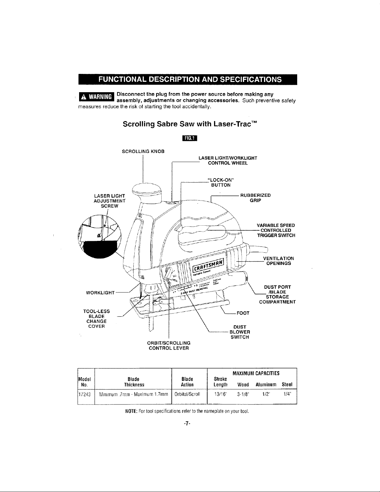
Scrolling Sabre Saw with Laser-Trac TM
SCROLLING KNOB
CONTROL WHEEL
LASER LIGHT
ADJUSTMENT
WORKLIGHT
TOOL-LESS
BLADE
CHANGE
COVER
/_f--_-. BUTTON
SCREW /
I LASER LIGHT/WORKLIGHT
ORBIT/SCROLLING
CONTROL LEVER
"LOCK-ON"
RUBBERIZED
FOOT
DUST
BLOWER
SWITCH
GRIP
VARIABLE SPEED
CONTROLLED
TRIGGER SWITCH
i VENTILATION
OPENINGS
DUST PORT
/BLADE
STORAGE
COMPARTMENT
Model Blade Blade Stroke
MAXIMUM CAPACITIES
No, Thickness Action Length Wood Aluminum Steel
17243 N1inmlum.7m111- Maximum 1.7ram Orbital/Scroll 13/16" 3-!/8" 1/2" 1/4"
NOTE:Fortool specifications refer to the nameplateon your tool.
-7=
Page 8
+a_ i6!9X0<427 9-G4 9/23/04 9 ;04 _i,__ P 8
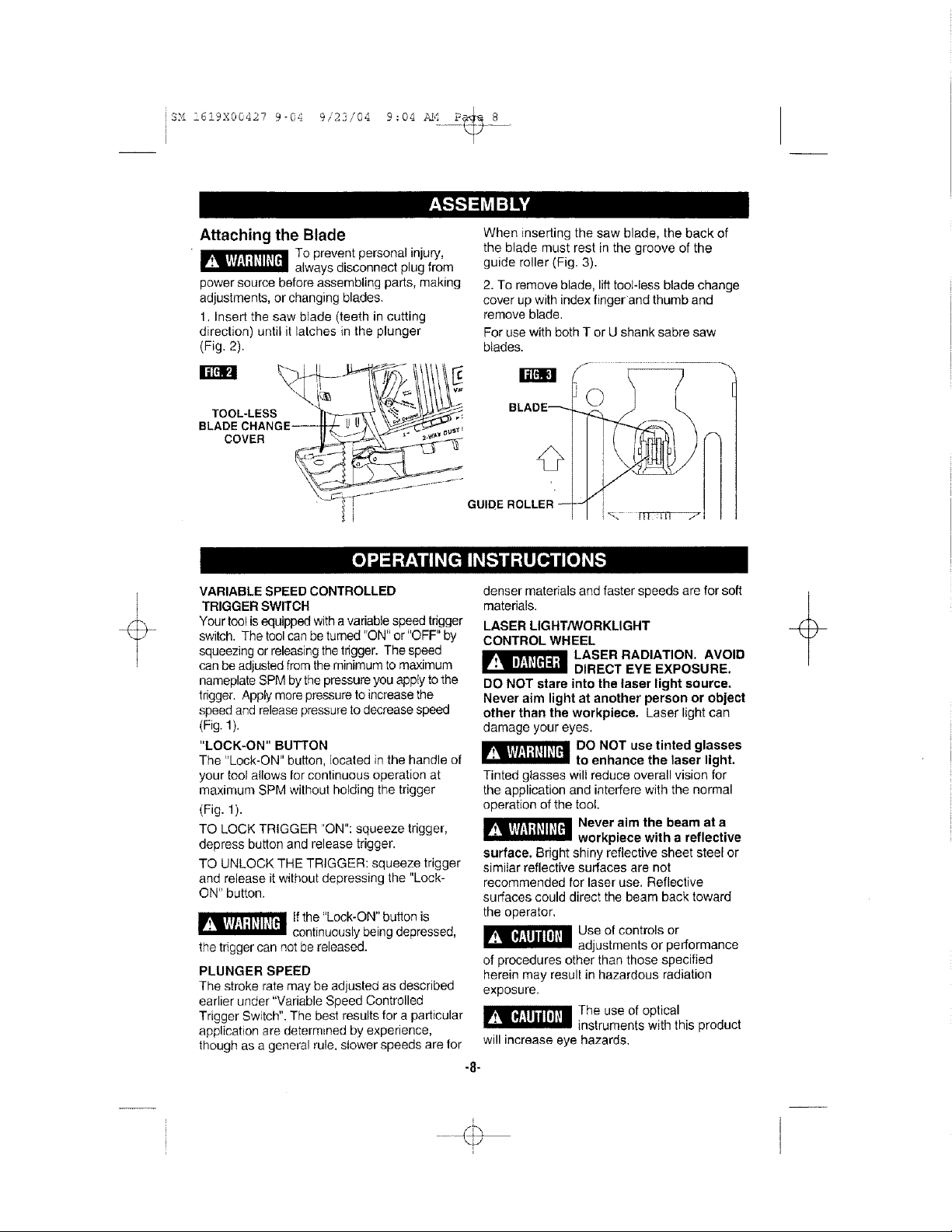
Attaching the Blade
To prevent personal injury,
always disconnect plug from
power source before assembling parts, making
adjustments, or changing blades.
1, Insert the saw blade (teeth in cutting
direction) until it latches in the plunger
(Fig. 2).
TOOL-LESS
COVER
VARIABLE SPEED CONTROLLED
TRIGGER SWITCH
Your tool is equipped with a variable speed trigger
switch, The tool can be turned 'rON" or "OFF" by
squeezing or releasing the trigger. The speed
can be adjusted from the minimum to maximum
nameplate SPM by the pressure you apply to the
trigger. Apply more pressure to increase the
speed and release pressure to decrease speed
(Fig. 1).
"LOCK-ON" BUTTON
The "Lock-ON" button, located in the handle of
your tool allows Ior continuous operation at
maximum SPM without holding the trigger
(Fig. 1).
TO LOCK TRIGGER "ON": squeeze trigger,
depress button and release trigger.
TO UNLOCK THE TRIGGER: squeeze trigger
and release it without depressing the "Lock-
ON" button.
lf the "Lock-ON" button is
continuously being depressed,
the trigger can not be released.
PLUNGER SPEED
The stroke rate may be adjusted as described
earlier under "Variable Speed Controlled
Trigger Switch". The best results for a particular
application are determined by experience,
though as a general rule, slower speeds are for
When inserting the saw blade, the back of
the blade must rest in the groove of the
guide roller (Fig, 3).
2. To remove blade, lift tool-less blade change
cover up with index finger and thumb and
remove blade.
For use with both T or U shank sabre saw
blades.
f ...........................
BLADE---+
GU DE ROLLER --
denser materials and faster speeds are for soft
materials.
LASER LIGHT/WORKLIGHT
CONTROL WHEEL
_ ASER RADIATION, AVOID
DO NOT stare into the laser light source.
Never aim light at another person or object
other than the workpiece. Laser light can
damage your eyes.
Tinted glasses will reduce overall vision for
the application and interfere with the normal
operation of the tool.
_ Never aim the beam at a
surface. Bright shiny reflective sheet steel or
similar reflective surfaces are not
recommended for laser use. Reflective
surfaces could direct the beam back toward
the operator,
of procedures other than those specified
herein may result in hazardous radiation
exposure.
will increase eye hazards.
DIRECT EYE EXPOSURE.
DO NOT use tinted glasses
to enhance the laser light,
workpiece with a reflective
Use of controls or
adjustments or performance
The use of optical
instruments with this product
-8-
÷
÷
Page 9
SM !6i9X00427 9-04 9/23/04 9:04 AM P_ 9
The 4 position control wheel allows you to
control the function of the lights. Below, lists
the function of each setting (Fig. 1).
Setting 1: Turns OFF all lights.
Setting 2: Turns ON only the laser light.
Setting 3: Turns ON both the laser light and
the worklight.
Setting 4: Turns ON only the worklight
The laser line guide is a class Ilia laser with a
maximum output power of 5.0m Watts and
conforms to 21 CFR 1040.10 and 1040.11.
LASER-TRAC TM LASER LINE GUIDE
The Laser-Trac line guide help you to follow
your cutting line with greater ease and
precision when making a cut.
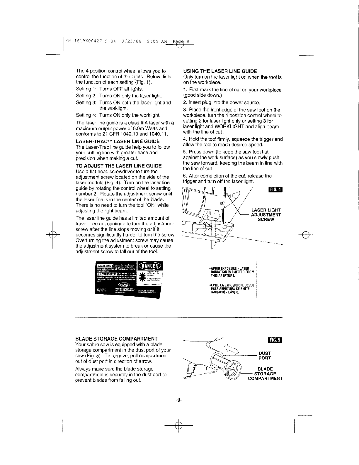
TO ADJUST THE LASER LINE GUIDE
Use a flat head screwdriver to turn the
adjustment screw located on the side of the
laser module (Fig. 4). Turn on the laser line
guide by rotating the control wheel to setting
number 2. Rotate the adjustment screw until
the laser line is in the center of the blade.
There is no need to turn the tool "ON" while
adjusting the light beam.
The laser line guide has a limited amount of
travel. Do not continue to turn the adjustment
screw after the line stops moving or if it
becomes significantly harder to turn the screw.
Overturning the adjustment screw may cause
the adjustment system to break or cause the
adjustment screw to fall out of the tool.
USING THE LASER LINE GUIDE
Onty turn on the laser light on when the tool is
on the workpiece.
1. First mark the line of cut on your workpiece
(good side down.)
2. Insert plug into the power source.
3. Place the front edge of the saw foot on the
workpiece, turn the 4 position control wheel to
setting 2 for laser light only or setting 3 for
laser light and WORKLIGHT and align beam
with the line of cut.
4. Hold the tool firmly, squeeze the trigger and
allow the tool to reach desired speed.
5. Press down (to keep the saw foot flat
against the work surface) as you slowly push
the saw forward, keeping the beam in line with
the line of cut.
6. After completion of the cut, release the
trigger and turn off the laser light.
I/
BLADE STORAGE COMPARTMENT
Your sabre saw is equipped with a blade
storage compartment in the dust port of your
saw (Fig. 5). To remove, pull compartment
out of dust port in direction of arrow,
Always make sure the bIade storage
compartment is securely in the dust port to
prevent blades from falling out.
-9-
•AVOID EXPOSURE- LASER
RADIATION IS EMITTEO FROM
THIS APERTURE. I
,,EVITELAEXPOSICII_N. DESDE I
ESTAABERTU.RASEEMITE
RADIACIOHLASER. I
COMPARTMENT
i"[i_1
DUST
PORT
BLADE
Page 10
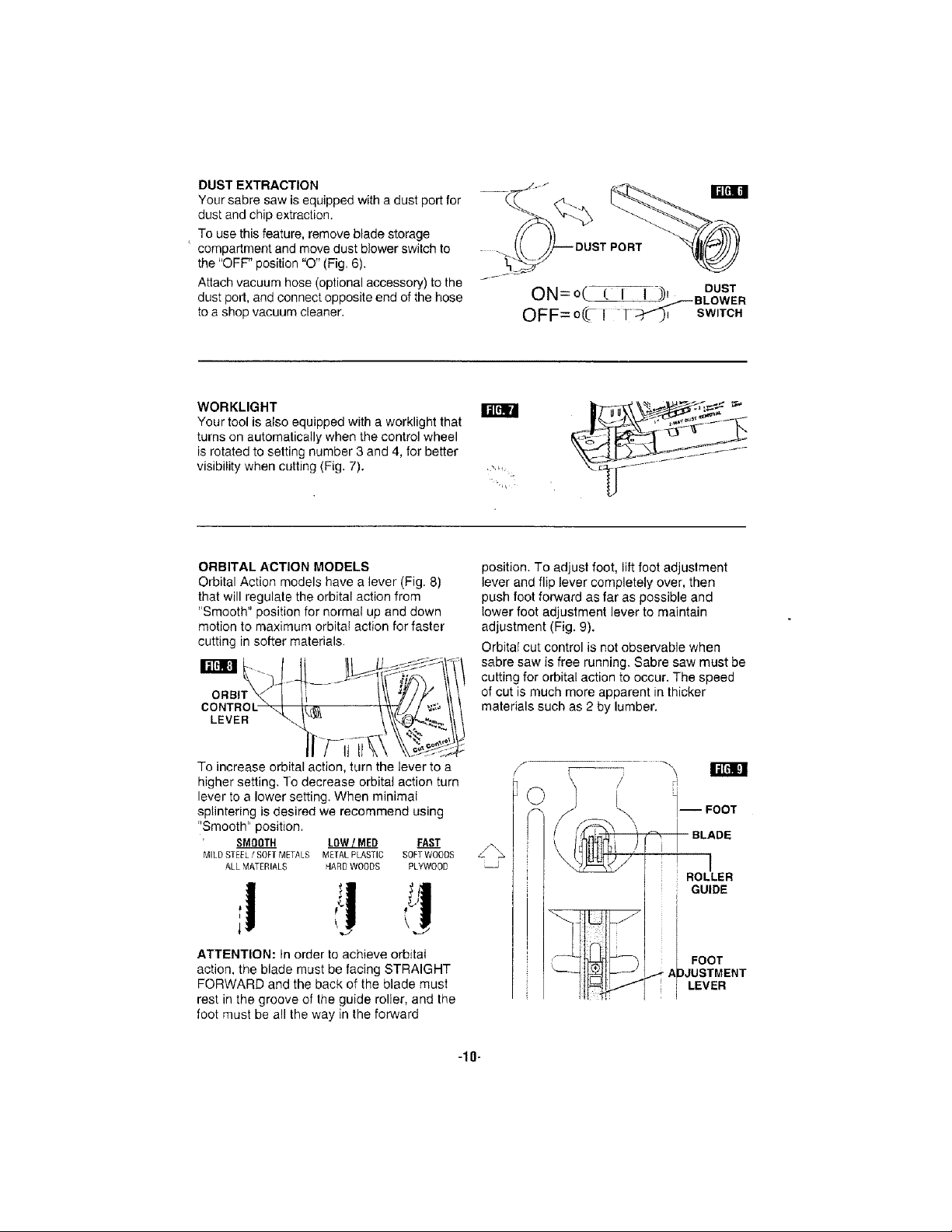
DUST EXTRACTION
Your sabre saw is equipped with a dust port for
dust and chip extraction,
To use this feature, remove blade storage
compartment and move dust blower switch to
the "OFF" position "O" (Fig, 6).
Attach vacuum hose (optional accessory) to the
dust port, and connect opposite end of the hose
to a shop vacuum cleaner.
ON=o( ( I 1 3)1 DUST
,-.--"-BLOWER
OFF=o(C ! 1:_" SWITCH
WORKLIGHT
Your tool is also equipped with a worklight that
turns on automatically when the control wheel
is rotated to setting number 3 and 4, for better
visibility when cutting (Fig. 7).
ORBITAL ACTION MODELS
Orbital Action models have a lever (Fig. 8)
that will regulate the orbital action from
"Smooth" position for normal up and down
motion to maximum orbital action for faster
cutting in softer materials.
To increase orbital action, turn the lever to a
higher setting. To decrease orbital action turn
lever to a lower setting. When minimal
splintering is desired we recommend using
"Smooth" position.
SMOOTH LOW!MED FAST
MILD STEEL/ SOFT METALS METAL PLASTIC SOFT WOODS
ALL MATERIALS "lARD WOODS PLYWOOD
I_[dlM
position. To adjust foot, lift foot adjustment
lever and flip lever completely over, then
push foot forward as far as possible and
lower foot adjustment lever to maintain
adjustment (Fig. 9).
OrbitaI cut control is not observable when
sabre saw is free running. Sabre saw must be
cutting for orbital action to occur. The speed
of cut is much more apparent in thicker
materials such as 2 by lumber.
I
ROLLER
GUIDE
ATTENTION: In order to achieve orbital
action, the blade must be facing STRAIGHT
FORWARD and the back of the blade must
rest in the groove of the guide roller, and the
foot must be all the way in the forward
FOOT
tpJUSTMENT
LEVER
-10-
Page 11

SCROLL MODELS
Scrolling saws permit 360 °rotation of the saw
blade without turning the saw, so intricate
designs may be cut with minimum effort. To
permit rotation of plunger turn lever, (Fig. 10)
to scrolling. The plunger of your scrolling saw
can also be locked in (4) positions, 90" apart.
ATTENTION: When scroll cutting the blade
must be moved away from the guide rollers
(aIways move foot completely back). To
adjust foot, lift foot adjustment lever and flip
lever completely over, then push foot
backwards as far as possible to engage
locking tab, then lower the foot adjustment
lever to maintain ac ustment (Fig. 11).
Note: It may be necessary to turn scrolling
knob slightly back and forth to be sure the
plunger is locked in the desired position.
J
SCROLLING
KNOB
When manually scroll cutting, operate saw by
holding the handle with one hand and rotating
the scrolling knob manually with your free
hand.
_ xcessive side pressure to
broken blades and/or damage to the material
being cut.
Note: When scroll cutting intricate designs,
we recort/mend using a scroll cutting blade.
However, a standard blade can be used.
Face the good side of the material down and
secure it in a bench vise or clamp it down.
Draw cutting lines or designs on the side of
the material facing up towards you. Then
place the front edge of the saw foot on the
work and line up the blade with the line to be
cut. Hold the sabre saw firmly, turn it on, and
press down (to keep the saw foot flat against
the work) as you slowly push the saw in the
direction of the cut.
Build up cutting rate gradually, cutting close to
the line (unless you want to leave stock for
finish sanding). As you cut you may have to
the blade could result in
\
I_[liH
©
I'JC
I
ROLLER
GUIDE
adjust or relocate the vise or clamps to keep
the work stable. Do not force the saw or the
blade teeth may rub and wear without cutting
and the blade may break. Let the saw do most
of the work. When following curves, cut slowly
so the blade can cut through cross grain. This
will give you an accurate cut and will prevent
the blade from wandering.
CUTTING WITH A STRAIGHTEDGE
Always use a rough cut blade when possible,
Clamp a straightedge on the work parallel to
the line of cut and flush with the side of the
saw foot, (Either first mark the line of cut and
-11-
Page 12

then position the straightedge parallel and at
the same distance as between the blade and
the side edge of the foot or first mark the side
edge of the foot and then clamp the
straightedge on the mark and parallel to the
cut line Fig. 12).
On models with the scroll feature, it is advised
to lock scroller knob.
As you cut, keep the saw foot edge flush
against the straightedge and fiat on the
workpiece (Fig. 12).
PLUNGE CUTTING
Plunge cutting is useful and time-saving in
making rough openings in softer materials. It
is not necessary to drill a hole for an inside or
pocket cut. Draw lines for the opening, hold
the saw firmly, tilt it forward so that the toe of
the saw foot rests on the work, but with the
blade well clear of the work. Start the motor,
and then very gradually lower the blade.
When it touches, continue pressing down on
the toe of the saw foot slowly pivoting the saw
like a hinge until the blade cuts through and
the foot rests flat on the work. Then saw
ahead on the line of cut line. We do not
recommend plunge cutting with a scroll blade
(Fig. 13).
To make sharp corners, cut up to the corner,
then back up slightly before rounding the
BEVEL OR ANGLE CUTTING
To prevent damage to the
tool when bevel or angle
cutting, the scroll mechanism must be locked
in place with the cutting edge of the blade
facing the front of the tool.
Disconnect the cord from the power source.
The foot can be adjusted to cut any angle
lrom 0 ° to 45," and is equipped with quick
reference detent stops at 0°, 15°, 30 °, and 45 °.
TO ADJUST: Lift foot adjustment lever in the
bottom of foot as shown, move foot slightly
backward to disengage the locking tab
(Fig. 14).
Position foot to desired angle, then push
forward to engage locking tab and lower
adjustment lever to maintain adjustment. After
adjusting foot make a sample cut to check the
angle (Fig. 14).
corner. After the opening is complete, go back
to each corner and cut it from the opposite
direction to square it off. Do not try to plunge
cut into hard materials such as steel.
J
Note: If the foot becomes loose you can use a
screwdriver to tighten screw located on the
foot adjustment lever, then re-adjust the loot
adjustment lever.
FOOT
ADJUSTMENT
SCREW-_ LEVER
TAB
-12-
Page 13

METAL CUTTING
When cutting metal clamp material down. Be
extra certain that you move the saw along
slowly. Use lower speeds. Do not twist, bend,
or force the blade. If the saw jumps or
bounces, use a blade with finer teeth, if the
blade seems clogged when cutting soft metal,
use a blade with coarser teeth.
For easier cutting, lubricate the blade with a
stick of cutting wax, if available, or cutting oil
when cutting steel. Thin metal should be
sandwiched between two pieces of wood or
tightly clamped on a single piece of wood
(wood on top of the metal). Draw the cut lines
or design on the top piece of wood.
When cutting aluminum extrusion or angle
iron, clamp the work in a bench vise and saw
close to the vise jaws.
When sawing tubing and the diameter is
larger than the blade is deep, cut through the
wail of the tubing and then insert the blade
into the cut rotating the tube as you saw.
RIP FENCE AND CIRCLE CUTTING GUIDE
This accessory is available at an extra cost. It
is used for fast and accurate straight and
circle cutting (Fig. 15).
CLAMp..--.---._
ATTACHING RIP FENCE
1. Insert bar of rip fence through the slots
provided in foot, from either side of loot with
the edge guide facing down (Fig. 15).
CLAMP _
SCREW
2. Thread the clamp screw from under the foot
through the threaded hole in the clamp on left
side of foot, and securely tighten clamp screw I
with a screwdriver, to clamp the rip fence bar
in place,
EDGE GUIDE DOWN
SLOT
I
I
STRAIGHT CUTTING CLAMP ,
Once the rip fence is attached, measure from , _
SCREW /
the edge of work to the line of cut, and set edge
guide of rip fence to the same distance and
then securely tighten clamp screw
(Fig. 16).
LINE OF CUT
-13-
DESIRED___
WIDTH
Page 14

CIRCLE CUTTING
1. Before attaching the rip fence, draw a circle
and drive a finishing nail in the center of circle.
2. Drill or plunge cut near the circles edge,
turn saw off and disconnect the plug from
power source (Fig. 17).
3. Attach rip fence to saw with the edge guide
facing UP.
4. Place the metal center point on the edge
guide into the hole in the center of the circle.
In order for the edge guide to cut a circle, the
metal center point MUST BE in alignment with
saw blade (see Fig. 18).
5. Measure the distance from the selected
hole to the bIade to be equal to the circle
radius.
6. Insert plug into power source, hold the saw
firmly, squeeze trigger and slowly push the
saw forward. To make a hole, cut from inside
the circle; To make wheels or discs, cut from
the outside.
Cutting Tip: Cut slowly so the blade will stay
straight in the cut. Place small wedges in the
cut as shown in Fig. 17, to keep the inner
circle from spreading when near the end of
the cut.
(
\ J
EDGE "WEDGE
GUIDE UP
BLADE MUST BE IN ALIGNMENT
WITH METAL CENTER POINT
-14-
Page 15

Service
_ reventive maintenance
orized personnel may result in misplacing
of internal wires and components which
could cause serious hazard. We
recommend that all tool service, including
service of laser, be performed by a Sears
Service Parts and Repair Center.
Tool Lubrication
Your tool has been properly lubricated and is
ready to use. It is recommended that tools
with gears be regreased with a special gear
lubricant at every brush change.
Carbon Brushes
The brushes and commutator in your toot have
been engineered for many hours of dependable
service. To maintain peak efficiency of the
motor, we recommend every two to six months
the brushes be examined. Only genuine Sears
replacement brushes specially designed for
your tool shouid be used.
Bearings
After about 300-400 hours of operation, or at
every second brush change, the bearings
performed by unauth-
should be replaced at an Authorized Service
Center. Bearings which become noisy (due to
heavy load or very abrasive material cutting)
should be replaced at once to avoid
overheating or motor failure.
Cleaning
I__1 To avoid accidents always
the power supply before cleaning or
performing any maintenance. The tool may
be cleaned most effectively with compressed
dry air. Always wear safety goggles when
cleaning tools with compressed air.
Ventilation openings and switch levers must
be kept clean and free of foreign matter. Do
not attempt to clean by inserting pointed
objects through openings.
_ ertain cleaning agents
plastic parts. Some of these are: gasoline,
carbon tetrachloride, chlorinated cleaning
solvents, ammonia and household
detergents that contain ammonia.
disconnect the tool from
and solvents damage
_lf an extension cord is necessary, a cord with adequate size conductors
that is capable of carrying the current necessary for your tool must be
used. This will prevent excessive voltage drop, loss of power or overheating. Grounded tools
must use 3-wire extension cords that have 3-prong plugs and receptacles.
RECOMMENDED SIZES OF EXTENSION CORDS
120 VOLT ALTERNATING CURRENT TOOLS
Tool's
Ampere
Rating
3-6
68
8-10
10-12
12-16
NOTE: The smaller the gauge number, the heavier the cord.
Cord Size in A.W.G.
Cord Length in Feel
25 50 100 150
18 16 16 14
18 16 14 12
18 16 14 12
16 16 14 !2
14 12
Wire Sizes in mm2
Cord Length in Meters
15 30 60 120
0.75 0,75 1.5 2.5
0.75 1,0 2.5 4.0
0.75 1.0 2.5 4.0
1.0 2.5 40 --
-15-
Page 16

CRAFTSMANSCROLLINGSABRESAWMODEL
NUMBER135.17243
2
13
.810
/
19
I
28
65"
832
34
t
,=
35
29
42
61
14
850
67
30
75
70
71
74
SIERRADEVAIVE:NPARAHACERCONTORNOSCRAFTSMAN
NUMERODEMODELO135.17243
Page 17

KEY PART
NO. NO.
1 2610916229
2 2610913978
3 2610913979
4 2610924106
5 2610916910
13 2610967219
14 2610917489
15 2610018632
16 2610320548
19 2914201705
21 2610329898
22 2610968496
23 2610329896
28 2610914014
29 2610913999
30 2610914016
34 2610914010
35 2610914007
42 2610914011
52 2610914015
54 2610916883
55 2610914018
56 2610914884
57 2610913996
58 2610914020
59 2610914019
60 2610914022
61 2610913993
62 2610913994
PART NAME
Housing
Field
Armature
Switch
Cord
Bushing
Ball Bearing
Retaining Ring
Brush Holder
Screw
Spring
Cable
Terminal Clip
Pusher
Counterweight
Shaft
Bushing
Bushing
Spring Clip
Arm
Foot
Bracket
Roller
Pin
Spring Clip
Holder
Pin
Yoke
Bolt
KEY
NO.
1
63
1
64
I
65
1
66
1
67
1
68
1
69
1
70
2
71
12
73
2
74
2
75
2
76
1
78
t
79
t
8O
1
81
1
84
1
85
1
86
1
87
1
88
1
810
1
826
2
832
1
836
1
844
1
85O
1
PART
NO.
2610913995
2610913992
2610917358
2610924134
2610916536
2610390329
2610912487
2610916094
2914201672
261O922316
2610924140
2914201664
261O916537
2610018199
2918150120
2610916541
2610917102
2610922519
2610922520
2610923594
2610924145
2610924146
2610917266
2610917218
261O917219
2610917220
2610917221
2610917222
261O924135
PART NAME
Nut
Lever
Locking Tang
Board Assembly
Lock Botton
Spring
Guard
Lever
Screw
Lens
Metal Front End
Screw
Lever
Spring
Set Screw
Blade Storage
Cap
Sled
Sled Holder
Cable Assembly
Cover
Insulation
Brush Set
Bearing Plate Assembly
Gear Assembly
Plunger Assembly
Blade Holder Assembly
Knob Assembly
Owner's Manual (not shown)
1
1
1
1
1
1
1
1
1
1
1
3
1
1
1
1
1
1
1
1
1
1
1
1
1
1
1
1
1
Page 18

Indice Pdgina
Garantia .................................................... 18
Normas de seguridad para herramientas mec_.nicas ............... 19-21
Simbolos ................................................... 22
Descripci6n funcional y especificaciones ........................... 23
Ensamblaje ................................................. 24
Instrucciones de funcionamiento .............................. 24-27
Consejos para la herramienta ................................. 27-30
Mantenimiento ............................................... 31
Piezas de repuesto ......................................... 16-17
GARANTIA COMPLETA DE UN AI_IO DE LA SIERRA DE VAIVEN
PARA HACER CONTORNOS CRAFTSMAN
Siesta Sierra de Vaiven para hacer Contomos CRAFTSMAN no le
proporciona comp[eta satisfacci6n a partir de un afro desde la fecha de
compra, DEVUELVALA AL ALMACEN SEARS MAS CERCANO EN
LOS ESTADOS UNIDOS y Sears la reemplazara_gratuitamente.
Si esta Sierra de Vaiven para hacer Contornos CRAFTSMAN se usa
para propSsitos comerciales o de a[quiler, esta garantfa es valida
durante 90 dfas desde [a fecha de compra.
Esta garantfa le otorga derechos legales especfficos y usted puede,
adema.s, terler otros derechos que va6an de un estado a otro.
Soars, Roebuck and Co., Dept. 817WA, Hoffman Estates, IL 60179
-18-
Page 19

Leay entiendatodas las instrocciones.El incumplimiento detodas las instrucciones
personalesgraves.
indicadasa continuaoi6npuede darlugara sacudidaselectricas,incendiosy/o ]esienes
CONSERVEESTASINSTRUCCIONES
Areade trahajo
Mantengael_readetrabajolimpiay hieniluminada.
Lasmesasdesordenadasylas_reasoscurasinvitana
quaseproduzcanaccidentes.
Noutiliceherramientasmecdnicas en almbsferas
explesivas,tales come lasexistentesenpresencia de
I[quidos,gaseso pelvesintlamables. Las
herramientasmecanicasgeneranchispasy _stas
puedendar lugara la ignici6n del polvo o Insvapores.
Mantengaa las personasquese encuentren
preseetes,a losnii'ios y a losvisitantesalejadosal
utilizar nnaherramientamecdnica. Las distracciones
puedenhacer qua ustedpierdael control.
Seguridadel_clrica
Las herramientasconaislamientodoble est_n
eqaipadasconanenchufepolarizado (un terminales
m_isanchaqueel otro). Esteenchufeentrar_ en un
tomacorrientepolarizadosolamentede una manera.
Si el enchufenoentrapercompleteenel
tomacorriente,d_lela vuelta. Si siguesin entrar,
p6ngaseen contactoconun electricistacompetente
parainstalarantomacorrientepolarizado.No haga
ninglintipodecambio enel enchufe.Elaislamiento
deble[] elimina la necesidadde] sisternade cerd6n de
energiade treshiles conectadoa tierra y la fuentede
energiaconectadaa tierra.Antesde enchufarfa
herramienta,asegdlresede qua la tensidn dot
tomacnmente suministrada se encuentredentrodot
margende la tensJ6nespecilicadaen ta placadel
fabricante.No ufilice herranfientascon capacidad
nominal "ACsolamente" ('.4Coniy') conuna fuentede
energiaDC
Eviteel contactodel cuerpoconlas superficies
conectadasatierra tales cometuberfas, radiadores,
estafasdecocinay refrigeradores.Haymayerriesgo
deque se produzcansacudidaseleetricassi su cuerpo
estaconectadoa tierra, Sila utilizaciM deia
herramienta mecJnicaenlugares17_medoses
inevitable,se debe usarun interrupter de circuito para
ratiosa tierraparasuministrar la energiaa la
herramienta.Losguantes de goma para electricistay el
_aizadoantideslizanteaumentaranm,_slaseguridad
personal
Noexpongalasherramientasmecanieasa la Iluvia ni
asituacionesh_medas. La entradadeaguaen una
herramientamec_.nicaaumentarael riesgo de quase
produzcansacudidas electricas.
Noabusedel eord6n. Nunca useel eord6n para gevar
lasherramientasni parasacarelenchufe de un
tomaeorriente. Mantengael cord6n alejadede!ealor, el
aceite,los bordesalilados o las piezasm6viles. Cambie
los cordones daRadosinmediatamente.Loscerdones
daSadosaumentanel riesgo de qua se produzcan
sacudidas el_ctricas.
AI utilizarunaherramlentamec_nicaa lainlemperie,
utilJceuncordbndeextensi6npara intemperie
marcado"W-A"o"W". Estoseordonestienen
capacidadnominaIparause ala intemperiey reducen el
fiesgo de quase produzcaesacudidas eldctricas.
CensulLe"Tamales recomendadosde loscordonesde
extensi6n"en la seco!6nAccesoriosdeeste manual,
seguridadpersonal
Mant_ngasealerfa, fljese en Io queest_ hacienday
useel sentidocomz_ncuandoutilice unaherramienla
mec_nica.Nousela herramientacuandoest_
cansadoose encuentrebajola influenciadedrogas,
alcoholomedicamenlos, Un memento de distraccion
al utilizarherramientas mec_nicas puededar lugara
]esienespersonalesgraves.
Vistaseadecuadamente.Nose ponga ropaholgada ni
joyas. Suj6teseel pelo. Mantengael pelo, la ropay
losguantesalejadosde las plazasm6viles. Laropa
holgada,lasjoyas o elpolo largo puedenquedar
atrapadosen laspiezasm6viles. Mantengalosmangos
secos,iimpios y libres de aceitey grasa.
Eviteel arranqae accidental.Aseg_resedeque et
interrupterest_en laposicibn"OFF" (apagado)antes
de enchufarla herramienta.E]Ilevarlasherramientas
con el dedo en elinterrupter oel enehufarherramientas
quetengan el interrupter en la posici6n "ON"
(encendido)invitaa quase produzcanaocidentes.
Quitelas Ilaves de ajaste o de tuercaantesde
encenderla herramJenta,Unaliars deaiuste o de
tuerca qua sedeje puesta en unapiezagiratoria de la
herramientapuede oeasionarlesionespersonales,
No inlentealcanzardemasiadolejos. Mantenga an
apoyo de los pies y on equilibriaadecnadosentodo
memento.El apoyodelos pies y el equilibria
adecuadospermiten un major control de laherramienta
ensituacienesinesperadas.
Utiliceequipodeseguridad. Usesiempreprotecci_n
de losojos.Se debe eti[izaruna mascaraantipolvo,
zapatosde seguridadantideslizantes,caseoo
protecci6n delos aides segL]nle requieran las
eondieiones.
-19-
Page 20

Utilizaci6n y cuidado de las herramientas
Utiliceabrazaderasn otrornodopr;icticodelijar y
soportarla pieza detrabajoa una plataformaestable.
LasujecJ(Jndela piezade trabajo con la mane o centre
el cuerpo resultainestabley puedeocasionarp_rdida de
control
Nofnerce la herramienta, Use la herramienta
correctapare la aplicaci6nque desea, Laherramienta
correcta har_el trabajo reelery con m_s seguridad ala
capacidadnominal parelaque est_ diseSada.
No utilicela herrarnientasiel interruptornola
enciendeo apaga. Toda herramientaque no se pueda
controlar con e]interrupter es peligrosay debeset
reparada.
Desconecteelenchnfede la fuentedeenergiaantes
de hacercualquierajuste, carnbiaraccesorioso
guardarla herrarnienta.Estasmedidas de seguridad
preventivasreducenelriesgo dearrancar]a herramienta
accidentalmente.
Geardelas herrarnientasquenoestd usandofnera
delaleancedolos niiiosy otraspersonasno
capacitadas. Lasherramientasson peligrosasenlas
manesde los usuariosno capacitados.
Nlantengalasherrarnientasconcuidado.Conserve
Insherrarnientasdocarteafiladasy lirnpias. Lax
herramientasmantenidasadecuadamente,con bordes
decorte afilados, tienen menos probabflidadesde
atascarseyson m_sf_cilesdecontrolar. Toda
alteraci6no modificacionconstituye unuse incorrecto y
puedetenor come resultadounasituacion peligrosa.
Compruebela desalieeacidnoel atascodoIns piezas
mdviles,la rupturedepiezasy cualquierolra
sitnacidnque puedaafectarelfuncionarniento de las
herramientas.Si la herrarnlentaesl(idaflada, haga
que realicenun serviciode ajustesy reparacionesa
la herrarnientaantesde nsarla. Muchosaccidentes
son causadosper herramientasmantenidas
deficientemente.Establezcaun prograrnade
mantenimientoperi6dicc parela herramienIa.
Utilicednicamente accesoriosque est_n
recomendadospotel fabricantede su rnodelo. Los
accesorios que puedenseradecuadosparauna
herramientapuedenvolversepeligrososcuando se
utiiizanenotra herramienta.
Servicio
Elserviciode ajustesy reparacionesdo una
herrarnientadebeser realizado _nicamente par
personaldoreparacionescornpetente.Elservicio o
mantenimientorealizadoper personal nocompetente
podria ocasionarun peligrodequese produzcan
lesiones. Per ejemplo: Los cablesinternes pue(fen
colocarserealo pellizcarse,Ins resertes de retorno de
les.protectoresdeseguridad puedenrnontarse
inadecuadamente.
A[ realizerserviciode ajuslesyreparacionesde una
herramienta,utilice _nicarnente piezasderepuesto
id_nticas.Sioalas instrnccionesque aparecenen la
secci6nMantenirnientodoeste manual, Eluse de
piezasnoautorizadaso elincumpiimiento de las
instrucciones de Mantenimiento puedeocasionar un
peligro de que se produzcansacudidas el_ctricaso
lesiones.Ciertosagentesde limpieza,tales come
gasolina,tetracloruro de carbeno, amoniaco,etc.,
puedendaSarias piezasde pl_stico.
Sujete la herramienta por las superficiesde agarre
aisladas cuandorealice nnaoperacidn en la que la
berrarnienta de corfepueda entrar on contactocon
cablesocnltos o consu propiocord(_n. Elcontacto
con uncable quetonga corriente har(i que _sta pasea
las partes metalicas descubiertas de la herrarnientay
que el operador reciba sacudidas eldctricas. No
taladre,romp& ni haga trabalo de sujeci6n en
paredes existeetesni en otras areas ciegas donde
pueda haber cables el_ctricos. Siesta situaci6n es
inevitable, desconectetodos los fl]sibtes o
cortacflcuitos quealimentan este sitio de trabajo.
Nunca deje el gatille fije en la pesicidn"ON"
(encendido), Antesdo enchufarla herramienta,
cornpruebeque el cierre del gatillo est_ en la
posici(in "OFF" (apagado). Un arranque accidental
podria causer tesiones.
Sepala nbicaci6n y la posici6ndel bet(in de
"Fijaci(Snon ON"del interrupter. Si el interruptor
esta file en la posici6n "ON"durante el use, este
preparadopara en situaciones de ernergenciaponerlo
en"OFF",tirando primero del gatillo y solt_ndolo
inmediatamente despuessin oprimir el botdn de
"Fijaci6nen ON".
Mantengalas manesalejadas del (irea do corle.
Nopongala rnano debajo del material quese est(i
cortando. Laproximidad de la hoja ala mane queda
ocultaa iavista.
Mantengalasmanesalejadasdelespacioentrela
cajadoengranajesyel soportedela holede
sierra. EIsoportedela hojadevaiv_npuede
peHizcarlelos dedes.
Nontilicehojasdesliladasnidafladas. Unahoja
dobladapuederompersefaciimenteocauser
retroceso.
-20-
Page 21

Antesdecnmenzaretcnrte,enciendala
herramientaydejeque lahnjaalcancetndasu
velncidad.Laherramientapuedechirriaro vibrarsi
lavelocidadde lahnjaesdemasiadolentaal
cnmienzodelcortey posiblementepuede
experimentarretrocese.
Usesiempregalasdeseguridadnprotecci6ndeIns
njnscuandnatiliceestaherramienta.Useuna
mascaraantipnlvoounrespiradnrpara
aplicacinnesquegeneranpolvn.
Fijeelmaterialantesde¢ortar. NuncaInlengaen
la mannnisnbrelaspiernas.EimaterialpequeSoo
delgadopuedecurvarseovibrarconlahnja,
causandoperdidadecontrol.
Aseg_resedequetodnsInstnrnillnsdeajusley el
sopnrtedela hnjaestenapretadnsantesdehacer
ancorte.Si instornillnsde ajustey Inssoportes
est;_nflojos,puedenhacerquela herramientan la
hojaresbale,pudiendoproducirsep_rdidadecontrol,
AIquitarla hojadela herramienta,eviteel
contactoconlaplelyusegnantesprnlectnres
adecuadnsal agarrarla hojanelaccesnrin.Los
accesnrinspuedenestarcaiientesdespu6sdeluso
prolongado
Uses61nIns accesnrinsvendidnspnrSearsparasu
modeln. Los accesoriosquepuedenser adecuadns
paraunaI_erramienta,puedenserpeligrosos si se
utilizanenotra herramienta.
Ciertnpnlvogeneradnpnrel
lijadn, aserradn,amnladoy
laladradomec_nieos, y pnrntrasactividadesde
cnnstrucci6n,cnntieneagentesquimicnsqnese sabe
que causanc_ncer, defectnsdenacimientou otrns
dafiossnbrela reprodocci6n.Algunns ejemplos de
eslosagentesquimicnsson:
• Plomode pinturas a basede plomo,
• Sflicecristalina de ladrillosy cementoy otrns
productnsde mampostefia,y
• Ars_nicn y cromo de maderatratada quimicamente.
Suriesgo pnr causade estasexposiciones varfa,
dependiendode con cu&ntafrecuenciareaticeestetipo
detrabajo. Parareducir suexpnsici6n aestos agentes
quimicos:trabaje en un ;_reabien ventiladay trabaje con
equipodeseguridad aprnbado,como pot ejemplo
mascarasantipolvo queestendise_adasespecialmente
paraimpedir mediante filtracion elpasode partfculas
microsc6picas.
-21-
Page 22

tMPORTANTE: Es posible quealgunos de los sfmbolos siguientes se usen ensu herramienta. Por favor,
estedielos y aprendasu significado, Lainterpretaei6n adeeuadadeestos simbolos Is permitira utilizar la
herramienta meier y con m;_sseguridad.
Simbo!o Nombre Designaci6nlexpiicaci6n
V Vnlt Tensi6n (potencial)
A Ampere Corriente
Hz Hertz Frecuencia(ciclos per segundo)
W Watt Potencia
kg Kitogramo Peso
rain Minute Tiempo
s Segundo Tiempo
0 Diametro Tamafio de las brocas taladradoras,
nO Velocidad sin carga Velocidad rotacional sin carga
...imin Revoluciones o alternacion per minute Revoluciones, golpes, velocidad de
0 Posici6n "off" (apagado) Velocidad eero, par motor cero...
1.2 3.... Graduacionesdel selector Graduacionesde velocidad, par motor o
I, II, III, position. Un n_mero m_s alto significa
o.,.dl
""_ Flecha Acci6n en ladireeci6n de la flecha
"_\/ Corriente alterna Tipo o una caracteristica decorriente
[] Construcci6n de clase I! Designa las herramientas de construction
0 Terminaldetoma de tierra Terminal deconexi6n atierra
Selector infinitamente variable con La velocidad aumenta desde la
apagado graduaci6n de 0
Corriente continua Tipo o una caracteristica decorrienle
Corrientealterna o continua Tipo o unacaracteristica de corriente
muelas, etc
supedicie, 6rbitas, etc., per minute
mayor velocidad
con aislamiento doble.
t_ Simbolo de adverteneia Ateda al usuario sobre mensajesde
_ SelloRBRCTM de Ni-Cd Designa el programa dereciclaje de baterias
herramienta esta catalogada
Eslesimbolo indica que esta Q
per Underwriters C
Laboratories.
j_, herramienta est,1eatalogada per
herramienta esta catalogada
Estesimbolo indiea que esta
par la CanadianS_andards
Association.
I' | |l _ Underwriters Laboratories y que
C _Vll JU_ Underwriters Laboratories la ha
advertencia
de Ni-Cd
Estesimbolo indica que
UnderwritersLaboratories ha
catalogadoesta berramienta
indicandoquecumple las
norrnascanadienses.
Estesimbolo indica que esta
catalogado segun las normas
eanadienses.
Estesimbolo
indica queesta
herramienta
cumplecon la
norma mexicana
oficial (NOM).
-22-
Page 23

DESCRIPCI6N FUNCIONALY ESPECIFICACIONES
_ esconecteel enchufede la luente de energia anles de realizar cualquier ensamblaje
riesgo dearrancar ia herramienta accidentalmente.
o ajuste, o cambiar accesorios. Estasmedidas de segufidad preventivas reducen el
Sierra de vaiv_n para hacer contornos con Laser-TracTM
ll[_il
POM0DEOESPLAZAMIENTO
CONTINUO
BUEOADECONTROLDELALUZ
L/_SERYLALUZOETRABAJO
/_'_, "FIJACIONENON"
TORNILLODE EMPU_ADURA
AJUSTEDELA ,-L CAUCHUTAOA
LUZLASER
BOTONDE
INTERROPTOR
(DEENCENDIDOY
APAGADO)
ABERTURASDE
--VENTILACION
LUZDETRABAJO-/i
CUBIERTA DE
CAMBI0 DE HOJA
SIN HERRAMtENTAS
--DEL SOPLADOR
PALAXCADECONTROL
_RBITAL/DESPLAZAMIENTO
CONTINUO
CAPACIDADESMAXIMAS
No. de Espesorde Accionde Long.de
modelo la hoja a hoja carrera Madera Aluminio Acero
17243 Miriirno .7mm- M_,ximo1,Tram Orb./Desp. cont. 20 mm 80 turn 12 mm 6 mm
NOTA: Paraobtener lasespecificacionesdelaherramienta, consultela placa de]fabricantecolocada en
la herramienta.
BASE
INTERRUPTOR
DEPOLVO
0RIFICIOPARA
POLVO/
COMPARTiMIENTO
PARAGUARDAR
HOJAS
-23-
Page 24

Colocaci6n de la hoja
_ Para prevenir lesiones
el enchufe de la fuente de eoergia antes de montar
piezas,realizarajusteso cambiar hojas.
1. Introduzca la hoia de sierra (con Ins dientes en el
sentido de corte) hasta que se acople en el embele
(Fig 2).
UBIERTADECAMBIO
DEHOJASIN
HERRAMIENTAS
personales, desconecte siempre
, gas1
AI introducir la hoja de sierra, la parte posterior de la
hoja debe descansar en la ranura del rodilio de gufa
(Fig. 3).
2. Para quitar la hoja, levante la cubierta de cambio de
hoja sin herramientascon Ins dedos indice y pulgar y
quite la hoja.
Parautilizarse con hejasde sierra caladoracon cuerpo
tantoen T como enU.
HOJA
RODILLODEGuJA--
INTERRUPTORGATILLODEVELOCIDADVARIABLE
Laherramientaest,,equipadacon un inlerruptor gatfllo
develocidadvariable.Laherramientase puedeeneender
(posici6n "ON')o apagar(posici6n"OFF')apretandoe
sottandoel gatillo. Lavelocidadsepuedeajustardesde
lasCPM minimas hastalasCPMm_ximasindicadasen
taplacadel fabbcante por medio dela presi6nqueusted
ejercesobreel gatillo. Eierzam_spresionparaaumentar
taveIocidady disminuyata presi6n parareducir la
velocidad(Fig.1).
BOTONDE"FIJACIONENON"
El bot6n de"Fijaci6nenON".ubicado enel mangode la
herramienta,permiteun funcionamientocontinuo a CPM
m_ximassin tenorque mantenerapretadoelgatillo
(Fig.1).
PARAFIJARELGATILLOENLA POStCION"ON":apriete
eJgatillo,optima el bot6ny suelteel gatillo.
PARADESBLOQUEAREL GATILLO:aprieteelgaIiltoy
su_ite]osin oprimir el bot6nde"FijacionenON"
Si seoprime continuamenteel
bot6n de "Fijacionen ON", no se
puedesoltar elgatil]o.
VELOCIDABDELEIVIBOLO
Lavelocidad de carrera puede aiustarse tal como se
describio anleriormente en "lnterruptor gatillo de
velocidadvariable". La seieccion de la posici6n optima
a fin de obtener Ins meiores resultados para una
aplicaci6n especiflca se basaen laexperiencia,
aunque como norma general, las velocidades mas
,JtUIL J
bajasson para materiales mas densos y las
velocidades m_s altas son para materiales blandos.
RUEDADE CONTROLDELALUZL_,SER
Y LALUZ DETRABAJO
_ RADIACIONLASER.EVITELA
OJOS.No mire a lafuente deluz Idser. No apunte
nuncala luzhasiaotra personao haciaotroobjeto
queno sea la piezade trabajo. LaluzI_serpuede
da_arins ojos.
lentestintados reduciranla visi6n total pararealizarta
aplicaci6ne interferiran con el funeinnamientonormal
dela herramienta.
ariasuperficie reflectora, Lachapade acorn reflectora
brillante y resplandecienleo las superficies reflectoras
similaresno se recomiendan parausar un 19ser.Las
superficies refleetoraspodrian dirigir el rayode vuelta
haciael operador.
no sean Ins quese especificanen este manual, podria
causarunaexposici6n peligrosa a la radiaci6n.
peligros para insojos.
EXPOSICI(]NDIRECTADELOS
Nouse lentestintadospare
inlensificarla luz laser. Los
No apantenuncaelrayo hacla
una pieza detrabajo quelenga
Ei uso de eontroles o ajustes, o la
realizacionde proeedimientos que
Ei uso de instrumentos 6prices
con este producto aumentara Ins
-24-
Page 25

Laruedade control de4 posiciones permite al operador
controlar la funci6n de losluces.A continuaci6n se
indica la funci6n de cadaposisi6n(Fig,1).
Posici6n 1: Apagatodas las luces.
Posicion 2: Enciendesolamente la tuz I_ser,
Posici6n 3: Enciendetanto ia luz I;_sercome la luz
Site-Ligth,
Posici6n 4: Enciendesdamente ta luzde trabajo.
La guiade la fineadel I;_seres un laserde claseIliA con
unapotencia desalida m_iximade 5.0 mW y cumpie
con las normas 21 CFR1040.10y 1040.11.
GUiADE LALiNEADELLASERLASER-TRACTM
Laguia de ia IfneaLaser-Tracle ayuda a seguir la linea
deeorte con mayor facilidad y precisi6n al realizarun
code,
PAFIAAJUSTARLAGUIADELALiNEADELLASEI_
Utilice undestomillador de sabezaplanapara girar el
tomillo deajuste ubicado en el lads del m6dulo del
laser(Fig. 4). Enciendala guia de ia I[neadel I&ser
girando la rueda de control hastalaposici6o nQmero2,
Gireeltornillo de ajuste ,haslaquelaIfnea delI_.serest_
en el centre de la hoja,No hay necesidadde encender
la herramientamientras se esteajustando el rays de
luz.
Laguia dela If_leadel laser tieneuna cantidad limitada
de recorrido, Nocontim]e girando e{ tornillo dealuste
despues de que la Ifneadeje demoverseo si Ilegaa set
signiticativamente masdiffcil girar el tornillo, Si se gira
excesivanrenteeltornilto deajuste, el resultado podrfa
ser que el sistema deajuste se rompa o qne el tornilin
de ajuste se caigade laherramienta.
UTILIZACI(}NDELA GUiADE LALiNEADELLASER
Enciendagu2adela linea del I_sersolamentecuando ia
herramienta estesobre lapiezadetrabajo.
1, Marque primers lalineade code en la piezade
trabajo (con el lads buenohacia abajo)+
2. Introduzca el eochule en la fuente de energia.
3, Cdoque el borde delanterode la basede la sierra
sobre la pieza de trabajo, gire larueda de control de 4
posiciones hastala posici6n 2 paraseleccionar la tuz
l_sersolamente ohasta laposici6n 3 paraseleccionar
la luz I;_sery ta luzdetrabajo, y alineeel rays con la
ifneadecode.
4.Sujetefirmemente la herramienta,apriete el gatillo y
dejeque la herramierltaalcancelaveiocidad deseada.
5. Presionehaciaabajo (paramantenerla basedela
sierra pianocontra lasuperficie de trabajo)a medida
queempuja lentamentela sierra hacia delante,
manteniendod rays en Ifneacon la Ifneadecode.
6, Despues decompletar el corte suelteel gatillo y
apague la luz I_ser,
li[_ _]
TORNILLODE
AJUSTEDELA
LUZLASER
COMPARTIMIENT0PARAGUARDARHOJAS
Lasierra devaiv6nesta equipadacon un
compartimiento para guardarhojas enel orilicio para
polvo de lasierra (Fig, 5). Para quJtardiche
compartimiento, tire de61enet sentido de laflecha
Ilastasepararlo del orilicio parapolvo.
Aseguresesiempre deque el compartimiento para
guardar hojasestefirmemente sujeto enel orificio para
polvo para evitar que/as hojas se caigan.
-25-
• A_OIDEXPOSURE-LASER
RADIATIONIS EMITTEO FROM
THIS APEeTURE.
• EVITELA EXPOSICIONr DESDE
ESTAABEFITU_ASE EMIle
RADIACION LASER.
ORIFICIO
PARAPOLVO
HOJAS
Page 26

EXTRACCIONDEPOLVO
Lasierradevaiv_nest_equipadaconun orificio para
polvoafin de extraerelpolvo y lasvirutas.
Parautilizarestedispositivo,quite ei eompartimiento
paraguardar hojasy muevael interruptor del soplador
depolvo hastala posici6n de apagado"0"(Fig,6).
Coloqueunamangueradeaspiraci6n(accesorio
opcionai) en el orificio parapolvoy conecteel otro lado
de ia mangueraa unaaspiradorade taller.
PARAPOLVO
INTERRUPTOR
ENCENDIDO=o( _ _DELSOPLAOOR
APAGADO--.o_-I--F _ )l DEPOLVO
LUZ DE TRABAJO
La herramientatambi_n est;i equipadacon una luz que
se eociendeautoroaticamentecuando se activael
interruptor, para tener mejor visibiiidad al cortar
(Fig.7).
MODELOSDEACCI(]NORBITAL
Los modelos de acci6n orbital tienen una palanca
(Fig. 8) que regula ia acci6n orbital desde la posicf6n
'suave' para movimiento normal haciaarriba y hacia
abajo hasta la acci6n orbital m_xima para corte m_s
r_pido enmateriales mas blandos.
I_[_!_]
PALANCP
CONTROL
ORBITAL
Paraaumentar la acci6r] orbital, gire la palanca hasta
unaposici6n mJ.salta. Para reducir la accic_norbital,
gire la palanca hasta una pesici6n mas baja. Cuando
se deseequeel astiliado seaminimo, recomeodamos
utilizar ia posiciOn"suave".
SUAVE BAJA/IHTERMEDIA RAPIDA
ACE_O SUAVE _ METAL__S MET&L PLASTICO MAOERAS BLANDAS
BL ANDOS MADERAS DURAS MADERA CONTRACHAPADA
TODOS LOS MAT_ Rill ES
ATENCI()N:Conelfin de Iograracci6norbital, la hoia
debeestarobentadaRECTAHACIADELANTE,la parte
traseradela hojadebedescansaren laranuradel rodiNo
deguia y la basedebeestaren iaposici6n
IIIPlll
completamentebaciadelante. Paraajustarlabase,suba
tapalancadeajustedela base,basclJlela
completamente,luegoempujela basehaciadelante
tantocomo seaposibley bale lapalancadeajustede la
baseparamantenerelajuste(Fig.9).
Elcontrol decorte orbital noes observablecuandola
sierrade vaivenestafuncionadolibremente. Lasierra de
vaiv6ndebeestar cortandoparaque se produzcala
acci6norbital. Lavetocidadde cortees muchomAs
evidenteee materialesmas gruesos,como maderade 2
pulgadasde grosor.
_\ !--BASE
it,..J PALANCADE
"._,,.__/_I;._,_.-,,_•
i ,,I A
i RODILLO
DEGU]A
-26-
Page 27

MODELOS DE DESPLAZAMIENTO CONTINUO
Lassierrasdedesplazamientocontinue permiten una
rotaciCnde360° dela hojade sierraa fin de quelos
dise_os complicadosse puedancortar con un esfuerzo
minima. Parapermitir la rotaciCndeJ_mbolo, gire ta
palanca,(Fig. 10),a fin dedesplazamiento.El _mbolo
dela sierra de desplazamientocontinue se puedelijar
en(4) posicionesseparadas90°.
ATENCION:AI I]acer cortes de despiazamiento
continue, la hoja debemoverse alej#,ndosede los
rodillos de guia. (Mueva siempre la base
completamentehaeiaatr_ts.)Paraajustar labase,suba
tapalancade ajuste dela base,basct_lela
completamente,luego empujeia base haciaatRis tanto
come sea posible paraacopiar la lengiJetade fijaniCny
iuego bajelapalancade aluste dela base para
mantenerel ajuste (Fig. 11).
Nota: Puedeque seanecesariogirar el paine de
desplazamientocontinue ligeramente haciaarras y
haciaadelanteparaasegurarsede que el 6mbolo est;_
fijo en laposicion deseada.
POMODEJ _ _j Y_X.____
DESPLAZAMIENTO/ _'_ _--
CONTINUO I _ v'__
PALANCA'--'-_] ]1 __
A]coriar con desplazamientecontinue manualmente.
hagafuncionar la sierra agarrandoel mango con una
maney girando et paine de desptazamientocontinue
rnanualmentecon famane libre.
UnapresiCnlateralexcesivasabre
la hola podrfa dar lugar a holas
rotasy/o dagosal materialque se est_icortando.
Nota: AI eortarcon despiazamientocontinue disefios
complicados,recomendamos la utilizaciCndeuna hoja
decarte paradespiazamientocontinue. Sin embargo, se
puede utilizaruna hojaest_ndar.
Coloqueet]adobuenadel materialhaciaabajoy fijelo en
un tornillo de earpinterodebancoo sujetelocon
abrazaderas.Tracelineaso dise_osdecarteen el lade
del material queestaorienladohaciaarriba, haciausted.
Lueg& coloqaeelhordedelanterode la basede la sierra
sabre la piezade trabatey alineelahoja con la linea que
seva a cortar.Agarrelasierrafirmemente, enci_ndalay
ejerzapresi6n haciaabajo(paramantenerla basedefa
sierra en posicionhorizontaltocandola piezadetrabajo)
amedidaqueempuia lentamentelasierra enel sentido
decode.
Aumente lavelocidaddecarte gradualmente,cortando
cercadela lfnea(amenosque quieradejar material para
tijadode acabado).Arnedidaqueustedvayacortan(lo,
puedeque tongaque ajustarocambiarde sitio el tornillo
f
li_, 1 HOJA
decarpinteroolas abrazaderasparamanlenerla pieza
detrabajoestabie.Nofuerce la sierra,si no los dientes
dela hojapuedenrozar y desgastarsesin cedar y la hoja
se puederomper,Dejeque la sierra hagala mayor parle
deItrabafo, AI seguirlascui_as,corie lentamente para
quela hojapuedacedar endirecei6ntransversala la
vet& Estoproporcionara un carteprecise y evitar;_que la
sierrase desvie.
CORTECONREGLARECTA
Siempre que sea posible, utilice unahoja de carte
bast& Fijecon abrazaderassabrelapiezadetrabajouna
reglarecta paralelaa la lineadecarte y parejaconel lade
de la basedela sierra. (Marqueprimero lalineade eerie
y luegoeoiaquelareglarectaparalelamentey a ia
rnisma distaaciaque existeentrela heray el borde
-27-
Page 28

lateraldela baseo marqueprimero el hordelateraldela
basey luegofiie con abrazaderaslareglarecta sobre esa
marca y paralelamentea lalineade corte (Fig. 12).
Enlos modelos con el dispositivo de desplazamiento
continuo, se recomienda bloquear el pomo de
desplazamiento continuo.
Cuandccorte,mantengael bordedela basedela sierra
parejocon la regtarectayapoyado horizontalmente
sobre la piezadetrabajo(Fig.12),
CORTEMEDIANTEDESCENSOVERTICAL
Elcorte mediante deseensovertical es titil y ahorra
[iempo at hacerabeduras bastas en materiales mas
blandos. No esnecesario_acerunagujero parauncorte
interioro de bolsillo.Traceffneasparalaabedur& agarre
Issierra tirmementeeinclinelahaciaadelanteparaque la
punladela basede lasierra estdapoyadasobre la pieza
detrabajo, perocon la hojabienalejadadela piezade
lrabajo.Ar[anque el molor y luegobajelahoia muy
graduaimente.Cuandohagacontacto,continOeejercien-
do presi6n haeiaabajosobre la puntade la basede Ia
sterra,baciendopivotarlasierralentamentecomo una
bisagrailasta quela hojacortey la baseseapoye hori-
zontalmentesebrela piezade trabajo.Luego,aserre
haciaadelantesiguiendola linea decode. No
recomendamoselcorte mediantedescensovedical con
unahoja paradesplazamientocontinuo (Fig,13).
Parahaceresquinasmuypronunciadas,corte hasta]a
esquinay luego retrocedafigeramenteantes derodear la
CORTEINCLINADOOENANGULO
_Para evitardafiosa la herramienta
_,ngu]o,etnrecanismodedesplazamientocontiouo debe
estarlijo en su posicion con el borde decorte de Iahoja
orientadohaciala partedelanterade ia herramienta
Desconecteelcord{_nde la luentede energia.Labase
puedeajustarseparacortarcualquier&ngulodesde0°
basra45° y est,_equipadacontopes de retchde
referenciarapidaa 0°, 15°, 30° y 45°.
PARAREALIZARELAJUSTE:Suba lapalancadeaiuste
dela basequeestaenla parteinlerior de dicha basedela
maneraque semuestraenla iluslracibnymueva labase
ligeramentehaciaarrasparadesacoplarla lengQetade
fijacion(Fig.14).
Posicionelabaseenelangulodeseado,luegoempuje LENGIJETA
haeiaadelanteparaacoplarla leng[ietadefijacion y baje
la palancadeaiustepapamantenerelajuste.Despuesde
aiustarlabase,hagaunccrte demuestrapara
comprobarel angulo(Fig.14).
al realizarcodes inclinadoso en
esquina.Despu_sdeterminartaabedura, vuelvaacada
esquinay cSrteladesdeelsentidocontrario para
completareianguio recto. No intente cortar mediante
descensovertical en materiales duros como pot
ejemplo acero.
Nota:Si la baseseafloja, sepuedeusar undestorniliador
paraapretarel tomi!loubicado eniapalancadeajustede
la basey tuegoreajustarlapalancadeajustedela base.
DEFIJACli)N
-28-
PALANCADEAJUSTE
DELABASE
I
Page 29

CORTEDEMETAL
AIcortar metal,fJjeei materialcen abrazaderas.
AsegOresemuy biende que haceavanzarla sierra
lenlamenle.Utiliee velocidades m_s bajas. No tuerza,
doble,ni luerce lahoja.Si lasierrasaltao rebota,utilice
unahoiacon dientesmas fines. Si parecequela hojase
atascaalcortar metalblando,utilice unaheja con
dientesm_s gruesos.
Paracortar conm_s facilidad,lubrique la hojaconuna
barrade cerade code,si estadisponible,o con
querosenocuandosecoda aluminio oconaceitede
cortecuandose eortaaeero. Elmetaldelgadose debe
colocarentre dos piezasdemadera ose debefijar
TOPE-GUIAPARACORTARAL HILO
YGUIADECORTECIRCULAR
Esteaccesoriose encuentradisponiblea uncosto
adicionaLSeutiliza paracodes rectoy circular r_pidosy
precisos(Fig.15).
COLOCACIONDELTOPE-GUIAPARACORTARAL HItO
1. ]ntroduzcala barradeltope-guiaparacortar al hilo a
tray,s delasranurasde queest_dotadala basedesde
cualquieradelos dos lades de labasecon la guia de
bordeorientadahaciaABAJO(Fig.15).
2.Enrosque el torni!lo defijaci6n desde debajo de la
baseen el aguiero roscado de Iaabrazadera que esta
en el lade izquierdo de la base yapriete lirmemente el
tomillo defijaci6n cen un destorniliador parafijar en
su sitie la barra del tope-gufa para cortar aFhilo.
tuedementecon abrazaderasa una solapiezade madera
(lamaderasobre el metal).Tracelaslineaso el dise5o
decode sobre ]apiezasuperior demadera.
AIcortar aluminio extrudadoo hierroangular,fije la
piezade trabajo en un torniilo decarpinterodebancoy
aserrecercade ias mordazasdel tornillo de earpintero.
Cuandoseaserrantubes y el di_.metroes mayor que la
profundidadhastalacual ]a _oiapuedepenetrar,eorte
atravesandolapareddelostubes y luego introduzcala
hojaenel corte girando eitube a medidaqueva
aserrando.
ASRAZADERA
TORNILLO
DE--_
FIJACION
GUIADEBORDEHACIAABAJO
--' RANURA
CORTERECTO
Unavezque se hayacolocadoel tope-guiaparacedar al
bile, midadesdeel bordede Ispieza detrabajo basrala
lineadeco[re, coloque laguia de be[de del tope-guia
paracortaral bile a la misma distanciay apriete
firmementeeltornillo de fijacion (Fig. 16).
TORNILLODE
FIJACION
ANCHO
DESEADO
LINEADECORTE
-29-
Page 30

CORTECIRCULAR
1. Antesde coIocareltope-gu[a paracor_aralhiIo, trace
undrculo y claveunclavofino enel centrodetcircuIo.
2. Per[ore un corte o realicelo mediantedescenso
vedical cerca del borde de]circulo, apague la sierra y
deaconecfe el enchufe de la fuente de energia
(Fig. 17).
3. Coloqueel tope-guia para cortar al hilo en la sierra
con la gu[ade borde orientada hacia ARRIBA.
4. Pongala punta central del metal,on lagu[a de
borde,en e! orificioen el eentro del cireulo. Afin de
quela guia de borde corte un c[rculo, elpunto de
centro de metal D EBEestaralineado con la hoja de
lasierra (ver Fig.18),
5. Mida la distancia desdeel agujero seleccionado
hasta la hoja Debeser igual al radio de] circuto.
6. Introduzcaelenchufeen la luenle deenergia,sujetela
sierrafirmemente, apfiete el gatiI!oy empujela sierra
lentamentehaciaadelante.Parahacer unagujero,code
desdedentrodelcirculo; para hacerruedas odiscos,
cortedesdefuera.
Consejoparacodar: Cortelentamenteparaquelahoja
permanezcarectaenel corte.Coloquepeque_ascuSas
enelcode, tel como semuestraenla Fig. 17, paraevitar
queel circulo interior se separecuando usted estecerca
dei final del code.
1[ef il'J
CUbA
/
\
\\
GUIADEBORDEHACIAARRIBA
LAHOJADESEESTAR
ALINEADACONLAPUNTA
DECENTRODEMETAL
Punlade
Centrode Metal
l t--b
-30-
Page 31

Servicio
El manlenimiento preventive
realizado per personalno
autorizadopude dar lugar a la colocaci6n incorrecta
de cablesy componentesinternesque podria
constituirun peligro serio, Recomendamosque todo
el servicio delaherramient& incluyendo el servicio de]
laser, searealizadoper un Centrede Piezasde
Repuestoy ReparacionesSears.
Lubricaci6n de las herramienlas
Suherramienla hasido iubdcada adecuadamente y
esta lista parala utflizaci6n. Se recomienda quelas
herramientas con engranajes se vuelvan a engrasar
con un lubricante especial paraengranajes en cada
cambio deescobiilas.
Escobillasdecarb6n
Losescobfllasyel conmutadorde laherramienlahen
sidodisefiadospara muchas horasde servicio fiabie.
Paramantenerun rendimiento6primodel motor,
recomendamosquecadadosa seismesesse examinee
lasescobilla&S{_losedebenusarescobillasderepuesto
Searsgenuinasdise_adasespecificamenteparasu
herramienta.
Rodamientos
Despudsde 300-400 horas deluncionamiento,o
despuesde cadasegundocambiode escobillas, los
rodamientos debencambiarseen un
Centrodeservicio autofizade.Losrodamientosque se
vuelvenruidosos(debidoa la pesadacargaoal corte de
materialesmuy abrasivos)debensersustituidos
inmediatamenteparaevitarel sobreealentamientooel
falledel motor.
Limpieza
_Para evitar accidentes
herramienta dela luentede eeerg[aantesde la
limpiezao de la realizaci6ndecualquier
mantenimiento. Laherramientase puedelimpiarm_s
eficazmentecon airecomprimido seco.Usegafasde
seguridadsiemprequelimpie herramientasconaire
comprimido.
Lasaberturasdeventilaci6ny laspalancasdeirlterruptor
deben mantenerseIimpiasy libres de materiasextra5as.
No intentelimpiar introduciendo objetospuntiagudosa
trav6sde]asaberturas.
_ Cieilosagenlesde limpieza y
plastics,Algunosde estosson: gasolina,tetracloruro de
carbon& disolventesdelimpiezaciorados,amon[aeoy
detergentesdom_sticos queeontienenamoniaeo.
desconectesiempre la
disolventesdoriantaspiezasde
Si es necesario un cord6nde extensi6n, se debe usar un cordbn conconductoresde
herramienta. Esto evitar6,caidas de tensi6n excesivas, perdida de poteneiao recalentamiento. Las
herramientas conectadas a tierra deben usar cordones de extensi6n de 3 hiios quetengan enchufes de3
terminales y reeept_iculospara3 terminales.
tamafio adecuado que sea capaz de transporterla corrienteflecesaria parela
TAMANOSRECOMENDADOSDECORDONESDE EXTENSION
HERRAMIENTASDE 120 V CORRIENTEALTERNA
Capacidad
nominal
enomperissde
laherramienta
3-6
6_8
8-10
10-12
12-16
NOTA: Cuantomas peque_oes el nL]merode calibre, m_s gruesoeselcord6n.
Tamafiode]cordonenA.W.G.
Leogituddelcord6nenpies
25 50 100 150
18 16 16 14
18 16 14 12
18 16 14 12
16 16 14 12
14 12
Tamaflosdelcableenmm2
Longituddelcord6nenmetros
15 30 60 120
0,75 0,75 1,5 2,5
0,75 1,0 2,5 4.0
0,75 1,0 2,5 4.0
1,O 2,5 4,0 --
-31-
Page 32

Get it fixed, at your home or ours!
Your Home
For repair in your home of all major brand appliances,
lawn and garden equipment, or heating and cooling systems,
no matter who made it, no matter who sold it!
For the replacement parts, accessories and
owner's manuals that you need to do-it-yourself.
For Sears professional installation of home appliances
and items like garage door openers and water heaters.
1-800-4-MY-HOME e Anytime, day or nght
(1-800-469-4663) (U.S.A. and Canada)
www.sears.com www,sears,ca
Our Home
For repair of carry-in products like vacuums, lawn equipment,
and electronics, ca] or go on-line for the nearest
Sears Parts and Repair Center.
1-800-488-1222 Anybme, day or night (U,S.A. only)
www,sears.com
To purchase a protection agreement on a product serviced by Sears:
1-800-827-6655 _U.S.A.) 1-800-361-6665 (Canada)
Para pedir servicio de reparaci6n
a domicilio, y para ordenar p_ezas:
1-888-SU-HOGAR _1
.1-888-784,-6427_
© Sears, Roebuck and Co,
® Registered Trademark / TlvlTrademark / s_, Service Mark of Sears, Roebuck and Co.
® Marca Registrada / T',_Marca de F, br_ca / s_,_Marca de Servic[e de Sears, Roebuck and Co.
McMarque de commerce / ue Marque d_posee de Sears, Roebuck and Co
1619X00427 9/04 Printed in China
Au Canada pour service en frangais:
1-800-LE-FOYER Mc
(1-800-533-6937)
www,sears,ca
 Loading...