

Page 1
Owner's Manual
II:RRFTSMRN'I
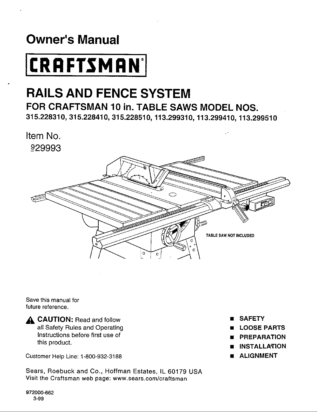
RAILS AND FENCE SYSTEM
FOR CRAFTSMAN 10 in. TABLE SAWS MODEL NOS.
315.228310, 315.228410, 315.228510, 113.299310, 113.299410, 113.299510
Item No.
_929993
Save this manual for
future reference.
_, CAUTION: Read and follow
all Safety Rules and Operating
Instructions before first use of
this product.
Customer Help Line: 1-800-932-3188
Sears, Roebuck and Co., Hoffman Estates, IL 60179 USA
Visit the Craftsman web page: www.sears.com/craftsman
TABLE SAWNOTINCLUDED
• SAFETY
• LOOSE PARTS
• PREPARATION
• INSTALLATION
• ALIGNMENT
972000-662
3-99
Page 2
READ ALL INSTRUCTIONS
• READ THESE INSTRUCTIONS AND THE
INSTRUCTIONS FOR YOUR TABLE SAW
THOROUGHLY before using accessories.
• ALWAYS WEAR SAFETY GLASSES. Everyday
eyeglasses have only impact-resistant lenses;
they are NOT safety glasses.
• ALWAYS DISCONNECT SAW FROM POWER
SUPPLY BEFORE MAKING ADJUSTMENTS
KNOW YOUR POWER TOOL. Read the owner's
manual for the Table Saw carefully. Learn the
saw's applications and limitations as well as the
specific potential hazards related to this tool.
KEEP THE WORK AREA CLEAN. Cluttered
work areas and work benches invite accidents.
OR ADDING ACCESSORIES. Make sure the
switch is off when reconnecting to power supply,
• SAVE THESE INSTRUCTIONS. Refer to them
frequently and use to instruct other users. If you
loan someone this tool, loan them these instruc-
tions also.
DO NOT leave tools or pieces of wood on the
saw while it is in operation.
Look for this symbol to point out important safety precautions. It
means attention.q! Your safety is involved.
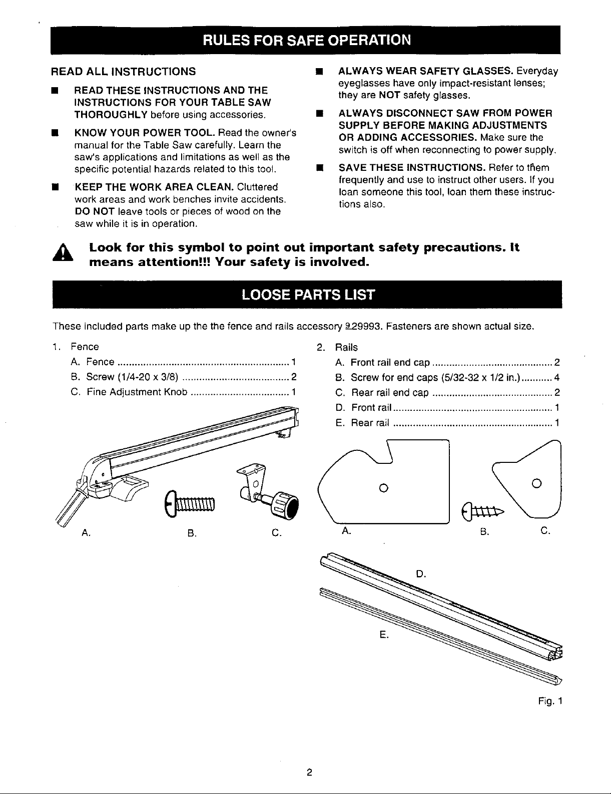
These included parts make up the the fence and rails accessory 9P9993. Fasteners are shown actual size.
1. Fence
A, Fence ............................................................. 1
B. Screw (1/4-20 x 3/8) ...................................... 2
C. Fine Adjustment Knob ................................... 1
A. B. C.
2.
Rails
A. Front rail end cap ........................................... 2
B. Screw for end caps (5/32-32 x 1/2 in.) ........... 4
C, Rear rail end cap ........................................... 2
D. Front rail ......................................................... 1
E. Rear rail ......................................................... 1
O
A. C.
B.
©
Fig. 1
2
Page 3
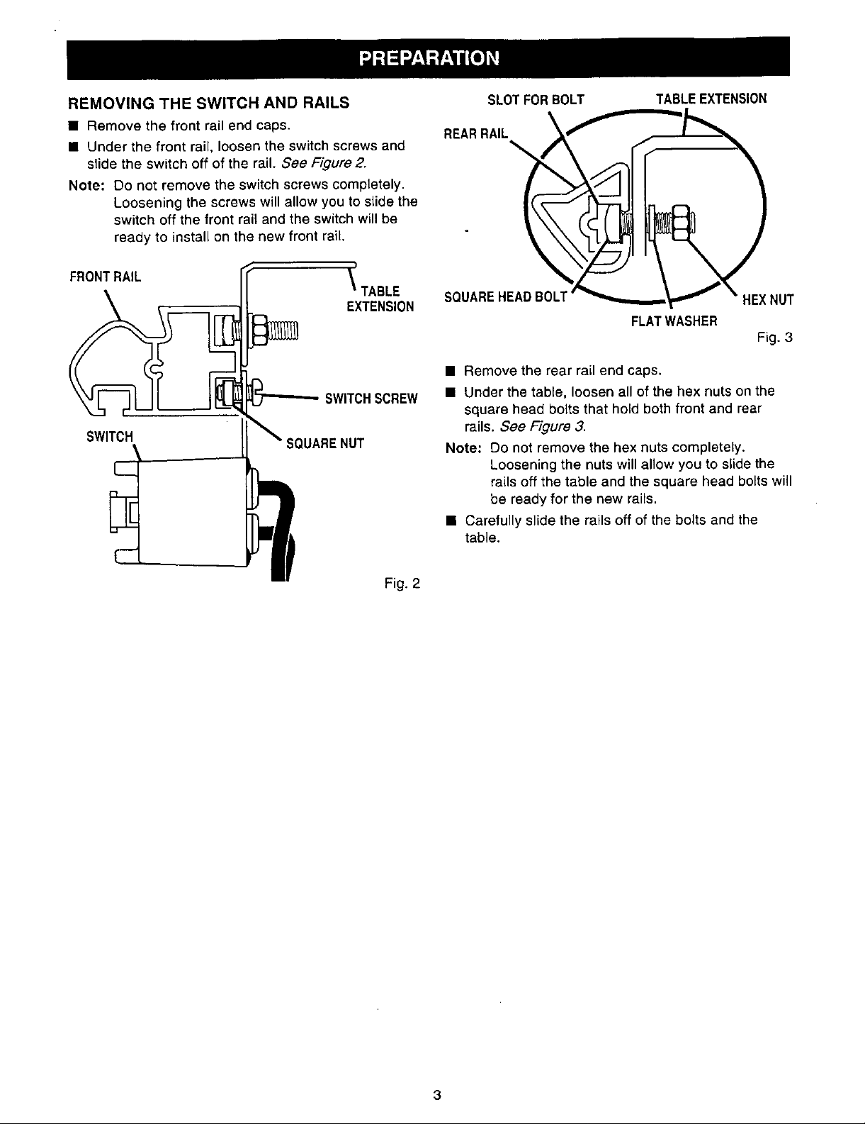
REMOVING THE SWITCH AND RAILS
• Remove the front rail end caps.
• Under the front rail, loosen the switch screws and
slide the switch off of the rail. See Figure 2.
Note: Do not remove the switch screws completely.
Loosening the screws will allow you to slide the
switch off the front rail and the switch will be
ready to install on the new front rail,
SLOTFORBOLT
REARRAIL __
TABLEEXTENSION
FRONTRAIL
SWITCH
L._
_ TABLE
EXTENSION
SWlTCHSCREW
SQUARENUT
Fig. 2
SQUAREHEADBOLT
FLATWASHER
• Remove the rear rail end caps.
• Under the table, loosen all of the hex nuts on the
square head bolts that hold both front and rear
rails. See Figure 3.
Note: Do not remove the hex nuts completely.
Loosening the nuts will allow you to slide the
rails off the table and the square head bolts will
be ready for the new rails.
• Carefully slide the rails off of the bolts and the
table.
HEXNUT
Fig. 3
Page 4

INSTALLING THE REAR RAIL
A'_ WARNING: Front and rear rails must be
carefully aligned to reduce the risk of kickback,
which can cause serious injury.
• From the carton, remove the rear rail and the
following hardware:
Right and left end caps for rear rail
2 screws (5/32-32 x 1/2 in.) for end caps
Note: The square head bolts, washers, and hex nuts
shown at the top of figure 3 should still be on the
table saw. If you mistakenly removed them, put
them back on the table. Do not tighten.
• Carefully slide the rail onto the square head bolts.
SQUAREHEAD
BOLT
• Position rail so that the right hand edge extends
2-1/2 in. beyond the table extension.
Note: Instructions are given from the operator's
position in front of the saw.
• Push the rail against table and tighten each hex
nut with a 12 mm wrench. If the rail jams or does
not slide easily over the bolts, re-align the table
extensions according to the instructions in the table
saw owner's manual.
Note: Make sure there are no gaps between the rail
and edge of table or extensions.
• Put the end caps on the rail ends. Insert the
screws and tighten with a phillips screwdriver.
FLAT WASHER
HEXNUT
SCREW
Fig. 4
4
Page 5

INSTALLING THE FRONT RAIL
• Locate the front rail and the following hardware:
Right and left end caps for front rail
2 screws (5/32-32 x 1/2 in.) for end caps
• Set aside the end caps and two screws until the
switch has been installed.
Note: The square head bolts, washers, and hex nuts
shown at the bottom of figure 6 should still be
on the table saw. If you mistakenly removed
them, put them back on the table. Do not
tighten.
• The back of the rail has two slots. See Figure
Carefully slide the upper slot over the bolts.
(Bottom slot is for switch.)
• Align the rail left to right - Match the 7-1/8 in. mark
on the right scale to the right edge of the saw base
(main table). See Figure 8.
• Snug the rail against table. Finger-tighten each nut
on the table and extensions.
RAILSLOT
SAWTABLE
HEXNUT
SWITCHSLOT
Fig. 7
TABLETOPVIEWEDFROMABOVE
TABLE
EXTENSION
SCALE
FRONTRAIL
HEIGHT
HANDWHEEL
SQUAREHEAD
SCALE
\.
FRONTRAIL 7-1/8in,MARKRIGHTSCALE
Fig. 8
FLATWASHER
HEXNUT
Fig. 6
Page 6

• Insert the two remaining pan head screws into
holes in the fine adjustment knob bracket.
• Attach the fine adjustment knob bracket to the
bottom of the fence head on the right or the left
side of the fence handle. Securely tighten the two
screws.
BRACKET
SCREWS _ _
Fig. 9
FRONTRAIL
SWITCH
ASSEMBLY
P
\
TABLE
EXTENSION
SWITCHSCREW
Fig. 10
MOUNTING THE SWITCH
• Locate the switch assembly, The fasteners should
still be attached.
Note: If the fasteners were removed from the switch,
see instructions in your table saw Owner's
Manual for mounting the switch or refer to
Figure 10.
• Holding the switch to the front, insert and slide the
two square nuts into the lower slot of the front rail.
_I, WARNING: Place the switch out of the immedi-
ate work area to avoid accidentally turning it off
during operation.
• Slide the switch assembly to a convenient position,
leaving ample clearance for the handwheel.
Tighten securely with a screwdriver.
• Attach the front rail end caps and screws with a
phillips screw driver. See Figure 11.
ENDCAP
SCREW
Fig. 11
Page 7

ALIGNING THE RIP FENCE AND FRONT RAIL •
The rip fence scale indicator is installed on the right
side of the rip fence but can be removed and rein-
stalled on the left side if needed. If a cutting operation •
requires placing the rip fence on the left side of the
blade, and you find relocating the indicator necessary,
simply unscrew and re-attach it.
• Hook the back of the rip fence over the rear rail. •
See Figure 12. Lowper the front of the rip fence
into the groove on the front rail. See Figure 13.
• Slide the rip fence back and forth. It should move
freely with about 1/16 in. clearance below the rip
fence. If it doesn't, loosen the nuts holding the front
rail and adjust the rail up or down. See Figure 6.
RIPFENCE
HOOKOVER
REARRAIL
HERE
Remove the rip fence and repeat on the other side
of the blade. When the fence rides smoothly,
tighten all rail hex nuts with a 12 mm wrench.
Push in the micro-adjust knob and turn it. The gear
on the shaft assembly will engage the rack teeth
on the rack and will move the fence assembly left
or right.
Push down on the rip fence handle to lock the rip
fence in place.
TOINSTALL
INDICATOR
ONLEFT
SIDE
REARRAIL
Fig. 12
RIP FENCEHANDLE
Fig. 13
Page 8

CHECKING RIP FENCE AND.
BLADE ALIGNMENT
The rip fence is self-aligning but should be checked
before first use.
_. WARNING: Failure to align the rip fence to the
blade can cause jams and kickback, resulting in
serious personal injury.
• Slide the rip fence to the miter gauge groove,
which is parallel to blade. Do not lock the rip fence.
• Place a framing square against the blade, with the
long end under the rip fence at the front. See
Figure 14. Note the distance.
• Move the square to the back and measure the
length from other end of the fence. See Figure 15.
• Ifthe distances are different, loosen the four
screws around the rip fence handle with a 6 mm
hex key. Alternate the order (remove the screw
opposite, not next to the first one). See Figure 16.
• Hold the fence handle against the front rail and
align the rip fence with the blade.
• Retighten the screws in alternating order and
check the alignment.
• Repeat until the rip fence is aligned.
MITERGAUGEGROOVE FRAMING
SQUARE
ADJUSTMENTSCREWS
Fig. 15
RIPFENCE
MITERGAUGEGROOVE
BLADE RIPFENCE
MITERGAUGE
GROOVE
Fig. 14
ADJUSTMENT
SCREWS(4)
RIPFENCE
HANDLE
Fig. 16
Note: To insure proper self alignment when position-
ing rip fence, push sides of scale indicator
housing against front rail before locking rip
fence handle.
8
 Loading...