

Craftsman 113.29884 Owner's Manual
Save This Manual For
Future Reference
MODEL NO.
113=29884
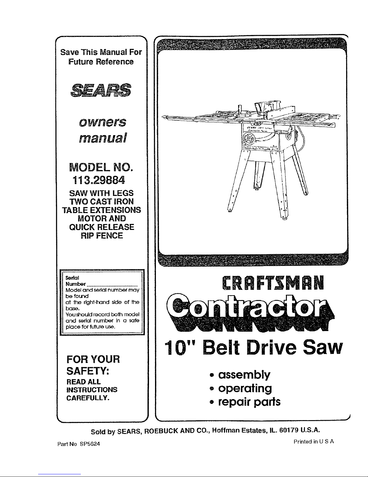
SAW WITH LEGS
TWO CAST IRON
TABLE EXTENSIONS
MOTOR AND
QUICK RELEASE
RIP FENCE
Sedal
Number
Model and serlQInum_:x_rmay
be fotr_
at 1he rlghf-I'_nd side of the
bose.
You should r_ord both model
and sedal number In a safe
place for future use.
FOR YOUR
SAFETY:
READ ALL
INSTRUCTIONS
CAREFULLY.
CRRFTSMRH
10" Belt Drive Saw
• assembly
= operating
• repair parts
_,, J _.
Sold by SEARS, ROEBUCK AND CO., Hoffman Estates, IL. 60179 U.S.A.
Part No SP5624 Printed in U S A
J
BI
if within one year from the data of purchase, this CraftsmenTable Saw fails due to a defect in
WARRANTY SERVICE IS AVAILABLE BY SIMPLY CONTACTING THE NEAREST SEARS SERVICE
CENTER/DEPARTMENT THROUGHOUT THE UNITED STATES.
THIS WARRANTY APPLIES ONLY WHRLE THIS PRODUCTIS USED IN THE UNITED STATES.
This warranty gives you specific legal rights, and you may also have other rights which vary from
state to sttata.
SEARS, ROEBUCK AND CO., D/817 WA Hoffman Estates, iL 60179
SAFETY iNSTRUCTiONS FOR TABLE SAW
Safety is a combination of common sense, staying alert
and knowing how your table saw works. Read this
manual to understand this saw.
BEFORE USING THE SAW
WARNING: To avoid mistakes that could cause
serious, permanent Injury, do not plug the saw in
until the following steps have been satisfactorily
completed.
1. Assembly and Alignment (See pages 13 - 34).
2. Learn the use and function of the ON-OFF Switch,
Guard, Spreader, Anti-Kickbackdevice, MiterGauge,
Fence, Table Insert and Blade Elevation and Bevel
Controls. (See page 35)
3. Review and understanding of all safety instructions
and operating procedures in this manual.
4. Review of the maintenance methods for this saw.
4. GROUND THE SAW- This saw has an approved 3-
conductor cord and a 3-prong grounding type plug.
The plug fitsgroundingtype outlets designed for 120
volt 15 amp circuits. The green conductor inthe cord
isthe groundingwire. To avoid electrocution,NEVER
connect the green wire to a live terminal.
5. To avoid injuryfrom electrical shock, make sure your
fingers do not touch the plug's metal prongs when
plugging in or unplugging the saw.
6. To avoid back injury, get help or use recommended
casterswhen youneed to movethe saw. Always get
help if you need to il_ the saw. Holdthe saw closeto
yourbody. Bend your knees so you can liftwithyour
legs, not your back.
7. NEVER STAND ON TOOL. Serious injury could
occur ifthe tool tips or you accidentally hitthe cutting
tool. Do not store anything above or near the tool
where anyone mightstand onthe toolto reach them.
Read theDANGER labelfound onthe frontof the saw as BEFORE EACH USE:
shown below.
WHEN INSTALLING OR MOVING THE SAW
1. AVOID DANGEROUS ENVIRONMENT. Use the
saw in a dry place protected from rain. Keep work
area well lighted.
2_To avoid injuryfrom unexpectedsaw movement:
A. Put the saw on a firm level surface where there is
B. Support the saw sothe table islevel and the saw
does not rock.
C. Bolt the saw to the floor if it tends to slip walk, or
slideduring normal use.
D. When using table extensions over 24 inches wide
on any side of the saw, boltthe saw to the floor or
prop up the outer end of the extension from tLa
floor to keep the saw from tipping.
3. Put the saw where neither operators nor bystanders
must stand in line with the saw blade.
I _DANGER
1, Read manual before using saw 4. Keep blade guard down and m 7. When ripping_ use push stickwhen
2. Wear safety goggles that meet pla_e for through cbts. fence is set 2 _nc_es or more from
ANSt ZE_Trl standards, 5 Do not do freehand cuts, blade.
3 DO not reach around Or over saw 6, Keep h_5 out of path of s3w B. Know how t_ reduce the risk of
b_;_des bJade _c_back See in_ructtons for flppli'Ig
1. Inspect your saw.
A. To avoid injuryfrom accidental starting, unplugthe
saw, turnthe switchoffand remove the switchkey
before raising or removing the Guard, changing
the cutting tool, changing the setup or adjusting
anything.
B. Check for alignment of moving parts, binding of
moving parts, breakage of parts, mounting, and
any other condit_ns that may affect the way it
works. If any partis missing, bent, or broken inany
way, or any electrical parts don't work properly,
turn the saw off and unplug the saw.
C. Replace damaged, missing, orfailed parts before
using the saw again.
D. Use the Sawblade Guard, Spreader, and Anti-
Kickback Pawlsfor anythru-sawing (whenever the
blade comes through the top of the workplace).
Make surethe Pawls work properly. Make sure the
Spreader is in line with the sawblade.
!
g. When ripping, use push bI_CK ana t 0. Turn power Off and wait for blade]_
aux_Fary fence when fence _s set _ stop befor_ _l_jtJStl_lg ot
I
between 2 and 2 inches from _ervi¢lng
blade Do not make r_ cu_s
narrc_ver tr_an _/_ inch.
E. REMOVEADJUSTING KEYSANDWRENCHES.
Form habit of checking for and removing keys and
adjusting wrenches from tool before turning it on.
F, To avoid injury from jams, slips or thrown pieces
(kickback and throwback):
1. USE ONLY "RECOMMENDED ACCESSO-
RIES" (See page 58). Follow the instructions
that come with the accessories. The use of
improper accessories may cause risk of injury to
persons.
2. Choose the right blade or cutting accessory for
the material and the type of cutting you plan to
do.
3. Never use grinding wheels, abrasive cut-off
wheels, friction wheels (metal slitting blades)
wire wheels or buffing wheel. Theycan fly apart
explosively.
4. Choose and inspect your cutting tool carefully.
a. To avoidcuttingtoolfailure andthrown shrap-
nel (broken pieces of blade), use only 10" or
smaller blades or other cutting tools marked
for speeds of 3450 rpm or higher.
b. Always use unbroken, balanced blades
designed to fit thissaw's 5/8 inch arbor.
c. When thru-sawing (making cuts where the
blade comes through the workpiece top),
always use a 10 inch diameter blade. This
keeps the spreader in closest to the blade.
d. Do not overtighten arbor nut. Use arbor
wrenches to "snug" it securely.
e. Useonlysharpbladeswith properly setteeth.
Consult aprofessional blade sharpenerwhen
in doubt,
f. Keep blades clean of gum and resin.
5. Adjust table inserts flush with the table lop.
NEVER use the saw without the proper insert.
6. Make sure all clamps and locks are tight and no
parts have any excessive play.
2. Keep work area clean
A Cluttered areas and benches invite accidents.
Floor must not be slippery from wax or sawdust.
B. To avoid burns or other fire damage, never use the
saw near flammable liquids, vapors or gases.
C. To avoid injury, don't do layout, assembly, or setup
work on the table while the blade is spinning. It
could cut or throw anything hitting the blade.
Plan ahead to protect your eyes, hands, face,
ears.
3. Plan yourwork
A. USE THE RIGHT TOOL - Don't force tool or
attachment to do a job it was not designed for.
B. Dress for safety:
1. Do not wear loose clothing, gloves, neckties or
jewelry (rings, wristwatches). They can get
caught and draw you into moving parts.
2. Wear nonslip footwear.
3. Tie back long hair.
4. Roll long sleeves above the elbow.
5. Noise levels vary widely. To avoid possible
hearing damage, wear ear plugs or muffs when
using saw for long periods of lime.
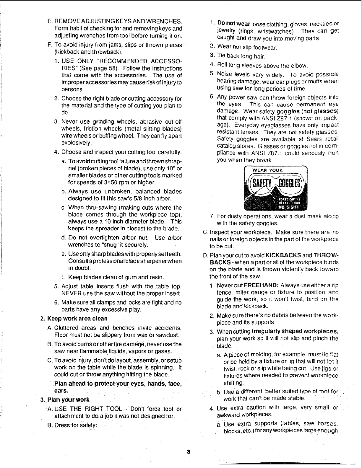
6. Any power saw can throw foreign objects into
the eyes. This can cause permanent eye
damage. Wear safety goggles (not glasses)
that comply with ANSI Z87.1 (shown on pack-
age). Everyday eyeglasses have only impact
resistant lenses. They are not safety glasses.
Safety goggles are available at Sears retail
catalog stores. Glasses or goggles not in com-
pliance with ANSI Z87.1 could seriously hurt
you when they break.
WEAR YOUR
7. For dusty operations, wear a dust mask along
with the safety goggles.
C. Inspect your workpiece. Make sure there are no
nails or foreign objects in the part of the workpiece
to be cut.
D. Plan your cut to avoid KICKBACKS and THROW-
BACKS - when a part or all of the workpiece binds
on the blade and is thrown violently back toward
the front of the saw.
1. Nevercut FREEHAND: Always use eithera rip
fence, miter gauge or fixture to position ane
guide the work, so it won't twist bind on the
blade and kickback.
2. Make sure there's no debris between the work-
piece and its supports.
3. When cutting irregularly shaped workpieces,
plan your work so it wilt not slip and pinch the
blade:
a. A piece of molding, for example, must _ieflat
or be held by a fixture or jig that will not let it
twist rock or slip while being cut. Use jigs or
fixtures where needed to prevent workpiece
shifting.
b. Use a different, better suited type of tool for
work that can't be made stable.
4. Use extra caution with large, very small or
awkward workpieces:
a. Use extra supports (tables, saw horses.
blocks, etc.] for anyworkpieces large enough
to tip when not held down to the table top.
NEVER use another person as a substitute
for atable extension, oras additional support
for a workpiece that is longer or wider than
the basic saw table, or to help feed, support
or pull the workpiece.
b. Never confinethe piece being cutoff, that is,
thepieceNOTagainstthe Fence,MiterGauge
or fixture. Never hold it, clamp it, touch it, or
use length stops against it. Itmustbe freeto
move. Ifconfined, itcouldget wedged against
the blade and cause a kickback or throw-
back.
c. Nevercut morethan one workpiece at atime.
d. Never turn your table saw "ON"before clear-
ing everything except the workpiece and
related support devices off the table.
4. Plan thewayyou will pushtheworkplecathrough.
A. NEVER pull the workpiece through. Start and
finish thecut from the front of the table saw.
B. NEVER put your fingers or hands in the path of
the sawblade or other cutting tool.
C. NEVER reach Inback ofthe cutUngtoolwith either
hand to hold clown or support the workpiece,
remove wood scraps, orfor any other reason.
D. Avoid hand positions where a sudden slip could
cause fingers or hand to move intoa sawblade or
other cutting tool.
E. DON'T OVERREACH. Always keep good footing
and balance.
F. Push the workpiece against the rotation of the
blade. NEVER feed material intothe cutting tool
from the rear of the saw,
G,Always push the workpiece all the way past the
sawblade.
H.As muchas possible, keep your face and body to
one side ofthe sawblade,out of linewith a possible
kickback or throwback.
I. NEVERtumthe saw"ON"before cleadngthetable
of all tools, wood scraps, etc., except the work-
piece and related feed or support devices for the
cut planned.
J. AVOID ACCIDENTAL STARTING - Make sure
switch is "OFF" before plugging saw in.
WHENEVER SAW BLADE IS SPINNING
WARNING: Don't let familiarity (gained from fre-
quent use of your table saw) cause a careless
mistake. Always remember that a careless frac-
tion of a second is enough to cause a severe
injury.
1. Before actually cutting with the saw, watch it while it
runsfor a short while. Ifit makes an unfamiliar noise
or vJ_oratesa lot,stop immediately. Turn the saw off.
Unplug thesaw. Do not restart until finding and fixing
the problem.
2. Make sure the top of the arbor or cutting toot tu ms
toward the front of the saw.
3. Set the cutting tool as low as possible for the cut
you're planning.
4. KEEP CHILDREN AWAY. Ailvisitors should be kept
asale distancefmmwork. Make surebystanders are
clear ofthe saw and workpiece.
5. Let the blade reachfull speed before cutting.
6. DON'T FORCE TOOL. It will do the job better and
safer at itsdesigned rate. Feed the workpiece intothe
blade only fast enough to let it cut without bogging
down or binding.
7. Beforefreeing any jammed material:
A. -rum switch "OFF".
B. Unplug the saw.
C. Wait for all moving parts to stop.
D. Check blade, Spreader and Fence for proper align-
ment before starting, again.
8. To avoid throwback of cut off pieces;
A. Use the Guard assembly.
B. To remove loose pieces beneath ortrapped inside
the guard:
1. Turn saw "OFF".
2. Remove switch key.
3. Wait for blade tostop before liftingthe Guard.
additional instructions for
RiP TYPE CUTS
1. NEVER use the Miter Gauge when ripping.
2. Use a Push Stick whenever the fence is 2 or more
inches from the blade. When thru=sawing, use an
Auxiliary Fence and Push Block whenever the Fence
mustbe between 1/2 and 2 inchesofthe blade. Never
thru-saw ripcutsnarrower than 1/2 inch. (See"BASIC
SAW OPERATION - USING THE RiP FENCE" sec-
tion.)
3. Never rip anything shorter than 10" long.
4. When using a Push Stick or Push Block, the trailing
end of the board must be square. A Push Stick or
Block against an uneven end could slip offor push the
work away from the Fence.
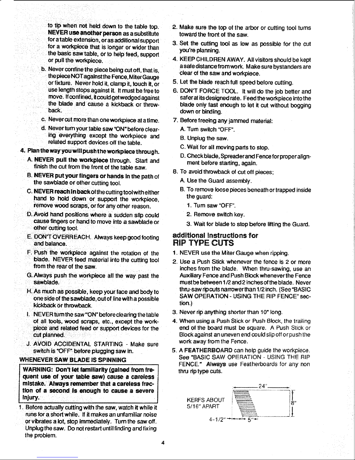
5. A FEATHERSOARD can help guide the workpiece.
See "BASIC SAW OPERATION - USING THE RiP
FENCE." Always use Featherboards for any non
thru rip type cuts.
24"
KERFS ABOUT
5/16" APART
4-112 '''-'_--'_ 5'""
BEFORESTARllNG
1. To avoid kickbacks and slips into the blade, make
sure the Rip Fence is parallel to the sawblade.
2. Before thru-sawing, check the Anti-Kickback Pawls.
(See "BASIC SAW OPERATION - USING THE RIP
FENCE.") The Pawls must stop a kickback once it
has started. Replace or sharpen Anti-Kickback Pawls
when points become due
3. Plastic and composition (like hardboard) materials
may be cut on your saw. However, since these are
usually quite hard and slippery, the Anti-Kickback
Pawls may not stop a kickback. Therefore, be espe-
cially careful in your set-up and cutting procedures.
WHILE CUTTING
1. To avoid kickbacks and slips into the blade, always
push forward onthe section of theworkpiece between
the saw blade and the Rip Fence. Never pushforward
on the piece being cut off.
3. Use jigsorfixtures to help hold any piece too sina!! to
extend across the full lengthof the Miter Gauge face
during the cut. This lets you propedy hold the Miter
Gauge and workpiece and helps keep your hands
away from the blade. (See page 37.)
WHgLE CUTTING
1. To avoid blade contact, always hold the Miter Gauge
as shown inthe "BASIC SAW OPERATIONS - US-
iNG THE MITER GAUGE."
BEFORE LEAVDNG THE SAW
1. Turn the saw off.
2.
3.
Wait for blade to stop spinning,
Makeworkshopchild-proof. Lock the shop. Discon-
nect master switches. Remove the yellow Switch
Key. Store it away from children and others not
qualified to use the tool.
4. Unplug the saw.
additional instructions for
CROSS CUT TYPE CUTS
BEFORE STARTING
1. NEVER use the Rip Fence when crossc:£ting.
2. An auxiliary wood facing attached to the Miter Gauge
can help prevent workpiece twisting and throwbacks.
Attach it to the holes provided. Make the facing long
enough and big enough to support your work. Make
sure, however, it will not interfere withthe Sawblade
Guard.
glossary of terms for woodworking
Anti-Kickback Pawts {AKP)
Device which, when properly maintained, isdesigned to
stop the workpiece from being kicked back at the opera-
tor during dpping operation.
Arbor
The shaft on which a cutting tool is mounted.
Crosscut
A cutting or shaping operation made across the width of
the workpiece.
Dado
Anon through cut which produces a square ._;ided notch
or trough inthe workpiece.
Featherboard
A device which can help guide workpieces during rip
type operation.
Freehand
Performing a cut without using a Fence, Miter Gauge,
fixture, hold down or other proper device to keep the
workpiece from twisting during the cut.
Gum
A sticky, sap based residuefrom wood products.
Heel
Misalignment of the blade.
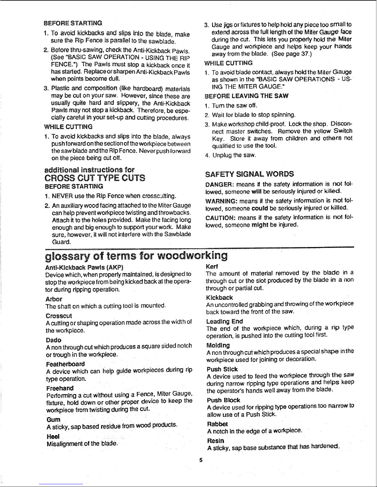
SAFETY SIGNAL WORDS
DANGER: means if the safety information is not fol-
lowed, someone wig be seriously injured or killed.
WARNING: means if the safety information is not fol-
lowed, someone could be seriously injured or killed.
CAUTION: means if the safety information is not fo!-
lowed, someone might be injured.
Leading End
The end of the workpiece which, during a rip type
operation, is pushed intothe cutting tool first.
Meldlng
A non through cut which produces a special shape inthe
workpiece used for ioining or decoration.
Push Stick
A device used to feed the workpiece through the saw
during narrow ripping type operations and helps keep
the operator's hands well away from the blade.
Push Block
A device used for rippingtype operations |oo narrow to
allow use of a Push Stick.
Rabbet
A notch inthe edge of a workpiece.
Resin
A sticky, sap base substance that has hardened,
Kerr
The amount of material removed by the blade in a
through cut or the slot producedby the blade in a non
through or partial cut.
Kickback
An uncontrolled grabbing and throwing of the workpiece
back toward the front of the saw.
glossary of terms for woodworking
Ripping
A cutting operation along the length of the workpiece.
Revolutions Per Minute (RPM)
Thenumber of turns completed by a spinning object in
one minute.
Sawblade Path
Theareaof theworkpiece ortable topdirectlyin line with
the part of the workplece which willbe or has been, cut
bythe blade.
Set
Thedistancethat theti 3of thesawblade tooth is bent (or
set) outward from the face of the blade.
ThrOw-Back
Throwing of pieces in a manner similarto a kickback.
Thru-Sawlng
Any cutting operation where the blade extends com-
pletely though the thickness of the workpiece.
Trailing End
The wod_oiece end last cut by the blade in a ripping
operation.
Workpiece
The itemon which the cutting operation is being done,
The sudaces of a workpiece are commonly referred to
as faces, ends, and edges.
MOTOR SPECiFiCATiONS AND ELECTRICAL REQUIREMENTS
MOTOR SPECIFICAT|ONS
Thissaw isdesigned to use a 3450 RPM motor only. Do
not use any rnotorthat runs faster than 3450 RPM. The
A-C motorused inthis saw isa capacitor start, capacitor
run, non-reversible type motor, it is wired at the factory
for operation on 120v AC, 60 Hz., alternating curre_. It
may be converted to operate on 240v AC. Listedbelow
are the motor specifications.
t WARNING: Do riot use blower or washing ma-
chine or any motor with an automatic reset over-
load protector. They can start up by themselves
and you could get Injured.
CONNECTING TO POWER SOURCE
OUTLET
This saw must be grounded while in use to protect the
operator from electrical shock.
WARNING: Damaged power cords can cause
shock or fires, if the power cord is worn, cut or
damaged in any way, have it replaced immedi-
ately.
WARNING: Electric shockcan kill. Not all ouUets
are properly grounded, if you are not sure that
your outlet is properly grounded, have it checked
by a qualified electrician.
3-PRONG PLUG
GROUNDING PRONG
GROUNDED
3-PRONG OUTLET
WARNING: To avoid electrical shock, do not
permit fingers to touch the terminals o! the plug,
when installing or removing the plug to or from
the outlet.
WARNING: Failure toproperly ground this power
tool can cause electrocution or serious shock,
particularly when used in damp locations, or near
metal plumbing, lifshocked, your reaction could
cause your hands to hit the cutting tool.
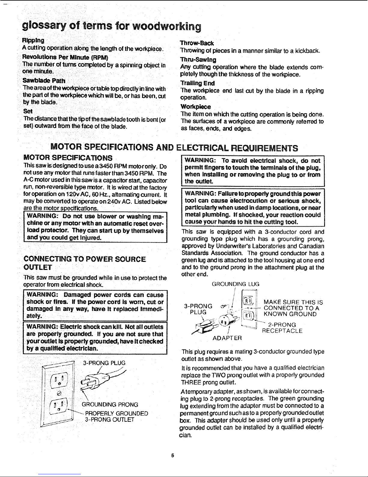
This saw is equipped with a 3-conductor cord and
grounding type plug which has a grounding prong,
approved by UndePJvriter'sLaboratories and Canadian
Standards Association. The ground conductor has a
green lugand is attached tothe tool housing at one end
and to the ground prong inthe attachment plug at the
other end.
3-PRONG ¢P;
GROUNDING LUG
[ ,ii
ADAPTER
MAKE SURE THIS IS
CONNECTED TO A
KNOWN GROUND
_ 2-PRONG
RECEPTACLE
This plug requires a mating 3-conductor grounded type
outlet as shown above.
It is recommended that you have a qualified electrician
replace the TWO prong outlet with a properly grounded
THREE prong outlet.
Atemporary adapter, as shown, isavailable for connect-
ing plug to 2-prong receptacles. The green grounding
lug extending from the adapter must be connected to a
permanent groundsuch aslo a properly grounded outlet
box. This adapter should be used only until a properly
grounded outlet can be installed by a qualified electri-
cian.
WARNING: Avoid eJectric shock, if the outlet you
are piannlng to use for this saw Is of the two prong
type, DO NOT REMOVE OR ALTER THE GROUND-
iNG PRONG INANY MANNER. Use an adapter, as
shown, and always connect the grounding lug to
a known ground, such as to a properly grounded
outlet box, Not aJll o_iet boxes are properly
grounded° If you are not sure the outlet box is
properly grounded, have It checked by a quaJified
electrlclan.
CHANGING MOTOR VOLTAGE
WARNING: Eiectric shock can kill.To avold
shock, never connect plug to power source outUet
until a_l assembly slops are completed. Unplug
saw before making or changing any connections.
1. Connections for 120v AC Operation
a. Foroperation on 120 volts, the bRackpower lead is
connected to spade terminal beside copper post.
The white power lead is connected to spade termi-
nal beside silver post. Thetwo movable links must
be in position shown in Figure 1, The red motor
lead is connected to terminal "B."
b. The movable links pivotonthe centermost screws.
After linkshave been correctly positioned, be sure
to tighten these screws to insure agood electricaI
connection.
120 VOLT CONNECTION
COPPER POST __-J_"4..\_
/r---- ....
BLACK POWER LEAD --n_ GREEN
GROUND SCREW
SPADE TERMINALS_. t _ .LINKS IN THIS
WHITE :OL_ER LEAD ?_ POSITION
B RED
_i ER POST
FIGURE 1
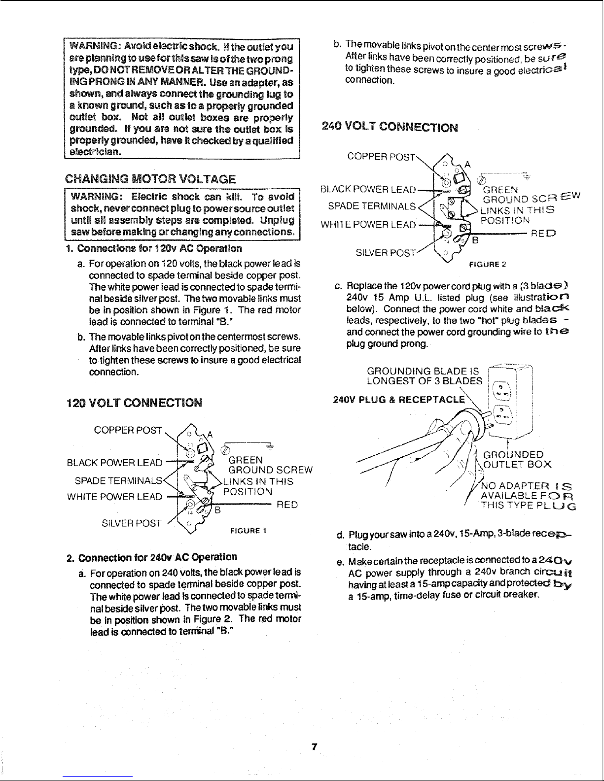
2. Connection for 240v AC Operation
a. Foroperation on 240 volts, the black power lead is
connected to spade terminal beside copper post.
The white power lead isconnected to spade termi-
nalbeside silverpost. The two movable links must
be in position shown in Figure 2. The red motor
lead is connected to terminal "B."
b. The movable linkspivot onthecenter most screv_,_ -
After links have been correctly positioned, be SL_r_
to tighten these screws to insure a good etectdc _
connection.
240 VOLT CONNECTION
COPPER
BLACK POWE
SPADE TERMINALS,
WHITE POWER
SILVER
GREEN
GROUND SCR E_.W
IN THIS
POSITION
RED
B
FIGURE 2
c. Replace the !20v power cord plug with a (3 blade)
240v 15 Amp U.L listed plug (see illustration
below). Connect the power cord white and black
leads, respectively, to the two "hot" plug blades -
and connect the power cord grounding wire to th_
plug ground prong.
GROUNDING BLADE tS -_..... J
LONGEST OF 3 BLADES ,--
24ov PLUG&RECEPTACLE i '--_ i
#
GROUNDED
OUTLET BOX
ADAPTEF{ I S
AVAILABLE FO F_
THIS TYPE PLUG
d. Plugyoursaw intoa 240v, 15-Amp, 3-blade receiz_-
tacle.
e, Make cerlain the receptacle isconnected to a24(3Pv
AC power supply through a 240v branch circ:_ilt
having atleast a15-ampcapacity and protected by
a 15-amp, time-delay fuse or circuit breaker.
7
Motor Thermal Overload Protector
IMPORTANT: To avoid motor damage, this motor should
be blown out orvacuumed frequently to prevent sawdust
buildupwhich will interfere with normal motor ventilation.
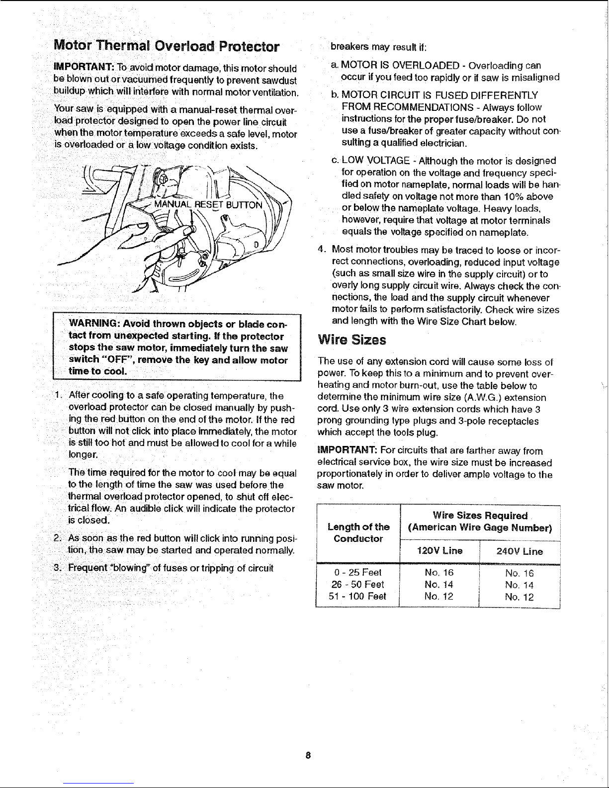
Your saw is equipped with a manual-reset thermal over-
load protector designed to open the power line circuit
when the motor temperature exceeds a safe level, motor
is overloaded or a low voltage condition exists.
WARNING: Avoid thrown objects or blade con.
tact from unexpected starting, if the protector
stops the saw motor, immediately turn the saw
switch "OFF", remove the key and allow motor
time to cool.
1. After cooling to a safe operating temperature, the
overload protector can be closed manually by push-
ing the red button on the end of the motor. If the red
button will not click into place immediately, the motor
is still too hot and must be allowed to cool for a while
longer.
The time required for the motor to cool may be equal
to the length of time the saw was used before the
thermal overload protector opened, to shut of! elec-
trical flow, An audible click will indicate the protector
is closed.
2_ As soon as the red button will click into running posi-
tion. the saw may be started and operated normally.
3. Frequent "blowing" of fuses or tripping of circuit
breakers may result if:
a. MOTOR IS OVERLOADED - Overloading can
occur ifyou feed too rapidly or ifsaw is misaligned
b. MOTOR CIRCUIT IS FUSED DIFFERENTLY
FROM RECOMMENDATIONS - Always follow
instructions for the proper fuse/breaker, Do not
use a fuse/breaker of greater capacity without con.
suiting a qualified electrician
c. LOW VOLTAGE - Although the motor is designed
for operation on the voltage and frequency speci-
fied on motor nameplate, normal loads will be han-
died safety on voltage not more than 10% above
or below the nameplate voltage. Heavy loads.
however, require that voltage at motor terminals
equals the voltage specified on nameplate.
4. Most motor troubles may be traced to loose or incor-
rect connections, overloading, reduced input voltage
(such as small size wire inthe supply circuit) or to
overly long supply circuit wire. Always check the con-
nections, the load and the supply circuit whenever
motor fails to perform satisfactorily. Check wire sizes
and length with the Wire Size Chart below.
Wire Sizes
The use of any extension cord will cause some loss of
power. To keep this to a minimum and to prevent over-
heating and motor burn-out, use the table below to
determine the minimum wire size (A.W.G.] extension
cord. Use only 3 wire extension cords which have 3
prong grounding type plugs and 3-pole receptacles
which accept the tools plug.
iMPORTANT: For circuits that are farther away from
electrical service box. the wire size must be increased
proportionately in order to deliver ample voltage to the
saw motor.
Length of the
Conductor
Wire Sizes Required
(American Wire Gage Number)
12(}V Line 240V Line
0 - 25 Feet No. 16 No. ! 6
26 - 50 Feet No. t4 No 14
51 - 100 Feet _j. No. 12 1 No. 12 __j
CONTENTS
Warranty .................................................................... 2
Safety instructions for Table Saw .......................... 2
Additional Instructions for Rip Type Cuts ............... 4
Additiona_ Instructions for Cross Cut Type Cuts ...5
Glossary of Terms for Woodworking ..................... 5
Motor Specifications and
Electrical Requirements ...................................... 6
Motor Specifications ............................................. 6
Changing Motor Voltage ........................................ 7
Motor Thermal Overload Protector ........................ 8
Wire Sizes .............................................................. 8
Unpacking and Checking Contents ........................ 9
Tools Needed ......................................................... 9
List of Loose Pads ............................................... 10
AssembSy ................................................................ 13
installing Handwheels .......................................... 13
Checking Table Insed ......................................... 13
Checking Blade Squareness to Table ................. 14
Assembling Steel Legs ........................................ 14
Mounting Saw ...................................................... ! 5
Attaching and Assembling Table Extensions ....... 16
Mounting Switch .................................................. 17
installing Right Front Rip Fence
Guide Bar ........................................................ 17
installingLeft Front Rip Fence
Guide Bar ........................................................ 18
Installing Rear Rip Fence Guide Bars .................. 19
Adjusting Rip Fence Guide Bars .......................... 21
Assembling Rip Fence ......................................... 24
Rip Fence Self Aligning Pad Adjustment ............ 25
Rip Fence Lock Lever Adjustment ....................... 26
Rip Fence Alignment Adjustment ........................ 26
Installing Measuring Tapes .................................. 27
Installing Blade Guard ......................................... 29
Positioning Motor on Motor Mounting Base ......... 31
Mounting the Motor .............................................. 32
Installing Belt Guard ............................................. 33
Motor Connections ............................................... 35
Plugging in Motor ................................................. 35
Getting to Know Your Saw .................................... 36
On-Off Switch ....................................................... 36
Elevation Handwheel ........................................... 37
Tilt Handwheel ..................................................... 37
Tilt Lock Handle ................................................... 37
Rip Fence ............................................................. 37
Miter Gauge ......................................................... 3-7
BBade Guard ......................................................... 37"
"]'able Insert ........................................................... 3"7
Removing and Instal{ing Sawblade .....................
Exact-I-Cut ...................................
Micro-Adjust Rip Fence ....................................... 3._;-_
Basic Saw Operation .............................................
Work Helpers ....................................................... 3 g
Push Stick and Push Block .............................. 3_°J
Auxiliary Fence/Work Support ......................... 4.0
Auxiliary Panel/Work Support .......................... z$O
Safety Instructions for Basic Saw Operations ....
Using the Miter Gauge ......................................
Crosscutting .....................................................
Repetitive Cutting ............................................ 4_-_
Miter Cutting ....................................................
Bevel Crosscutting ...........................................
Compound Mfter Cutting .................................. 45
Using the R_pFence ..........................................
Ripping ............................................................ 46
Bevel Ripping Narrow Work ............................ 4.6
Using Featherboards for Thru Sawing ............. 4-7
Resawing ......................................................... 49
Cutting Panels ................................................. 50
Using Featherboards for Non Thru-Sawing ..... 50
Rabbeting ............................................................ 5 1
P_oughing and Molding ........................................ 53
Dadoing ................................................................ 52
Molding Cutting .................................................... 52
Adjustments ...........................................................
Miter Gauge ......................................................... 53
Heeling Adjustment or Parallelism of Sawbtade
to Miter Gauge Groove .................................... 55
Blade Tilt, or Squareness of Blade to Table ........ 55
90° Position ..................................................... 55
45° Position ...................................................... 56
Tilt Mechanism ..................................................... 5-7
Maintenance ........................................................... 57
Lubrication ..............................................................
Recommended Accessories ................................. 5_
Trouble Shooting ................................................... 59
General ................................................................ 59
Motor .................................................................... 59
Repair Parts ............................................................ 62
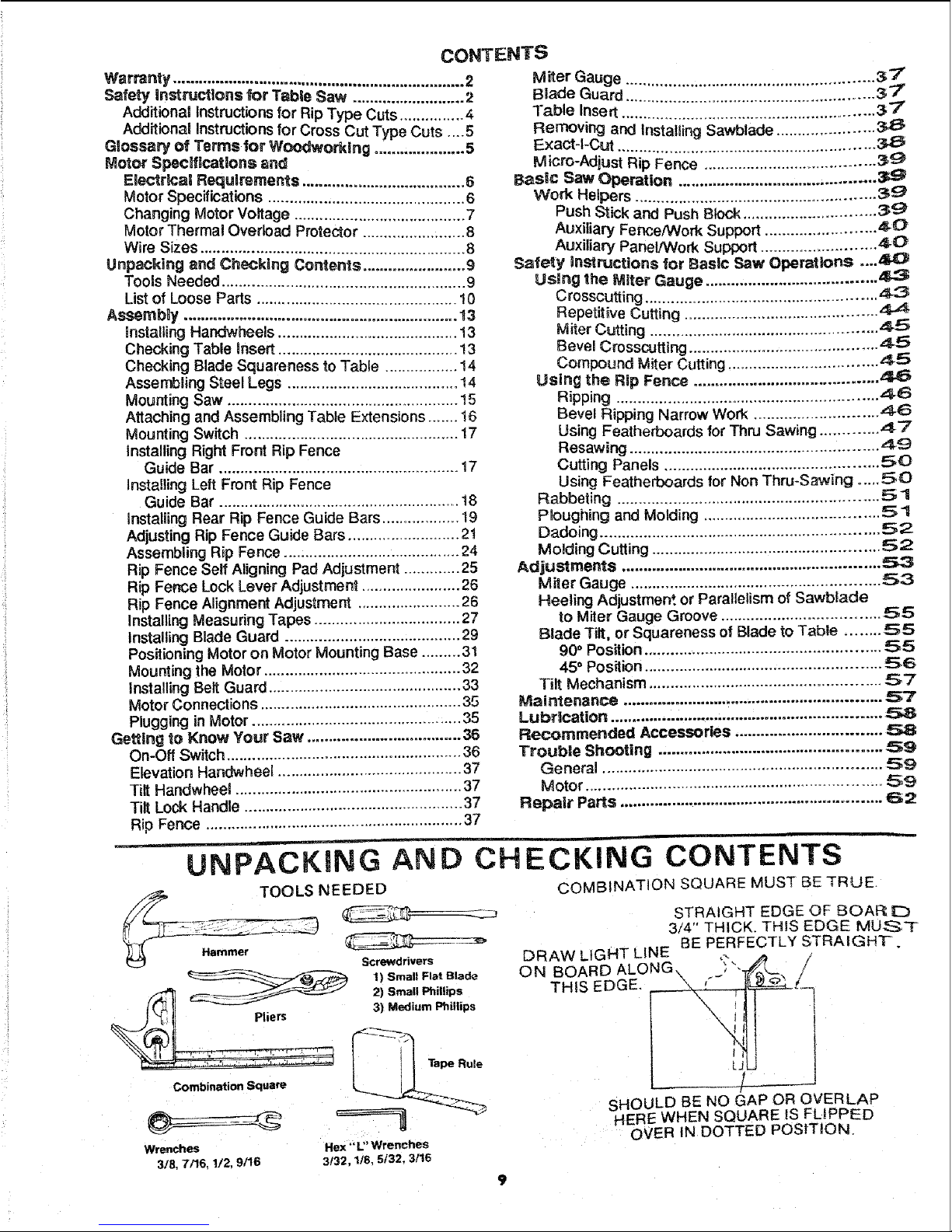
/_p, TOOLS NEEDED
Screwdrivers
'2', °°
i_;]l Pliers 3) Me_lium Phillips
Combination Square
Wrenches Hex ""L"Wrenches
3/8 7/16, 1/2. 9/16 3132, 1/8, 5132, 3/16
UNPACKING AND CHECKING CONTENTS
COMBINATION SQUARE MUST BE TRUE
STRAIGHT EDGE OF BOAF_
3/4" THICK. THIS EDGE MUS*T
BE PERFECTLY STRAIGH'F.
[_RAW LIGHT LINE
ON BOARD
THIS EDGE.
LJ
SHOULD BE NO GAP OR OVERLAP
HERE WHEN SQUARE IS FLIPPED
OVER IN DOTTED POSITION.
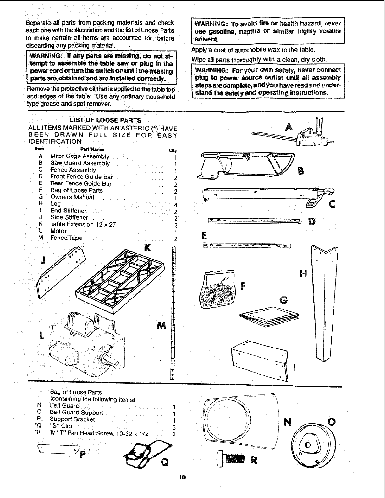
Separate all parts from packing materials and check
each one withthe illustrationand the listof Loose Parts
to make certain all items are accounted for, before
discarding any packing matedaL
j WARNING: If any parts am missing, do not at-
tempt to assemble the table saw or plug in the
power cord or turn the switch on ur_l! the missing
parts are obtained and are Installed correctly.
Remove the protectiveoilthat isapplied tothe table top
and edges of the table. Use any ordinary household
type grease and spot remover.
LIST OF LOOSE PARTS
ALL ITEMS MARKED WITH AN ASTERIC (*) HAVE
BEEN DRAWN FULL SIZE FOR EASY
IDENTIFICATION
item PartName Qtv.
A Miter Gage Assembly 1
B Saw Guard Assembly !
C Fence Assembly
D Front Fence Guide Bar 2
E Rear Fence Guide Bar 2
F Bag of Loose Parts 2
G Owners Manual 1
H Leg 4
I End Stiffener 2
J Side Stiffener 2
K Table Extension 12 x 27 2
L Motor 1
M Fence Tape 2
L
K
: TO _h hazard, never
WARNING8voUChes
use gasoline, naptha or smmllar highly volatile
solvent.
Apply a,coat of automobile wax to the table.
Wipe atl parts thoroughly with a clean, dry cJoth.
WARNING: For your own safety, never connect
plug to power source mJtlst u_i! all assembly
steps are complete, and you have read and under-
stand the safety and operating lnstrucUons.
B
E
• ._ ?=
G H
Bag of Loose Parts
(containing the following items)
N Belt Guard ........... 1
O Belt Guard Support .......... 1
P Support Bracket ......... 1
L,_ip..................... 3
*R Ty"T" Pan Head Screw, 10-32 x 112 3
]0
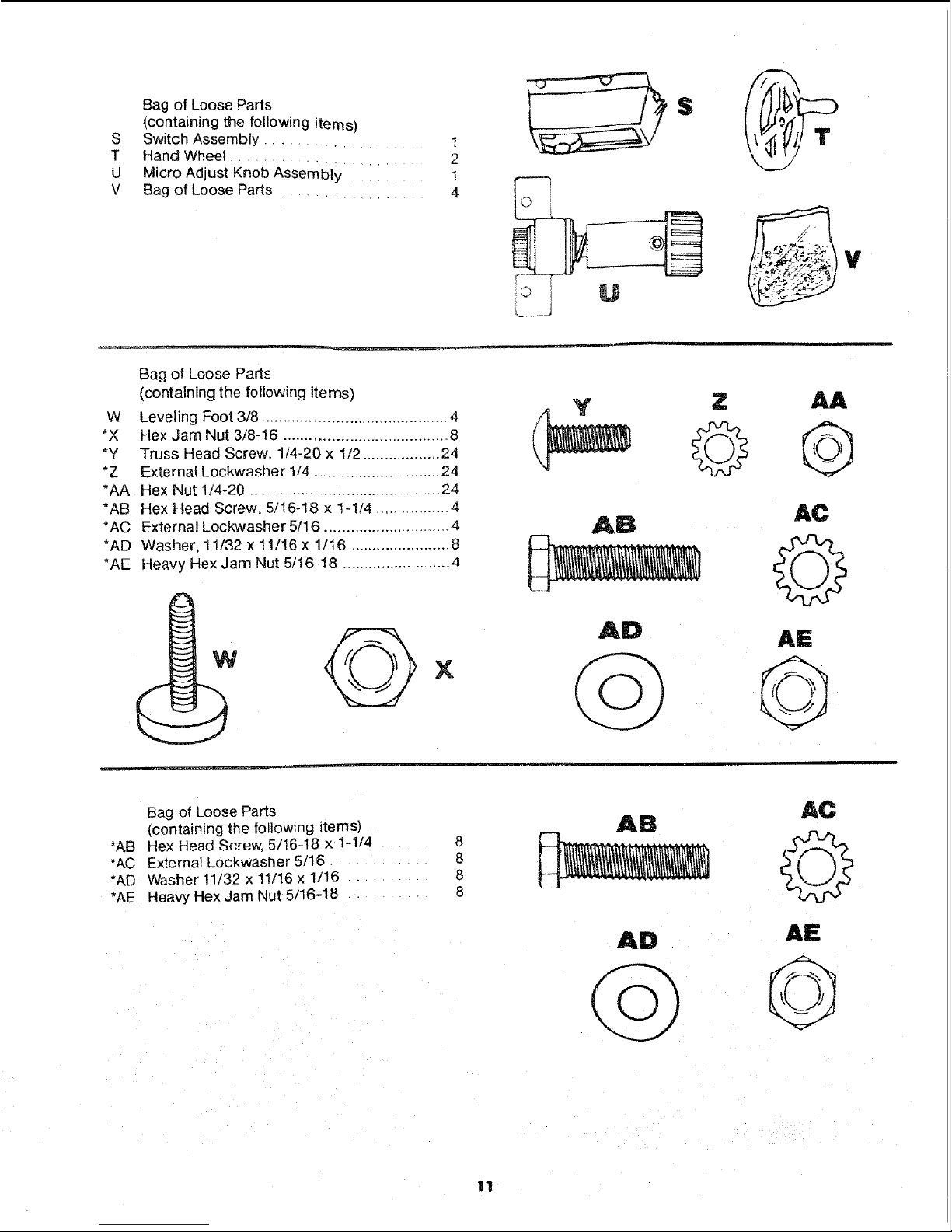
Bag of Loose Parts
(containing the following items)
S Switch Assembly .......... 1
T Hand Wheel .................. 2
U Micro Adjust Knob Assembly ......... 1
V Bag of Loose Parts .............. 4
©
Bag of Loose Parts
(containing the following items)
W Leveling Foot 3/8 ........................................... 4
*X Hex Jam Nut 3/8-16 ...................................... 8
"Y Truss Head Screw, 1/4-20 x 1/2 .................. 24
*Z External Lockwasher 1/4 .............................. 24
*AA Hex Nut 1/4-20 ............................................ 24
*AB Hex Head Screw, 5/16-18 × 1-t/4 ................. 4
*AC External Lockwasher 5/16 ............................. 4
*AD Washer, 11/32 x 11/16 x 1/16 ....................... 8
*AE Heavy Hex Jam Nut 5/16-18 .......................... 4
X
Z JUt
V
Bag of Loose Parts
{containing the following items)
*AB Hex Head Screw, 5/16-18 x 1-1/4 8
*AC External Lockwasher 5/16 . 8
*AD Washer 11/32 x 11/16 x 1/16 ..... 6
*AE Heavy Hex Jam Nut 5/16-18 8
AD
AE
11
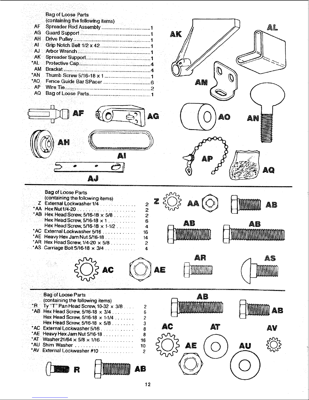
AF
AG Guard Support .................................................. 1
AH Drive Pulley ....................................................... 1
AI Grip Notch Belt 1/2 x 42 .................................... 1
AJ Arbor Wrench. ................................................... 1
AK Spreader Support ............................................. 1
*AL Protective Cap ................................................... 4
AM Bracket .............................................................. 4
*AN Thumb Screw 5/76-18 x 1................................. 1
*AO Fence Guide Bar SPacer .................................. 6
AP Wire Tie ........................... 2
AQ Bag of Loose Parts ............................................ 1
i AF
LJ
AI
AJ
Bag of Loose Parts
(containing the following items)
Z External Lockwasher 1/4 ............. 2
"AA Hex Nut1/4-20 ..................... 2
"AB Hex HeadScrew, 5/16-18 x 5/8 ........ 2
Hex Head Screw, 5/16-18 x 1 .......... 6
Hex Head Screw, 5/16-18 x 1-1/2 ...... 4
*AC External Lockwasher 5/16 ............ 16
*AE Heavy Hex Jam Nut 5/16-18 ........... 14
"AR Hex Head Screw, 1/4-20 x 518 ......... 2
*AS Carriage BoltS/16-!8 x 3/4 .......... 4
O
Bag of Loose Parts
(containing the following items)
*R Ty "T" Pan Head Screw, 10-32 x 3/8 _. 2
*AB Hex Head Screw, 5/16-!8 x 3/4 ....... 6
Hex Head Screw,5/16-18 x 1-1/4 ...... 2
Hex Head Screw, 5/16-18 x 5/8 ........ 3
•AC External Lockwasher 5/16 .......... 8
"AE Heavy Hex Jam Nut 5!16-18 ........... 8
*AT Washer21/_4 × 5/8 x 1t16............ 16
. A
U Shim Washer ..................... 10
*AV External Lockwasher #10 ............ 2
12
AB
AC AT
AV
Au
ASSEMBLY
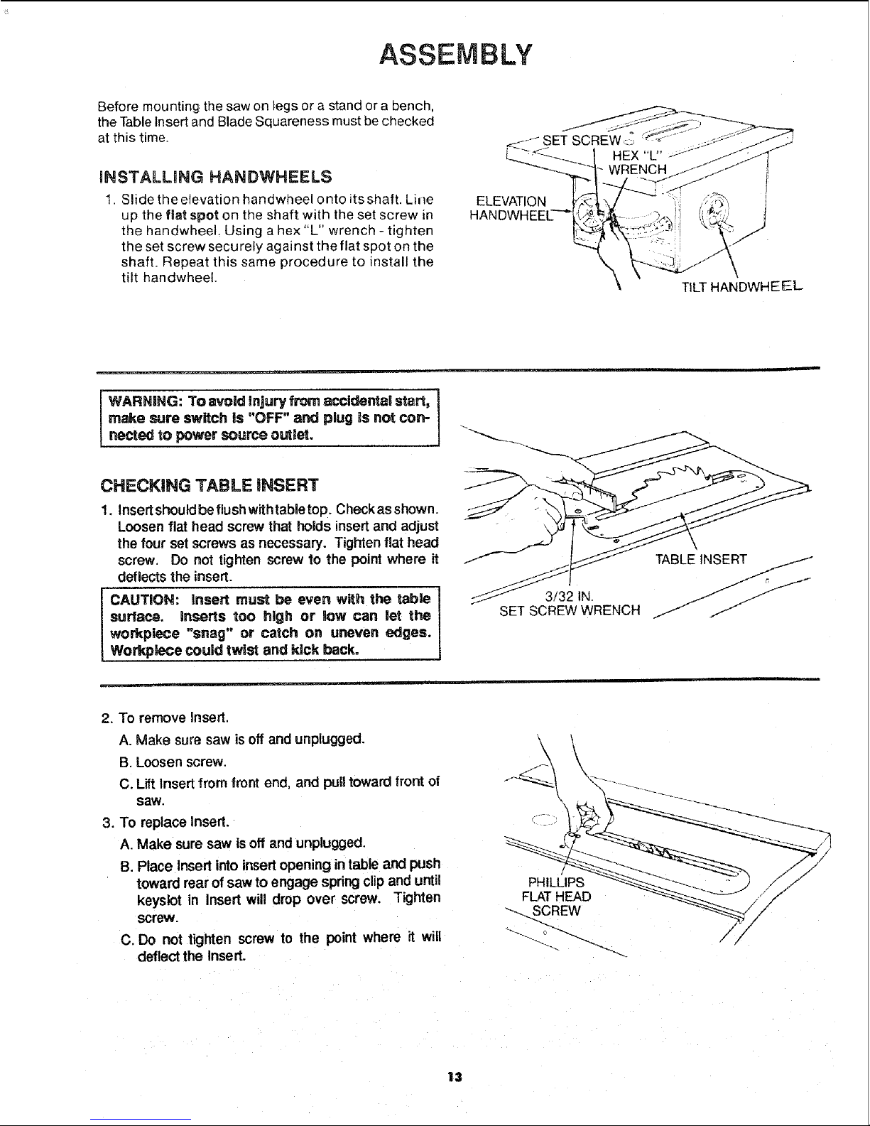
Before mounting the saw on legs or a stand or a bench,
the Table Insert and Blade Squareness must be checked
at this time.
UNSTALLING HANDWHEELS
1. Slide theelevation handwheel onto itsshaft. Line
up the fiat spot on the shaft with the set screw in
the handwheeL Using a hex "L" wrench - tighten
the set screw securely against the flat spot on the
shaft. Repeat this same procedure to install the
tilt handwheel.
ELEVATION
HANDWHEEI
TILT HANDWHEEEL
JWARNING: To avoid injury from accideltlai start,
make sure switch is "OFF" and plug is not con-
nected to power source ouUet.
CHECKING TABLE iNSERT
!. Insert shouldbe flush with table top. Check as shown.
Loosen flat head screw that holds insert and adjust
the four set screws as necessary. Tighten flat head
screw. Do not tighten screw to the point where it
deflects the insert.
CAUTION: Insert must be even with the table I
surface, inserts too high or low can let the I
workplece "snag" or catch on uneven edges. ]
Workplece could twist and kick back°
3/32 IN.
SET SCREW WRENCH
2. To remove insert.
A. Make sure saw is off and unplugged.
B. Loosen screw.
C. Lift Insert from front end, and pufftoward front of
saw.
3. To replace Insert.
A. Make sure saw is off and unplugged.
B. Place Insert into insert opening intable arid push
toward rear of saw to engage spring clipand urltil
keyslot in Insert will drop over screw. Tighten
screw,
C. Do not tighten screw to the point where it wifl
deflect the Insert.
\
PHILLIPS
FLAT HEAD
_-- SCREW
13
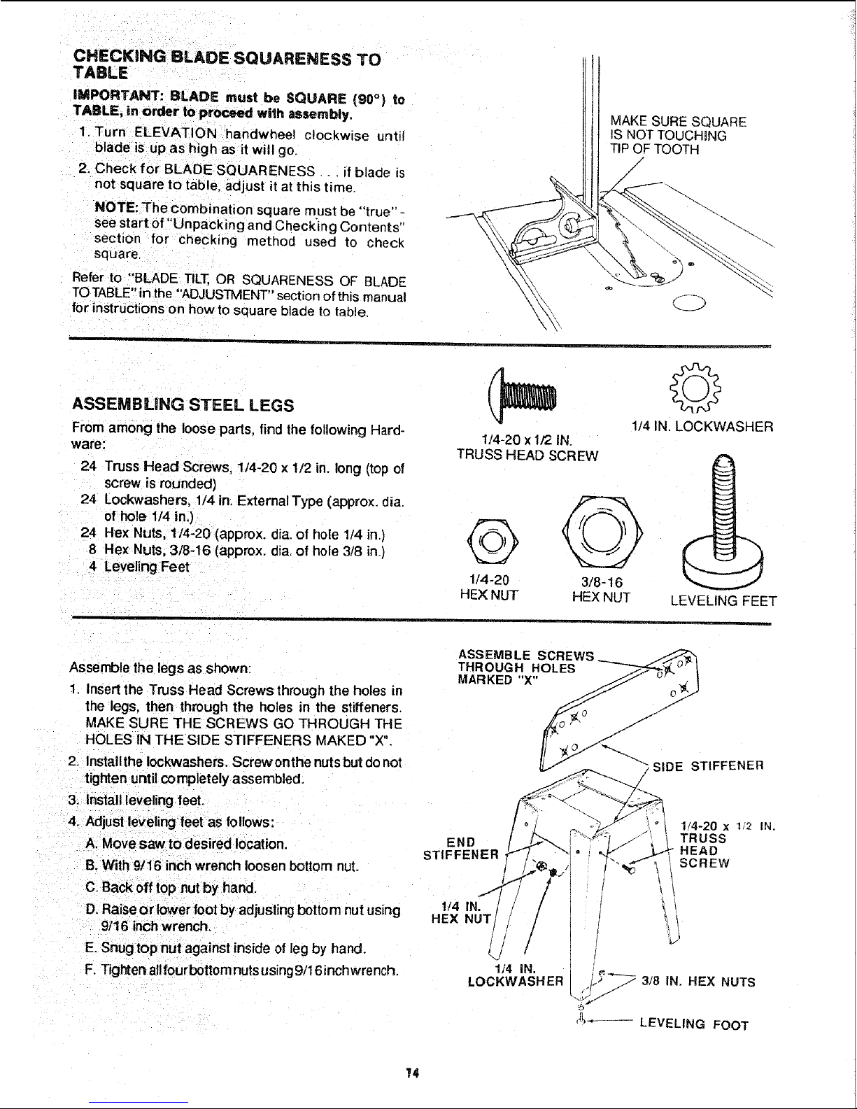
CHECKING BLADE SQUARENESS TO
TABLE
IMPORTANT: BLADE must be SQUARE {90°) to
TABLE, in order to proceed wilh assembly,
1. Turn ELEVATION handwheel clockwise unti!
blade is up as high as it will go.
2. Check for BLADE SQUARENESS _. if blade is
not square to table, adjust it at this time.
NOTE: The combination square must be "true" -
see start of "Unpacking and Checking Contents"
section for checking method used to check
sq LJare
Refer to "BLADE TET, OR SQUARENESS OF BLADE
TO TABLE" in the "'ADJUSTMENT" section of this manual
for instructions on how to sauare blade to table.
MAKE SURE SQUARE
!S NOT TOUCHING
TIP OF TOOTH
/
ASSEMBLING STEEL LEGS
From among the loose parts, find the following Hard-
ware:
24 Truss Head Screws, 1/4-20 x 1/2 in. long (top of
screw is rounded)
24 Lockwashers, 1/4 in. External Type (approx. dia.
of hole 1/4 in.)
24 Hex Nuts, 1/4-20 (approx. dia. of hole 1/4 in.)
8 Hex Nuts, 3/8-16 (approx. dia. of hole 3/8 in.)
4 Leveling Feet
1/4-20 x 1/2 IN.
TRUSS HEAD SCREW
Q
1/4-20
HEX NUT
©
1/4 IN. LOCKWASHER
3/8-16
HEX NUT
LEVELING FEET
Assemble the legs as shown:
1 Insert the Truss Head Screws through the holes in
the legs, then through the holes in the stiffeners.
MAKE SURE THE SCREWS GO THROUGH THE
HOLES IN THE SIDE STIFFENERS MAKED "X".
2. Install the Iockwashers. Screw onthe nuts but do not
tighten until completely assembled.
3. Install leveling feet.
4. Adjust leveling feet as follows:
A. Move saw to desired location.
B. With 9/16 inch wrench loosen bottom nut.
C. Back off top nut by hand.
D. Raise or lower foot by adjusting bottom nut using
9!16 inch wrench.
E. Snug top nut against inside of leg by hand.
F. Tighten all fourbottom nuts using 9/16 inchwrench,
E.o l
STIFFENER F"
1/4-20 x 1/2 IN.
_ TRUSS
HEAD
i SCREW
1/4 IN.
LOCKWASHER, _,,. 3/8 IN. HEX NUTS
_-- LEVELING FOOT
14
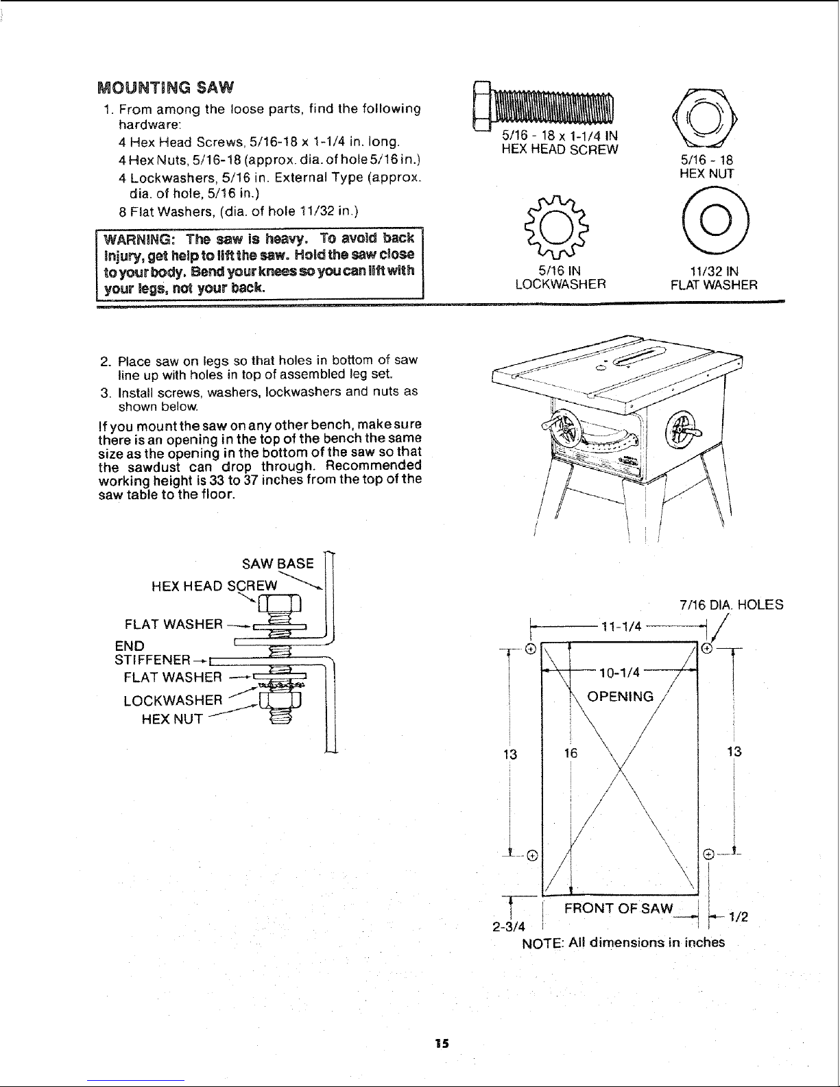
MOUNTING SAW
1. From among the loose parts, find the following
hardware:
4 Hex Head Screws, 5/16-18 x 1-1/4 in. long.
4 Hex Nuts, 5/16-18 (approx. dia. of hole 5/16 in.)
4 Lockwashers, 5/16 in. External Type (approx.
dia. of hole, 5/16 in.)
8 Flat Washers, (dia. of hole !1/32 in.)
WARNING: The saw is heavy. To avoid back
injury, get help to riftthe saw. Hold the saw close
to your body. Bend your knees so you can li_twith
your legs, not your back.
_N
HEX HEAD SCREW
5/16 IN
LOCKWASHER
5/16 - 18
HEX NUT
11/32 IN
FLAT WASHER
2. Place saw on legs so that holes in bottom of saw
line up with holes in top of assembled leg set.
3. Install screws, washers, Iockwashers and nuts as
shown below.
If you mount the saw on any other bench, make sure
there is an opening in the top of the bench the same
size as the opening in the bottom of the saw so that
the sawdust can drop through. Recommended
working height is 33 to 37 inches from the top of the
saw table to the floor.
SAW BASE
FLAT WASHER
END l ...'
STIFFENER--_I _ _
LOCKWASHER /_m==_ l!
HEXNUT
/
13
i
2-3/4
7/16 DIA. HOLES
11-1/4
'_L_PENIN?/
\
16 13
°
/
/
/
/
\/
\
\
\
Q Y
!
--RONT OF SAW __
1/2
NOTE: All dimensions in inches
15
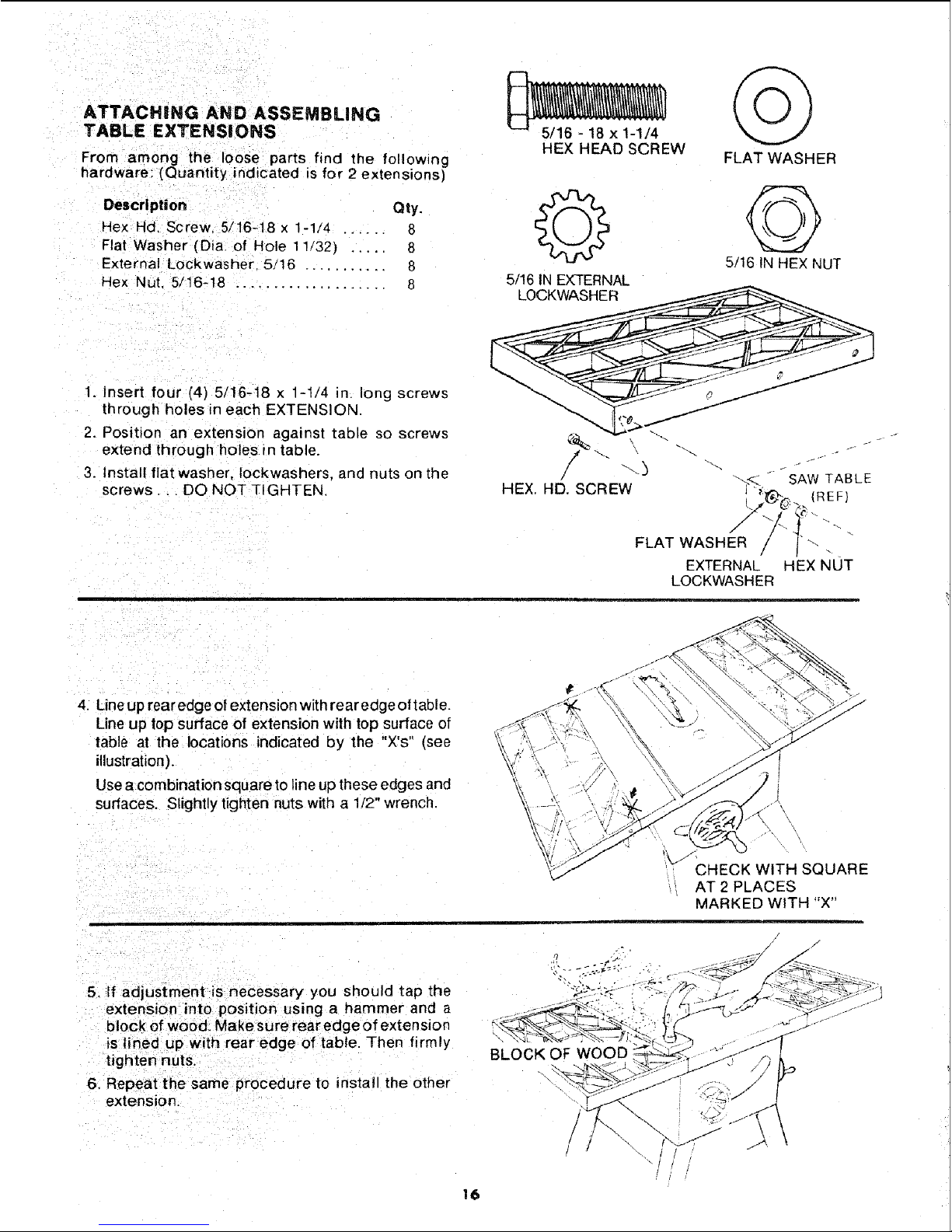
ATTACHING AND ASSEMBLING
TABLE EXTENSIONS
From among the loose parts find the following
hardware: (Quantity indicated is for 2 extensions)
Description Qty.
Hex Hal. Screw 5/16-18 x 1-1/4 ...... 8
Flat Washer (Dia of Hole 11/32) ..... 8
External Lockwasher 5/16 ........... 8
Hex Nut, 5/16-18 .................... 8
1. Insert four (4) 5/16-18 x 1-1/4 in. long screws
through holes in each EXTEN SION.
2. Position an extension against table so screws
extend th rough holes in table.
3. Install flat washer, Iockwashers, and nuts on the
screws, ,. DO NOT TIGHTEN,
HEY, HEAD SCREW
FLAT WASHER
5/16 INHEX NUT
5/16 IN EX-FERNAL
/
/ \--1 "- -
"_<L -- SAW TABLE
HEX HD. SCREW _G > (REF}
FLAT WASHER // / '"
EXTERNAL HEX NUT
LOCKWASHER
4. Une up rearedge of extension with rear edge oftable.
Line up top surface of extension with top surface of
table at the locations indicated by the "X's" (see
illustration).
Use a combination square to line up these edges and
surfaces. Slightly tighten nuts with a 1/2" wrench.
5. If adjustment is necessary you should tap the
extension into position using a hammer and a
block of wood. Make surerear edge of exten sion
is lined up with rear edge of tab{e. Then firmly
tighten nuts
6. Repeat the same procedure to install the other
extension.
BLOCK OF WOOD
CHECK WITH SQUARE
AT 2 PLACES
MARKED WITH "X"
16
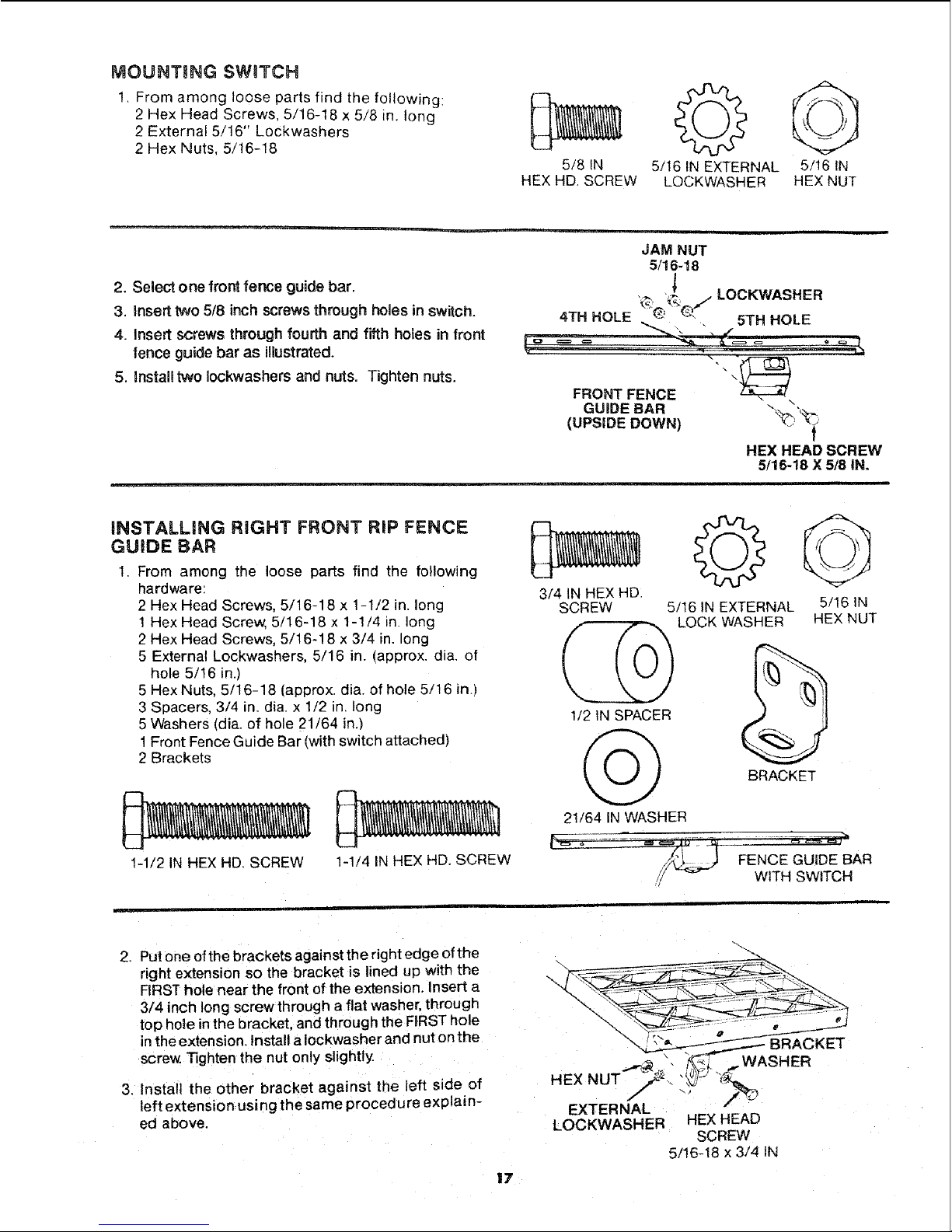
MOUNTING SWITCH
1, From among loose parts find the following:
2 Hex Head Screws, 5/16-18 x 5/8 in. long
2 External 5/!6" Lockwashers
2 Hex Nuts, 5/t6-18
5/8 IN 5/t6 IN EXTERNAL 5/16 IN
HEX HD SCREW LOCKWASHER HEX NUT
2. Select one front fence guide bar.
3. insert two 5/8 inch screws through holes in switch.
4. Insert screws through fourth and fifth holes in front
fence guide bar as illustrated.
5. _nstalltwo Iockwashers and nuts. Tighten nuts.
i
JAM NUT
5/16-18
,]
,_, _Q/LOCKWASHER
4TH HOLE ! " 5TH HOLE
= = "_=. • .===----,_
%
FRONT FENCE \_\
GUIDE BAR "_
(UPSIDE DOWN) _ _
HEX HEAD SCREW
5/1 18 x 5/8iN.
iNSTALLiNG RIGHT FRONT RiP FENCE
GUIDE BAR
1. From among the loose parts find the following
hardware:
2 Hex Head Screws, 5/16-18 x 1-1/2 in. long
1 Hex Head Screw, 5/16-18 x 1-1/4 in. long
2 Hex Head Screws, 5/16-18 x 3/4 in. long
5 External Lockwashers, 5/16 in. (approx. dia. of
hole 5/16 in.)
5 Hex Nuts, 5/16-18 (approx. dia. of hole 5/t6 in.)
3 Spacers, 3/4 in. dia. x 1/2 in. long
5 Washers (dia. of hole 21/64 in.)
1 Front Fence Guide Bar (with switch attached)
2 Brackets
1-1/2 IN HEX HD. SCREW
1-1/4 IN HEX HD. SCREW
3/4 IN HEX HD.
SCREW
1/2 IN SPACER
21/64 iN WASHER
5/16 IN EXTERNAL 5/16 IN
LOCK WASHER HEX NUT
BRACKET
FENCE GUIDE BAR
WITH SWITCH
2. Put one of the brackets against the right edge of the
right extension so the bracket is lined up with the
FIRSThole near the front of the extension. Insert a
3/4 inch long screw through a flat washer, through
top hote in the bracket, and through the FIRST hole
in the extension, install aIockwasher and nut on the
screw. Tighten the nut only slightly.
3. Install the other bracket against the left side of
left extension-using the same procedure explain-
ed above.
17
HEX NUT
EXTERNAL
LOCKWASHER HEX HEAD
SCREW
5/16-18 x 3/4 iN
6TH HOLE SPACER
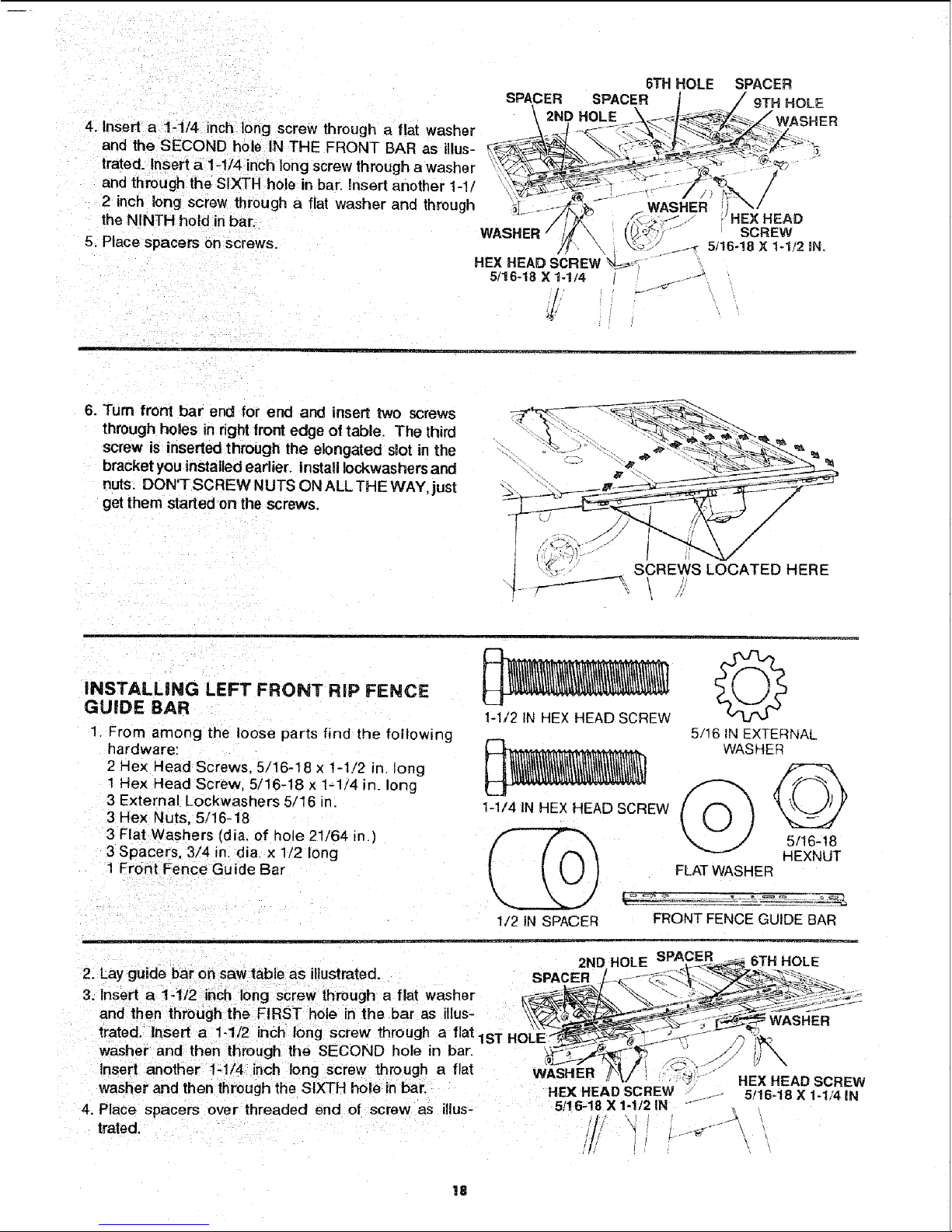
4. Insert a 1-114 inch long screw through a flat washer _-'_-_, -_._t_--_ _,z
and the SECOND hole IN THE FRONT BAR as illus- _-_ _ "%'---,_:_!'_ _"_"_
trated, insert a 1-I/4 nch ong screw throuah a washer "_,_;_ _ - _';v_"" @_
and through the SIXTH hole in bar. nsert another 1-1I " _ _ ", ; ;itS%,. /,
• ',,y3_'_ _'1 _- - ...... / , ,_ _':
2 Inch long screw through a flat washer and through _ ..... & ,SHE i,_ /
-" -J _ ,HEX HEAD
the NINTH hold inbar. / _" .-, [
Place p ce,sonscrews \
HEX HEAD SCREW "N-_.
5/16-18 X 1-114 y"
6. Turn front bar end for end and insert two screws
through hoaes in right tront edge of table. The third
screw is inserted through the elongated slot in the
bracket you installed earlier. Instafl Iockwashers and
nuts. DON'TSCREW NUTS ON ALL THE WAY, just
get them started on the screws.
iNSTALLiNG LEFT FRONT RiP FENCE
GUIDE BAR
1. From among the loose parts find the following
hardware:
2 Hex Head Screws. 5/16-18 x 1-1/2 in. long
1 Hex Head Screw, 5/16-18 x 1-1/4 in_ long
3 External Lockwashers 5/16 in.
3 Hex Nuts. 5/16-18
3 Flat Washers {dia. of hole 21/64 in.)
3 Spacers, 3/4 in. dia. x 1/2 long
1 Front Fence Guide Bar
1-1/2 IN HEX HEAD SCREW
5/16 IN EXTERNAL
WASHER__)
1-1/4 tNHEXHEADSCREW _ _,J ]
5/t6-18
HEXNUT
FLAT WASHER
1/2 IN SPACER
L-_--_ ............................ _-_
FRONT FENCE GUIDE BAR
• 2ND HOLE SPAC_ER ......6TH HOLE
2. Lay gu de bar on saw table as illustrated SPACER / ........._" _'-
3. Insert a !-1'2 inch long screw through a flat washer _L_I_ "_" s;--z::.-:__'_"_1-
and then through the FIRST hole in the bar as illus- .. _
trated Insert a 1-112 _nch long screw through a flat ,_,-u,-,LE_._ --_._=_,._:_--, <-.... _ _:.,,
washer and then through the SECOND hole in bar. _",_:¢'_.,r_'_ ./". ._'X,
. ,_,L.-:_---.."_-_ .._c-_......- _ \
Insert another 1:1t4 ,nch tong screw through a flat WASHER-_i '-_" -- - -
.... ' HEX HEAD SCREW
washer and then through the SIXTH hole in bar. HEX HEAD SCREW J- 5/16-18 X 1-1/4 _N
4. Place spacers over threaded end of screw as illus- 5/16-18 X 1-1/2IN ....
trated. / , _ . .
/
18
5. Turn front bar end for end and insert two of the
bolts through holes on teftside of front edge on saw
table. The third screw is inserted through the bracket
installed earlier
6. Install lockwashers and nuts on bolts. DO NOT
SCREWNUTS ON ALL THEWAY,just get them started
on the screws.
SCREWS LOCATED
HERE
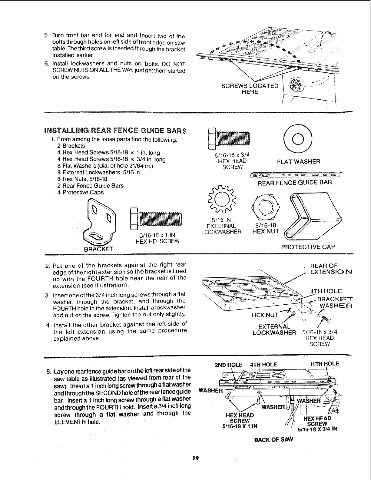
iNSTALLING REAR FENCE GUIDE BARS
1. From among the loose parts find the following:
2 Brackets
4 Hex Head Screws 5/16-18 x 1in. long
4 Hex Head Screws 5/16-18 x 3/4 in. long
8 Flat Washers (dia. of hole 21/64 in.)
8 External Lockwashers, 5/16 in.
8 Hex Nuts, 5/16-18
2 Rear Fence Guide Bars
4 Protective Caps
5/16-18 x 3/4
HEX HEAD
SCREW
5/t 6 IN
FLAT WASHER
REAR FENCE GUIDE BAR
EXTERNAL 5/16-18
LOCKWASHER HEX NUT
BRACKET
5/16-18 x 1 IN
HEX HD. SCREW
EXTERNAL
LOCKWASHER
2. Put one of the brackets against the right rear
edge of the right extension so the bracket is lined
up with the FOURTH hole near the rear of the
extension (see illustration).
3. Insert one of the 3/4 inch long screws through a flat
washer, through the bracket, and through the
FOURTH hole inthe extension. Install a Iockwasher
and nut on the screw. Tighten the nut only slightly
4. Install the other bracket against the left side of
the left extension using the same procedure
explained above.
PROTECTIVE CAP
REAR OF
5/16-18x3/4
HEX HEAD
SCREW
5. Layone rearfenceguidebarontheleft rearsideofthe
saw table as illustrated(as viewed from rear of the
saw). Insert a I inch long screw through a flat washer
and throughthe SECOND hole of the rearfence guide
bar. Insert a 1inch long screw through a flat washer
andthroughthe FOURTH hold. Insert a3t4 inch long
screw through a flat washer and through the
ELEVENTH hole.
2ND HOLE 4TH HOLE
WASHER
HEX HEAD
SCREW
5/15-18 X 1 IN
WASHER
BACK OF SAW
tlTH HOLE
l
HEX HEAD
SCREW
5,'16-18X 3/4 IN
19
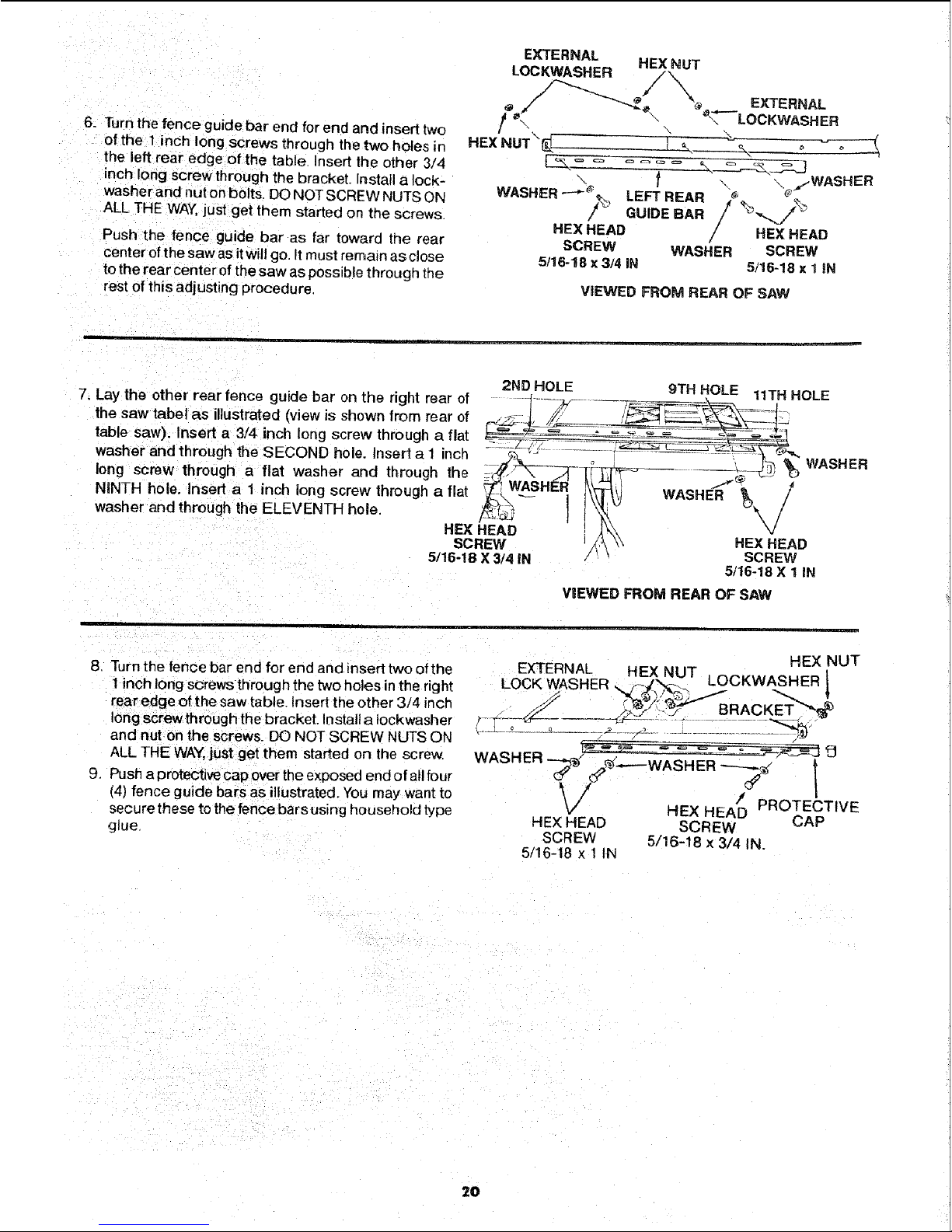
6. Turnthefenceguidebarendforendandinserttwo
ofthe1inchlongscrewsthroughthetwoholesin
theleftrearedgeofthetable.Inserttheother3/4
inchlongscrewthroughthebracket.Installalock-
washerandnutonbolts.DONOTSCREWNUTSON
ALLTHEWAY,justgetthemstartedonthescrews.
Pushthefenceguidebarasfartowardtherear
centerofthesawasitwillgo.Itmustremainasclose
totherearcenterofthesawaspossiblethrougt_the
restofthisadjustingprocedure,
EXTERNAL
LOCKWASHER H_x_T
HEXNUT\_. _ \__ , - o
_- _ "_ \ .,/WASHER
WASHER .-"-'__' LEFT REAR _' _"
,f_ GUIDE BAR / %_..._%'
REXHEAD / HE×HEAD
SCREW WASHER SCREW
5/16-18 x 3/4 iN 5/16-18 x 1 iN
VIEWED FROM REAR OF SAW
7. Lay the other rear fence guide bar onthe right rear of 2ND HOLE 9TH HOLE 11TH HOLE
the saw tabel as illustrated (view is shown from rear of _-iI_-_ ....... _T_ :I_
tabe saw " =_ _-F_ - =- _ ::--= _ -_---_
). Insert a 3/4 inch long screw through a flat
washer and through the SECOND hole. Insert a I inch ..... _;,_,JZ - ---_-_ i-_-,:. -_ _ ..::=_'_F-c,_,,
long screw through a flat washer and through the :,_?_'-_----_-3i:_-_ _ ____.Z_ _) WASHER
NINTH hoe nsert a 1 inch long screw thiough a fiat _ WASHL_ _'F'_,) t.,Aeu=_ /
washer and through the ELEVENTH hole _-_
• I \ /
HE×HEAD
SCREW _k \ ^ H_u
5/16-18 X 3/4 IN / _ SCREW
5/16-18 X 1 IN
VIEWED FROM REAR OF SAW
8 Turn the fence bar end for end and insert two ofthe
1 inch long screws through the two holes in the right
rear edge of the saw table. Insert the other 3/4 inch
long screwthrough the bracket. Install a iockwasher
and nut on the screws. DO NOT SCREW NUTS ON
ALL THE WAY,just get them started on the screw.
9. Push a protective cap overthe exposed end of allfour
(4) fence guide bars as illustrated. You may'want to
secure these to thefence bars using household type
glue,
HEX NUT
EXTERNAL
. HEjX_NUT LOCKWASHER_
LOCK WASHER
WASHER _" _: .._-: ;:-;. ,--_-_J 9
T
t o- /
/ PROTECTIVE
_'/ HEX HEAD
HEX HEAD SCREW CAP
SCREW 5/16-18 x 3/4 IN.
5/16-18 x 1 IN
2O
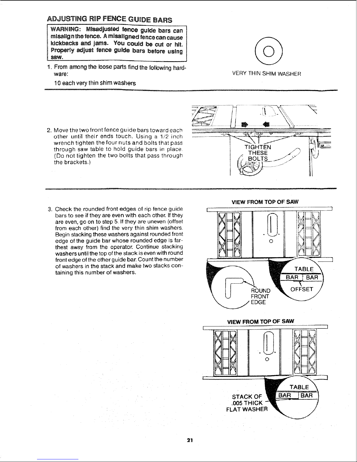
ADJUSTING RIP FENCE GUIDE BARS
WARNING: Mlsadjusted ience guSde bars can
mBsalig n the fence. A misaglgned fence can cause
kickbacks and jams. You could be cut or hit.
Proper_y adjust fence guide bars before using
1. From among the loose parts find the following hard-
ware:
10 each very thin shim washers
VERY THIN SHIM WASHER
2. Move the two front fence guide bars toward each
other until their ends touch. Using a 1/2 inch
wrench tighten the four nuts and bolts that pass
through saw table to hotd guide bars in place.
(Do not tighten the two bolts that pass through
the brackets.)
THESE _i!]
BOLTS !! "_'
3. Check the rounded front edges of rip fence guide
bars to see if they are even with each other, tf they
are even, go on to step 5. If they are uneven (offset
from each other) find the very thin shim washers.
Begin stacking these washers against rounded front
edge of the guide bar whose rounded edge is far-
thest away from the operator. Continue stacking
washers until the top of the stack is even with round
front edge of the other guide bar. Count the number
of washers in the stack and make two stacks con-
taining this number of washers.
VIEW FROM TOP OF SAW
VIEW FROM TOP OF SAW
_-_=_
/
o
J _
\_
X=
I " '
STACK OF
.005 THICK
FLAT WASHER
!
/
21
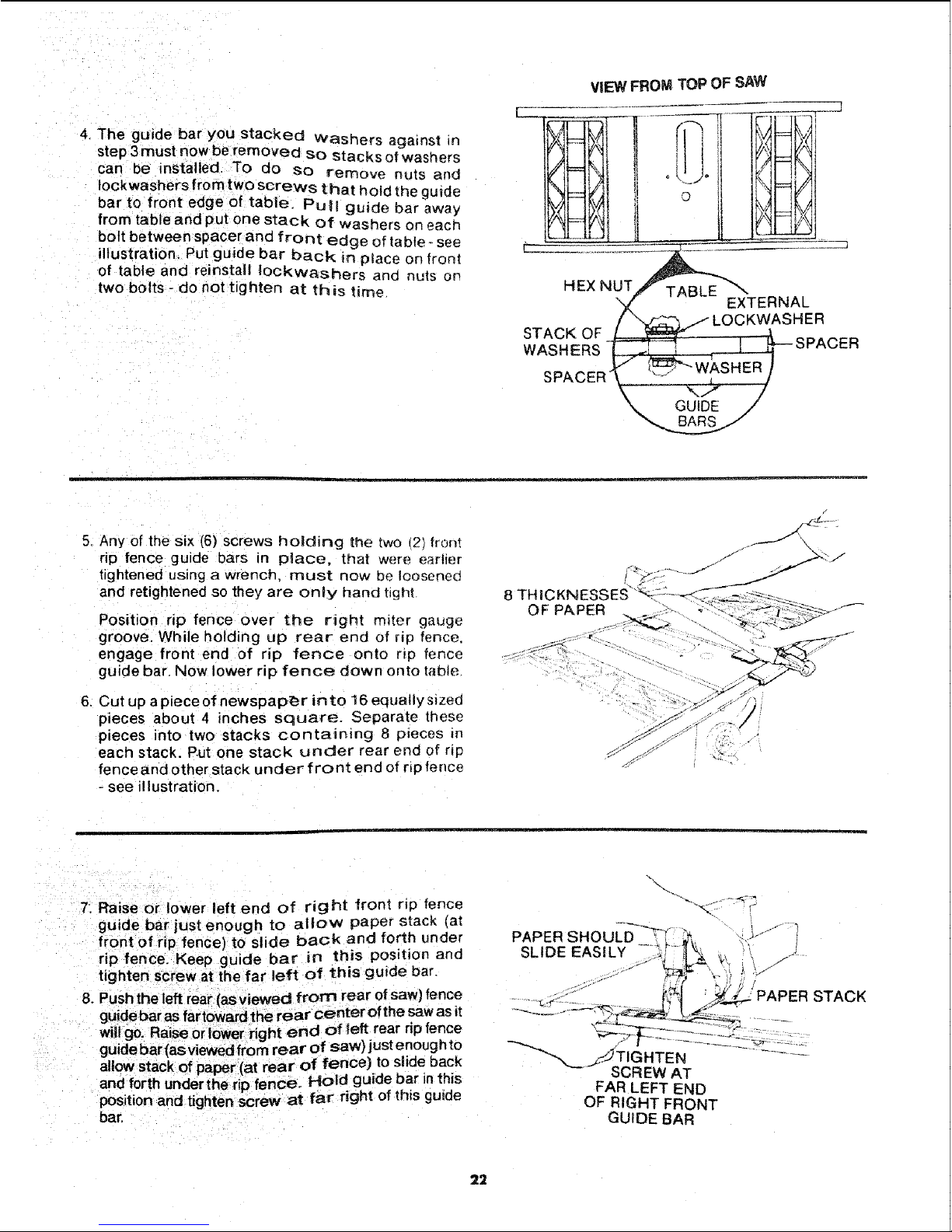
4. The guide bar you stacked washers against n
step 3 must now be removed so stacks of washers
can be installed. To do so remove nuts and
Iockwashers from tWO screws that hold the guide
bar to front edge of table. Pull guide bar away
from table and put one stack of washers on each
bolt between spacerand front edge of table - see
illustration. Put guide bar back in place on front
of table and reinstall [ockwashers and nuts on
two bolts - do not tighten at th is time
VIEW FROM TOP OF SAW
©
HEX NUT
STACK OF
WASHERS -
SPACER
TABLE
EXTERNAL
;HER
5. Any of the six (6) screws holding the two t21 front
rip fence guide bars in place, that were earlier
tightened us=ng a wrench_ must now be loosened
and retightened so they are only hand tight
Position rip fence over the right miter gauge
groove. While holding up rear end of Np fence.
engage front end of rip fence onto r=p fence
guide bar. Now lower rip fence down onto table
6. Cut up a piece of newspaper in to 16 equally s=zed
pieces about 4 inches square. Separate these
pieces into two stacks containing 8 p_eces m
each stack. P.utone stack under rear end of rIp
fence and other stack under front end of rip fence
- see illustration.
OF PAPER
t
7: Raise or lower left end of right front rip fence
guide bar just enough to aliov_ paper stack (at
front of rip fence) to slide back and forth under
rip fence. Keep guide bar in this position and
tighten screw at the far left of this guide bar.
8. Pushthe left rear (as viewed from rear of saw) fence
willgo. Raise or lower right end of left rear rip fence
allow stack of paper(at rear of fence) to slide back
and forth under the rip fence. Hold guide bar inthis
position and tighten screw at far right of this guide
bar.
PAPER SHOI
SLIDE EASILY
SCREW AT
FAR LEFT END
OF RIGHT FRONT
GUIDE BAR
PAPER STACK
22
 Loading...