

Craftsman 113.29501 Assembly, Operating Instructions And Parts List
--A
i4---.
i
ii------,
I?.-j.
:....;-
?
t'
..
<*
.,:!
*>.
.ka
/
,j
$;:
i-:.....
;.
...
*:,;-
>:
,$
ASSEMBLY,
OPERATING
INSTRUCTIONS
,
,,:.
..
,i
...
.
.
.,,:.,
...
2.
;-
.:
/
AND
PARTS
LIST
FOR
L-.
--
,.-..
-...
__
.
CRAFTSMAN
.I2
INCH
RADIAL
SAW
I
MODEL
NUMBER
1
13.29501
p
I
I
The Model Number will be found on a plate attached to your saw,
at the left side of the base.
Always mention the Model Number in
all correspondence regarding the CRAFTSMAN RADIAL SAW or when
ordering repair parts.
Carefully read the instructions provided, observe the simple
safety precautions
and
you
will have many hours
of
satisfactory
use
from
your
new Craftsman
tool.
1
HOW
TO
ORDER REPAIR PARTS---,
All
parts listed herein may be ordered through SEARS, ROEBUCK AND
I
CO.
or SIMPSONS-SEARS LIMITED. When ordering parts
by
mail from
the
catalog order house which serves the territory in which you live,
selling prices will be furnished on request or parts
will be shipped at
prevailing prices and you will be billed accordingly.
I
/
WHEN
ORDERING
REPAIR PARTS, ALWAYS
GlVE
THE FOLLOWlNG
I
INFORMATION AS SHOWN
IN
TH!S LIST:
1.
The PART NUMBER
3.
The
MODEL
NUMBER
1
13.29501
2.
The PART NAME
4.
The
NAME
of item - RADIAL SAW
COAST
TO
COAST NATION-WIDE
SERVICE
FROM
SEARS
FOR
YOUR
CRAFTSMAN RADIAL SAW
SEARS, ROEBUCK
AND
CO.
and
SIMPSONS-SEARS LIMITED in Canada
back up your investment with quick,
expert mechanical service and genu
-
ine CRAFTSMAN replacement parts.
If
and when you need repairs or serv
-
ice, call on us to protect your invest
-
ment
in
this fine piece
of
equipment.
I
J
SEARS,
ROEBUCK
AND
C0.-
U.
S.
A.
IN
CANADA,
SIMPSONS-SEARS
LIMITED
1
Ptinted
in
U.
S.A.
Part
No.
63161
PObVER
TOOL
SAFETY
...
APdD
YOU
3
MINUTES
of required reading for the home Crafts-
safety
in
mind, permitting you to use the tool without
man..
.
whether this
is
your first purchase or you're
concern
so long
as
certain basic rules are observed.
an old hand
at
power tools.
We'd
like
to call particular attention to some of the
YOU'VE
JUST BOUGHT A QUALITY
SEARS
TOOL.
more important rules to follow for maximum enjoy-
designed
to
give
you many years of top performance
rnent of your Sears power tools.
and trouble
-
free operation.
It's
also
designed with'
1.
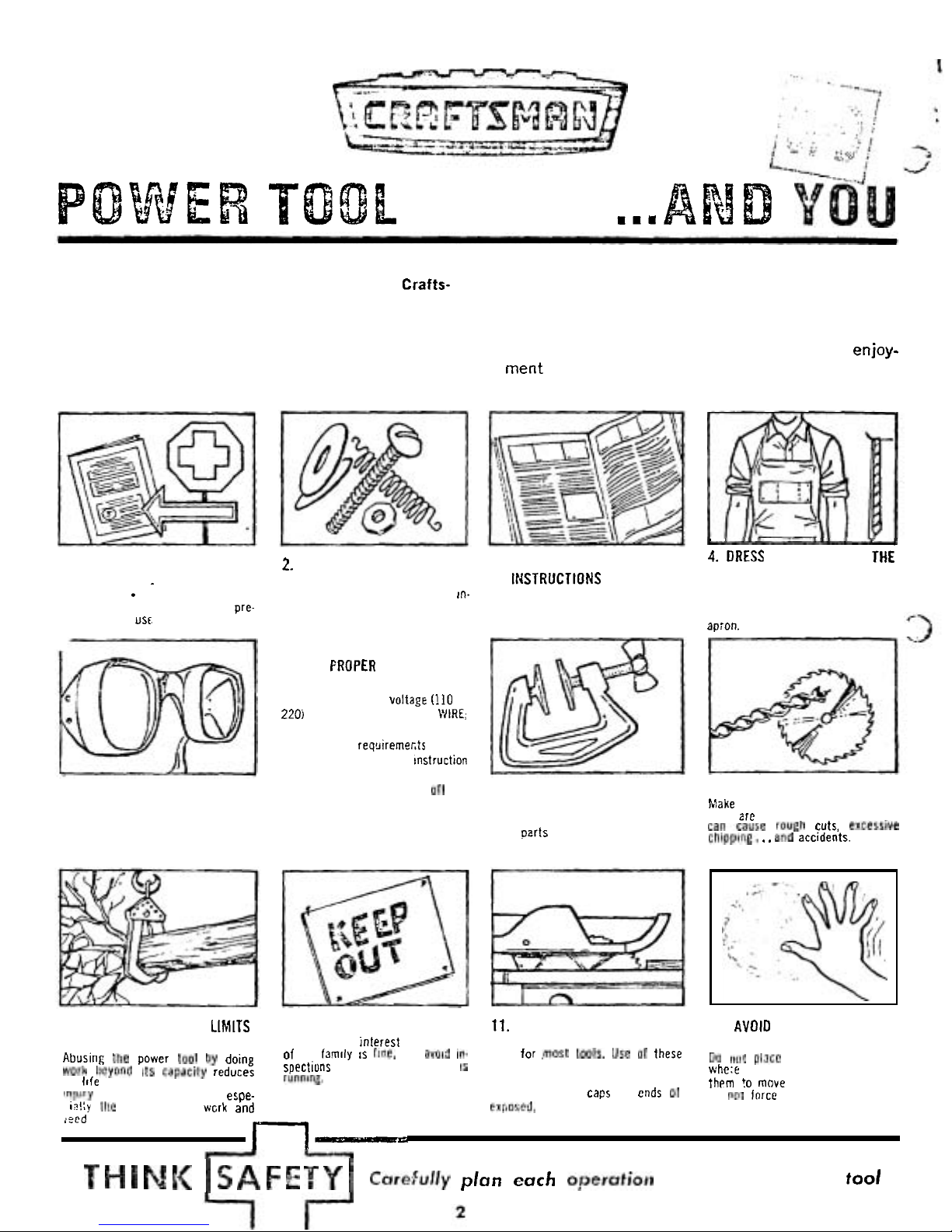
READ THE INSTRUCTION
MANUAL.
.
.
completely accurately.
Pay
special attention to safety pre-
cations and usc of safety features.
5.
WEAR
SAFETY GLASSES
Safety glasses or eye shields are
recommended for all power tool
operations.
2.
INSPECT THE POWER TOOL
THOROUGHLY
Set
up
Ihe machine according to rn-
structions. Make certain all parts
are included.
6.
USE PROPER ELECTRICAL
CONNECTIONS
Make
certain proper voltag~
(110
or
220)
is used. USE
A
GROUND
\'/IRE;
AND
A
SUITABLE
PLUG. IF REQUIRED.
Check fusing
reqclireme~ts of the
tool as outlined in the
instruction
manual.
Get in the habit
of
turning of! the
tool when not in use.
3.
FOLLOW OPERATING
It4STRUCTIONS CAREFULLY
They have been developed to in
-
sure correct procedure and pre
-
vent accidents.
4.
DRESS
P
R
O
P
E
R
L
Y
FOR
THE
WORKSHOP
Gel rid of loose clothing, roll up
sleeves (or fasten securely). remove
your tie, wear a snug
-
fitting shop
apion.
7.
DOUBLE-CHECK HOLDING
8.
KEEP CUTTING TOOLS SHARP
FIXTURES
Make certain blades, drills. cutters,
Lock all clamps tightly.
etc..
zre in top shape. Dull tools
Spin
pzrts by hand
to
check against
cancause rough cuts, excessive
misalignment or looseness before
chip~lng.
. .
and accidents.
turning on tool.
9.
DON'T EXCEED THE LIMITS
10.
KEEP SPECTATORS AWAY
11.
SAFETY
GUARDS
12.
AVOID AWKWARD HAND
OF
THE POWER TOOL
Curiosity and Interest on the part Accessory safety guards are avail
-
POSITIONS
Abusing the power tool
by
doing
of
the
family
IS
ffne, but
avad
in-
able for .most tools. Use
of
these
IICI~
pl~ce hands in a position
work lleyond its capacity reduces
spections when the poner tool
IS
guards is highly recommended.
whe:e a sudden slip could cause
its
Itfe and increases the chance
of
runfllne.
th~rn !o move into a cutting tool.
ln~c~fy to the operator. Watch espe-
Keep protective caps on ends of
Do
POI
inrcc
work abnormally into
in!:y
the sizes of the wcrk and er[~osrd, rotating shafts. any cutting tool.
.
15cd rate.
n-
T
H
N
I.(
I
S
A
F
E T Y
I
cart?fdr~
plan
each
operofiotl
before
turning
on
tool
.
.
..
,
. .
...
.
.
.
I
.
.i
:,
..
:;
;;.
;..
J,'
:
'
ASSEMBLING
AND
ADJUSTING
YOUR
SAW
/:::...i;:d::..::j
;
y;,..;
-
:'
'.
,
.+?';
i
,.
.>
1
.
POWER
SMPPLY
&
MOTOR
CONNECTIONS
lead. (The black motor cord lead is al!Zidy-con
nected to the overload protector.)
-
MOTOR
SPECIFiCATt ONS
b.
Connect the
GREEN
and
BROWN
leads to the BLUE
The AC motor used
in
this saw
is
a capacitor start, non-
lead.
reversible type, with the following specifications:
c. Twist bare ends of wires together and install a wire
Horsepower
.........
3
nut on each connection.
Voltage
.............
120 / 240
Amperes
............
13
/
6.5
d.
Push all leads carefully into motor terminal box and
Cycles
..............
60
install terminal box cover.
~l;ase
..............
Single
RPM
................
3450
Rotation (viewed from
.....
saw blade end) Clockwise
CAUTION: The motor
is
wired for 115-120
volt operation. Connect to a 20 amp. branch
circuit and use
a 20 amp., time-delay fuse.
ELECTRICAL
CONNECTiONS
NOTE: This.saw motor
is
wired at the factory
for 120
-
volt,
60
cycle,
AC
service as shown
in figure 1 and described in paragraph
1,
below. Under normal home workshop use
with proper voltage to the motor, the saw
will
operote with adequate efficiency. How
-
ever, if any of the following conditions exist,
it may be necessary to reconnect the sow
for 240 volts AC as described in paragraph
2, below.
1.
Continuous heavy-duty use.
2. Undersize wiring in circuit from motor to
power source, or overloaded circuit.
3.
Low voltage from power source to motor
(which
may be due to overlooded power
source).
The power cord must also be changed from the 120
-
volt type
to the 240
-
volt type, when changing to 240-volt operation.
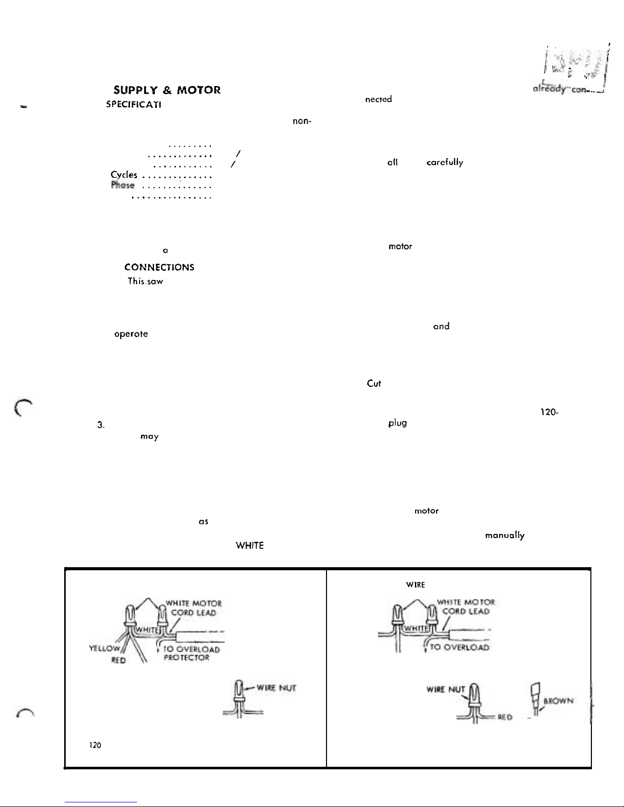
1.
Connections For 120-Volts
AC.
(See figure 1.) When
replacing a motor or connecting the saw to 120
-
volts
for any reason, make sure the wires inside the motor
terminal box are connected
as follows:
a.
Connect the
YELLOW,
WHITE, BLACK and RED leads
from the motor terminal box to the
WHlTE motor cord
2.
Connections For 240-Volts
AC.
(See figure
2.)
When
connecting the motor for 240
-
volt operation, the fol
-
lowing connections must be made inside the motor ter
-
minal
box:
a. Connect the
YELLOW,
WHITE and BLACK leads
from
mator terminal box to the WHITE motor cord
lead. Twist bare ends together and install a wire
nut as shown in figure 2.
b.
Leave the BROWN lead (from overload protector)
disconnected and insulate
it
with tape to prevent
short circuiting inside motor terminal box.
c. Connect the GREEN, RED and BLUE leads together,
twist bare ends
and install a wire nut.
d.
Push all leads carefully into motor terminal box and
install terminal box cover.
3.
Modifying
the
Power Cord.
a.
Cut off the existing molded plug (for 120-volts).
b.
Attach an appropriate 240-volt plug.
CAUTION: Do notconnect the stcndard
120-
volt plug to a 240-volt receptacle.
MOTOR
SAFETY PROTECTION
The saw motor
is
equipped with a manual-reset thermal
overload protector, designed to open the power line circuit
when the motor temperature exceeds a safe value.
1. If the protector opens the line and stops the saw motor,
press the saw switch to the
"
OFF'
position immediately
and allow the
motor to cool.
2.
After cooling to a safe operating temperature, the over
-
load protector can be closed manually
by
pushing in
the red button on the motar capacitor cover.
If
the red
I
WIRE
NUTS
BLACK
GREEN BROWN
BLUE
110
VOLTS
figure
1
I
WIRE
NUTS
YELLOW
BLACK
PROTECTOR
GREEN
TAPE
BLUE
UNCONNECTED
EXPOSED
WlRE
240
VOLTS
Figure
2
button will not snap into place immediately, the motor
is
still
too hot and must be allowed to cool for a while
longer. (An audible click will indicate protector
is
closed.)
3.
As
soori os the red button will snap into running position,
the
saw moy be started and operated normally by press
-
ing the saw switch to the
"ON"
position.
4.
Frequent opening of fuses or circuit breakers may result
if
motor
is
overloaded, or if the motor circuit
is
fused
with a fuse other than those recommended.
Do
not use
a fuse of greater copocity without consulting the power
company.
5.
Although the motor
is
designed for operation on the
voltage and frequency
specified on motor nameplate,
normal loads will be handled safely on voltages not
more than 10% above or below the
narneplote voltage.
Heavy loads, however, require that voltage at motor
terminals be not less than the voltage specified on
nameplate.
6.
Most motor troubles may be traced to loose or incorrect
connections, overloading, reduced input voltage (which
results when small size wires are used in the supply
circui:) or when the supply circuit
is
extremely long.
Always check connections, load and supply circuit when
the motor fails to perform
satisfactorily. Check wire
sizes and lengths with the table in the next poragraph.
WIRE SIZES
The followin
g
table lists recommended wire sizes for con
necting the motor to the power source. These sizes should
be maintained for trouble
-
free operotion of the saw.
Length
of
Wire
Sire
Required
Condurtor
(American Wire Gauge
No.)
120 Volt Lines
240 Volt Lines
50 feet or less No.
12
No. 14
100 feet or less No.
10
No.
12
100 feet to
150
feet No.
8
No. 10
150 feet to 200 feet No.
6
No.
8
200 feet to 400 feet No.
4
No.
6
NOTE: For circuits of greater length, the wire
size must be increased proportionately in or
-
der to deliver ample voltage to the saw motor.
:-..
NOTE: The seven basic "steps" that follow
-'---..
are essential in order to insure correct align-
/
ic:
;:.-;
.,
I.
:.
..
.
ment of the saw.
:.'
.
.
I
C.
2. ..
,
7
>.\,
..~.
..
_
.
..
..
;
&,
'.
3'L.
:'
4
WARNING: Make sure the power cord is
,p
..
t;.
not plugged into an electrical outlet when
2
b?,
working on the saw.
-..__.
---
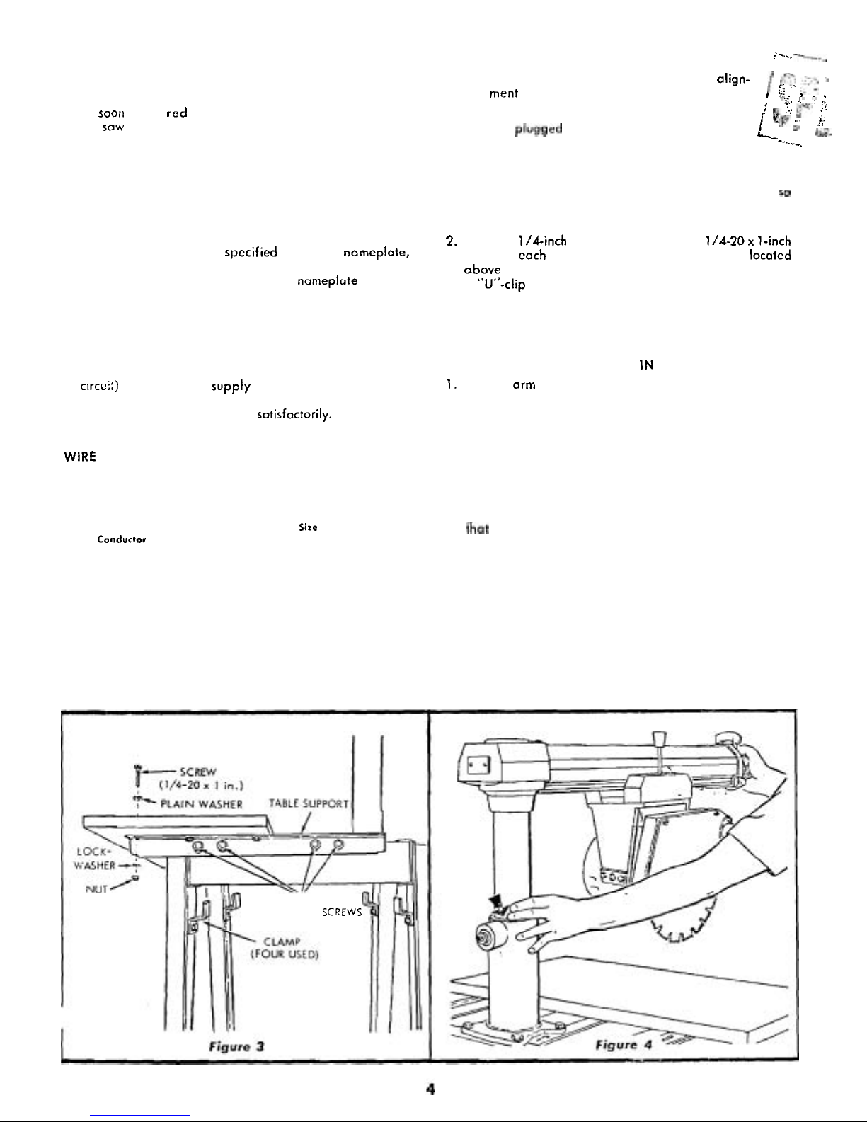
STEP
ONE - INSTALLATION OF FRONT TABLE
1. Place the large front table board on toble supports
so
that holes in board match holes in supports. (See fig
-
ure
3.)
2. Place a l/dinch plain wosher and a l/4-2Ox l-inch
screw
in
eoch of the seven counterbored holes located
above the table supports. One screw
is
threaded into
a
"U"-clip nut mounted on the No. 2 support.
3.
Attach lockwashers and nuts to the six screws in the
table supports. Do not tighten these screws at this time.
STEP
TWO
-
CHECKING
FOR
LOOSENESS
OF
COLUMN
TUBE
IN
COLUMN SUPPORT
1.
Tighten arm latch handle
(22,
figure 20.)
2.
Grasp arm latch handle (22, figure 20) with one hand
and hold fingers of other hand at parting line between
column tube and column support. (See figure 4.)
Apply
gentle side force to the radial arm in opposing directions.
Any looseness between column and column support (in
-
dicated by arrow in figure
4)
can be felt with fingers.
3.
If looseness can be felt, at point indicated by the arrow
in figure 4, perform operations outlined in instructions
hat follow:
NOTE Before attempting to adjust the col
-
umn tube key, the function of this adjustment
should be understood. Figure 5 shows a sec
-
tional view through the column tube support
(looking downward) at this location. By loos
ening the left-hand set screw and tightening
the right
-
hand set screw the column tube key
will be forced tighter into the column tube
keyway. Conversely, loosening the right
-
hand set screw and tightening the left-hand
TABLE
SUPPORT
MOUNTING SCREtAJS
set screw, the column key will be retracted
out of the column tube keyway. The set
screw in outer end of column
tube key must
be loosened while adjustment
is
being made
and tightened with
medium firm~icss after
adjustment
is
completed. This screw applies
pressure on the Nylon friction plug and pro
-
vides smoother elevation movement of col
-
umn tube. This set screw should be tightened
to provide maximum smoothness of opera
-
tion. Right
and
left positions are given
with operator facing the saw
-
stand
-
ing
in
front of saw table.
a.
Loosen set screw in center of column tube key. (See
figure
5.)
b.
Loosen left-hand set screw
1/4
turn. (See figure
5.)
c. Tighten right-hand set screw. (See figure
5.)
d.
Tighten left-hand set screw. (See figure
5.)
e. Turn.elevution crank to raise and lower radial arm.
(See figure
6.)
If too tight, loosen right-hond set screw
(figure
5)
slightly ond check again for smooth oper
-
ation. When correct, tighten left-hand set screw
f.
Tighten set screw in center of column tube key (figure
5)
until smoothest operation
is
obtained.
g.
Lock the yoke clamp handle
(7,
figure
20)
and
bevel lock knob
(17)
securely.
STEP
THREE-
SQUARING
THE CROSS CUT
1.
Loosen the arm latch handle
(22,
figure
20)
1/4
turn.
Make sure the yoke clamp handle
(7)
and bevel lock
knob
(1
7)
are tight.
rl
2.
Pull the arm latch lever
(1)
outward and move radial
arm approximately
lo0
to the right. Release arm latch
lever and move radial
arm into the
O0
(index) position.
Do not bump or
jar the arm. Push the arm latch handle,
or arm. latch lever solidly with palm of hand in order
to seat arm lock pin
in
the arm latch. (Refer to figure
24.)
3.
Tighten arm latch handle. (Refer to "PRECISION
IN
-
DEXING" for detailed instructions on indexing the radial
arm.)
4.
Place a framing square on the table as shown in figure
7
and position the saw and square until the leg of the
square
iust contacts a tooth of the saw blade. (Position
"A"
,
figure
7.)
Mark this tooth with crayon or chalk.
5.
When the carriage
is
moved back and forth on the radial
arm, the saw tooth
"A"
should just touch the square at
all positions. If saw tooth
"A"
does not touch the square
at all points, make the following adjustments:
a. If saw tooth (
"A"
, figure
7)
moves away from the
square when moving the blade from the rear toward
the front of the table, tap the right
-
hand front edge
of the table.
b.
If
the saw tooth ("A", figure
7)
moves into the square
when moving saw from the rear to the front of saw
table, tap the left
-
hand front edge of table.
c.
Recheck
. .
.
and, if correct, tighten all table hold-
down screws. (See figure
3.)
6.
In extreme cases, due to rough handling during ship-
C
ment, the above adiustment procedure may not be suf
-
ficient. Make the following adjustment only after tight
ening the table screws and the cross-cut cannot be
squared accordin
g
to the
preceding
adjustment routine.
a. Remove three screws
(1
ancl
2,
figure
8),
miter-scale
indicator
(3)
and radial arm cap
(4).
SET
SCREVJ
-
(RIGHT
HAND!
-
Si
1
5C2E
.';
CLEFT
HAhDi
COLUMN
TUBE
KEY
SECTIONAL VIEW LOOKING OOAN
Figure
5
-7'w
Figure
6
b.
Turn the arm latch handle
(22,
figure 20) one-quarter
turn
countcrclockwisc but do not. pull it out.
c.
Loosen (do not remove) two hex-head screws
(5,
fig
-
ure
8)
located inside the column tube.
d. Move radial arm slightly in the proper direction to
make saw tooth
("A",
figure
7)
follow edge of square
when the saw blade
is
moved in and out in a "cross
-
cut" manner.
e. Re
-
tighten the hex-head screws
(5,
figure
8)
and arm
latch handle.
f. Recheck travel of blade tooth
("A")
wilh the square.
g.
After the cross-cut has been
accurately
squared,
install the
radial arm cap
(4,
figure
81,
miter-scale
indicator
(3)
and screws (1 and
2).
Set the indicator
-
(3)
at O0 position.
.
I,.
*3
.
..
i>'
.'
.,.
..
.s
!.
.
$.
!)
8
.
STEP
FOUR
-
ADJUSTING
THE
TABLE
PARALLEL
:
;&!$
$
3
TO RADIAL
ARM
!
.\,
.
.
'@
(,,
5
:i
NOTE:
DO
NOT
USE
A
CARPENTER'S
1
.--
.
...-
.
-
LEVEL.
1. Remove the saw guard.
2.
Loosen table support mounting screws (figure
3)
at
both left and right sides of the base. Re
-
tighten to finger
tightness for adjustment of table.
3.
Loosen arm latch handle (22, figure
20)
enough to
obtain free movement of radial arm. Release arm latch
lever (1, figure
20), and loosen carriage lock knob for
easy movement of motor and
carrioge assembly durin
g
this operation. Move the motor and carriage assembly
out to the end of radial arm and lower the saw blade
until it just touches the table at point A, which is the
front central position. (See figure
9.)
NOTE:
Actual contact with table can be deter
-
mined
by
rotating saw blade and listening for
a light
"
pinging" sound as the carriage
is
lowered.
4.
Move the blade to point B near the rear edge of table.
(See figure
10.)
If saw blade starts to ride on table as it
is
moved rearward, loosen the nut near the rear of the
No.
2
table support and tap the table downward until
9
the blade just contacts the table at this point.
If
table
L/
is
too low at the back, tap it upward until a pinging
sound can be heard
os blade
is
rotated. Recheck at both
A
and B locations and correct as required. Tighten nut
at rear of No.
2
table support when correct center height
is
obtained.
5.
Move the blade to the left-rear of table at point C and
tap table up or down as required. (See figure
11.)
Then
move blade to point
D
and adjust table as required.
Tighten screws in
left-hond table support angle when
height
is
correct. (See figure
3.)
6.
Move blade to points E and F and adjust the right-hand
table support in the same manner as described for the
left
-
hand support. Tighten screws in right-hand support
when adjustment
is
correct.
..
.
7.
Move the saw blade to all six positions to recheck for
proper leveling of table. (See figures
9,
10 and 11
.)
Make
slight corrections
if
required, and make sure all support
mounting screws are tight. (See figure
3.)
8.
Place the rip fence in vertical position behind the front
table board.
9.
Place the rear table board behind the rip fence and the
table spacer board behind the rear
table.
10.
Insert -the three table clamps
(9,
figure 20) and tighten
them finger tight to secure
all
table boards.
STEP
FIVE
-
SQUARING
THE
SAW
BLADE
TO
THE TABLE
TOP
1.
Place the edge of o framing square on the table top
and against the saw blade, as shown in figure 12.
2.
When the saw blade
is
square with the table top, no
light will be visible between
the square and face of saw
blode. Do not
a:low the square to rest against o tooth
of the saw.
If
light
is
visible between the square and
face of saw blade
(with square leg
held
firm against
the table top) pcrform the following adjustments:
a. Using a
1/4-inch hex
"L"
Allen wrench, loosen iust
slightly the four socket-head screws
(2,
figure 12).
b.
Tilt the motor until the saw blode is square with the
table top as shown in figure 12. Then, while holding
the square
firmly against the
saw
blade and table
top. apply pressure against lower part of saw blade
with the thumb until
~pproximately 1 /32-inch clear
ance exists between the square and lower edge of
saw blade. This
is
to compensate for the possible
slight shifting of the motor while screws
(2)
ore bein
g
tightened.
c. Tighten the four socket
-
head screws
(2,
figure 12).
.
.
NOTE: It may be necessary to perform more
thon one
trial.opcration before the saw blade
remains perfectly square with table top after
screws have been tightened.
d.
Recheck for blade squoreness with table top.
e. The indicator
(3,
figure 12) should read
O0
on the
bevel index scale. If not, loosen the indicator attach
-
ing screw, adjust indicator to zero
and
tighten the
screw
secure1 y.
STEP SIX-CHECKING THE SAW BLADE
FOR
"
HEEL" (LEFT
AND
RIGHT)
1.
Place a square against the
rip
fence and the saw blade
as shown in figure 14. The long leg of the square must
be held firmly against the rip fence and table top
and the short leg must not touch any of the teeth on
the saw blade.
2.
If a gap exists between the saw blade and the-square,
one of two types of
"
heel" exists. (See figure 13.) To
correct for either type of condition,
proceed as follows:
a.
Remove the left-hand carriage cover
(1,
figure 14)
by removing the two attaching screws
(2).
b.
Loosen the yoke clamp handle
(7,
figure 20).
c. Loosen (slightly) two hex-head screws
(1,
figure
15).
d.
Rotate the yoke until the gap between saw blode
and square
is
eliminated. (See figure
14.)
e. Lock the yake and tighten the two hex-head screws
(1;
figure 15).
f.
Recheck for "heel" after tightening screws, and make
corrections
if
necessary.
g.
Install left-hand carriage cover. (See figure
14.)
STEP
SEVEN
-
DOUBLE
CHECK SQUARING
OF
SAW
1.
Recheck for correct adiustment of the saw by perform
-
ing
"
STEPS THREE, FIVE and SIX".
2.
If
the cross-cut
is
not perfectly squared, proceed with
"
STEP THREE" (paragraphs 5 and
6).
and "STEP SIX",
if a correction
is
required.
NOTE: If
afier making all adjustments out
-
lined in
STEPS
"
ONE" through "SEVEN,
"
refer to Trciublc Shooting Charts for any
existing problems.
BLADE TRAVEL BLADE TRAVEL
I
'1:
BLADE
HEELING-\\
;I-BLADE
H
EE
L
I
N
G
TO LEFT
TO RIGHT
Figure
13
I
LEFT
HAND
SIDE
figure
15
I
.
..
.
-
. ..
.
..
?
:,
-,
3
.?.
i
ATT
A
C
H
I
N
G
AND
DET
A
C
HIN
G
...
,
.
,
:i
I
SAW
BLADE
!
..
:
.-
,:
. ....
..
,
.,.,
-..
._
.
:
'
;
..;:;.
.-
-.*
\
1
1.
Locate the motor carriage assembly midway
k--~idicil--.'-~
.I
arm ond tighten carriage lock knob
(6,
figure 20).
L/
2.
REMOVAL
(See figure 16.)
a. Place the open-end shaft wrench on hex portion
of motor shaft on inside of saw blade. Allow end of
wrench to rest on saw table.
b. Using the box
-
end arbor wrench, loosen the shah nut.
NOTE:
The motor shaft has left-hand
threads.
c. Remove shaft nut, collar, saw blade and second collar.
3.
INSTALLATION
(See figure 17.)
a. Place inside collar on motor shaft, with flange next
to saw blade.
b. Install saw blade, outside collar and nut.
NOTE:
Make sure the larger (flange) face of
each collar
is
next to saw blade.
c. Place box
-
end arbor wrench on shaft nut and let it
rest on saw table.
d. Use open
-
end shaft wrench on hex portion of shaft
-and tighten by pushing downward as shown in fig
-
ure 17.
/--
h
ADJUSTMENT OF
RIP
SCALE INDICATORS
w
NOTE:
The rip scales and pointers are intend
ed to be used for quick settings. For greater
accuracy, toke direct measurement between
blade and fence.
1.
When the fence
is
in its normal position (next to the
front table), index the yoke
90'
from the cross-cut posi
-
tion so that the blade
is
between the motor and the
fence. Lock the yoke.
2. Move the motor along the radial arm until the blade,
when spun by
hond, just touches the front face of the
fence. (See figure
18.)
The indicator on the right-hand
side of radial arm should now reod 0
-
inches on lower
portion of the
"In-
Rip" scale. If not, logsen the
two
screws and shift the indicator to reod 0-inches.
NOTE:
With the saw bldde and fence in the
position shown in figure
18,
the lower portion
of the
"in-
Rip" scale
is
used. If the fence is
moved to the extreme rear position, the upper
portion of the scale
is
u.sed.
3.
The "Out-Rip" scale pointer, located on the left-hand
side of radial arm,
is
adjusted in essentially the same
manner as the
"in-
Rip" scale pointer, except the blade
should be positioned as shown in figure 17. With
12-
inches measured between the fence (when in full rear
position) and face of saw blade, the pointer
should be
set to the
12"
position. The upper portion of the "Out-
Rip" scale
is
used when the fence
is
in the rear position.
(See
figure
19.)
The lower portion of the scale
is
used
when the fence
is
located in the usual position - at the
rear edge of front table board.
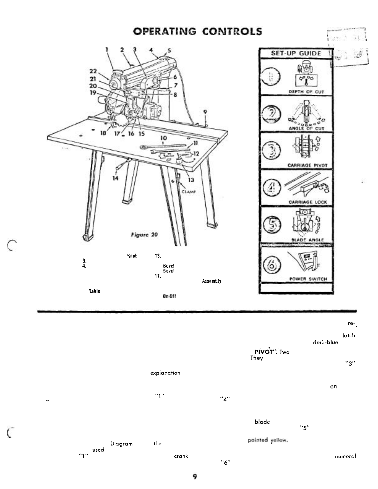
1.
Arm Latch Lever
2.
Swivel
Latch Pin Knoh
3.
Rip Scale lndicator
4.
Radial
Arm Indicator
5.
Radial
Arm Scale
6.
Carriage Lock
Knob
7.
Yoke Clamp Handle
8.
Switch
Lock
and
Key
9.
Table
Clamp
10.
Arbor Wrench
11.
Shaft Wrench
12.
Allen Wrenches
13.
Adapter Plug
14.
Elevation Crank
15.
Eevel lndex Indicator
16.
Bevel
lndex
Scale
17.
Bevel
Lock Knoh
18.
Anti-Kickback
Pawl
Assemhly
19.
Bevel
lndex Handle
20.
Latch
Pin
Handle
21.
On.Cff
Switch
22.
Arm Latch Handle
Figure
21
SET-UP
GUIDE
A
combined number and color code system, designated as
a
"
SET-UP GUIDE", has been applied to the saw in order
to simplify the location
of
tontrols required for a particular
set
-
up operation. The "SET-UP GUIDE
"
is
both a conveni
ence and safety measure, particularly for inexperienced
operators., The operator should become familiar with this
feature before operating the saw.
A
brief explanotion of
the
"
SET-UP GUIDE" is as follows: (See figure
21.)
1.
Notice the radial arm trim strip, the forward end of
which contains six diagrams numbered
"1"
through
..
6".
Each number
is
in a colored circle, and a corres
ponding number in an identical colored circle will be
an the particular operating control member involved.
2.
Locate each control and become familiar with its oper
ation.
a.
"
DEPTH
OF
CUT".
Diagram shows
:he
elevation
crank which
is
used to raise and lower the
blade.
The
numeral
"1"
in a light-blue circle
is
on the crank
handle.
b.
"
ANGLE
OF
CUT".
Two controls 'are involved in re-.
leasing, securing and indexing the angle of the radial
arm. These are: arm latch handle and arm
latch
lever. The handle
is
marked with a dot:-blue circle.
c.
"
CARRIAGE
PIVOT".
'TWO
controls are used in this
operation.
They are: swivel latch knob and yoke
clamp handle, each marked with the numeral
"3"
in an orange circle.
d.
"
CARRIAGE
LOCK".
The carriage lock knob
is
rotated clockwise to secure the carriage on radial
arm, and counterclockwise to release it. The numeral
"4"
in a green circle
is
at the center of the knob.
e.
"
BLADE
ANGLE".
The two controls used in angular
positioning and indexin
g
of the motor to provide the
desired saw
blade angle are: bevel lock knob and
latch pin handle. The numeral
"5"
in a yellow circle
is
attached to the bevel lock knob. The latch pin
handle
is
painted yellow.
f.
"
POWER
SWITCH". This switch
is
located in the
upper left area of the carriage and has the
numeral
"6"
in a red circle directly under it.
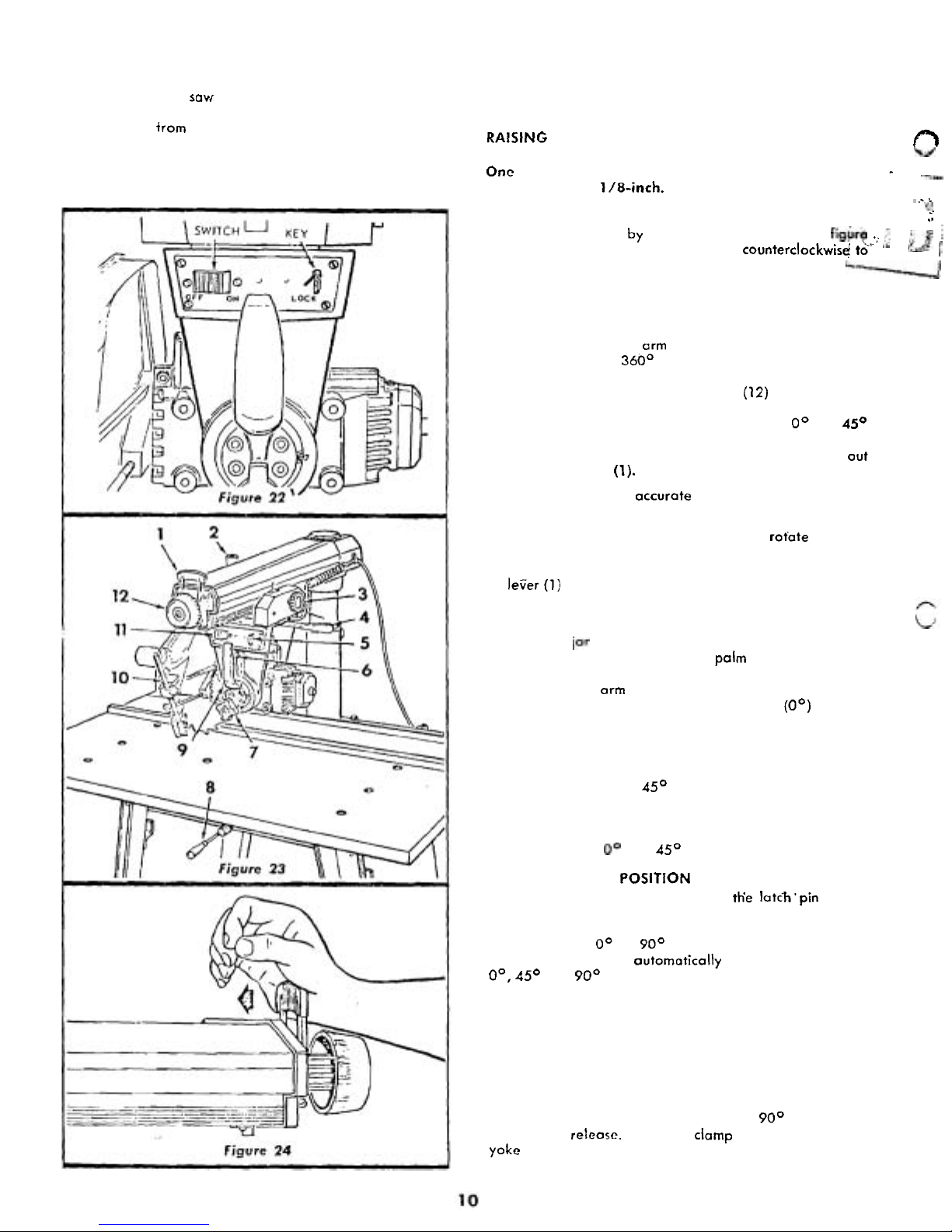
USE OF
KEY
AND SWITCH
NOTE: This
savt cannot be operated without
the key, and likewise, the key cannot be re
moved trom the lock while the sow motor is
running. This feature was designed into your
saw for safety and protection.
1.
Insert key
in
slot and turn it. (See figure 22.)
2.
Press the right-hand side of toggle switch lever to turn
the saw
ON.
Press left-hand side of switch to turn
saw
OFF.
RAISING
AND
LOWERING
THE
RADIAL ARM
This
is
accomplished by the elevation crank
(8,
figure
23).
r"l
kd
One complete turn of this handle will raise or lower
-
---
the radial arm 1/8-inch.
:
..
i
.
t&
LOCKING THE CARRIAGE TO THE RADIAL
ARM
.
.
.
..
.
.
.
...
.
.
..
This is accomplished by the carriage lock knob
(3,
fig"rb
.;
;-,tf
23). Turn the knob clockwise to lock; counterclockwisq! tb'
''
unlock.
&-I
ANGULAR MOVEMENT AND LOCKING
OF
RADIAL
ARM
These movements are controlled by the arm latch lever
(1,
figure 23) and the arm latch handle (12). The radial
arm can be rotated
360° and locked in any position. The
arm
is
unlocked from any position by a slight counterclock
-
wise rotation of the arm latch handle (12) and is locked
in any position by rotating the arm latch handle clockwise
until tight. The radial arm has positive stops at
O0
and 45O
left and right, and is released from these index positions
by unlocking the arm latch handle (12) and pulling
out
the arm latch lever
(1).
For most positive and accurate settings at the index posi
-
tions, the following
is
recommended:
1. If the radial arm is already indexed,
rotate the arm
latch handle (12, figure 23)
1/4
turn counterclock
wise from the locked position, pull out the arm latch
lever
(1)
and move the radial arm off the index position.
Release the arm latch lever
(1).
2.
Move the radial arm into the index position (do not
bump or
jar it) and push on the handle (12) or arm
latch lever (1) solidl
y
with the palm of the hand. (See
figure
24).
This
is
very important as it insures proper
seating of the
arm lock pin in the arm latch, thus always
returning the arm to the correct cross
-
cut (0°) position.
3.
Lock the radial arm by rotating the arm latch handle
(12, figure 23) clockwise until tight.
CAUTION: When moving the radial arm in any
direction beyond
4S0 left or right, always pull
out the arm latch lever (at end of radial arm)
to prevent damaging the arm lock pin.
If
dam
age occurs, the radial arm will not index
properly at
0'
and 4S0 positions (left to right).
MOVEMENT
AND
POSITION OF MOTOR
IN
YOKE
These movements are controlled by
th'e latch'pin handle
(6,
figure 23) and bevel lock knob (7). The bevel scale
indicates the angular position
of
the motor with respect
to
horizontal from
O0
to 90° in either vertical position. The
latch pin handle
(6)
outornotically indexes the motor at
0°,
45O and 90° up and down. Lift the latch pin handle to
release. At any other position, the latch pin handle
is
not
engaged. The bevel lock knob (7) locks the motor to the
yoke when the motor is in any position. Rotate it clockwise
to lock; counterclockwise to unlock.
MOVEMENT
AND
POSITION
OF
THE YOKE
These are controlled by the swivel latch pin knob
(2,
figure
25)
and the yoke clamp handle (4). The swivel latch pin
automatically indexes the yoke at each
90° position.
Lift
the knob to release. The yoke clamp handle
(4)
locks the
yokc to the carriage in any position. Pull the handle to
release. Push
it
to tighten.
 Loading...