

Page 1
SAVE THIS MANUAL
FOR FUTURE
REFERENCE
owners
manual
MODEL NO.
113.244513
Serial
Number
___________________
Model and serial
number may be found
at the right-hand side
of the frame.
You should record both
model and serial
number in a safe place
for future use.
CAUTION:
Read GENERAL and
ADDITIONAL SAFETY
INSTRUCTIONS
carefully
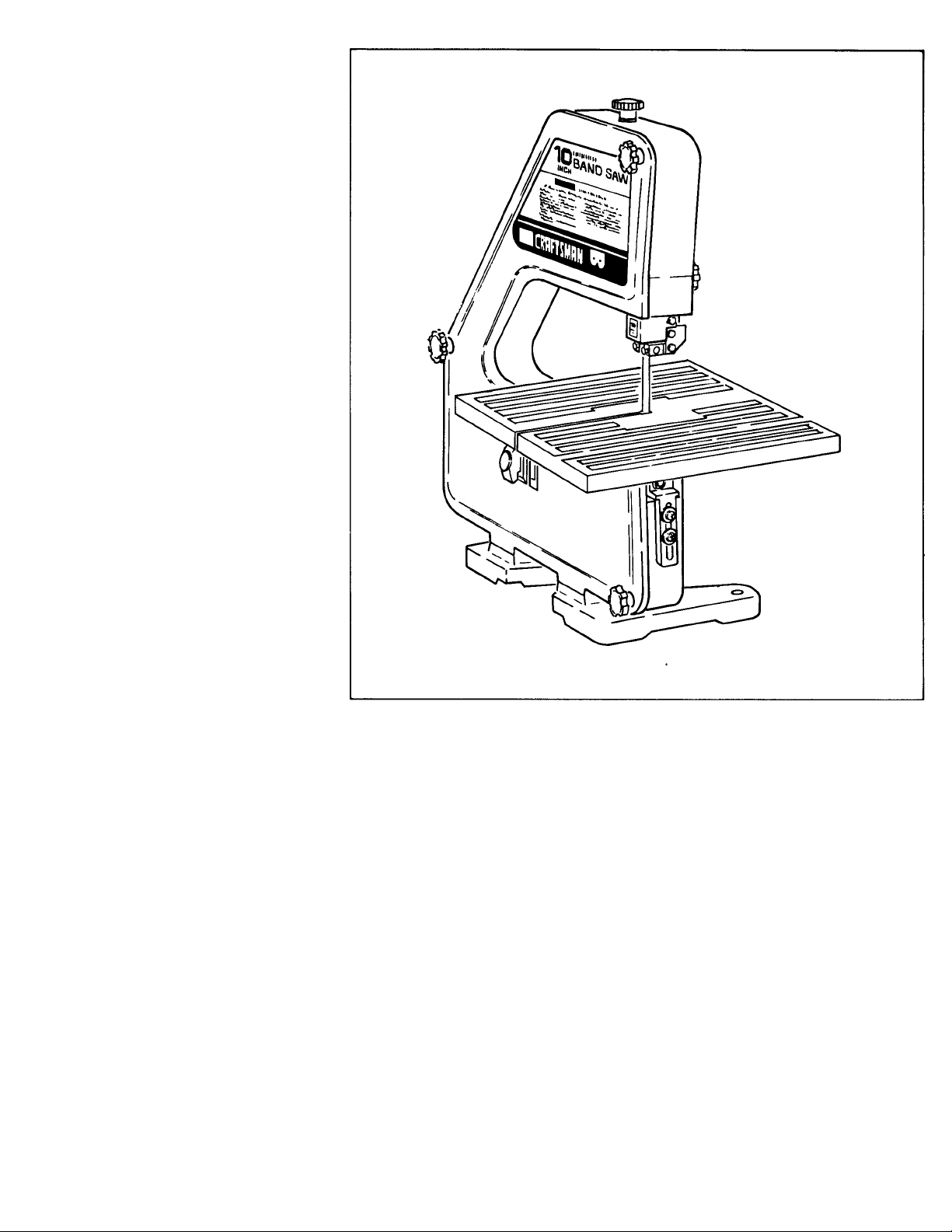
CRRFTSMRN
10-INCH
BAND SAW
• assembly
• operating
• repair parts
Sold by SEARS, ROEBUCK AND CO., Chicago, IL. 60684 U.S.A.
Part No. SP51C0
Page 2

FULL ONE YEAR WARRANTY ON CRAFTSMAN BAND SAW
If within one year from the date of purchase, this Craftsman Band Saw fails due to a defect in
material or workmanship, Sears will repair it, free of charge.
WARRANTY SERVICE IS AVAILABLE BY SIMPLY CONTACTING THE NEAREST SEARS SERVICE
CENTER/DEPARTMENT THROUGHOUT THE UNITED STATES.
THIS WARRANTY APPLIES ONLY WHILE THIS PRODUCT IS USED IN THE UNITED STATES.
This warranty gives you specific legal rights, and you may also have other rights which vary from
state to state.
SEARS, ROEBUCK AND CO., 698/731A, Sears Tower, Chicago, IL 60684
general safety instructions for power tools
1. KNOW YOUR POWER TOOL
Read and understand the owner’s manual and
labels affixed to the tool. Learn its application
and limitations as well as the specific potential
hazards peculiar to this too'.
2. GROUND ALL TOOLS
This tool is equipped with an approved 3conductor cord and a 3-prong grounding type
plug to fit the proper grounding type receptacle.
The green conductor in the cord is the ground
ing wire. Never connect the green wire to a live
terminal.
3. KEEP GUARDS IN PLACE
— in working order, and in proper adjustment
and alignment.
4. REMOVE ADJUSTING KEYS AND WRENCHES
Form a habit of checking to see that keys and
adjusting wrenches are removed from tool
before turning it on.
5. KEEP WORK AREA CLEAN
Cluttered areas and benches invite accidents.
Floor must not be slippery due to wax or saw
dust.
6. AVOID DANGEROUS ENVIRONMENT
Don’t use power tools in damp or wet locations
or expose them to rain. Keep work area well
lighted. Provide adequate surrounding work
space.
7. KEEP CHILDREN AWAY
All visitors should be kept a safe distance from
work area.
8. MAKE WORKSHOP CHILD-PROOF
— with padlocks, master switches, or by re
moving starter keys.
9. DON’T FORCE TOOL
It will do the job better and safer at the rate for
which it was designed.
10. USE RIGHT TOOL
Don’t force tool or attachment to do a job it was
not designed for.
11. WEAR PROPER APPAREL
Do not wear loose clothing, gloves, neckties or
jewelry (rings, wristwatches) to get caught in
moving parts. NONSLIP footwear is recom
mended. Wear protective hair covering to con
tain long hair. Roll long sleeves above the
elbow.
12. USE SAFETY GOGGLES (Head Protection)
Wear safety goggles (must comply with ANSI
Z87.1) at all times. Everyday eyeglasses only
have impact resistant lenses, they are NOT
safety glasses. Also, use face
cutting operation is dusty, and ear protectors
(plugs or muffs) during extended periods of
operation.
or dust mask if
13. SECURE WORK
Use clamps or a vise to hold work when practi
cal. It's safer than using your hand, frees both
hands to operate tool.
14. DON’T OVERREACH
Keep proper footing and balance at all times.
15. MAINTAIN TOOLS WITH CARE
Keep tools sharp and clean for best and safest
performance. Follow instructions for lubricating
and changing accessories.
16. DISCONNECT TOOLS
before servicing; when changing accessories
such as blades, bits, cutters, etc.
17. AVOID ACCIDENTAL STARTING
Make sure switch is in “OFF” position before
plugging in.
18. USE RECOMMENDED ACCESSORIES
Consult the owner’s manual for recommended
accessories. Follow the instructions that
accompany the accessories. The use of im
proper accessories may cause hazards.
19. NEVER STAND ON TOOL
Serious injury could occur if the tool is tipped
or if the cutting tool is accidentally contacted.
Do not store materials above or near the tool
such that it is necessary to stand on the tool to
reach them.
20. CHECK DAMAGED PARTS
Before further use of the tool, a guard or other
part that is damaged should be carefully check
ed to ensure that it will operate properly and
perform its intended function. Check for align
ment of moving parts, binding of moving parts,
breakage of parts, mounting, and any other con
ditions that may affect its operation. A guard or
other part that is damaged should be properly
repaired or replaced.
21. NEVER LEAVETOOL RUNNING UNATTENDED
Turn power off. Don’t leave tool until it comes to a
complete stop.
Page 3

additional safety instructions for band saw
Safety is a combination of common sense, staying alert.
and knowing how your band saw works.
BEFORE USING THE SAW:
WARNING: TO AVOID MISTAKES THAT COULD
RESULT IN SERIOUS, PERMANENT INJURY,
DO NOT PLUG THE SAW IN UNTIL THE FOLLOW
ING STEPS HAVE BEEN SATISFACTORILY
COMPLETED:
1. Assembly and alignment.
2. Learn the function and proper use of the on-off
switch, upper blade guide, lock knob, lower blade
guide, tension adjusting knob, table lock knobs,
bevel scale, guide, bar lock knob, and blade thrust
bearing adjustment.
3. Read and understand an sa‘etv instructions and
operating procedures throughout the manual.
4. Read the tollovv'ing labeis .vh cn appear on the front
of the band saw ana o^aoe oua'd
DANGER
READ AND UNDERSTAND OWNER S MANUAL BEFORE OPERA^NGTHtS MACHINE:
1 ALWAYS WtAR SAFE"^ 30GG.ES »EB »*.5- П' ' »' *.
nWES WHEN O«>ERAnw0 HAOi>NE
2 BE POSmVE THE SAW BlAOE S iNS’A.-EC
TEETH WOiNT>WO XJWVWAftC 'CwAOC "iE B. E BEFOWE ОРЕЯАЛМО MACHINE
3 BE SUWE Blade BlA&E SJC-ES -ho.s-
BEABHtOS АПЕ aD^uS'E; BE'CPE r^EPlMACHINE
4 ALWAYS ADs'VS'' JJIDE SC ' ,.S* Г.ЕАО-
WOWIC PIECE
FOR YOUR OWN SAFETY;
; 1«>«иСЕ i»woeY POTENTIAL Of CONTACT WITH BLAOE
! MAINTAIN CONTROL OF THE WORKPIECE AT AU TIMES—
• BE A’TttrnVE TO ТНШ CITT-OFF PIECES HnnNO EMOOf
IDANGERI
5 TCP
BEFORE
ADJUSTING
6’ KEEPINC FINGERS A SAFE OISTAMCE AWAY
-ОАЭ RRMLY AGAINST THE TABLE
IN INSERT OR JAMWMQ IN SLOT ALLOW BLAOE TO
S'OP BEFORE REWOV1NC JAMMED ИЕСЕ
WHEN INSTALLING OR MOVING THE SAW
1. To avoid injury ‘'em unexpected saw movement:
a. Bolt or clamp the saw to a sturdy level workbench
or stand whe-e there is plenty of room for feeding
the workpiece
b. Adjust the saw so the table is level and the saw
does not rocK
c. Bolt the bench or' stand to the floor if it tends to
slip, slide, or tip over during operations like cutting
long, heavy ooai'ds
d. Turn saw off and unplug electric cord before mov
ing the saw to a new area.
2. Store and use the band saw indoors.
BEFORE EACH USE
1, Inspect your saw. If any part of this band saw is
missing, or bent, or failed in any way, or any electrical
components do not work properly, turn the saw off,
mmove switch key. and unplug the saw. Replace
damaged, missing, or failed parts before using the
sa.v again.
2, = a- ,our work to protect your eyes, hands, face,
ea-; aw:: body.
a. Do not do layout, assemble, or set up work on
the table while the saw is running.
b. Wear safety goggles (not glasses) that comply
with ANSI Z87.1 (shown on package). Using any
power tool can result in foreign objects being
thrown into the eyes, which can result in perma
nent eye damage. Safety goggles are available
at Sears retail or catalog stores. Use of glasses
or use of goggles not in compliance with ANSI
Z87.1 could result in severe injury from breakage
of the eye protection.
К FORESIGHT IS
" BEHERTHAN
NO SIGHT
c. For dusty operations, wear a face shield along
with safety goggles.
d. Use extra caution with large, very small, or awk
ward workpieces,
1. Use extra supports (tables, saw horses, etc.)
for any workpieces large enough to tip when
not held down to the table top.
2. Do not feed small pieces that require your
finger holding the workpiece to go under the
guard area. Use jigs or fixtures to hold the
work and keep yours hands away from the
blade.
3. When cutting irregularly shaped workpieces,
plan your work so it will not pinch the blade.
A piece of molding, for example, must lay flat
or be held by a fixture or jig that will not let it
twist, rock or slip while being cut.
4. Properly support round material such as
dowel rods, or tubing. They have a tendency
to roll while being cut, causing the blade to
“bite." To avoid this, always use a “V” block,
or clamp the workpiece to a miter gauge.
e. To avoid risk of hearing damage, wear ear plugs
or muffs during extended periods of operation.
f. To avoid being suddenly caught in the blade:
1. Do not wear gloves.
2. Remove all jewelry and loose clothing.
3. Tie back long hair.
4. Roll long sleeves above the elbow.
g. To avoid injury from accidental starting, always
unplug saw, turn switch off and remove switch
key before removing the guard, installing or re
moving any blade, accessory or attachment, or
making any adjustments.
h. To avoid slips and jams causing injury:
1. Choose the right size and style blade for the
material and the type of cutting you plan to
do. Use this band saw to cut only wood, wood
like products and plastic.
Page 4

2. Make sure the blade teeth point downward
toward the table.
3. Make sure the blade tracking guides and
thrust bearings are properly adjusted.
4. Always check and correctly adjust blade
tension.
I. To avoid accidental blade contact, minimize blade
breakage and provide maximum blade support.
1. Always adjust the upper blade guide and blade
guard to just clear the workpiece.
2. Plan your hand placement so your fingers will
not be where a sudden slip could cause them
to hit the blade.
j. Make sure all clamps and knobs are tight and
there is no excessive play in any parts.
k. To avoid an electrical shock, make sure your fin
gers do not touch the metal prongs on the plug
when installing or removing the plug to or from
a live outlet.
l. Never turn your band saw “ON” before clearing
everything except the workpiece and related feed
or support devices off the table.
WHENEVER SAW IS RUNNING
WARNING: DO NOT ALLOW FAMILIARITY (GAINED
FROM FREQUENT USE OF YOUR BAND SAW) TO
CAUSE A CARELESS MISTAKE. ALWAYS RE
MEMBER THAT A CARELESS FRACTION OF A SEC
OND IS SUFFICIENT TO INFLICT SEVERE INJURY.
a. If your saw makes an unfamiliar noise or if it
vibrates excessively, stop immediately. Turn the
saw off. Remove switch key and unplug the saw.
Do not restart until finding and correcting the
problem.
b. Avoid awkward hand positions where a sudden
slip could cause a hand to move into the blade.
c. Feed the workpiece only fast enough to let the
blade cut without bogging down or binding.
d. Before freeing jammed material, turn saw off. Re
move switch key. Remove plug from power
source outlet. Wait for all moving parts to stop.
e. When backing up the workpiece, the blade may
bind in the kerf (cut). This is usually caused by
sawdust clogging up the kerf or because the
blade comes out of the guides. If this happens:
1. Turn saw off.
2. Unplug saw.
3. Remove switch key.
4. Wait for all moving parts to stop.
5. Remove band saw cover.
6. Stick a flat blade screwdriver or wedge into
the kerf.
7. Turn the upper wheel by hand using your palm
while backing up the workpiece.
f. Before removing loose pieces from the table, turn
saw off and wait for all moving parts to stop.
g. To avoid injury from untested or improper acces
sories, use only Recommended Accessories
listed on the Accessory page of this manual.
glossary of terms for woodworking
Beveling
An angle cutting operation through the face of the board.
Crosscut
A cutting operation made across the width of the
workpiece.
Compound Cutting
A simultaneous bevel and miter cutting operation.
FPM
Feet per minute. Used in reference to surface speed
of blade.
Freehand (as used for band saw)
Performing a cut without the workpiece properly sup
ported on the work table.
Gum
A sticky, sap-based residue from wood products.
Kerf
The material removed by the blade In a through cut or
the slot produced by the blade in a non-through or
partial cut.
Leading End
The end of the workpiece which is pushed into the
cutting tool first.
Mitering
An angle cutting operation made across the width of
the workpiece.
Push Stick
A device used to feed the workpiece through the saw
during narrow ripping type operations so the operator’s
hands are kept well away from the blade.
Resaw
A cutting operation to reduce the thickness of the work
piece to make thinner pieces.
Resin
A sticky, sap-based substance that has dried.
Ripping
A cutting operation along the length of the workpiece.
Sawblade Path
The area of the worktable or workpiece directly In line
with the saw blade.
Set
The distance the tip of the saw blade tooth is bent
outward from the face of the blade.
Trailing End
The workpiece end last cut by the saw blade.
Workpiece
The item on which the cutting operation is being per
formed. The surfaces of a workpiece are commonly
referred to as faces, ends, and edges.
Worktable
The surface on which the workpiece rests while perform
ing a cutting operation.
Page 5
motor specifications and eiectrical requirements
This machine is designed to use, and is equipped with,
a 1725 RPM motor. It is wired for operation on 120 volts,
60 Hz., alternating current. (TOOL MUST NOT BE CON
VERTED TO OPERATE ON 230 VOLT).
For replacement motor refer to parts list in this
manual.
CONNECTING TO POWER SUPPLY OUTLET
This machine must be grounded while in use to
protect the operator from electric shock.
Plug power cord into a 120V properly grounded type
outlet protected by a 15-amp. fuse or circuit breaker.
If you are not sure that your outlet is properly
grounded, have it checked by a qualified electri
cian.
WARNING: DO NOT PERMIT FINGERS TO
TOUCH THE TERMINALS OF PLUGS WHEN
INSTALLING OR REMOVING THE PLUG TO OR
FROM THE OUTLET.
WARNING: IF NOT PROPERLY GROUNDED
THIS POWER TOOL CAN CAUSE AN ELECTRI
CAL SHOCK PARTICULARLY WHEN USED IN
DAMP LOCATIONS CLOSE TO PLUMBING. IF
AN ELECTRICAL SHOCK OCCURS THERE IS
THE POTENTIAL OF A SECONDARY HAZARD
SUCH AS YOUR HANDS CONTACTING THE
SAW BLADE.
If power cord is worn or cut, or damaged in any
way, have it repiaced immediately.
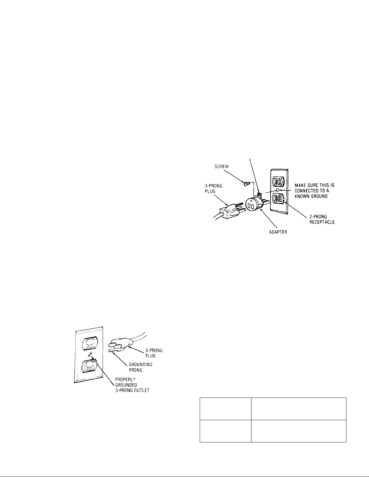
Your unit is for use on 120 volts, and has a plug that
looks like below.
This plug requires a mating 3-conductor ground
ed type outlet as shown.
If the outlet you are planning to use for this
power tool is of the two prong type, DO NOT
REMOVE OR ALTER THE GROUNDING PRONG
IN ANY MANNER. Use an adapter as shown
below and always connect the grounding lug to a
known ground.
It is recommended that you have a qualified elec
trician replace the TWO prong outlet with a pro
perly grounded THREE prong outlet.
GROUNDING LUG
An adapter as illustrated is available for connect
ing plugs to 2-prong receptacles. The green
grounding lug extending from the adapter must
be connected to a permanent ground such as to
a properly grounded outlet box.
NOTE: The adapter illustrated is for use only if
you already have a properly grounded 2-prong
receptacle. Adapter is not allowed in Canada by
the Canadian Electrical Code.
This power tool is equipped with a 3-conductor
cord and grounding type plug which has a
grounding prong, approved by Underwriters’
Laboratories and the Canadian Standards Associ
ation. The ground conductor has a green jacket
and is attached to the tool housing at one end
and to the ground prong in the attachment plug
at the other end.
The use of any extension cord will cause some
loss of power. To keep this to a minimum and to
prevent overheating and motor burn-out, use the
table below to determine the minimum wire size
(A.W.G.) extension cord.
Use only 3 wire extension cords which have 3prong grounding type plugs and 3-prong recep
tacles which accept the tools plug.
Length of the
Conductor
0 - 25 Feet
26 - 50 Feet
51 - 100 Feet
Wire Sizes Required
(American Wire Gage Number)
120V Lines
No. 16
No. 14
No. 12
Page 6
contents
CONTENTS
POWER TOOL WARRANTY
........................................
GENERAL SAFETY INSTRUCTIONS FOR
POWER TOOLS..........................................................2
ADDITIONAL SAFETY INSTRUCTIONS
FOR BAND SAW.........................................................3
MOTOR SPECIFICATIONS AND ELECTRICAL
REQUIREMENTS
UNPACKING AND CHECKING CONTENTS
........................................................
................
ASSEMBLY
Mounting Band Saw to Workbench
Clamping Band Saw to Workbench
Installing the Table
....................................................
.........................
.........................
Installing the Blade....................................................9
Tensioning the Blade
Tracking the Blade
Adjusting the Table Square to Blade
..............................................
..................................................
....................
Adjusting Upper Blade Guide
Assembly................................................................12
Adjusting Upper Blade Guides...............................12
Adjusting Upper Thrust Bearing
............................
Adjusting Lower Blade Guide
Assembly
................................................................
10
11
11
12
12
2
Adjusting Lower Blade Guides
..............................
12
Drive Belt Tension...................................................13
Adjusting Table........................................................13
GETTING TO KNOW YOUR BAND SAW
Tension Adjustment Knob......................................14
Cover Knobs
5
6
Blade Guides
Tension Lock Knob
Guide Bar Lock Knob
............................................................
...........................................................
.................................................
............................................
14
14
14
14
Table Lock Knobs....................................................14
7
8
8
Bevel Scale
On-Off Switch ..........................................................14
BASIC BAND SAW OPERATION
..............................................................
14
Sawing......................................................................15
MAINTENANCE..........................................................16
Lubrication...............................................................16
RECOMMENDED ACCESSORIES............................16
TROUBLESHOOTING ...............................................17
REPAIR PARTS..........................................................18
unpacking and checking contents
TOOLS needed-
MEDIUM SCREWDRIVER
1/2 INCH WRENCH
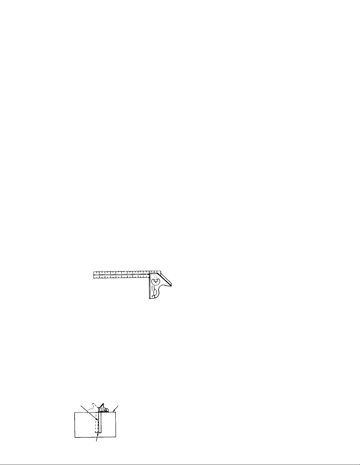
COMBINATION SQUARE MUST BE TRUE
DRAW LIGHT
LINE ON BOARD
ALONG THIS EDGE
combination SQUARE
#2 PHILLIPS SCREWDRIVER
HEX WRENCH
1/8 & 3/16
STRAIGHT EDGE OF
BOARD 3/4" THICK
THIS EDGE MUST BE
PERFECTLY STRAIGHT
WARNING; FOR YOUR OWN SAFETY, NEVER
CONNECT PLUG TO POWER SOURCE OUTLET
UNTIL ALL ASSEMBLY STEPS ARE COMPLETE,
AND YOU HAVE READ AND UNDERSTAND THE
SAFETY AND OPERATIONAL INSTRUCTIONS.
Model 113.244513 Band Saw is shipped complete
in one carton.
Separate all parts from packing materials and
check each item with illustration and "Table of
Loose Parts”. Make certain all items are account
ed for, before discarding any packing material.
WARNING: IF ANY PARTS ARE MISSING, DO NOT
TRY TO ASSEMBLE THE BAND SAW, PLUG IN THE
POWER CORD, OR TURN THE SWITCH ON UNTIL
THE MISSING PARTS ARE OBTAINED AND IN
STALLED CORRECTLY.
SHOULD BE N0 GAP OR OVERLAP HERE WHEN
SQUARE IS FLIPPED OVER IN DOTTED POSITION
Page 7

assembly
ITEM
A
B
C
D
TABLE OF LOOSE PARTS
Basic saw assembly
Owners Manual
Saw Table assembly
...............................
.......................................
...............................
Bag Assembly Part #69181
Containing the following parts:
Switch, Key
Nut, Wing i/4-20
Screw, Truss Hd. 1/4-20 x 3/4
Washer 17/64 x 5/8 x 1/16
Washer 17/64 x 47/64 x 1/16
..............................................
................................................
.................
.......................
................
Indicator, Bevel ...............................
Screw, Pan Cross 10-24 x 1/4
Insert, Table
Knob.....................................
................................
...........
QTY.
1
1
1
1
1
1
1
2
1
1
1
2
MOUNTING BAND SAW TO WORKBENCH
If band saw is to be used m a permanent loca
tion, it should be fastened securely to a firm sup
porting surface such as a workbench.
If mounting to a workbench, holes should be
drilled through supporting surface of the work
bench using dimensions illustrated.
1. Each leg should be bolted securely using
5/16" dianneter machine screws, lockwashers,
and 5/16" hex nuts (not included). Screw
length should be V2" plus the thickness of
the bench too.
2. Locate and marK the holes where band saw is
to be mounted.
3. Drill (4) 3 8 diameter holes through work
bench.
4. Place band saw on workbench aligning holes
in feet with holes drilled in workbench.
5. Insert all four 516" screws and tighten.
An alternate method of mounting is to fasten
band saw to a mounting board. The board should
be of sufficient size to avoid tipping of saw while
in use. Any good grade of plywood or chipboard
with a 3/4" minimum thickness is recommended.
(Thinner chipboard can break.)
NOTE: Front two mounting bolts should be
inserted from the bottom with washer and nut on
top.
.-f
6-V16"
■f
3/8" DIAMETER
(41 HOLES
10-13/16"
1. Follow instructions for mounting to work
bench, substituting a board 18" x 24" mini
mum size and using 5/16 inch flat head
screws, lockwashers, and hex nuts (not in
cluded). Screw length should be 1V2" plus
the thickness of the mounting board.
NOTE; For proper stability, holes must be
counter sunk so screw heads are flush with the
bottom surface of supporting board.
Page 8

assembly
2. Securely clamp board to workbench using
“C” clamps.
NOTE: Supporting surface where band saw is
mounted should be examined carefully after
mounting to insure that no movement during use
can result. If any tipping or walking is noted,
secure workbench or supporting surface before
operating band saw.
CLAMPING BANDSAW TO WORKBENCH
The Band Saw can be clamped directly to a
workbench using two (2) or more “C” clamps on
base of unit.
INSTALLING THE TABLE
Apply a coat of automobile wax to the table top
and inside surfaces of trunnion that slide on
frame.
1. Loosen the guide bar lock knob and position
the upper guide assembly all of the way up.
Tighten lock knob.
2. Locate two (2) knobs and two (2) 17/64 x
47/64 X 1/16 washers in loose parts bag, and
the table assembly in loose parts.
3. Place table assembly onto band saw frame
with thè trunnion against mounting rib in
frame.
GUIDE BAR
LOCK KNOB
UPPER
GUIDE
ASSEMBLY
TRUNNION'
Hold table assembly against the frame and
install two (2) table lock knobs and washers
as shown through the trunnion slots and
tighten.
BAND SAW
FRAME
TABLE LOCK
KNOBS
Page 9

5. Locate bevel indicator and 10-24x1/4 pan
cross hd. screw in loose parts bag.
6. Install bevel indicator and screw as shown
using a Phillips screwdriver.
NOTE: This unit comes with the Band Saw blade
installed, assembly continues on p. 10, “Tension
ing the Blade.”
REPLACING THE BLADE
1. Loosen the guide bar lock knob and position
the upper guide assembly approximately one
inch above the table and tighten lock knob.
2. Loosen the two blade guard mounting screws
and remove the blade guard.
3. Loosen the guide bar lock knob and position
the upper guide assembly approximately two
inches above the table as shown and tighten
the lock knob.
4. Remove table insert, truss head screw, wash
er and wing nut from the table (See Assem
bly, p. 13 - "Adjusting the Table”). Replace
these parts after the blade is installed, ten
sioned and tracked.
5. Loosen the two screws in the front of the
upper blade guide assembly that secure the
blade guides and separate them about 1/8".
GUIDE BAR
LOCK KNOB
UPPER GUIDE
ASSEMBLY
6. Loosen the two screws in the side of the
upper guide assembly and slide guides and
thrust bearing all of the way back.
7. Tighten all screws.
Loosen the three (3) cover knobs by turning
counterclockwise and remove cover.
NOTE: Replace the bandsaw cover after blade is
properly installed, tensioned and tracked.
COVER
KNOBS
BLADE
GUIDE
FRAME
Page 10

assembly
9. Loosen the two screws that secure the lower
blade guides and separate them about 1/8".
10. Loosen the screw holding the lower blade
guide support and slide support all the way
toward the rear of the saw, and retighten all
screws.
WARNING: TO AVOID BEING SCRAPED
SHOULD BLADE SUDDENLY UNCOIL, WEAR
SAFETY GOGGLES AND CAREFULLY UNCOIL
THE BLADE HOLDING IT AT ARMS LENGTH.
11. Place the blade over the wheels with the
teeth pointing downward toward the table as
shown. Make sure the blade is in the center
of the rubber tires.
NOTE: Your bandsaw can use 1/8 or 1/4 inch wide
blades, 56-7/8 inches long. A 1/4 inch blade is included
with this saw.
TENSIONING THE BLADE
The bandsaw is equipped with a self-limiting
tension device. The tension is factory set and
should not need adjustment. The blade must be
installed before tension can be set.
1. Turn tension adjustment knob until knob
contacts washer and sleeve.
TENSION WHEEL
TENSION
ADJUSTING
KNOB
BLADE
SLOT IN TABLE
DRIVE WHEEL
IDLER WHEEL
2. DO NOT turn knob after contact is made and
resistance if felt. This is the proper tension
setting for a 1/4” blade.
3. To release tension turn knob counterclock
wise until knob is above the washer and
sleeve.
COMPENSATION FOR WEAR
Tension screw is provided to make minimal
adjustments due to wear. The tension screw
creates a drag between the wheel guide and the
frame.
1. Remove the blade before adjusting.
2. Use a phillips screw driver to adjust the ten
sion screw. Turn clockwise to increase the
drag (tension).
3. Check tension by lifting up on tension knob. If the
tension knob will not move the tension screw is too
tight. Adjust by turning tension screw coun
terclockwise and recheck.
WARNING: OVER TENSION AND FAILURE TO
PROPERLY SET BLADE GUIDES AND THRUST
BEARING WILL CAUSE PREMATURE BLADE
BREAKAGE. FOLLOW ADJUSTING BLADE
GUIDE ASSEMBLIES COMPLETELY TO HELP
MAINTAIN NORMAL BLADE LIFE.
10
Page 11

TRACKING THE BLADE
Tension knob must be tightened before tracking
biade.
1. Turn the upper wheel by hand (clockwise)
and check if the blade remains in the approx
imate center of the tires. If the blade moves
away from the center of the tires, while you
are turning the wheels, adjust as follows:
A. Turn the tracking adjustment set screw
slightly with a 1/8” hex wrench. (Turning
the set screw moves the tension wheel back
and forth.)
B. If the blade moves toward the front of the
band saw:
Turn the tracking adjustment screw clock
wise about 1/4 of a turn, as though you
were tightening it.
If the blade moves toward the back of the
band saw:
Turn the tracking adjustment screw
counterclockw se about 1/4 of a turn as
though you were loosening it.
TENSION
blade to run in the approximate center of
all tires.
C. After adjusting, turn upper wheel by hand
clockwise a few turns and notice if the
blade remains in the approximate center of
the tires, readjust if necessary, until blade
TRACKING ADJUSTMENT
SET SCREW
NOTE: When table is tilted to a bevel angle, the
lower blade guide support should be lowered to
clear the table. After bevel cutting and returning
table to zero position, always raise the lower
blade guide up to provide maximum support for
the blade.
11
Page 12

assembly
NOTE: The upper and lower blade guides support
the blade and keep it from twisting during opera
tion. An adjustment is necessary when blades
are changed, replaced or installed for the first
time.
ADJUSTING UPPER BLADE GUIDE ASSEMBLY
1. Loosen lower screw on side of upper blade
guide assembly and slide assembly forward
until the front edge of the blade guides are
approximately 1/32" from the GULLET of the
saw blade. Tighten screw.
ADJUSTING UPPER BLADE GUIDES
GULLET
1. Loosen the two screws that lock the upper
blade guides and press the two guides evenly
against the sides of the blade but do not
pinch the blade. Release the guides and ro
tate the upper wheel slightly clockwise mov
ing the blade downward. Make sure one
guide is not further away from the blade than
the other. Tighten both screws.
ADJUSTING UPPER THRUST BEARING
NOTE: The thrust bearing supports the blade
from the rear and will rotate when the blade is
pushed against it while you are cutting. As soon
as you stop cutting, the bearing should stop
rotating.
1. To adjust, loosen the upper screw on the side
of the upper blade guide assembly and slide
the bearing forward until it is approximately
1/32" from the back of the blade. Tighten
screw. Rotate upper wheel slightly clockwise
to check clearance. Readjust if necessary.
ADJUSTING LOWER BLADE GUIDE ASSEMBLY
® o
SAW
BLADE
SL AD E
GUIDES
1. Loosen the screw (as shown) on the side of
the lower blade guide assembly and slide
assembly forward until bearing is approxi
mately 1/32" from the back of the blade.
Blade guides will align with this adjustment.
Tighten screw.
ADJUSTING LOWER BLADE GUIDES
1. Loosen the two screws that lock the lower
blade guides and press the two guides evenly
against the sides of the blade but do not
pinch the blade. Release the guides and ro
tate the upper wheel slightly clockwise mov
ing the blade downward. Make sure one
guide is not further away from the biade than
the other. Tighten both screws.
NOTE: After all adjustments have been made,
turn the upper wheel by hand (clockwise) a few
turns to check blade travel and clearance.
12
Page 13

DRIVE BELT TENSION
WARNING: TO AVOID INJURY DUE TO ACCI
DENTAL START, UNPLUG TOOL BEFORE
MAKING ADJUSTMENTS.
The tension on the drive belt has been set at the
factory. If adjustment is needed, use a 3/16” hex
wrench to loosen upper and lower cap screws.
Pull motor away from drive wheel to apply proper
tension to drive belt. Retighten cap screw while
holding motor in place.
ADJUSTING THE TABLE
1. Replace the blade guard on the upper assem
bly and tighten screws,
2. Locate the table insert and place it in the
opening in the table. Align slot in the insert
with the slot in the table,
3. Locate a 1/4 ■ 20 x 3 4 " truss head screw, a
flat washer, a'^c a 1 4 ■ 20 wing nut in loose
parts. Insert sce.v into hole in table top as
illustrated.
4. From the underside of the table, install wash
er and w -^g ■'ut onto the truss head screw
and tighten hnger tight. This will keep the
table flat and in alignment.
5. Replace tne oand saw cover.
getting to know your band saw
TRACKING ADJUSTMENT
Page 14

getting to know your band saw
1. Tension adjusting knob... Tightening the
knob (clockwise) will increase the tension on
the blade. Loosening it (counter clockwise)
will decrease the tension. (Tension lock knob
must be released).
2. Cover knobs ... Secure cover to frame by
tightening all three (3) cover knobs.
3. Blade Guides . . . Supports the blade and
keeps it from twisting during operation. An
adjustment is necessary when blades are
changed or replaced.
4. Tension screw . . . maintains tension be
tween upper wheel guide and frame.
ON-OFF SWITCH. The On-Off Switch has a
8.
locking feature. THIS FEATURE IS INTEND
ED TO HELP PREVENT UNAUTHORIZED
AND POSSIBLY HAZARDOUS USE BY
CHILDREN AND OTHERS.
1. To turn machine on
switch.
insert key into
5. Guide bar lock knob . . . The upper blade
guide assembly should just clear the work
piece while cutting. Always adjust the upper
guide assembly and lock the guide bar by
tightening the blade guide lock knob before
turning on the band saw.
6. Table lock knobs . . . Loosening knobs aliows
the table to be tilted and tightening knobs
locks the table in place.
7. Tilt (bevel) scale . . . Shows
tilted for bevel cutting.
degree table is
NOTE: Key is made of yellow plastic; locate in
loose parts bag.
2. Insert finger under switch lever and puil
end of switch out.
3. To turn machine OFF . . . PUSH lever in.
NEVER LEAVE THE MACHINE UNATTENDED
UNTIL IT HAS COME TO A COMPLETE STOP.
4. To lock switch in OFF position . . . hold
switch IN with one hand . . . REMOVE key
with other hand.
WARNING: FOR YOUR OWN SAFETY, ALWAYS
LOCK THE SWITCH “OFF” WHEN MACHINE IS
NOT IN USE ... REMOVE KEY AND KEEP IT IN A
SAFE PLACE ... ALSO ... IN THE EVENT OF A
POWER FAILURE (ALL OF YOUR LIGHTS GO
OUT) TURN SWITCH OFF . .. REMOVE THE KEY
AND STORE IT REMOTE FROM BAND SAW.
THIS WILL PREVENT THE MACHINE FROM
STARTING UP AGAIN WHEN THE POWER
COMES BACK ON. 14
Page 15

basic band saw operation
A band saw is basically a "curve cutting" mach
ine. It is also used for straight-line cutting opera
tions such as cross cutting, ripping, mitering,
beveling, compound cutting, and resawing. It is
not capable of doing inside cutting.
This band saw is designed to cut wood and
wood like products only.
For general type scroll cutting, follow the pattern
lines by pushing and turning the workpiece at
the same time. Do not try to turn the workpiece
while engaged in the blade without pushing it;
the workpiece could bind o’" tw'ist the blade.
A curve cut is best perfo^n^ed by keeping the
pattern line in line wit"^ :"e b^ade while turning
the workpiece before :"e "ac:us of the curve is
cut. The blade
pattern line (saw -e'' s -^ze w-ood cutting band
saw blades are t" "
NOTE: B
for clantv
shou c ¡n
and right hand removed
the middle of the
S.A'.'i
KERF
RIGHT ■ Planning ahead by turning workpiece
for cutting a curve.
WORKPIECE
WRONG ■ Not planning ahead for cutting a
curve could bind or twist blade if workpiece is
forced.
WARNING: ADJUST THE UPPER GUIDE ASSEM
BLY TO JUST CLEAR THE WORKPIECE.
1. Use boi"
blade. H:
Use ge"':
allow the
2. The srTia
determwe
blade w
1-12
i-
Relief cuts a^e ~aoe .‘."en an intricate curve (too
small a racws ‘c- a " -A-mch blade) is to be cut. A
relief cut IS made c,. cutting through scrap sec
tion of workpiece to curve in pattern line, then
carefully backing blade out. Several relief cuts
should be made for intricate curves, then follow
pattern line as sections are cut off of curve
"relieving” blade pressure.
e feeding the work into the
ece firmly against the table.
Do not force the work, but
mle that can be cut out is
of the blade. A 1/4" wide
oiameter of approximately
WORKPIECE
BLADE
PATTERN LINE
NOTE: Blade guard is raised and right hand removed
■: ■ clarity of picture only.
15
Page 16

maintenance
WARNING: FOR YOUR OWN SAFETY, TURN
SWITCH “OFF” AND REMOVE PLUG FROM
POWER OUTLET BEFORE MAINTAINING OR
LUBRICATING YOUR BAND SAW.
TIRES
Pitch and sawdust that accumulate on the tires
should be removed with a stiff brush or scraped
off with a piece of wood. Do not use a sharp
knife or any kind of solvent.
When the tires become worn they should be re
placed. When replacing the tires, put a thin layer
of rubber cement on the outside of the wheels
and inside of the tires. Allow to dry, then slide
tires onto wheels aligning tires inside wheel
edges.
GENERAL
Keep your Band Saw clean.
Remove sawdust from the inside frequently.
Do not allow pitch to accumulate on the table,
blade insert, blade guides, or thrust bearings.
Clean them with Craftsman Gum and Pitch
Remover.
Apply a thin coat of automobile-type wax to the
table so the wood slides easily while cutting.
Also apply wax to the inside surfaces of the
trunnion.
MOTOR/ELECTRICAL
Frequently vacuum or blow out any sawdust from
the motor.
If the power cord is worn, cut, or damaged in any
way, have it replaced immediately.
LUBRICATION
All of the BALL BEARINGS are permanently
lubricated. They require no further lubrication.
RECOMMENDED ACCESSORIES
Item Cat. No.
Miter Gauge.......................................................9-24214
Blades (56-7/8” length)............................See Catalog
Leg Set...............................................................922244
The above recommended accessories are current
and were avaiiable at the time this manual was
printed.
16
Page 17

troubleshooting
WARNING: FOR YOUR OWN SAFETY, TURN
SWITCH “OFF” AND REMOVE PLUG FROM
POWER OUTLET BEFORE READJUSTING OR
ALIGNING YOUR BAND SAW.
TROUBLE
Motor will not run.
Blade does not run in the
approximate center of the
upper wheel.
Band Saw slows down
when cutting.
Blades breaking.
Motor sounds under
load when not cutting.
Blade will not allow for
general straight cutting.
PROBABLE CAUSE
1. Defective On-Off switch.
Defective power or motor cord.
2, Motor Defective.
1. Not tracking properly.
1, Cutting too small a radius.
2. Dull blade.
1. Too much tension.
2. Kink in blade caused by cut
ting too small a radius or turn
ing the material too fast when
cutting.
1. Too much blade tension.
2. Too much belt tension.
1. Blade guides and bearings
not properly adjusted.
REMEDY
1. Replace defective parts before using
Band Saw again.
2. Consult Sears Service. Any attempt to repair
this motor may create a HAZARD unless
repair is done by a qualified service techni
cian. Repair service is available at your near
est Sears Store.
1. Adjust tracking, see Assembly Section,
“Tracking the Blade.”
1. Stop feeding, and back up the material
slightly, until the band saw speeds up.
2. Replace blade.
1. Adjust tension. See Assembly section
“Tensioning The Blade.”
2. Use correct cutting technique. See Basic
Band Saw Operation Section.
1. Adjust blade tension. See Assembly
section “Tensioning The Blade.”
2. Adjust belt tension. See Assembly Section
“Drive Belt Tension.”
1. Adjust upper and lower blade guides and '
bearings. See Assembly section “Adjusting
Upper Blade Guide Assembly.”
2. Defective blade.
2. Replace blade.
17
Page 18

PARTS LIST FOR CRAFTSMAN 10 INCH MOTORIZED BANDSAW
MODEL NO. 113.244513 CD
00
t
Page 19

PARTS LIST FOR CRAFTSMAN 10-INCH MOTORIZED BANDSAW
MODEL NO. 113.244513
ALWAYS ORDER BY PART NO. AND DESCRIPTION-NOT BY KE Y NO
í
CO
Key
No.
1 69165
2 814351
3
4
5 815273
6 815286
7 813930-4 Knob
8 805552-16
9
10 815276
11
12
13 STD502503
14
15
16
17
18
19
20 60256
21 STD551131
22 STD541031
23
24
26
27 69147
28
29 69161
30 STD511003
31 69155
32 815275
33 STD523115
34 STD510603
35 STD551125
36
Part
No.
Ring-Retaininq 5160
Washer-Plastic
69177 Tiro
815613
817131
817132
815279
815476
STD551025
STD512510
69146
69157 Knob
62442
69164 Relief Strain
STD551208
STD510802
69149
60102 Screw-Soc. Cap 1 /4-20 x 1
Whool-ldlor
Shaft-Upper Wheel
Guide-Wheel
Washer 17/64x1 x1/16
Cup-Retainer
Spring
Spacer-Tension
Frame
*Screw-Set Hex Cup
1/4-20x3/8
Washer-Spring
* Washer 17/64 x 47/64 x 1 /16
Screw-Pan HD. 1/4-20x 1
Clamp-Guide Rod
Switch-Locking
Switch-Key
*Lockwasher-5/16
*Nut-Hex 5/16-18
*Lockwasher-Ext. #8
*Screw-Pan HD. 8-32 x 5/16
Cord-Power
Cover-Switch
• Motor (Includes Key #70)
* Screw-Pan Cross 10-24x3/8
Indicator-Bevel
Foot-Frame
*Screw-Hex HD. 5/16-18x1 1/2
* Screw-Pan HD. 6-32x3/8
*Lockwasher-1/4
Description
Key
No.
37 69172
3H
3!)
40 65)1,53
41 1)9174
42 69175
43
44 STD511005
45 STD512507
46 69178 Trunnion
47
48
49 69176
50 803709
51 69173 Support-Upper Guide
52 69152
53 817961
56
57
58
59
60
61
62
63
64
65
66
67
68
69
70
—
Part
No.
Spacer
60528
69169
STD551010
STD541025
69167
60531 Screw-Locking Set 1 /4-20 x 5/8
69156
60532
60530 Screw-Truss HD. 1/4-20x3/4
9414920
STD541625
69160
69145
60533 Ring-Retaining
69148
815614
69168
69144
69162
68076
SP5100
69189
Bearing-Ball
Shaft-Guide Support
Guide
Support-Lower Guide
‘Washer 13/64 x 1/2x3/64
* Screw-Pan Cross 10-24 x 1/2
* Screw-Pan Cross 1 /4-20 x 3/4
* Nut-Hex 1/4-20
Rod-Guide Support
Guard-Blade
Shaft Asm. Bearing
Insert-Table
Screw-Flat Cross 1 /4 x 20 x 1
Washer 17/64x5/8x1/16
* Nut-Wing 1/4-20
Knob
Cover-Frame
Wheel-Drive
Shaft-Wheel
Belt-Timing
Pulley-Timing Belt
Capacitor
Owner’s Manual (Not Ulus.)
Bag of Loose Parts (Not Ulus.)
Description
Support-Guide
Table-Band Saw
Connector-Wire
Blade-Band Saw
(56-7/8" Long)
•Any attempt to repair this motor may create a hazard unless repair is done by a qualified service technician.
Repair service is available at your nearest Sears Store.
*Standard Hardware Items—May Be Purchased Locally
Page 20

owners
manual
SERVICE
MODEL NO.
113.244513
10-INCH BAND SAW
Now that you have purchased your 10-Inch Band
Saw should a need ever exist for repair parts or
service, simply contact any Sears Service Center
and most Sears, Roebuck and Co. stores. Be sure
to provide all pertinent facts when you call or
visit.
The model number of your 10-Inch Band Saw will
be found on a plate at the right-hand side of the
saw.
HOW TO ORDER
REPAIR PARTS
WHEN ORDERING REPAIR PARTS, ALWAYS
GIVE THE FOLLOWING INFORMATION:
PART NUMBER
MODEL NUMBER
113.244513
All parts listed may be ordered from any Sears
Service Center and most Sears stores. If the
parts you need are not stocked locally, your
order will be electronically transmitted to a Sears
Repair Parts Distribution Center for handling.
PART DESCRIPTION
NAME OF ITEM
10-Inch Band Saw
Part No. SP5100
Sold by SEARS, ROEBUCK AND CO., Chicago, IL. 60684 U.S.A.
Form No. SP5100-1
Printed in Taiwan. 4/89
 Loading...