

Craftsman 113.24261 Instruction Manual

P T L A TY...A Y
3 MINUTES of required reading for the home Crafts_
man ..... whether this is your first purchase or you're
an old hand=at power tools,
YOU'VE JUST BOUGHT A QUALITY SEARS TOOL,
designed to give yOU many years of top performance
and trouble4ree operation, It's also designed with
safe_ in mind, pertaining you to use the too_ without
concern so long as ceRain basic rules are obseP<ed.
We'd like to ca!l paRiculer attention to some of the
more impotent rules to re!low for maximum enioy-
ment of your Sears power tools,
1, REAB THE INSTRUCTION
MANUAL.....
co_pletely, accura_e[y
Pay specie;i:a_entien to safety pre_
cautioes ao:duse d safely features
5. WEARSAFETYOLASSES
Safety g!asses _r eye shields are
recemmeoded for a/_ power reel
o_e_ations,
& DON'TEXGEEOTHE LIMITS
OFTHEPOWER TOOL
A_usi_;_ the power tooi by doing
ejury to the operator, Watch espe_
cially _he sizes of the work and
feed ra_e.
2: INSPECTTHE POWER TOOL
THOROUGHLY
Set up the machine accordiog to in
s_ructions Make certain all parts
a_e inciuded.
& USE PROPERELECTRICAL
CONNECTIONS
M_ke certainproperre!rage_110 o_
220} isused.USE k GROUND WIRE;
ANB A SU!TABLEPLUG,IFREQUIRED
Check fusng requirements of the
too_ ,aseutli_edin f;heinstruction
manu_l
Ge_ i_ the habit of tumi_g off the
tool 'when _oL inuse
10, KEEP SPECTATORSAWAY
Curiosity and ioterest oR the par_
of the family is fi_e,, _u_ avoid in,
specfions when the power tool is
runnin_
3. FOLLOWOPERATING
INSTRUCTIONSCAREFULLY
[hey have beee developed _e i;m
sure correct procedure and pro
uen! accideots
7_OOUBLE-CHEOKNOLO[NO
FIXTURES
Lock all c!amps _ght[y,
Spi_ pa_ts by ha_d to Checkaoa!os_
miaatigs_ent or touse_ess before
l_r_ing e_ !Joel
4. ORESS;PROPERLYFOR THE:
WORKSHOP
Ge_ fi;d of loose cloth%, roii up
sleeves {or fasten securely}, remove
your tie, wear a s_gofitI[eg shop
apron,
8, KEEPCO_!NGTOOLSSHARP
Make certain blades, @ilia, c_tte_&
etc are i_ top shape, Ouii _oo!s
can cause _eugh cats_ excessive
chppi_g, .a_d ac:cideets
M. SAFETYGUAROS
Accessory safety guarda are avak_.
ab!e for most _oels Use of these
g_ards is highly_ecommended
Keepprotectivecaps On ends of
exposedrotating shdts
12.AVOIOAWKWARO HARO
POSITIONS
any cutting to_l
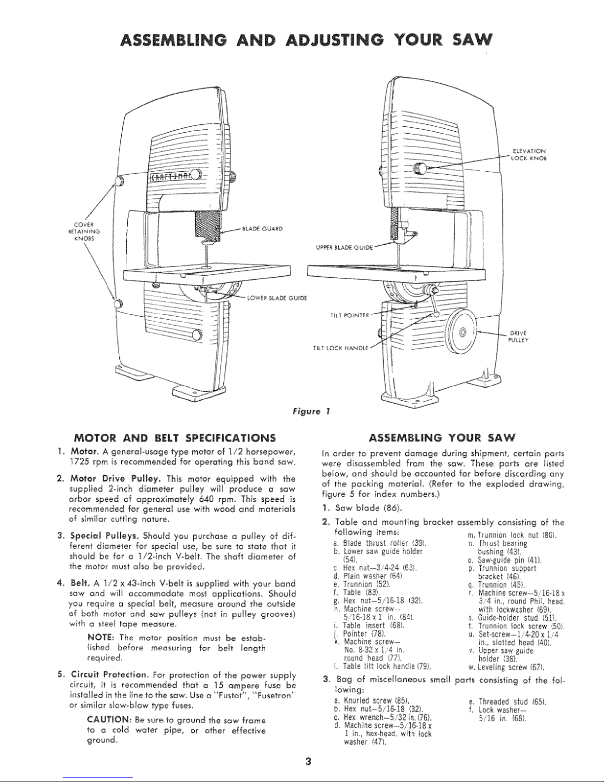
ASSEMBLING AND ADJUSTING YOUR SAW
MOTOR, AND BELT SPECJFiCATi|ONS
] Motor, A generobusoge type motor of }/2 horsepower,
i725 rpm is recommended for operating this bond SOw.
2. Motor DHve PuJJey'_ This motor equipped with the
supp!]ed 2-inch diameter pulley will produce a S_Wi
arbor speed o_ approximately 640 rpm, This speed is
recommended for general use with wood and materials
of simi!ar eutt{ng nature,
3:, Specie| P#i{eys, Should you purchase a pulley of dlf-
ferent diameter for spedat use_.be sure to sto_e that it
shouJd be for a ]/24nch V-belt. The shaft diameter of
the motor must also be provided,
4, Serf, A 1/2 x43dnch V-belt is supplied wlth your band
sow and wi!l accommodate most opplicotions_ Should
you require o special bah, measure around the outside
of both motor and saw puileys (not in policy grooves)
w_th a steel tape measure
NOTE: The motor position must be estab,
tshed before for belt length
5, Circuit £to_ectioa, For proteetioe of the power supply
circuit, it is recommended thorn !5 ampere, fuse be
installed n the iine to the saw Use o "Fustot', 'Tusetran"
or similar slow,-blow _pe fuses
CAUTION: Be sure to ground the saw frame
to a cow water pipe, or other effective
ASSEMBLING YOUR SAW
tn order to prevent damage during shipment, certain RaMs
were disassemb!ed from the saw, These ports o{e listed
below, and shou!d be accounted for before d{scarding any
of the packing material (Refer to the exploded drowlng,
figure 5 for index numbers,}
1_ Sow blade (86),
2 Tobie and mounting bracket assembly consisting of the
following items: m T_unni@_ !0ok n_t 801
3_
a. Blade _h_ust relier {3£) i [hrust bearie£
b. Lewe saw i_ide holle£ busli_g (43).
i54i. 0, Saw=!lida pie (4b,
c Hex 163i. p Trunnion support
d Plain washer (54L b_acka_ 45).
a True_fi0n (52L q Truani0_ I45,
f, Table (83) t. Nachnescrew-5i1618x
I, Rex nut........5/15,18(321, 3/4 in,= re,and Phil head
b Math se sc_e,_,,- wth 10ck,washer {69L
5 1548_1 in (84). re, Guidehelder stlt {Ill
i Table insert i58). L Tru_=eie_ 10okscrew 1%1.
j Partier178) u %t scre_'-......]i4_20_1/4
k Machine screw- i_ slotted he_t t40
No 132xi 4 in v @pet sawl_,,lde
[OU_r_I }_e_d {77L haler 1381
I. Table Iill IICI handle I.?£L _, LeveIinl scre_ (57).
Bag of miscellaneous small pots contesting of tle fol-
a. RoaMed screw (85L
b. tax mst_5/!51S (32L
c No× 'wre_eb=-5/32 i1.(76)
I, lacbi_e SCr'eW--,rb/IY,:I[8 X
i_, hex.head, wth leek
_sber 47),
e. Threaded s_ud (551.
5'15 im (85}.
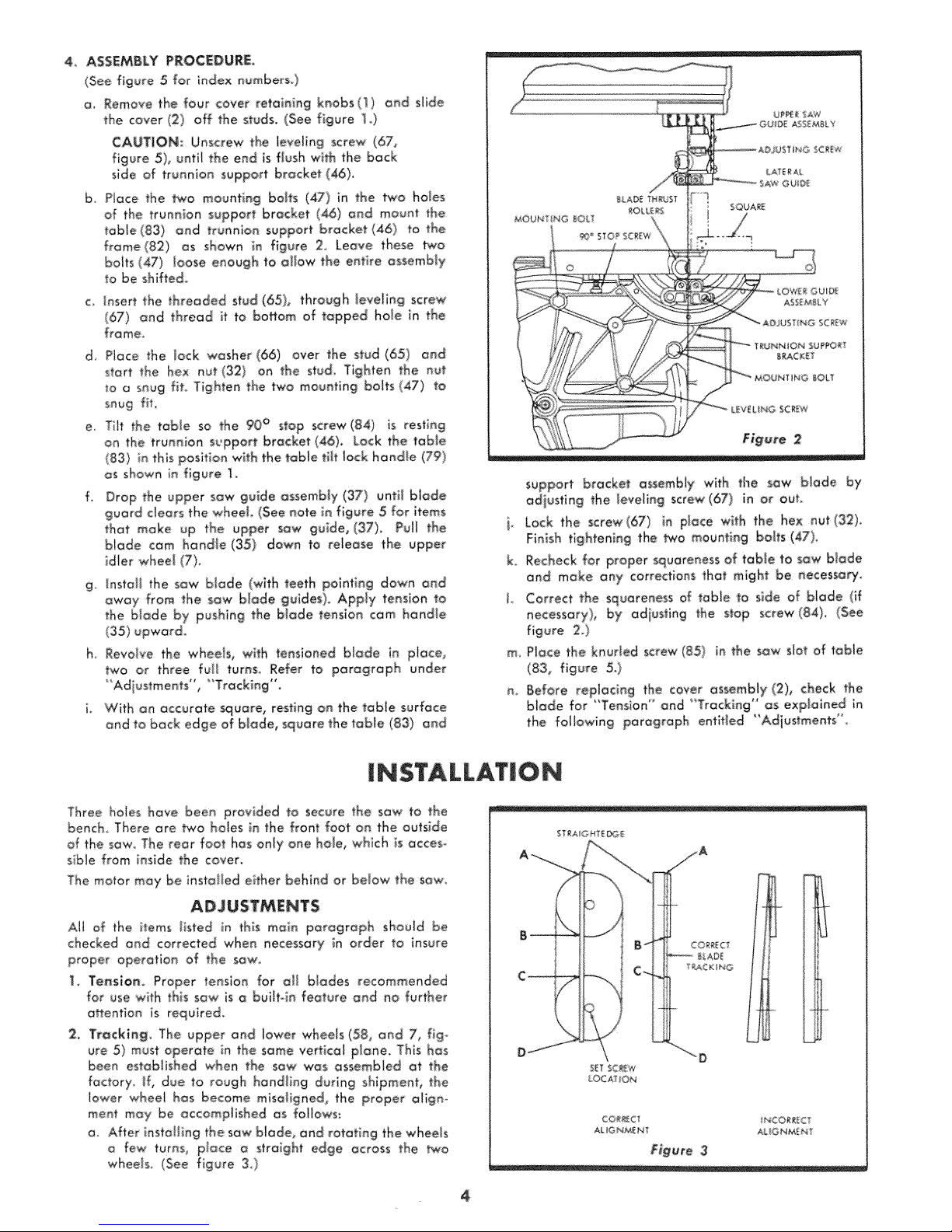
4, ASSEMBLY PROCEDURE.
(See figure 5 for index numbnrsQ
a, Remove 'the four cover retaining knobs (1) and slide
the cover (2) off the studs, (See figure _,,)
CAUTION: Unscrew the leveling screw (67,
figure 5)_ until the end & flesh with the back
slde of trunnion support bracket (46),
b Piece the _o mountieg brits (47) in the two hales
of the trunnion support bracket (_)oed mount the
table(83) end trunnion support bracket (46) to the
f:rome (82) os shown in: figure 2._Leave: these two
bolts (47) _eose enough to allow the eetbe assembly
to be shifted.
c, _nsert the threaded stud (65), through _eve_in,g screw
(67) _nd thread it to bo_om of tapped hole in the
frame,
d, Piece the lock washer (66), over the _tud (651 and
_tort the hex nut (132) on the stud Tighten the nut
u_ a seug fit, Tighten the two meuetieg bobs (47) to
snug fiL
e, Tit the table so the 90° stop screw(84) is resting
on the truen_on support bracket (46), Lock the table
(83) in this position with the tQb_etiff lock handle (79)
as shown in figure ]
f, Drop the upper sow guide assembly (37') until b_ade
guard clears the whoa!, (See note in figure 5 for items
that make up the upper saw guide, (37), Pull the
blade cam handle (35) down to release the upper
_dler wheel (7},
g install the saw blade (with teeth pointing down and
away from the saw blade guides), Apply tension to
the blade by pushing the blade tension cam handl÷
(35) upward_
h, Revalue the whoa!s, with tensioned Made in piece,
two or three fuji turns_ Refer to paragraph under
"Adiustments" , "T_acking '°.
i, With on accurate _uare, resting on the table surface
and to back edge air blade, square the table (83) and
support br'_cke_ assembly with the sow blade by
adjusting the lauding screw (67) in or eu)
i. Lock _he screw(67} in place wlth the h÷× out (32)
Finish tightening the _0 mounting barfs (47),
k. Recheck for propersquareness of table to s_w btade
and make any corrections that might be aeces_Fy
J Correct the squareness af table to side ef blade (if
necessary), by adjus_ieg the stop screw (84), (See
figure 2.}
m_ Place the keurled screw (85_ in the saw slot of tome
(83, figure 5_)
n, Before replacing the cover _ssembJy (2), check the
biade for "Tension" end "TrackMg" as expi_ieed in
the following paragraph entiHed
I $TALLATIO
Three holes have been p_ovided to :secure the saw _o, the
bench There are two holes in the front foot on the ouiside
of the sow The rear foot has only one hole, which is _cces-
sible from inside the cev'er,
The motor may be iest'aI_ed either behind or below the saw
A!l of the i_ems Iisted in this maie paragraph should be
checked and corrected when _ecessary in order to insure
proper operation of the sow,,
1, Te_slom Proper' tensioe for a[[ biades recommended
for use with this sow is o buihoin feature and _0 further
o#eetioe is required,
2, Trecki_g_ The upper and lower wheels (58, end 7, fig°
ure 5) must operate in, the some vertical p!_e, This has
been estob!ished when the sow was assembled _t the
factory, if, due to rough hand_ing during shipment, the
lower wheel has become misoligned, the proper a!igno
meet may be accomplished as fe|iows:
a After installing the sow blade, and rotating the wheels
few turns, place o strolgh_ edge across the two
wheels, (See figure 3)
ST_AiG HTE_E
CORAC iNCORReCT
AIL _G_ME _ t AJ. IG _E N
Figure 3
4
 Loading...