

Craftsman 113.23800 Owner's Manual
Serial
Number
Modelandserial
numbermaybefound
underbeltguard.
Youshouldrecordboth
modelandserialnumber
in asafeplacefor
futureuse.
CAUTION:
Read GENERAL and
ADDITIONAL SAFETY
INSTRUCTIONS
carefully
_ CRRFTSMRN
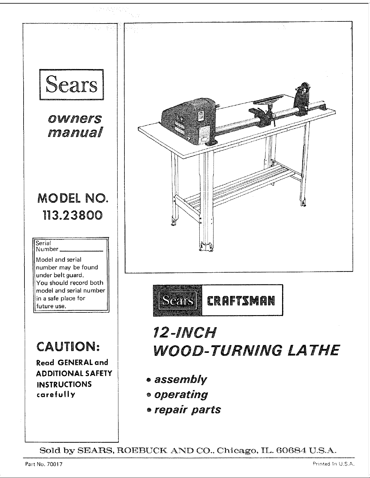
12-iNCH
WOOD-TURNING LA THE
o assembly
®operating
• repair parts
Sold by SEARS, ROEBUCK AND CO., Chicago, IL. 60684 UoS.A.
Part No. 70017 Printed h'_ U.SA.

CRAFTSMAN WOOD TURNING LATHE ]
i
f within one year from the date of purchase, th s Craftsman Wood Turning Lathe fa Is due to a defect in ]
material or workmanship, SearsWill repair it,free of charge,
Warranty service is available by simply contacting the nearest Sears store or Service Center throughout the
United States.
This warranty gives you specific legal rights, an(] you may also have other rights which vary from state to
state.
SEARS, ROEBUCK AND CO.
BSC41-3
SEARS TOWER
CHICAGO, IL, 60684
GENERAL SAFETY INSTRUCTIONS FOR POWER TOOLS
1. KNOW YOUR POWER TOOL
Read the owner's manual careful V. Learn tsapphcatlon
and lim=tations as well as the specifc potential hazards
pecul=ar to this tool.
13. SECURE WORK
use clamp5 or a vise [o _o_o .vof_ wneP, o_actical Jt's
safer than using your nan_q t_ees _om llanos [c ooe_dte
too
2, GROUND ALL TOOLS
This tool is equipped with an approved 3-conductor
cord and a 3-prong grounpm3 type plug to fit the prooer
grounding type receptacle. The green conductor in the
cord is the grounding wire. Never connect tne green wire
to a live terminal.
3. KEEP GUARDS IN PLACE
n worKing oroer, and in proper adj Jstment and align.
ment.
4. REMOVE ADJUSTING KEYS AND WRENCHES
Form habit of checkmg to see mat keys and aejustmg
wrenches are removed from tool before turning it on.
5. KEEP WO RK AREA CLEAN
Cluttered areas and benches =nvlte accidents Floor
must not be shppery due to wax or sawdust.
6. AVOID DANGEROUS ENVIRONMENT
Don t use power tools in damp or wet locations or ex-
pose them to rain. Keep work area well lighted_ Provide
adequate surrounding work sp_ce.
7, KEEP CHILDREN AWAY
All visitors should be kept a safe distance from WOrK area
8. MAKE WORKSHOP KID-PROOF
= Wlttl padlocks, master switches, or bv removing starter
keys.
9. DON'T FORCE TOOL
It wdl do the job better and safer at the rate for which
it was designed
10. USE RIGHT TOOL
Don't force tool or attachment 1o eo a job _t was not
designed for.
11. WEAR PROPER APPAREL
Do not wear loose clothir_J, gloves, neckties or jewelry
(rings, wristwatches) to get caught m moving carts.
NONSLIP footwear is recommended. Wear proteetwe
hair covering to contain long hair Roll long sleeves
above the elbow.
12. USE SAFETY GOGGLES (Head Protection)
14. DON'T OVERREACH
Keepp_oper footing ano balance at a t_mes
15. MAINTAIN TOOLS WITH CARE
Keen tools shard ano c_ean for nest and safest oe_form-
ante. Follow mstructlo[ls for lubricating ano changing
accessories.
16. DISCONNECT TOOLS
before serv;cmg; when changing accessories such as
blades, o_ts. cutters, etc.
17. AVOID ACCIDENTAL STARTING
Make sure switch s 7 "OFF" oosition before mugging
in.
18. USE RECOMMENDED ACCESSORIES
Consult the owner's manure for recommended accessories.
Follow toe nstruct=ons that accomoanv the accessories.
The use of improper accessor=es may cause hazards.
19. NEVER STAND ON TOOL
Serious injury COUlO occur if tne too[ is tipped or if the
cutting tool is accidentally contacted.
Do not store matenals above or near me tOOl such mat
t is necessary to stand on the tool to reach them.
20. CHECK DAMAGED PARTS
Before further use of the tool. a guaro or other cart mat
s damaged should be carefully checked to ensure that it
will ooerate properly and perform _ts ntendep function.
Check for ahgnment of moving parts, Oinolng of moving
parts, breakage of parts, mounting, ano any otner con-
ditions that may affect ts ooerat_on. ,_ guata or other
Dart That _s damageo should be orooerly reoalreG or
replaced
21. DIRECTION OF FEED
Feed work into a blade or cutter against the dl_ection of
rotation of the blade or cutter omv_
22. NEVER LEAVE TOOL RUNNING
UNATTENDED
Turn power off. Don't leave tOOl until !t comes to ._
complete stop.
Wear safety goggles (must comply with ANS Z87.1)
at all times. Also, use face or dust mask if cutting oper
ation is dusty, and ear protectors (plugs or muffs) durin_
extended periods of operation. 2
Safety is a Combination of operator common senseand
alertness at all times when the Lathe is being used.
WARNING: FOR YOUR OWN SAFETY, DO
NOT ATTEMPT TO OPERATE YOUR LATHE
UNTIL IT IS COMPLETELY ASSEMBLED AND
INSTALLED ACCORDING TO THE INSTRUC-
TIONS . .. AND UNTIL YOU HAVE READ
AND UNDERSTAND THE FOLLOWING:
PAGE
1. General Safety Instructions for Power Tools . . 2
2. Getting to Know Your Lathe ............ 13
3. Basic Lathe Operation ................. 15
4. Maintenance ....................... 19
5. The Lathe and motor must be bolted down to a stand
or workbench for stability.
6. Protection: Eyes, Hands, Face, Ears, Body
a, Wear safety gogglesthat comply with ANS Z87.1-
t968, and a face shield if operation is dusty.
Wear ear plugs or muffs during extended periods
of operation.
b, When turning between centers or on the face plate,
always rough-out "out of round" workpieces at
slow speed. Running the Lathe too fast, so that it
vibrates, could cause the workpiece to be thrown
from the Lathe . . . or the turning tool to be
jerked from your hands.
C.
Always revolve the workplace by hand before
turning on the motor, tf the workplece strikes the
tool rest, it could split and be thrown out of the
Lathe.
d. Do not allow the turning tool to "bite" into the
workpiece which could result in splitting of the
workpiece or the workpiece being thrown from
the Lathe. Always position the tool rest above the
centedine of the Lathe for spindle turning, Do not
apply the turning tool to the workpiece below the
level of the tool rest.
e.
Do not run the Lathe in the wrong direction, This
could cause the turning tool to be thrown from
your hands. The Lathe must run in a direction so
that the workpiece turns toward you.
Before attaching a workpiece to the face plate
always "rough it out" to as "true round" as pos-
sible. This will minimize vibration while turning.
Always fasten the workpiece securely to the face
plate,
Failure to perform these set-up operations could
cause the workpiece to be thrown from the Lathe.
g. Avoid awkward hand positions, where a sudden
slip could cause a hand to move into the work-
piece.
7.
8,
9,
10.
11,
h. Remove all loose knots before installing work-
piece between centers or on the face plate.
i. Never leave the Lathe work area with the power
on before the Lathe has come to a complete stop,
or without removing and storing the switch key.
j. Never operate the Lathe with protective cover on
the unused shaft end of the motor removed,
Hang your turning tools on the wall toward the tail-
stock end of the Lathe. Do not lay them on the bench
so that you must reach over the revolving workpiece
to select them,
Keep firm hold and control of the turning tool at all
times. Special caution must be exercised when knots
or voids are exposed to the turning tool.
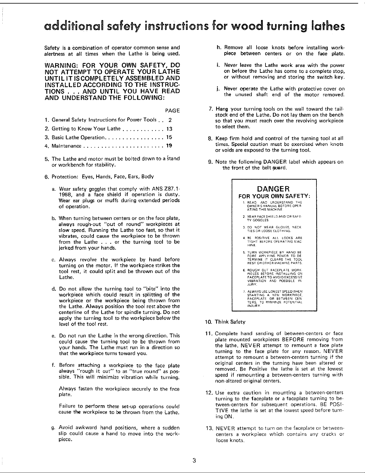
Note the following DANGER label which appears on
the front of the belt _J_rd.
DANGER
FOR YOUR OWN SAFETY:
I REAO AND UNDERSTAND "_HE
OWNER'S ft'ANUAL BEFORE O_ER
ATING THIS MACHINE
2 %15AR FACE SHIELD AND OR SAF E
TY GOGGLES
3 DO NOT WEAR GLOVES NECK
TIES OR LOOSE CLOTHING
4 BE POSIT}VE ALL LOCKS ARE
TIGHT BEFORE OPERATING ,MAC
HINE
5 TURN WORKPIECE BY HAND BE
FORE APPLYING POWER TO DE
TERMINE IT CLEARS THE TOOL
REST OR OTNERMACHIN£ PARTS
6 ROUGH OUT FACEPLATE WORK
PIECES BEFORE INSTALLING ON
FACEPLATETOAVOIDEXCESSIVE
VIBRATION AND POSSIBLE IN
JURY
7 ALWAYSUSE LOWESTSPEEDWHEN
STARTING A NEW WORKPIECE,
FACEPLA_'E OR BETWEEN CEN
TERS. TO M_Ntt2_ZE POTENTIAL
INJURY
Think Safety
Complete hand sending of between-centers or face
plate mounted workpieces BEFORE removing from
the lathe, NEVER attempt to remount a face plate
turning to the face plate for any reason. NEVER
attempt to remount a between-centers turning if the
original centers in the turning have been a{tered or
removed, Be Positive the lathe is set at the lowest
speed if remounting a between-centers turning with
non-altered original centers.
12. Use extra caution in mounting a between-centers
turning to the faceplate or a faceplate turning to be-
tween-centers for subsequent operations. BE POSI-
TIVE the lathe is set at the lowest speed before turn-
ing ON.
13. NEVER attempt to turn on the facep!ate or be._,_een -
centers a workpiece which contains any cracks or
loose knots,
3
• • • •
addlhonai safety mstruchons for wood turning lathes
WARNING: DO NOT ALLOW FAMILIARITY
(GAINED FROM FREQUENT USE OF YOUR
MACHINE) TO BECOME COMMONPLACE.
ALWAYS REMEMBER THAT A CARELESS
FRACTION OF A SECOND IS SUFFICIENT TO
INFLICT SEVER INJURY.
WARNING: THE FOUR STEP LATHE AND
MOTOR PULLEYS FURNISHED ARE DE-
SIGNED TO RUN THE LATHE AT THE COR-
RECT SPEEDS WHEN USED WITH A 1725
R.P.M. MOTOR. DO NOT USE A 3450 R.P.M.
MOTOR TO INCREASE THE SPEED BECAUSE
IT COULD BE DANGEROUS.
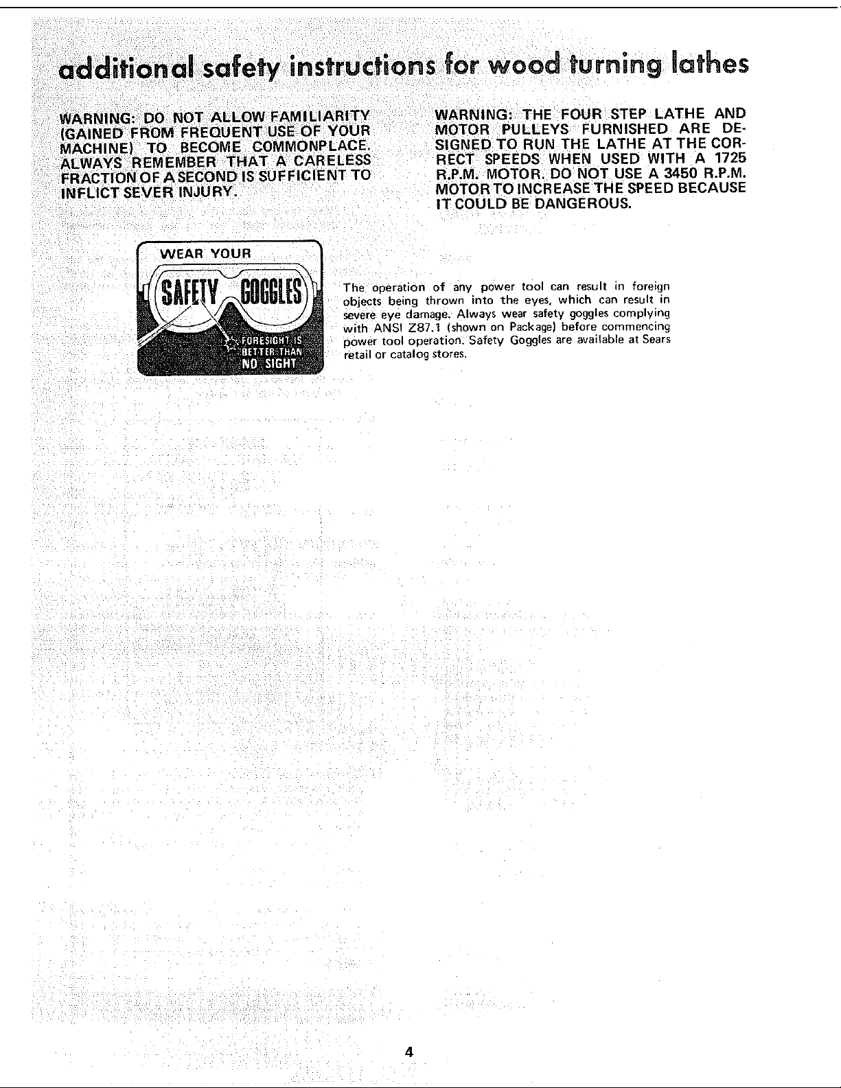
gVEAR YOUR
The operation of anv power tool can result in foreign
objects being thrown into the eves, which can result in
severe eve damage. Always wear safety goggles complying
with ANSI Z87.1 (shown on Package) before commencing
power too_ operation. Safetv Goggles are available at Sears
retail or catalog stores,
4
This Lathe is designed to use a 1725 RPM motor only. Do
not use any motor that runs faster than 1725 RPM, It is
wired for operation on 110-120 volts, 60 Hz., alternating
current. IT MUST NOT BE CONVERTED TO OPERATE
ON 230 VOLTS. EVEN THOUGH SOME OF THE RE-
COMMENDED MOTORSARE DUAL VOLTAGE.
THESE MOTORS HAVE BEEN FOUND TO RE
ACCEPTABLE FOR USE ON THIS TOOL,
HP RPM VOLTS CATALOG NO.
1/3 1725 110-120 1250
1/2 1725 110-120 1254
1/2 1725 110-120 1255
CAUTION: Do not use blower or washing machine motors
or any motor with an automatic reset overload protector
as their use may be hazardous.
CONNECTING TO POWER SOURCE OUTLET
This machine must be grounded while in use to protect
the operator from electric shock.
Plug power cord into a 110-120V properly grounded type
outlet protected by a 15-amp. time delay or Circuit-Saver
fuse or circuit breaker.
If VOU are not usre that your outlet is properly grounded,
have it check by a qualified electrician.
WARNING: DO NOT PERMIT FINGERSTO TOUCH THE
TERMINALS OF PLUGS WHEN INSTALLING OR RE-
MOVING THE PLUG TO OR FROM THE OUTLET.
WARNING: IF NOT PROPERLY GROUNDED THIS
POWER TOOL CAN INCUR THE POTENTIAL HAZARD
OF ELECTRICAL SHOCK. PARTICULARLY WHEN USED
IN DAMP LOCATIONS IN PROXIMITY TO PLUMBING.
IF AN ELECTRICAL SHOCK OCCURS THERE IS THE
POTENTIAL OF A SECONDARY HAZARD SUCH AS
YOUR HANDS CONTACTING THE CUTTING TOOL.
If power cord is worn or cut, or damaged in any way, have
it replaced immediately.
If your unit is for use on less than 150 volts it has a plug
that looks like below.
PROPERLY J
GROUNDED I
OUTLET.,,,,...!
/n ui
\ /
/_ UJ I
3--PRONG
PLUG
GROUNDING
PRONG
This power tool is equipped with a 3*conductor cord and
grounding type plug which has a grounding prong, approved
by Underwriters' Laboratories and the Canadian*Standards
Association. "Tile ground conductor has a green jacket and
is attached to the tool housing at one end and to the ground
prong in the _ttachment plug at the other end.
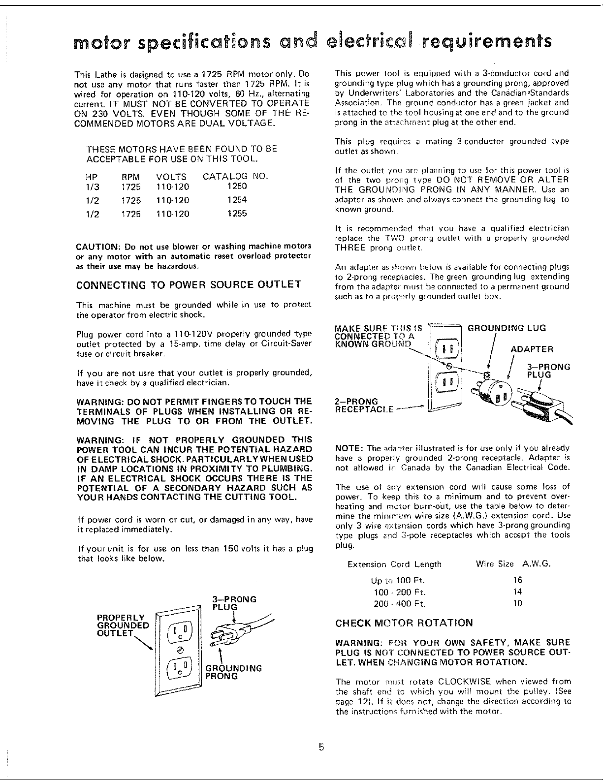
This plug requires a mating 3-conductor grounded type
outlet as shown.
If the outlet you are planning to use for this power tool is
of the two prong b/pe DO NOT REMOVE OR ALTER
THE GROUNDING PRONG IN ANY MANNER. Use an
adapter as shown and always connect the grounding lug to
known ground.
It is recommended that you have a qualified electrician
replace the TWO ploI_g outlet with a proper!y grounded
THREE pro_g o,_iet,
An adapter as shown below is available for connecting plugs
to 2-prong receptacles. The green grounding lug extending
from the adapter must be connected to a permanent ground
such as to a properly grounded outlet box.
MAKE SURE "flits tS
CONNECTED TO A I
KNOWNGROlJ_!_ ii/',,
2-PRONG
RECEPTACLE .........."-_
GROUNDING LUG
ADAPTER
NOTE: The ada!._ter illustrated is for use only if you already
have a properly grounded 2-prong receptacle. Adapter is
not allowed ir_ Canada by the Canadian Electrical Code.
The use of any extension cord will cause some loss of
power. To keep this to a minimum and to prevent over-
heating and motor burn-out, use the table below to deter-
mine the minimum wire size (A.W.G,) extension cord. Use
only 3 wire extet/sion cords which have 3-prong grounding
type plugs aqd 3-pole receptacles which accept the tools
plug.
Extension Cord Length Wire Size A.W.G.
Upto 100 Ft. 16
100-200 Ft. 14
200-400 Ft, 10
CHECK MOTOR ROTATION
WARNING: FOR YOUR OWN SAFETY, MAKE SURE
PLUG IS NOT CONNECTED TO POWER SOURCE OUT-
LET. WHEN CHANGING MOTOR ROTATION.
The motor must rotate CLOCKWISE when viewed from
the shaft enC o which you wilt mount the pulley. (See
page 12}. If b does not, change the direction according to
the instructions furnished with the motor.
5
ontents
Check motor rotation ................ 12
GETTING TO KNOW YOUR WOOD LATHE ......... 13
Belt guard lock .................................. 13
Index pin ..................................... 13
Spindle lock hole ................ 13
Tool rest lock .." .................,., . ............ 13
Tool rest base lock ............................... 13
Handwheel ..................................... 13
Tailstock ram lock ............................... 13
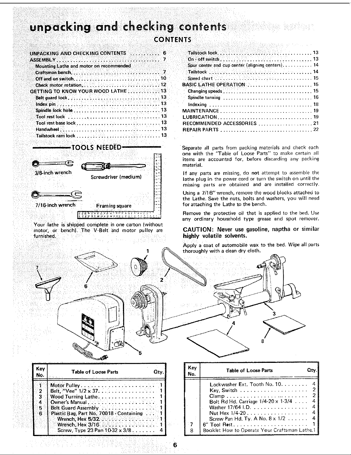
TOOLS NEEDED ='-'=`-'=.'."'.".'-
3/8-inch wrench
Screwdriver (medium)
7/16-inch wrench Framing square
Your lethe is shipped complete in one carton [without
motor, or bench). The V-Belt and motor pulley are
"furnished.
................... 13
On - off switch .................................. 13
Spur center and cup center (aligning centers) ........... 14
Tailstock .................................... 14
Speed chart .................................... 15
BASIC LATHE OPERATIOIk ........................ 15
Changing speeds ................................. 15
Spindle turning ............................... 16
Indexing ...................................... 18
MAINTENANCE ................................. 19
LUBRICATIOI_ ................................... 19
RECOMMENDED ACCESSORIES .................... 21
REPAIR PARTS .................................. 22
Separate all parts from packing materials and check each
one with the "Table ol Loose Parts" to make certain all
_tems are accounted for, before discarding any packin£
material,
If any parts are missing, ao not attempt to assemDle th_
lathe plug in zne power cord or turn the switcn on until tn(
mtssing oarta are obtained and are nstalled correctly
Using a 7 16" wrench, remove the wood blocks attached to
the Lathe. Save the nuts. bolts and washers, you will need
for attaching the Lathe to the bench.
Remove the protective oil that is applied to the bed. Usa
any ordinary household type grease anc spot remover,
CAUTION: Never use gasoline, naptha or similar
highly volatile solvents,
Apply a coat of automobile wax to the bed. Wipe all parts
thoroughly with a clean dry cloth.
Key Table of Loose Parts Qty.
No.
Motor Pulley ...................... 1
Belt, 'Vee 1/2x37 ................. 1 !
3 Wood Turning Lathe ................. 1
4 1Owner a Manual ....................
5 Belt Guard Assembly ................ 1
6 PlasticBag, Part No. 70018-Containing ... 1
Wrench, Hex 5/32. ................ 1Wrench, He× 3/16 ................ 1
Screw, Type 23 Pan 10-32 x 3/8 ....... 4
3
Key Table of Loose Parts Qty,
No.
7
8
Lockwasher Ext. Tooth No. 10 ........ 4
Key, Switch .................... 2
Clamp ......................... 2
Bolt Rd Hd. Carriage 1/4-20 x 1-3/4 .... 4
Washer 17/64 LD ................. 4
Nut Hex 1/4-20 .................. 4
Screw Pan Hd. Ty. A No. 8 x 1/2 ...... 4
6" Tool Rest ...................... 1
Booklet How to Operate Yeur Craftsman Lathe, 1
6
assembly
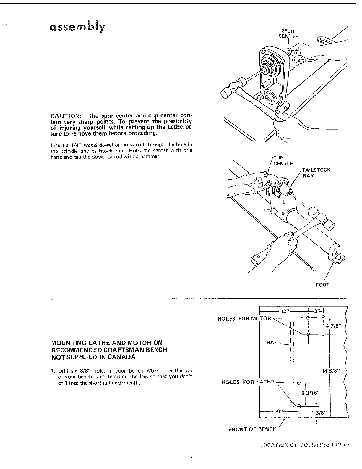
CAUTION: The spur center and cup center con-
tain very sharp points. To prevent the possibility
of injuring yourself while setting up the Lathe, be
sure to remove them before proceding.
Insert a 1/4" wood dowel or brass rod through the hole in
the spindle and tailstock ram. Hold the center with one
hand and tap the dowel or rod with a hammer.
,CUP
MTER
TAILSTOCK
FOOT
MOUNTING LATHE AND MOTOR ON
RECOMMENDED CRAFTSMAN BENCH
NOT SUPPLIED IN CANADA
1. Drill six 3/8" holes in your bench. Make sure the top
of vour bench is centered on the tegsso that you don't
drill into the short rail underneath,
J
14 5/8"
HOLES FOR LATHE\ ,I"_----_
\I , [6,3/16
t
LOCA'I'ION 0;* #_OUFFfU'_G HC_L_;.S
assembly
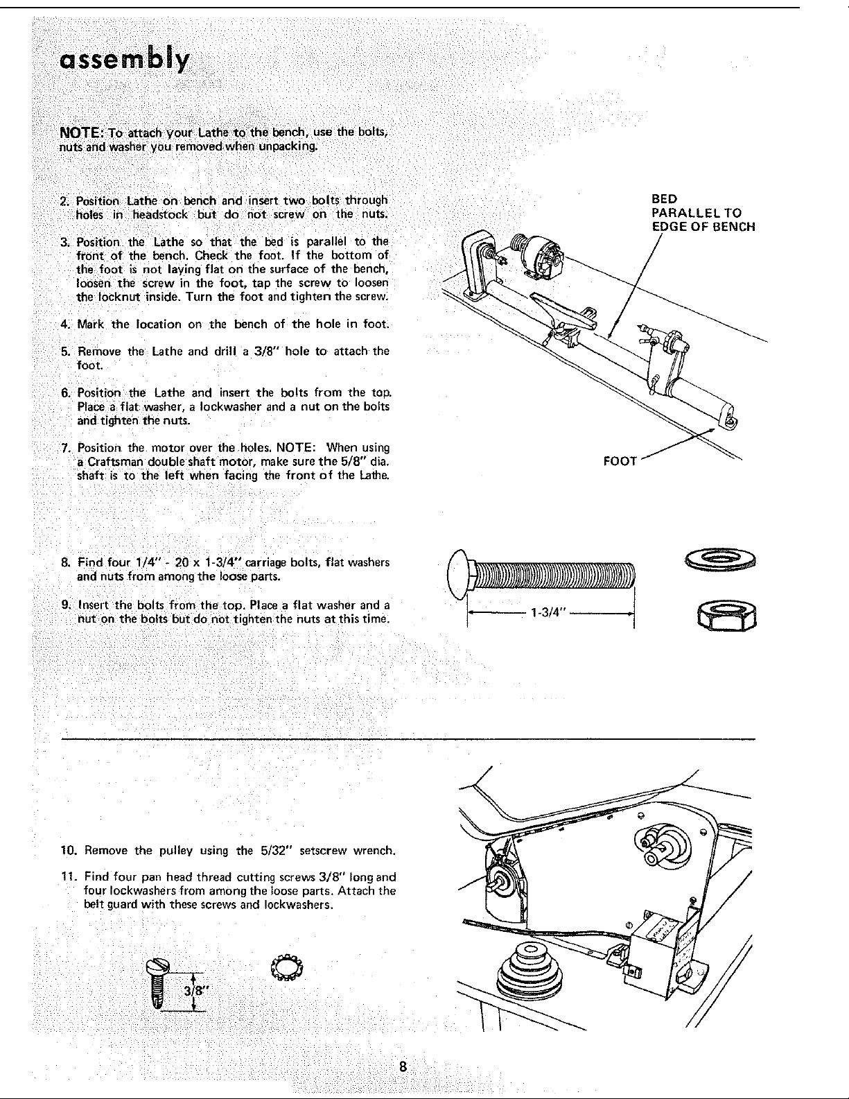
NOTE: To attach your Lathe to the bench, use the bolts,
nuts and washer you removed when unpacking.
2. Position Lathe on bench and nsert two bolts through
holes in headstock but do not screw on the nuts.
3. Position the Lathe so that the bed is parallel to the
front of the bench. Check the foot. If the bottom of
the foot is not laying flat on the surface of the bench,
loosen the screw in the foot, tap the screw to loosen
the Iocknut inside. Turn the foot and tighten the screw.
4. Mark the location on the bench of the hole in foot,
5. Remove the Lathe and drill a 3/8" hole to attach the
foot.
6. Position the Lathe and insert the bolts from the toP.
Placea flat washer, a Iockwasher and a nut on the bolts
and tighten the nuts.
7. Position the motor over the holes. NOTE: When using
a Craftsman double shaft motor, make sure the 5/8" dia.
shaft is to the left when facing the front of the Lath_
FOOl
BED
PARALLELTO
EDGE OF BENCH
/
8. Find four 1/4" - 20 x 1-3/4"' carriagebolts, flat washers
and nuts from amongthe loose pans.
9. Insert the bolts from the top. Place a flat washer and a
nut on the bolts but do not tighten the nuts at this time,
10. Remove the pulley using the 5/32" setscrew wrench.
11. Find four pan head thread cutting screws 3/8" long and
four Iockwashers from among the loose parts, Attach the
belt guard with these screws and Iockwashers.
©
B"
/
 Loading...