

Page 1
Save This №nuai
For Future Reference
owners
manual
MODEL NO.
113.225900
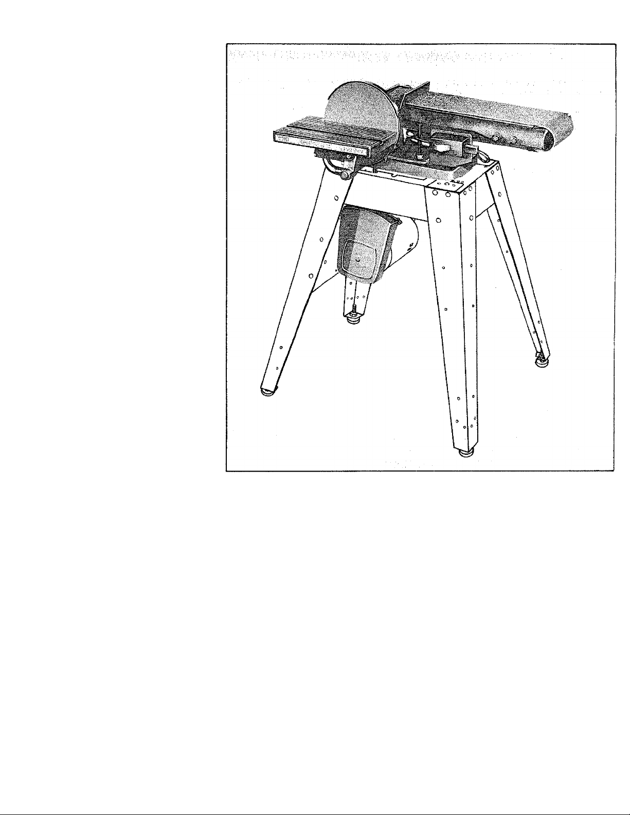
BELT AND DISC
SANDER ONLY
MODEL NO.
113.225931
BELT AND DISC
SANDER/WITH
LEGS AND MOTOR
Serial
Number
Model and serial
number may be found
at the right-hand side
of the base.
You should record both
model and serial number
in a safe place for
future use.
CAUTION
Read SAFETY
INSTRUCTIONS
carefully
CRRFTSMRN
BELT AND DISC SANDER
• assembly
® operating
® repair parts
Sold by SEARS, ROEBUCK AND CO., Chicago, IL. 60684 U.S.A.
Part No. 68073 Printed m U.S.A,
Page 2

FULL ONE YEAR WARRANTY ON CRAFTSMAN BELT AND DISC SANDER
If within drie year from the date of purchase^ this Craftsman Belt and Disc Sander fails due to a defect in
material or workmanship. Sears will repair it, free of qharge.^ ^ ^ ^
WARRANTY SERVICE IS AVAILABLE BY SIMPLY CONTACTING THE NEAREST SEARS STORE
OR SERVICE CENTER THROUGHOUT THE UNITED STATES. ; ^ ^
This warrarrty gives you specific legal rights, and you may also have other rights which vary from state to
state,
SEARS, ROEBUCK AND CO., Dept. 698/731A, Sears Tower, Chicago, IL 60684
gehéral safe instructions for power fools
1. KNOW YOUR PÓWER TOOL ^ ^ ^
Read and : understand the owner's manual and labels
affixed to thè tool. Learn its application and limitations as
' well as the specific potential hazards peculiar tp this tòoi:-
2 GROUND ALL TOOLS
^ with an approved 3 conductor
grounding type plug to fit the proper
grounding type receptacle. The gieen conductor in the
cord is the.Vgrourrding Wire, Never connect the green wire
to a live terminal. ■
3. KEEP GUARDS IN PLACE
■ tn; vvóric íng. order, and rn proper adjustment and align
4 REMOVE ADJUSTING KEYS AND WRENCHES
^ Trsrm : habit : of checkirig. to see that keys and adjusting
vvrenches are-rernoveri trorn tool,before turning .it on.
5. KEEP WORK AREA CLEAN
. Cluttered, áréés and benches: invite accidents. Floor
must not be slippery due to wax or sawdust.
6. AVOID DANGEROUS ENVIRONMENT
Don't use power tools n damps or wet locations ot ex .
;i'v,e them to tarn. Keep work aica well lighter!. Provide
. : ;a<iepu3te surrounding work space : ;r .;
7. KEEP CHILDREN AWAY
Ali visitors 5hóü(d}be:kepti-d:sated'staricellrdm.jWork area,,
8. MAKE WORKSHOP CHILD-PROOF
With pacifocks. masi(?i swilcfies, or t>y: rerriovinq starter
keys . • . ■ ■ '■ ■: ' • • ■. ■" •
9. DON'T FORCE TOOL
:: " it will do. the. job.:better and safer at the rate for Which .
it was designed : .. : .
10. USE RIGHT TOOL
Don't foice tool oi attachment to do a job. it was not
ciesigned for, ...
It. WEAR PROPER APPAREL
Do not wear loose clothing, gltsves, neckties or jewelry
(rings, wristwatches) to get caught .in moving, parts, j
NONSLIP footwear is recommended. Wear protective,
hair covering to contain Song hair.. Roil long sleeves
above the elbow.
12. USE SAFETY GOGGLES (Head Protection)
Wear safety goggles (must cotrtply with ANSI Z87.Ì) at all
times; Everyday eyeglasses only have impact resistant
lenses, they are NOT safety glasses. Also, use face or dust
mask if cutting operation is dusty, and ear protectors
(plugs or muffs) during extended periods of operation.
13. SECURE WORK
Use clamps or a vise to hold work when practical. It's
safer than using your hand, frees both hands to operate
: tool.
14. DON'T OVERREACH
Keep proper footing and balance at all times.
15 MAINTAIN TOOLS WITH CARE
Keep tools sharp and clean for best and safest perform
ance. Follow instructions for lubricating and changing
accessories.
16. DISGONNECT TOOLS
before servicing, when changing accessories such as
blades, bits, cutters, etc.
17. AVOID ACCIDENTAL STARTING
Make sure switch is |n "OFF" position before plugging
in.
18. USE RECOMMENDED ACCESSORIES
: ; Cohsull the owner's manual for recommended accessories.
Follow the instructions that accompany the accessories.
" The use of improper accessories may cause hazards.
19. NEVER STAND ON TOOL
injury could occur if the too! is tipped or if the
cutting tool IS accidentally contacted.
Do not store materials above or near the tool such that
: It IS necessary to stand on the tool to reach them.
20. CHECK DAMAGED PARTS
Before further use of the tool, a guard or other part that
IS damaged should be carefully checked to ensure that it
will operate property and perform rts intended function.
Check for alignment of moving parts, binding of moving
parts, breakage of parts, mounting, and any other conditioiis that may affect ns operation. A guard or other
part that IS damaged should be properly repaired or
replaced. .
21. DIRECTION OF FEED
Feed work into a blade or cutter against the direction of
rotation of the blade or cutter only.
22 NEVER LEAVE TOOL RUNNING
UNATTENDED
Turn power off. Don't leave tool until it comes to a
complete stop
Page 3

sofety insfryctlohs f©r belt oiid: di^c soiicler
Safetyis a cprntJination of common sense, staying alert and
knowing how your belt and disc sander works. Read this
manual to understand this sander.
BEFORE USING THE SANDER:
WARNING: To avoid mistakes that could cause serious, per
manent injury, do not plug the sander in until the following
steps are completed.
• Assembly, (See pages 7-16.)
® Learn the use and function of the ON-OFF swilch,
backstop lock screw, belt adjusting screws, belt lock
ing screws, work table and work table tilt lock screw.
(See pages 16-18.)
• Review and understanding of ail safety instructions and
operating procedures in this manual.
• Review of the maintenance methods for this sander.
(See page 22.)
Read the following DANGER label found on the front of the
sander:
fl A R BEfORE OPERATiNO MAC«'Ni
FOB YOUR 3 lAAINlAIK ''16 uvCr'WAKlWUMCI.EAeANCE
OWN SAF£TY stit un
1 HtAO AND UNOEHSTAND OWNiaS
^ 2 WEAR SAFgty iiOddLeS ASP SU5T MASH
i AVO'O-ArCKBACH'fWORKPlECt THUCrWEi
AI VOLJI - DO NOT USE RIGHT HAt.r OT’ DISC
S ACWATSSuPPOftT WOn><.P^EG5 WITH 'iiAC.«!-
STpl- Oft -vVOfiXr45ig •
S N SHOF'VAC’OD'SC
M0US:>«G WM5N 5ANDIKQ iftOH OR STEEL l»
WHEN INSTALLING OR MOVING THE SANDER.
AVOID DANGEROUS ENVIRONMENT. Use the sander in a
dry, indoor place protected from rain. Keep work area weii
lighted.
Place the sander so neither the user or bystanders are forced
to stand in line with the abrasive belt or disc.
To avoid injury from unexpected sander movement:
• Put the sander on a firm level surface where there is
plenty of room for handling and properly supporting the
workpiece.
» Support the sander so it does not rock.
» Bolt the sander to the floor or work surface if it tends
to slip, walk, or slide during normal use.
To avoid injury or death from electrical shock;
» GROUND THE SANDER. This sander has an approved
3-conductor cord and a 3-prong grounding type plug.
Use only 3-wire, grounded outlets rated 120 volts, 15
amperes (amps). The green conductor in the cord is the
grounding wire. To avoid eiectrociitioh, NEVER connect
the green wire to a live terminal.
• Make sure your fingers do not touch the plug's metai
prongs when plugging or unplugging the sander.
To avoid back injury, get help or use recommended casters
when you need to move the sander. Always get help if you
need to lift the sander.
NEVER STAND ON TOOL. Serious injury could occur if the
tool tips or you accidentally hit the cutting tool. Do not store
anything above or near the tool where anyone might stand
on the tool to reach them.
..........................
BEFORE EACH USE:
inspect your sander.
DISCONNECT THE SANDER. Toavoid injury from accidental
starting, unplug the sander, turn the switch off and remove
the switch key before changing the setup, sanding disc or
belt or adjusting anything.
CHECK DAMAGED PARTS. Check for:
« alignment of moving parts,
o binding of moving parts.
® broken parts,
* stable mounting, and
e any other conditions that may affect the way the sander
works.
WARNING; The 2-1/2" machine pulley and the 2" motor
pulley furnished will run the disc at about 2700 RPWI and the
belt at about 2100 FPW! (Feet Per Minute) when used with a
3450 RPM motor. To avoid throwing of work or broken
sander fragments, never substitute or interchange these
pulleys to increase this speed.
If any part is missing, bent, or broken in any way, or any elec
trical parts don't work properly, turn the sander off and
unplug the sander. REPLACE damaged, missing, or failed
parts before using the sander again. .
MAINTAIN TOOLS WITH CARE. Keep the sander clean for
best and safest performance. Follow instructions for lubri
cating.
REMOVE ADJUSTING KEYS AND WRENCHES from tool
before turning it on.
To avoid injury from jams, slips or thrown pieces:
• USE ONLY RECOMMENDED ACCESSORIES, (See
page 22.) Consult this Owner's manual for recom
mended accessories. Follow the instructions that
come with the accessories. The use of improper ac
cessories may cause risk of injury to persons.
* Adjust table to clear the sanding surface by no more
than 1/16 of an inch.
■ Make sure all clamps and locks are tight and no parts
have excessive play.
• KEEPWORK AREA CLEAN, Cluttered areas and benches
invite accidents. Floor must not be slippery.
To avoid burns or other fire damage, never use the sander
near flammable liquids, vapors or gases.
Plan ahead to protect your eyes, hands, face, ears.
KNOW YOUR SANDER. Read and understand the owner's
manual and labels affixed to the tool. Learn its application
and limitations as well as the specific potential hazards pecu
liar to this tool.
To avoid injury from accidental contact with moving parts,
don't do layout, assembly, or setup work on the sander while
any parts are moving,
AVOID ACCIDENTAL STARTING, Make sure switch is "OFF"
before plugging sander into a power outlet.
Page 4

solely instructions for belt ond disc sctnder
Plan your work.
USETHERIGHTTOOU. Don't force toot or attachment to doa
job it was not designed to do. :
CAUTION: This machine is notdesigned for heavy deburring
operations. When finishing metals, sparks or hot fragments
could cause a fire. To avoid this, disconnect any dust col
lecting hose from the sander. Also, remove al! traces of wood
diist from inside dust traps in the Sander.
Dress for safety.
s- This
cán cause permanent eye damage. Wear safety goggles {not
gláséés) that cbrnpl^^ Z87.1. Everyday eyeglasses
have only itripact resistant lenses. They are not safety glasses.
Safety goggles are available at Sears retail cataiog stores.
Glasses or goggles not in compliance with ANSÍ Z87.1 could
seriously hurl you when they break. ^
* Do not wear loose clothing, gloves, neckties or jewelry
(rings, wrist watches}, they can get caught and draw
you into moving parts.
* Wear nonslip footwear, /
.■ Tie backfong hair, . : ■ .
; • Roll long sleeves above the elbow. ;
* Noise levéis vary widely To a void possible hearing dant-
® Sanding operatioris áre usually dusty. Wear a dust mask
along with the safety goggles. . ^ .
inspect your workpiece,
Make sure there are ríoháils or foreign objects ih the part of
the workpiece to be sanded. ■
Plan your work to avoid THRÓWÉACKS—when the work
piece catches on the sanding belt or disc and is torn from
your hands. ■ ■ '.- V, ; ■ ■ -
• Make sure there's no debris between the workpiece and
its supports. . ■ V .
• When sanding irregularly shaped workpieces, plan your
work support so it witi not slip and be pulled from your
hands.
• Use extra caution with large, very small or awkward
. pieces: • : . . .
« Never use this tool to finish pieces too small to hold by
hand. : ^ .
• Use extra supports (tables, saw horses, blocks, etc.) for
: any workpieces large enough to tip when not held down
to the table top. ,
• NEVER use another person as a substitute for a table
extension, or as additional support for a workpiece that
is longer or wider than the basic sander table, or to help
feed, support or pull the workpiece,
• When finishing onthe Disc, always press the wbrkpiece
against the "Down" side of the disc. Sanding against the
side coming up from under the table could damage the
work by making it "chatter," or tear the work from your
hands and throw it.
• Sand only one workpiece at a time.
• Clear everything except the workpiece and related sup
port devices off the table before turning the sander on.
Plan the way you will hold the workpiece from start to finish.
Avoid awkward operations and hand positions where a sud
den slip could cause fingers or hand to move into a sanding
surface. Keep fingers away from where the belt goes into the
dust trap.
DON'T OVERREACH, Keep good footing and balance.
Keep your face and body to one side, out of line with a pos
sible throwback.
WHENEVER SANDER IS RUNNING.
WARNING: Don't let familiarity (gained from frequent use of
your belt and disc sander) cause a careless mistake. A care
less fraction of a second is enough to cause a severe injury.
Before starting your cut, watch the sander while it runs. If it
makes an unfamiliar noise or vibrates a lot, stop immediately.
Turn the sander off. Unplug the sander. Do not restart until
finding and correcting the problem.
Make sure the sanding disc turns counterclockwise before
using the sander.
KEEPC HIED REN AWAY. Keepallvisitorsasafedistancefrom
the sander. Make sure bystanders are clearof the sander and
vvprkpiece. :
DON'T FORCE TOOL. It will do the job better and safer at its
designated rate. Press the workpiece against the sanding
rriaterial only hard enough to let it sand without bogging
down or binding.
Before freeing any jammed material:
: «Turn switch "OFF."
; • Unplug the sander.
• Wait for ail moving parts to stop.
To avoid throwback of the workpiece, use workpiece supports
for all flat surface sanding.
BEFORE LEAVING THE SANDER:
Wait for al! moving parts to stop.
Make workshop child-proof. Lock the shop. Disconnect
rhaster svvitches. Remove the yellow switch key Store it
avVay frorn children and others not qualified to use the tool.
Page 5
electrical requiremerits
CONNECTING TO POWER SOURCE OUTLET
This machine must be grounded white in use to protect
the ofjerator from electric shock.
Plug power cord into a 120V properly grounded type outlet
protected by a 15-amp. dual element time delay or CircuitSaver fuse or circuit breaker.
If you are not sure that your outlet is properly grounded,
have it checked by a qualified electrician.
WARNING: DO NOT PERMIT FINGERS TO TOUCH THE
TERMINALS OF PLUGS WHEN INSTALLING OR RE
MOVING THE PLUG TO OR FROM THE OUTLET.
WARNING: IF NOT PROPERLY GROUNDED THIS
POWER TOOL CAN INCUR THE POTENTIAL HAZARD
OF ELECTRICAL SHOCK. PARTICULARLY WHEN USED
IN DAMP LOCATIONS IN PROXIMITY TO PLUMBING.
IF AN ELECTRICAL SHOCK OCCURS THERE IS THE
POTENTIAL OF A SECONDARY HAZARD SUCH AS
YOUR HANDS CONTACTING THE ABRASIVE BELT
OR DISC.
If power cord is worn or cut, or damaged in any way, have
it replaced immediately.
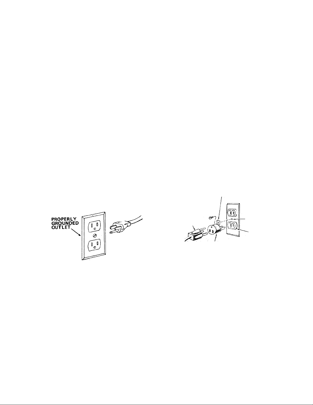
Your unit is wired for 120 volts and has a plug that looks like
the one shown below.
If the outlet you are planning to use for this power tool is
of the two prong type DO NOT REMOVE OR ALTER
THE GROUNDING PRONG IN ANY MANNER, Use an
adapter as shown and always connect the grounding lug to
known ground.
It is recommended that you have a qualified electrician
replace the TWO prong outlet with a properly grounded
THREE prong outlet,
A temporary adapter as shown below is available for
connecting plugs to 2-prong receptacles. The green ground
ing lug extending from the adapter must be connected to a
permanent ground such as to a properly grounded outlet
box.
Atemporary adapter asillustrated is available for connecting
plugs to 2-prong receptacles. The temporary adapter should
be used only until a properly grounded outlet can be
installed by a qualified electrician.
NOTE: The adapter illustrated is for use only if you already
have a properly grounded 2-prong receptacle.
The use of any extension cord will cause some loss of
power. To keep this to a minimum and to prevent over
heating and motor burn-out, use the table below to deter
mine the minimum wire size (A.W.G.) extension cord. Use
only 3 wire extension cords which have 3-prong grounding
type plugs and 3-poie receptacles which accept the tools
plug.
GROUNDING LUG
3-PRONG
PLUG
I
GROUNDING
PRONG
This power tool is equipped with a 3-conductor cord and
grounding type plug, approved by Underwriters' Labora
tories and the Canadian Standards Association. The ground
conductor has a green jacket and is attached to the tool hous
ing at one end and totheground prong inthe attachment plug
at the other end.
This plug requires a mating 3-conducior grounded type out
let as shown.
3-PRONG
PLUG
ADAPTER
Extension Cord Length Wire Size A.W.G.
0-25 Ft
...........................................
26-50Ft
...............................................
51-100Ft.............................................12
MAKE SURE THIS IS
CONNECTED TO A
KNOWN GROUND
2-PRONG
RECEPTACLE
- 16
14
CHECK MOTOR ROTATION
Place the motor on your workbench or on the floor.
Standing clear of the motor shaft, plug the motor cord into a
properly grounded outlet. Notice the rotation of the shaft.
As you look directly at the motor shaft it should be turning in
the counterclockwise direction Ss v . If the motor shaft is
turning counterclockwise, remove the plug from the power
outlet and continue the assembly procedures. If the motor is
turning clockwise, remove the plug from the power outlet
and contact your Sears Store immediately.
Page 6
CONTENTS
safety INSTRUCTIONS FOR POWER TOOLS 2
ADDITIONAL SAFETY INSTRUCTIONS FOR BELT AND
Belt Locking Screws..................................................17
Work Table Tilt Lock Screw
Backstop Lock Screw
ELECTRICAL REQUIREMENTS
.........................
.::,,.............5
Belt Table Locking Boils
Belt Table Stop......................................................... 18
UNPACKING AND dNECKlNG CONTENTS6
ASSEMBLY ...........,:.,.....„.„.,7
: : ; ; Assembling Steel: Legs..:.;...,..,,8
Mounting Belt and Disc Sander on Steel Leg Set...... 8
: installing Sanding Disc and Dust Trap .
....
9
Installing Motor, V-BeitTensioning and Tracking .... 11
Óri-Otf Switch.:.:.,.,............................................... 12
Installing Work Table ...14
installing Abrasive Beit Tensioning and Tracking ....14
Installing Belt Dust Trap.........
.........................
........15
Installing Backstop 16
GETTING TO KNOW YOUR SANDER
........................
16
Belt Adjusting Screws ..,.,.„,...,.17
BASIC OPERATION ..
: Surface Finishing on the Abrasive Belt
: End Finishing on the Abrasive Belt
Finishing Curved Edges on the Abrasive Belt
Finishing Small End Surfaces and Curved Edges
MAINTENANCE
Motor Maintenance and Lubrication........................22
LUBRICATION...................................................................... 22
Recomnnended Accessories
TROUBLESHOOTING
REPAIR PARTS
Motor Connections....................................................29
У op a c kiln g checking contents
Model ; 11^ and Disc Sander is shipped
eoniplete in one carton but DOES NOT INCLUDE Steel
Legs or Motor. :
Model 113.225931 Belt and Disc Sander is shipped
complete in one carton and INCLUDES Steel Legs and
Motor.
Separate all parts from packing materials and check each
; : item with iliustration and;'Table of Loose Parts." Make
certain all iterns are 'accounted for, before discarding any
packing material. ^ ^ ^
If any parts are missing, do not attempt to assemble the
Beit and Disc Sander, plug in the power cord, or turn the
. svvitch on Liritil, the missing parts: are . obtained and
■ ; installed correctly. , : ■ ■
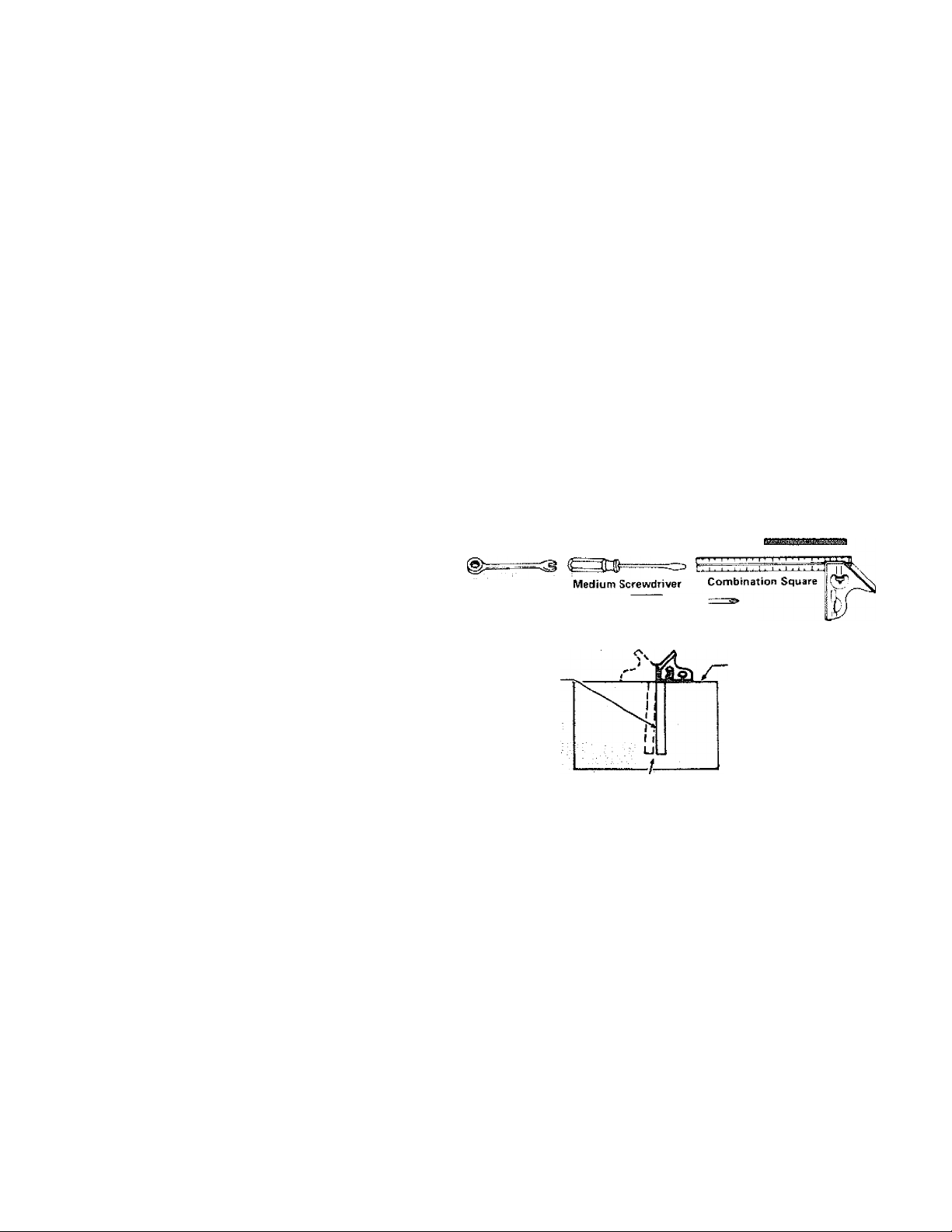
Using a 1/2" wrench; remove the plywood attached to
the machine. Save; the nuts and bolts and washers; You
wit! need them for attaching the machine to the base.
1/2" Wrench
7/16" Wrench
3/4" Wrench
3/8" Wrench
DRAW light
LINE 014 ВОДНО
ALONG THIS EDGE
.........
............................
.....
..........i...............................
...........................................18
..........................................................
...................
.........................
.......
21
on Disc...................................................................21
....................................................................
...................................
..........................................................
...................................................................25
TOOLS NEEDED
#2 Phillips Screwdriver
COMBINATION SQUARE MUST BE TRUE.
STRAIGHT EDGE Of
80AR0 3/4 ' THICK
THIS EDGE MUST BE
PERFECTLY STRAIGHT
SHOULDÔE NO GAP OR OVERLAP HEBE WHEN
SQUARE IS PLIPPEO OVER IN DOTTED POSITION
17
18
19
20
20
22
22
23
Page 7
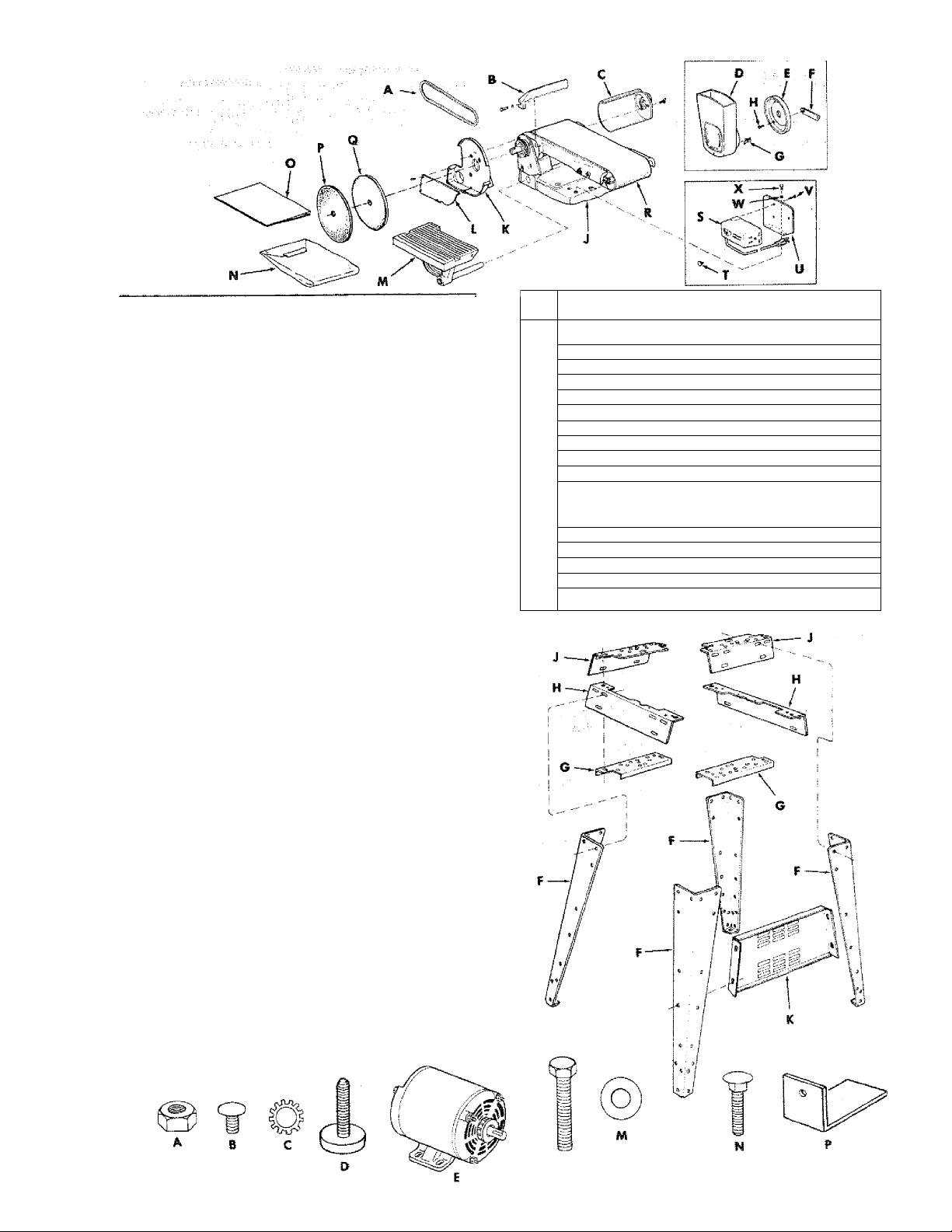
item
V-Belt, 1/2 X41"
A
Backstop ......................................................... ^
B
Belt, Dust Trap ................................................ ^
C
Motor Pulley Belt Guard .................................. 1
D
Belt Guard Support ......................................... 1
E
Belt Guard Support Bracket ............................ 1
F
"S" Clip ............................................................ 3
G
Pan Head Screw, Type 23,10-32 X 1/2
H
Base and Belt, Table {w/Sanding Belt)
J
Disc Dust Trap ................................................ 1
K
Dust Trap Cover
L
Work Table ...................................................... 1
M
Bag (containing the following loose parts!
N
(Part No. 68035)
Motor Pulley, 2 In. Dia................................... 1
Wrench, 1/2" .................................................... 2
5/32 Setscrew Wrench
Flat Head Machine Screw 10-32 X 1-3/4
Table of Loose Parts
..............................................
.............................................
.................................
..........
............
.....
1
3
1
^
1
4
assembly
The following parts are included with Mode! 113.225931
ONLY.
Item
No. Oty.
‘Loose Parts Bag Part #68062 Containing Following Items;
*A Nut, Hex Head 1/2-13 ................................................ 8
*A Nut Hex 1/4-20.......................................................... 32
*B Screw Truss Hd. 1/4-20 x 5/8
*C Lock washer, 1/4 External
*D Foot, Leveling
E Motor
E Leg ............................................................................. 4
G Channel, Support
H Stiffener, Side ............................................................ 2
J Stiffener, End ........................................................... 2
K Support, Motor ........................................................... 1
P Bracket, Mounting
HARDWARE FOR MOUNTING TOOL & MOTOR
*L Screw, Hex Hd. 5/16-18 x 1-1/2
*C Lockwastier Ext. 5/16
*A Nut, Hex 5/16-18 ...................................................... 6
*M Washer 11/32 ID
*N Bolt, Carriage 5/16-18 x 3/4 .................................... 4
.........................................................................
...........................................................
.....................................................
.....................................................
......................................................
...................................
.......................................
.............................
..........................................
32
32
4
2
.... 1
.... 1
.... 1
.... 1
___
.... 1
.... 1
.... 1
.... 1
.... 1
.... 3
.... 2
.... 2
Qty.
.... 5
. 1
1
. 1
Item
Pan Head Screw, Type 23 8-32 x 3/8
Flat Washer, 21/64x7/3x1/8
Hex, Head Machine Screw 5/16-18x1 ,, ,.
Screw, M Pan Hd. 10-32x9/16
Lockwasher No, 10 Int. Tooth
Hanger, Cable .........................................
Owner's Manual
0
9" Abrasive Disc .........................................
P
Sanding Disc (w/Set Screw)
Q
Belt,Sanding..............................................
R
Bag Assembly, Outlet (Part No. 68064)
—
(Containing the f ollowing loose parts);
Outlet, on/off Power
S
Switch Key
T
Bracket, Switch Mounting
u
Screw, Pan Hd. 8x3/8 ........................
V
Lockwasher, 1/4"
w
Screw; Pan Hd. Machine 1/4-20 x 1/2 ....
X
1
1
2
6
6
Table of Loose Parts
.....
....................
................
.................
.........................................
......................
...............................
............................................
......................
..................................
Page 8
Î^ObiËL 113iZ2S^
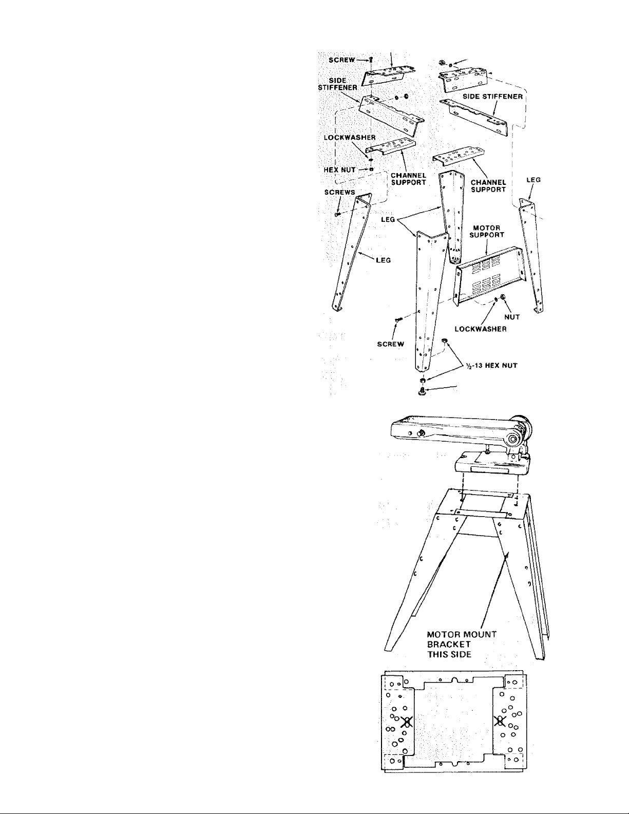
i . AssertIbtS; the: tw^ the two (2)
Side Stiffeners using four (4) 1/4-20 Truss head
screwsi The EndiStiffeners are piaced on top of each
Side Stiffener as shbyyn. insert screws through the
; ,9/3Z: inch dianieter holes and finger tighten 1/4-20
END STIFFENER HEX NUT
i ^LOCKWASHER
STIFFENER
END
2, Attach the four (4) legs to the side and End Stiffener
using 1/4-20 screws, lockwashers and nuts as shown.
3: Rerhove!the four (4) Truss head screws which were
assembled: in Paragraph No, One. Place the two (2)
; Support Channels as shown, in position, align holes in
supports with holes in the :Stiffeners, replace
ipckwashers and nuts. Tighten all nuts using 7/16"
//;wrenchv:::,: ' . .
4. Assemble the motor support tosteel legs with 1/4-20
screws and nuts. Motor support can bemounted to
5i Install leveling feet as shown. To level Leg Set, loosen
nut on: inside of leg and turn nut on outside to raise
Adjust all: four ievelers, if necessary,
and then tighten nuts on inside of leg.
: :: NOTE: These levels are not intended for height
adjustment. .....................: i:-, .■
WHEN Installing OR moving the sander.
Avoid DANGEROUS environment. Use the sender in a
drVf indoor placé protected from rairi. Keep work area well
lighted. ■. .. ■ ' : ;■ ■■ ■ ^ \ :: , V
Place the sander so neither the user nor bystanders are
forced to stand iii tine with the abrasive belt or disc:
To aWid injury from unexpected sander movement:
*: Put the sander oh a firm level surface where there is plenty
of room for handling and properly supporting thé
workpiece, .. . : , : : :
• Supportthe sander so it does not rock.
• Bolt the sander to the floor or work surface if it tends to slip,
walk, or slide during normal use. :
To avoid back injury, get help or use recommended casters
when you need to move the sander. Always get help if you
need to lift the sander.
NEVER STAND ON TOOL. Serious injury could occur if the
tool tips or you accidentally hit the cutting toot. Do not store
anything above or near the tool where anyone might stand on
the tool to reach them.
LEVELING
FEET
SCREW
MOUNTfNG BELT AND DISC SANDER ON
CRAFTSMAN STEEL LEG SET.
catalog NO. 9-22236
NOTE; Forillusfrativepui'posesj the Belt and Disc Sander is
shown mounted on the Craftsman Cataiog No. 9^22236
Steel Leg Set. This Leg Set is included with Model No.
113.22593r. :■ ;: v " ■ ■■
Page 9
1. Place the Belt and Disc Sander on the Steel Legs,
position as shown, and align the mounting holes in
the feet of the Belt and Disc Sander with those in the
END STIFFENERS (marked with an X in the
illustration)!
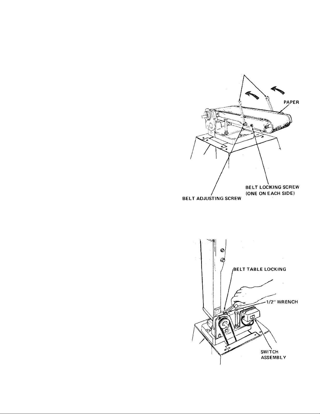
NOTE: The abrasive belt is shipped detached. To
install the belt on the machine:
1. Loosen both belt LOCKING screws, using the 1/2"
wrench furnished with the machine.
2. Turn both of the abrasive belt AJUSTING screws as
shown until they stop. Retighten the two belt LOCK
ING screws so that the idler pulley does not come out
3. Remove the piece of paper.
4. Remove the protective coating, that is applied at the
factory, from the belt table. Use any ordinary house
hold type grease and spot remover.
2. Mount to legs using two 5/16-18 x 2-1/2" hex head
screws, flat washers, external lockwashers, and hex
nuts.
1/2" WRENCH
WARNING: Never use gasoline, naptha, or similar
highly volatile solvents.
NOTE: Do not apply wax to the belt table.
INSTALLING SANDING DISC AND DUST
TRAP
1. Loosen the belt table locking bolts behind the mount
ing bracket using one of the 1/2" wrenches supplied
with your machine.
2. Position belt table vertically and tighten only one of
the bolts.
3. Place the V-Belt over the pulley.
4. Attach the switch assembly to the base using the two
screws and washers packed with the switch.
5. Loosen the bolt that you tightened in step 2. Position
the belt table horizontally, and tighten both bolts.
(ONE ON EACH SIDE)
Page 10
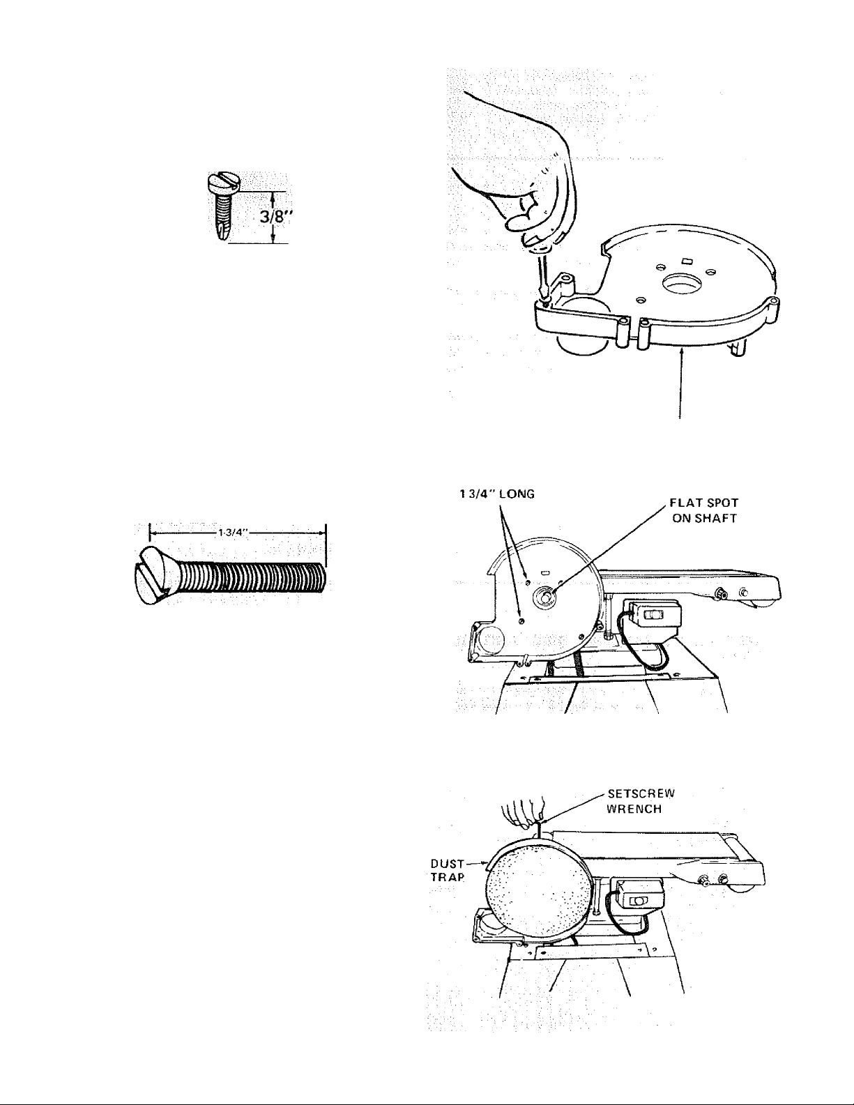
6. Fiind five; 3/Ö'' Pan Head iSelf-Trcàdtng screws from
'W/îamorigitHeddoi^ y :.. ■^ :^;y
7. Place Disc Dust Trap on your workbench and screw in
five Pan Head "Thread Gutting Screws," 3/8" long.
Screw them in all the way.
NOTE: The holes in theTrap are not threaded but the
screws are "Thre^ Cutting Screws" and will cut a
thread as they arc tightened.
DISC DUST TRAP
8. Find four Flat Head Machine Screws 1-%"lohg from
among the loose parts
9; Attach thé Disc Dust Trap with four flat head screws
10. There is a flat spot on the shaft near the end. Rotate
the shaft so that the flat spot is facing up.
11. Place the disc on the shaft so that the set screw is
facing up. Position the disc SO that it is approx. 1/16
inch outward from the edge of the dust trap. :
12. Insert the long end of the 5/32" setscrew wrench
through the hole in the disc housing and into the
. setscrew in the disc. Make sure setscrew is aligned
/with "Flat" on shaft. ■ .
FLAT HEAD SCREWS
5/32 INCH
NOTE: After several hours of operation, check for
i; ■ y . looseness of setscrew and retighten. .
13: Make certain that the metal disc is free of oil and
grease then peel the backing from the 9" abrasive disc
and affix to the sanding disc, ; y
10
Page 11

14, Remove the top right hand screw which you installed in
step 6 and loosen the other three screws.
15. Install the Dust Trap cover and replace the top right
hand screw. Tighten all five screws.
INSTALLING
MOTOR, V-BELT, AND
BELT GUARD
1. Locate the following parts:
QTY. Description
1 Motor
1 "L" Bracket
1 Pulley (approx. 2" Dia.)
1 V-Belt
4 Carriage Bolt 5/16-18 X 3/4
4 Fiat Washer 5/16 i.D.
4 Lockwasher 5/16 I.D.
4 Hex Nut 5/16-18
1 Guard Assembly including a guard support,
guard support bracket, self-threading screws,
and clips.
2. Place motor against the motor mounting bracket and
insert bolts through holes in motor base and then
through holes marked "X" in motor mounting bracket.
DO NOT TIGHTEN BOLTS AT THIS TIME. The "L"
bracket which holds the guard support must be slid
between the motor base and the motor mounting
bracket so motor must be loosely assembled to bracket
at this time.
.........
Slide long leg of "L" bracket between motor base and
motor mounting bracket. Then sandwich the "L" bracket
between the guard support bracket and the guard
support and fasten together with self-threading screws
as shown. Install clips onto belt guard support.
Install the 2" pulley onto the motor shaft flush with the
end of the shaft and tighten the set screw in the pulley
hub against the flat part of the motor shaft.
11
Page 12

5' Riacebèltovër machiné puile^^^ bell into
thé open, end of the guard anci oiit the round openi ng.
MAKE SURE BELtHÀS NOT SLIPPED OFF OF
MACHINE PULLEY FROM STEP 3> DISC AND
DUST TRAP INStALLAtlON.
6 Place the belt onto the motor pulley by rotating the
pulley.
7. Move the motor sideways so that the belt is in the
center of the opening in the top of the base. Visually
tine up the pulleys and V-belt.
8. PUSH dovvrivya rd on motor to apply tensi o n to belt a nd;
tighten motor bolt huts. ^
9. Check guard support before tightening guard support
screws. Guardsupportmustbecenteredaroundmotor
shaft. Tighten screws.
10. Push guard into position on guard support.
ON-OFF SWITCH
WARNIIMG: DON'T CONNECT POWER CORD TO
SURE MOTOR ROTAtlON IS CORRECT. SEE PAGE 5,
The On-Off Switch has a locking feature. THIS FEATURE IS
INTENDED TO PREVENT UNAUTHORIZED AND POSSIBLE
HAZARDOUS USE BY CHILDREN AND OTHERS.
1, Insert key into switch.
NOTE: Key is made of yellow plastic
12
Page 13

2. Tp turn machine on, insert finger under switch lever
and pLill end of switch out.
3. To turn machine OFF . , . PUSH lever in.
Never leave the machine unattended until it has come
to a complete stop.
4. To lock switch in OFF position . . . hold switch IN
with one hand . . . REMOVE key with other hand.
WARNING: FOR YOUR OWN SAFETY, AL
WAYS LOCK THE SWITCH "OFF" WHEN
MACHINE IS NOT IN USE . .. REMOVE KEY
AND KEEP IT IN A SAFE PLACE . . . ALSO
... IN THE EVENT OF A POWER FAILURE
(ALL OF YOUR LIGHTS GO OUT) TURN
SWITCH OFF ... LOCK IT AND REMOVE THE
KEY. THIS WILL PREVENT THE MACHINE
FROM STARTING UP AGAIN WHEN THE
POWER COMES BACK ON.
5. Find plastic cable hanger from among the loose parts.
6. Route the motor cord behind the motor mount,
across the top of the base and plug it into the
receptacle in the side of the switch box,
7. Bring the power cord alongside the motor cord . . .
wrap the plastic cable hanger around the cords and
attach the hanger to the top of the base by pushing
it into a %" diameter hole.
CABLE
HANGER
MOTOR
Page 14

assembly
INSTALLING WORK TABLE
NÖTE; Apply cisat bf paste wax to the work table.
This will make it a little easier to feed.the work; ^
1. Loosen the table positioning screw,
2. Iiisert the table support rod in the hole in the base
until the edge of the table is approximately 1/16"
from the abrasive disc. Tighten the screw.
NOTE: There is a second mounting hole in the base. This
is for mounting the table when the belt is used in a ver
tical position. ; ;
WARNING: To avoid trapping the work or fingers be
tween the babie and sanding surface, the table edge
shbuid be a maximum 1 /16 inch from the sanding
surface, the table should be completely engaged on
the rod.
INSTALLING ABRASIVE BELT-TENSlONlNG
AND TRACKING
WARNING: FOR YOUR OWN SAFETY, TURN
SWITCH "OFF" AND REMOVE PLUG FROM
POWER SOURCE OUTLET BEFORE REMOV
ING OR INSTALLING ABRASIVE BELT.
On the smooth side of the abrasive belt you will find a
"directional arrow." The; abrasive beh must run in the
direction of this arrow so that the splice does not coihe
apart. ■; ■ ■ ■ ' ■ ■ . ■ ■ ■ ■
1. Loosen the two abrasive belt LOCKING screws.
2. Place the abrasive belt over die pulleys with the direcv
; tional arrow pointing as shown. Make siire the abra
sive belt is centered on both pulleys.
Turning the abrasive belt ADJUSTING screws will cause
the idler pulley to move in or out. When the idler pulley
is moved outward, it puts TENSION on the belt.
3, Place both of the Vi" wrenches on the ADJUSTING
screws and puli the wrenches toward you. This will
stretch the abrasive belt. Move the wrenches back and
forth a few times so that you "get the fee!" of the
abrasive belt while it is stretching (TENSIONING),
PULL WRENCHES IN THIS
DIRECTION TO APPLY
TENSION
DIRECTIONAL ARROW
BELT ADJUSTING SCREWS
BELT LOCKING SCREW
Apply a small amount of TENSION to the abrasive
belt by pulling the wrenches toward you, so that the
TENSION feels the sarhe on both wrenches.
14
Page 15

4. Hold the abrasive disc with your left hand to keep it
from turning while pushing the belt in the direction
■ of the arrow. If the abrasive belt slips over the
pulleys, turn both ADJUSTING screws
simultaneously a small amount to apply a little more
tension to the abrasive belt.
6. Adjust the tension so that the abrasive belt does not
slip very easily when pushing it, while you are holding
the disc.
6. Tighten the locking screws,
7. Plug in the power cord. Turn the switch "ON", and
immediately "OFF", noting if the belt moved to the
right or to the left.
H it did not move to the right or left, it is
TRACKING properly.
8. IF THE ABRASIVE BELT MOVES TO THE
RIGHT:
a. Loosen the LOCKING SCREW on the RIGHT.
b. Place wrench on the ADJUSTING SCREW on the
right,
c. Push abrasive belt so it is moving while pulling the
wrench toward you. This will move the abrasive
belt to the left. PUSHING the wrench will move
the belt to the right
d. The abrasive belt is tracking properly when it is
centered on the DRIVE pulley.
IMPORTANT: If you have difficulty tracking the
abrasive belt, apply more tension.
PUSH BELT IN DIRECTION
OF ARROW
BELT
LEFT
MOVING
9. IF THE ABRASIVE BELT MOVES TO THE LEFT:
a. Loosen the LOCKING SCREW on the LEFT.
b. Place wrench on the ADJUSTING SCREW on the
left.
c. Push abrasive belt so it is moving while pulling the
wrench toward you. This will move the abrasive
belt to the right. PUSHING the wrench will move
the abrasive belt to the left.
d. The abrasive belt is tracking properly when it is
centered on the DRIVE pulley.
IMPORTANT: If you have difficulty tracking the
abrasive belt, apply more tension.
INSTALLING BELT DUST TRAP
1. Find one 10 • 32 X 9/16" Pan Head screw and a lockwasher among the loose parts.
15
Page 16

:.-:'i.:-'ÈélòWLtKe;suriacé^W
top. ■
BACKSTOP
IMSTALLtNG BACKSTOP
1, Find one 5/16" X 1" Hex. Head bolt and one flat
washer among the loose parts.
2. Place the washer on the bolt, and screw it halfway
into the mounting hole. Place the backstop into pos
tion and tighten the bolt. When removing the backstoh, loosen the bolt bMt do not remove it.
9eft!ng to know yoiir bèlt and disc sander
WARNING; FOR YOUR OWN Safety TURN
SWITCH "OFF" AND REMOVE PLUG FROM
POWER SOURCE OUTLETBEFORE MAKING
ANY ADJUSTMENTS.
ABRASIVE DISC
4 BACKSTOP
LOCK SCREW
BACKSTOP
1 BELT ADJUSTING
SCREW
(ONE ON EACH SIDE)
BACKSTOP
BACK OF SANDER
WORK
TABLE
3 WORK TABLE 0 BELT
TILT LOCK SCREW STOP SCREW ^
; , : ; i (ONE ON EACH SIDE)
front OF SANDER /
TABLE 2 BELT LOCKING
.........................
16
IDLER
PULLEY
Page 17

1. ABRASIVE BELT ADJUSTING SCREWS
cause the idler pulley to move irt or out for applying
tension to the abrasive iaelt or for tracking it. They
are adjusted using the 1/2" wrenches.
See "Assembly" section ,. . "Installing Abrasive Belt".
2. ABRASIVE BELT LOCKING SCREWS lock
the adjustment mechanism after the abrasive belt is
tensioned and tracking properly. They are locked
using the 1/2" wrench.
BELT ADJUSTING
See "assembly" section . ,
, "Installing Abrasive
Belt".
3. WORK TABLE TILT LOCK SCREW locks
the table. It is locked using the 1/2" wrench.
a. Using a combination square, check the angle of
the table widi the disc.
NOTE; The combirration square must be '"true"—
See start of assembly section on Pg. 6 for checking
method.
b. If the table is not 90® with the disc . . . loosen
tilt lock screw and tilt table.
c. Loosen the lock nut using a 7/16" wrench,
SCREW
(ONE ON EACH SIDE!
d. Strew the stop screw in or out, using a 3/8"
vwrench so that when ithe table touches the stop
screw, the table is 90° to thé disc.
e. Tighten the lock nut.
17
Page 18

getting to know
f. Loosen the tabie positioning lock screw.. . ppsi-
tion the table approximately 1/16" ayyav ffP't’
the abrasive disc. ^ ^ ^ _
g. Tilt the table downward but don't tighten the lock
screw, and position it as close to the disc as ppssible. Using the head of a combination square,
check the angle of the table with the disc.
h. If the table is not 45° with the disc:
i. Raise the table and loosen the lock nut using a
7/16" wrench.
j. : Screw the stop screw in or out, using a 3/8'
wrench so that when the table touches it,: it is 45
with the disc. ■; '
k. Tighten the lock nut.
WARNING: To avoid trapping thé work or fingers
between the tabie and sanding surface; the table must
be repositioned on the rod to maintain a maximum
1/16 inch space between the table and sanding
surface.
on
ISC sonder
4 BACKSTOP LOCK locks the backstop in
place. It is locked using the 1/2" wrench.
5. BELT TABLE LOCKING BOLTS ... lock the
belt table in position. /
To adjust to vertical position; :
a. Remove the backstop,
b. Loosen the two beit table locking bolts using the
1/2" wrench sullied with your machine.
c. Position belt table vertically and tighten the two
bolts.
6. ABRASIVE BELT TABLE STOP can be adj
usted so that the abrasive belt table is level with
the floor w4ien in ahorirontai position.
a. Loosen the lock nut using a 3/4" wrench.
........ ...............
BACKSTOP
BACKSTOP
b, PI ace a level on the abrasive bel t table and using a
3/4-' wrench, screw the stop bolt in or but until
theTableis;ieyel.':\ ■■■' . - ■
18
Page 19

asic ©perofion
BEFORE USING THE SANDER: ^ ^ ^
WARNING: To avoid mistakes that could cause serious, per
manent injury, do not plug the sander in until the following
steps are completed.
• Assembly, (See pages 7-16.)
• Learn the use and function of the ON-OFF switch,
backstop lock screw, bell adjusting screws, belt tocking
screws, work table and work table tilt lock screw. {See
pages 16-18.)
• Review and understanding of all safety instructions and
operating procedures in this manual.
« Review of the maintenance methods for this sander.
(See page 22.)
BEFORE EACH USE;
Inspect your sander.
DISCONNECT THESANDER, To avoid injury from accidental
starting, unplug the sander, turn the switch off and remove
the switch key before changing the setup, sanding disc or
belt or adjusting anything.
CHECK DAMAGED PARTS. Check for;
® alignment of moving parts,
• binding of moving parts,
• broken parts,
• stable mounting, and
9 any other conditions that may affect the way the sander
works.
If any part is missing, bent, or broken in any way, or any
electrical parts don't work properly, turn the sander off and
unplug the sander. REPLACE damaged, missing, or failed
parts before using the sander again,
MAINTAIN TOOLS WITH CARE. Keep the sander clean for
best and safest performance. Follow instructions for lubri
cating.
REMOVE ADJUSTING KEYS AND WRENCHES from tool
before turning it on.
To avoid injury from jams, slips or thrown pieces:
• USE ONLY RECOMMENDED ACCESSORIES. (See
page 22.) Consult this Owner's manual for recommended
accessories. Follow the instructions that come with the
accessories. The use of improper accessories may
cause risk of injury to persons.
• Adjust table to dear the sanding surface by no more than
1/16bf an inch.
» Make sure alt clamps and locks are tight and no parts have
excessive play.
• KEEP WORK AREA CLEAN. Cluttered areas and benches
invite accidents. Floor must not be slippery.
To avoid burns or other fire damage, never use the sander
near flammable liquids, vapors or gases.
Plan ahead to protect your eyes, hands, face, ears.
KNOW YOUR SANDER. Read and understand the owner's
manual and labels affixed to the tool. Learn its application
and limitationsas well as the specific potènti al hazards pecu
liar to this tool.
To avoid injury from accidental contact with moving parts,
don't do layout, assembly, or setup work on the sander while
any parts are moving.
AVOID ACCIDENTALSTARTING. Make sure switchis "OFF"
before plugging sander into a power outlet.
Plan your work.
USETHERiGHTTOOL.Don'tforcetoolorattachmenttodoa
job it was not designed to do.
CAUTION: This machine is not designed for heavy deburring
operations. When finishing metals, sparks or hot fragments
could cause a fire. To avoid this, disconnect any dust col
lecting hose from the sander. Also, remove alt traces of wood
dust from inside dust traps in the sander.
Dress for safety.
Any power sander can throw foreign objects into the eyes. This
can cause permanent eye damage. Wear safety goggles (not
glasses) that comply with ANSI Z87.1. Everyday eyeglasses
have only impact resistant lenses. They are not safety glasses.
Safety goggles are available at Sears retail catalog stores.
Glasses or goggles not in compliance with ANSI Z87,1 could
seriously hurt you when they break.
• Do not wear loose clothing, gloves, neckties or jewelry
(rings, wrist watches). They can get caught and draw you
into moving parts.
9 Wear nonslip footwear.
9 Tie back long hair,
9 Roil long sleeves above the elbow.
• Noise levels vary widely. To avoid possible hearing dam
age, wear ear plugs or muffs when using sander for hours at
a time.
9 Sanding operations are usually dusty. Wear a dust mask
along with the safety goggles.
Inspect your workpiece.
Make sure there are no nails or foreign objects in the part of
the workpiece to be sanded.
Plan your work to avoid THROWBACKS—when the work
piece catches on the sanding beit or disc and is torn from you r
hands.
• Make sure there's no debris between the workpiece and its
supports.
• When sanding irregularly shaped workpieces, plan your
work support so it will not slip and be pulled from your
hands.
Use extra caution with large, very small or awkward work
pieces:
• Never use this tool to finish pieces too small to hold by
hand.
• Use extra supports (tables, saw horses, blocks, etc.) for
any workpieces large enough to tip when not held down to
the tabletop.
• NEVER use another person as a substitute for a table exten
sion, or as additional support for a workpiece that is longer
or wider than the basic sander table, or to help feed, sup
port or pull the workpiece.
• When finishing on the Disc, always press the workpiece
against the "Down" side of the disc. Sanding against the
side coming up from under the table could damage the
work by making it "chatter," or tear the work from your
hands and throw it,
• Sand only one workpiece at a time.
• Cleareverythingexceptthe workpieceandrelated support
devices off the table before turning the sander on.
19
Page 20

bosic operation
Plan the way you will hold the workpiece from start to finish.
Avoid awkward operatibns and hand positions yvhere a sud
den slip could cause fingers or hand to move into a sanding
surface. Keep fingers away from wherethebeitgoesintothe
dust trap,
DON'T OVERREAC H, Keep good footing and balance.
Keep your face and: body to one sjde, out of tine with a pos
sible throw/back. ;
WHENEVER SANDER IS RUNNING.
WARNING: Don't let familiarity (gained from frequent use of
yoUr belt and disc sander) cause a careless inistake. A care
less fraction of a second is enough to cause a severe injury.
Before starting your Cut, watch the sander While it runs. If it
rhak^s ah unfamiliar noise or vibratesa lot. Stop immediately,
■Turn the sander off. Unplug the sander. Do not restart until
finding arid correcting the problem..
Make sure the sanding disc turns counterclockwise before
. using the sander. . : ■ ■ : : ; ; . :
SURFACE FINISHING ON THE
■;ABFtAsiVE:'BELT.
KEEPGHILDREN AWAY, Keepall visitors asafedistance from
the sander. Make sure bystanders are clear of the sander and
workpiece. ^
DON'T FORCE TOOL, it will do the job better and safer at its
designated rate. Press the workpiece against the sanding
material only hard enough to let it sand without bogging
down or binding. :
Before freeing any jammed material;
• Turn switch "OFF."
• Unplug the sander.
• Wait for all moving parts to stop.
To avoid throwback of the workpiece, use workpiece supports
for ail flat surface sanding.
BEFORE LEAVING THE SANDER;
Waitfor all moving parts to stop.
Make workshop child-proof. Lock the shop. Disconnect
master switches. Remove the yellow switch key. Store it
away from children and others not qualified to use the tool.
f.FLATSUBFAdES. .'tv .
Ftold the work piece firmly with both hands, keeping
fingers away from riie abrasive belt.
Keep the end bu^ed against the backrtop and move the
work evenly across the abrasive belt. Use extra caution
when finishing very thin pieces.
For finishing long pieces* remove the backstop.
Apply only enough pressure to etiow thè abrasive belt
to remove material, if the abrasive belt stalls and the
belt pUtteys slip ; while ¡applying irioderate pressure
the workpiece, the abrasive belt requires more tension.
END FINISHING ON THE
ABRASIVE BELT.
It is more convient to finish the ends of long work
pieces with the abrasive belt in a vertical position.
Move ihe work eveniy across *e abrasive belt. For
accuracy, use a miter guage. ;
The table may be tilted for beveled work.
Getting To Know Your Finishing Machine section
for adjusting thé abrasive belt table and the work table.
20
Page 21

FINISHING CURVED EDGES ON THE
ABRASIVE BELT
CURVED EDGES
Finish outside curves on the abrasive belt and inside
curves on the idier pulley.
FINISHING SMALL END SURFACES AND
CURVED EDGES ON THE ABRASIVE DISC
Move the work across the "Down Side" of the face of
the abrasive disc. For accuracy, use a miter gauge.
NOTE; Use a combination square to square the miter
gauge to the face of the disc, if it is not square, pull out
the index pin, loosen the miter gauge knob and move the
miter gauge slightly until it is square. Without moving
the miter gauge, tighten the knob securely-
Applying the workpiece to the "Up Side” could cause it
to fly up (kickback) which could be hazardous.
The table may be tilted for beveled work.
Page 22

riMiifeiiarîcé
WARNING: FOR YOUR OWN SAFETY> TURN
SWITCH "OFF'' AND REMOVE PLUG FROW
POWER SOURCE OUTLET BE FORE ADJUST
ING, MAINTAINING, OR LUBRICATING
YOUR FINISHING MACHiNE.
Keep your machine and your workshop clean. The dust
traps around the abrasive disc and the abrasive belt are
designed to deflect most of the fine dust. They should be
connected to a Vac for most efficient dust removal.
WARNING: DO NOT ATTACH A VACWHEN FINISHING
IRON OR STEEL. THE SPARKS COULD IGNITE THE
DEBRIS AND CAUSE A FIRE.
tf power cord is worn or cut, or damaged in any way,
have it replaced immediately.
Frequently Wow out any dust that may accumulate
inside the motor.
A coat of automobile-type wax applied to the work
table will make it a little easier to feed the work while
finishing.
Do not apply wax to the abrasive belt table because the
belt could pick up the wax and deposit it on the pulleys,
causing the’belt to slip.
MOTOR MAINTEMAWCE AMD
LUBRICATiOM
1. The bearings, in both end shields of the motor, have been
lubricated at the factory with correct lubricant. No other
part of the motor requires lubrication.
2. Re-lubricate motor bearings in accordance with the
instructions on the nameplate. Be sure to wipe oil dirt or
grit if present around oil hole caps to prevent any possibility
of foreign material contaminating the oil wicks that supply
the bearings with oil. Use a good grade of medium weight
mineral oil. such as automobile engine oil, SAE 20.
3. If disassembly of the motor is necessary, it should be
returned to your nearest Sears retail or mail-order store in
order to prevent voiding the guarantee.
NOTE: The speed of this rnotor cannot be regulated or
changed.
4. Every effort should be made to prevent foreign material
from entering the motor. When operated under conditions
likely to permit accumulations of dust, dirt, or waste within
the motor, a visual inspection should be made at Irequent
intervals. Accumulations of dry dust can usually be blown
out successfully.
NOTE: Motors usedon wood working tools are particularly
susceptible to the accumulation of sawdust and wood chips
and should be blown out or "vacuumed" frequently to
prevent interference with normal motor ventilation and
proper operation of the centrifugaliy-operated starting
switch.
iiibricafiori
The BEARINGS in this machine are packed with grease at
the factory. They require no further lubrication.
Periodically 1 ubricate the cams and shafts in the idler pulley
mechanism with Silicon Spray;
.................
,
SEARS RECOMMENDS THE
FOLLOWING ACCESSORIES
ITEM CAT. NO.
Steel Stand
Caster Set . .............................................
Niiter Gauge .............................................................. 9-29929
Pressure-Sensitive cement
Abrasive Belts and Disc
Steel Legs
Power Tool Know How Handbooks
Radial Saw .............................................................
Table Saw .................................................................9-2918
Sears may recommend other accessories not listed in the
manual. See your nearest Sears store or catalog department
for other accessories. Do not use any accessory unless you
have received and read complete instructions for its use.
...
..............................................................9-22213
..........................................
..............................
................................................................
9-22222, 9-22221
SEE CATALOG
9-22236
9-2917
9-2220
22
Page 23

trouble shooting
WABWING: FOR YOUR OWN SAFETY, TURN
SWITCH "OFF" AND REMOVE PLUG FROM
POWER SOURCE OUTLET BEFORE TROUBLE
SHOOTING YOUR SANDER,
TROUBLE SHOOTING CHART
TROUBLE
Motor wit! not run.
Machine slows down
when finishing.
Abrasive Belt Slips
Abrasive Belt runs
off pulleys.
Wood burns while
finishing.
PROBABLE CAUSE
1. Defective On-Off switch.
Defective switch cord.
Defective switch box receptacle,
2. Motor protector open, (only if
your motor is equipped with an
overload protector),
3. B u rn ed ou t mo to r.
1. V-Belt too loose.
2. Applying too much pressure to
workpiece.
3. Too much tension on abrasive
belt.
1. Not enou^ tension.
1. Not tracking properly ,
2. Not enou^ tension.
. . .
1. Abra&ive disc or belt is glaz^ with
sap.
REMEDY
1. R e pla ce d ef ec tiv e pa rts b ef ore u sin g be lt disc
Sander aga in .
2. Res e t p rot ec to r a fte r mo to r h a s c oo le d.
3. C on su lt Se a's S e ivic e . A ny a tte m pt to re pa ir thi s
mo tor m ay c re ate a H AZ A RD u n les s firp a ir i s
don e by a qu al ifie d se rv ice t ec hn ici ar ,. R e pa ir
ser vic e is av ail ab le at yo ur n ea re st Se a rs St ore .
1. Increase belt tension, see Assernbly Section,
"Motor Pulley Belt Guard and Motor
Installation."
2. Ease up on pressure.
3. Adjust tension, see Assembly Section, "Installing
and Adjusting Abrasive Beit."
1. Adjust tension, see Assembly Section, "Installing
and Adjusting Abrasive Belt."
1, Adjust tracking, see Assembly Section, "Instaliirrg
and Adjusting Abrasive Belt."
2. Adjust tension, see Assembly Section, "installing
and Adjusting Abrasive Beit."
1, Replace disc or belt.
23
Page 24

TROUBLE SHOOTING - MOTOR
NOTE: Motors used oti wopd'Wbrking tools are particularly susceptible to the accumulation
of saviidust ànd Wdod chips and should be blown out or “vacuunied” frequently to prevent
Ititérferericé with, noritial motor: ventilation and proper operation of the centrifugally-
,;dperated'startirig;switch:/ ^ / .
TROUBLE
EKcesslve hofse.
Motor fails to develop
lull power. NOTE;
LOW VOLTAGE: (Power
output of motor
.decreases rapidly with . ;
decrease.iii voltage at .
motor terminals. For
exarhple, a reduction of
. 10% iri voltage causes : .
a reductiori of 19% in
rnaxtmum power butpüt
. of'Which the fn otor is
capable, and a reduction
of 20% in voltage causes
a reduction of 36% in ■
maximum power output.)
Motor starts slowly
òr fails to cóme up
to full speed.
PROBABLE CAUSE
1. Motor. 1. Have rpotor checked by qualified service
1. Circuit overloaded with
lights, appliances and
other motors.
2. Undersize wires or circuit
too long. ;
,3. General overloading of
power company
facilities. .
IV Low voltage Will not
trip relay: :
2. Windings burned out
Of open ;
3. Starting relay not
operating, .
technician. Repair service is available at
your nearest Sears store,
1. Do not use other appliances or motors on
same circuit when using the saw.
2. Increase wire sizes, or reduce length of wiring.
See. "Motor Specifications and Electrical
. : Requirements" section.
3. Request a voltage check from the power
company.
1: Request voltage check from the power company,
2. Have motor repaired or replaced.
3. Have relay replaced- ..........................
REMEDY
Motor overheats.
Starting switch iri
motor will not
operate.
Motor stalls
(resulting in blown
fuses or tripped
circuit breakers).
Frequent opening of
fuses or circuit
breakers.
t: Motor overloaded-
2. Improper^cooling: (Air
. circulafipn restricted:
: through motor due to
sawdust, accumulating.
1, Burned switch contacts :
(due to extended .
hold-in periods caused
by low line voltage, etc )
2, Shorted capacitor
3, Loose or broken
connections.
1. Starting switch not
operating.
2. Voltage loo low to permit
motor to reach operating
speed.
3. Fuses or circuit breakers
do not have sufficient
capacity.
1. Motor overloaded.
2. Fuses or circuit, breakers
do not have sufficient
: capacity, .■ ;
3. Starting svvitch not
, operating. (motor does
not reach speed).
1. Feed work slower into belt or disc.
•2- Clean out sawdust to provide normal air
circulation through rnotor.
■ See "Maintenance and Lubrication" section.
1. Have switch replacedand request a voltage check
: from the power company.
2. Have capacitor tested and replace if defective.
3. Have wiring checked and repaired.
1. Have switch replaced.
2. Request voltage check from the power company.
3. Install proper size fuses or circuit breakers.
1, Feed work slower into belt or disc.
2, Install proper size fuses or circuit breakers.
3, Have switch replaced.
24
Page 25

repair parts
CRAFTSMAN BELT AND DISC SANDER MODEL NO. 113.225900 & 113.225931
J
FIGURE 1 PARTS LIST
SUPPLIED WITH MODEL 113.225931 ONLY
Key
No.
10
Part
No.
62 SI 4
1
60314
2
STD541Q25
3
STD551225
4
68060
5
68059
6
62615
7
68061
8
STI1541050
9
803835
68062
tTheSB items all contained in Loose Parts Bag, Part No. 68062.
Leg
t Screw, Truss Hd. 1/4-20 x 5/8
t*Nut, Hex 1/4-20
T* Lockwasher, 1/4 External
Channel, Support
Stiffener, Side _
Stiffener, End
Support, Motor
t*Nut, Hex 1/2-13
t Foot, Leveling
t Bag of Loose Parts (Not illustrated)
Description
Key
No.
HARDWARE FOR MOUNTING TOOL & MOTOR
—
Part
No.
STD523125
STD551131
STD541231
STD551031
STD532507
^Standard Hardware Item - f^ay be Purchased Locally.
t*Screw, Hex Hd. 5/16-18x2-1/2
t*Lockwasher, External 5/16
t*Nut, Hex Jam 5/16 x 18
t’Washer, 11/32 x 11/16 x 1/16
t*Bolt, Carriage 5/16-18 x 3/4
25
Description
Page 26

m
CRAFTSMAN BEIT AND DISC
SANDER MODEL NO. 113.225900 8.113.225931
Q
-22
17 2.3 17 T
I >_ -Ls
trt
FIGURE 2
Page 27

CRAFTSMAN SELT AND DISC SANDER MODEL NO. 113.225900 & 113.225931
FIGURE 2 PARTS LIST
N)
Key
rjü.
1
2 68033
STD503103
3
4
Part
No.
38834
tDisc, 9 inch Abrasive
Description
Disc, Sanding (w/Set Screwl
‘Screw, Socket Head Set, 5/16-18 x 5/16
30646 tPuMey (w/Set Screw) 2 1/2 dia. x 1/2,
Key
No.
36 47813
37 60254 Bracket. Support
38
39
STD601105
"V" Groove 5/8 bore. Keyed
5 STD600803
'Screw, Type 23, Pan No. 8-32 x 3/8
6 68003 Cover, Housing
7
133656
'Screw, Machine Flat Head No. 10-32
X 1-3/4
8
9 68069
68004 Housing, Disc
Shaft, Drive
10 STD580025 Key, Woodruff, No. 9
11 38812
12
STD523115
ST0551131 'Lockwasher, 5/16 48 68015
13
14
68005 Bracket, Mounting 49
15 STD551031
Key, Woodruff
*Screw. Hex Head 5/16-18 x M/2
'Washer, 21/64 X 7/8 X 1/8
16 68068 Bracket, Tabie Support
17
18 60434
19 STD523110
20 47222
21
22
37158 Ring, Retaining 5/8
Bearing, Bal!
'Screw, Machine Hex Head 5/16-18 x 1
Backstop
47190 Puliey, Drive {w/Set Screw)
STD502502 'Screw, Socket Head Set, 1/4-20
X 5/16
23
24
25
350 9
68006 Trap, Dust
STD5S1210 'Lockwasher No. 10 Ini. Tooth
26 STD511105
27
28
29
30
680 70 Table. Belt 63
STD551037
68007
STD510605
Bearing Balt
'Screw Mach. Pan Hd. 10-32 x 9/16
'Washer, 3/8 x 3/4 x 1/16
Nut, Cam
'Screw, Machine Pan Slotted
No. 6-32 X 7/16
31
32
33
68008
47815
68009
34 68010
ST0510803
36
L__
' Siunildfci HhuJwüre lien'^ May l-Se P^uri:ha’',íXÍ LocaMy.
1 Stock tteoi May IJti ‘fOCunx! through the* Hardware Department oí íthjsI Sear? or Catalog Of<iei Ho;.
Cam, Left Hand
Spring
Cam, Right Hand
Guard, Idler
'Screw, Machine Pan Head
No. 8-32 X 3/8
40 60255 "S" Clip
41
42 STD304410
43
44 47622
ST0571807
45
46
47
50
51
52
53 STD512505
54
55
STD541250
56
STD523107
57
STD523122
58
59
ST0541026
60
STD522512
61
62
64 ST D 57 18 12 ■pi n. Ro il 3/1 6 X 1-1 /4
65
66
87 68072
68
Part
No.
Description
t8eh. Sanding
60253
Support, BeSt Guard
'Screw, Type 23 Pan Head
No, 10-32 X 1/2
60252 Guard, Belt
iV-8elt, 1/2x41"
62023
tPulley, (w/Set Screw) 2" Dia. x 1/2
"V" Groove 5/8 Bore
Shaft, Control
Pin, R-oll 3/16 X 5/8
38538 Ririg, Retaining 5/8
38536 Bearing, Ball
Base
47621
60096
47414
68017
Shaft, Idler
'Wrench Hex,, 5/32
Pulley, Idler
Wrench
'Screw, Machine Pan Head 1/4-20 x 1/2
ST0551125
'Lockwasher, 1/4
100167 'Bolt, Hex. Head. 1/2-13 x 4-1/2
'Nut, Hex., 1/2-13
8o!t, High Strength, 5/16-18 x 3/4
Bolt, High Strength, 5/16-18 x 2-1/4
68016
Support Assembty, Base
'Nut, Hex,, 1./4-20
'Screw, Mac h ine H ex . He ad , 1/4-20 x 1 -1 /4
38738
941 61 87
6B055
680 36 Han ge r, C ab le
Bracket, Table Lock
'Sc rew , T y -'T " 5/ 16 -1 8 X 3,'4
Hex . He ad
Tab ie , W o rk
Motor (Model 113-225931 j ONLY
69184
68073
68035
Bracket, Mounting
Ow ne r's M an u ai ÍNot illu st ra ted )
Bag o f L oo se P a rts (N o ! il ius trs io d!
68064 fiaq of Lo os e Pa rt s ( No t Hkistraied]
Page 28

CRAFTSIVIAN BELT AND DISC SANDER MODEL 113,225931
NOTE:
Key
No,
1
2
■ .3
Part
No.
60306 Screw, 8-32 x 3/8, Thread
64088
64258 ;
Cutting, Slotted, Serrated
■ ■ Hd;, . /■- ■
Cover, Terminal
Cord with Plug
Description
2B
Page 29

MOTOR CONNECTIONS
WARNING: FOR YOUR OWN SAFETY, TURN SWITCH
"OFF" AND REMOVE PLUG FROM POWER SOURCE
OUTLET BEFORE PROCEEDING.
1. Open motor connector box cover located on left end of
motor (viewed from rear of saw) using a flat blade
screwdriver.
2. Remove GREEN SCREW and lockwasher and insert
screw through round metal terminal on the end of the
GREEN wire of power cord with lockwasher between
terminal and motor frame. (See iilus.)
3. Reinsert GREEN SCREW in the threaded hole. Tighten
securely.
4, insert terminal end of WHITE wire on spade terminal
marked T4 on the motor. Push terminal firmly until
seated.
5. Insert terminal end of BLACK wire on spade terminal
marked T1 on the motor. Push terminal firmly until
seated.
6, Close motor connector box being sure that power cord is
seated in the largest strain relief groove, and tighten box
cover screws.
TERMINAL
29
Page 30

Cf?AFTSMAN BELT AND DISC SANDER MODEL NO. 113.225900 & 113.225931
FIGURE 4 PARTS LIST
ON\OFF POWER OUTLET 60382 AND
MOUNTING BRACKET
Key
No.
__ ■ ■
1
2
3
4 60374
5 60376
6
7
8
*Standard Hardware tten^ - May be Purchased LocaiSy.
» Does Not Include Key No. 3,
Order Separately If Required.
tStockllem—May be secured through the Hardware Deparlment Of
' . ; ^ most Sears Retail Stores or Catalog Order Houses.
NOTE; Shipping arrd handling charges for standard hardware items (identified by *) such as nuts, screws, washers, etc., make
: boy trig these ¡terns by mail uneconom ¡cat To avoid shipping and handling charges, you may obtain most of these
locaity. \ V, 'O' ' .. . ; . : . . , '
Part
No.
60382
60375
60378 Housing, Switch
9-22255
448007 Screw, Pan Hd. No. 6 x 3/4
68066
STD600803 *Screw, Pan Hd. Plastite No. 8 x 3/8
• On/Off Power Outlet
Cord, Molded
tKey, Switch
Switch, Locking
Cover, Switch
Bracket, Switch Mounting
Description
30
Page 31

HOTES
31
Page 32

owners
manual
BEL T AND DISC SANDER
SERVICE
MODEL NO.
113.225900
BELT AMD DISC
SANDER ONLY
MODEL NO.
113.225931
BELT AND DISC
SANDER/WITH
LEGS AND MOTOR
HOW TO ORDER
REPAIR PARTS
Now that you have purchased your Belt & Disc Sander should a
need ever exist for repair parts or service, simply contact any
Sears Service Center and most Sears, Roebuck and Co. stores.
Be sure to provide all pertinent facts when you call or visit.
The model number of your Belt and Disc Sander will be found
on a plate attached to your sander at the right-hand side of the
base.
WHEN ORDERING REPAIR PARTS, ALWAYS GIVE THE
FOLLOWING INFORMATION:
PART NUMBER
MODEL NUMBER
113.225900 OR
113.225931
Alt parts listed may be ordered from any Sears Service Center
and most Sears stores. If the parts you need are not stocked
locally, your order will be electronically transmitted to a Sears
Repair Parts Distribution Center for handling.
PART DESCRIPTION
NAME OF ITEM
Belt And Disc Sander
Sold by SEARS, ROEBUCK AND CO., Chicago, IL. 60684 U.S.A.
Part No. 66073 Form No. SP4928-2 Printed in U.S A
 Loading...