

Craftsman 113.206891, 113.206932 User Manual

Save This Manual :
For Future Reference
owners
rnanua!
MODEL NO.
113.206932
JOINTER/PLANER WITH
LEGS AND MOTOR
113.206891
JOINTERiPLANER WITH
LEGS AND MOTOR
Serial
Number
Model and serial
number may be found
on a plate attached
to your base.
You should record both
model and serial number
in a safe place for
future use,
CAUTION:
Read ALL
iNSTRUCTiONS
carefully
6-1/8-iNCH JOINTER-PLANER
® assembly
® operating
• repair parts
Sold by SEARS, ROEBUCK AND CO., Chicago, _L. 60684 U,S.A.
Part No. 67095 Primed iN US A

eneraisafety instructions for
power tooas
1. KNOW YOUR POWER TOOL
Read and understand the owner's manual and
fabels affixed to the tool Learn its application
and limitations as well as the specific potential
hazards peculiar to this tool. 13.
2. GROUND ALL TOOLS
This tool is equipped with an approved
3-conductor cord and a 3-prong grounding type
plug to fit the proper grounding type receptacle. 14.
The green conductor inthe cord isthe g rounding
wire. Never connect the green wire to a live 15,
.... .....terminal.
• 3. KEEP GUARDS IN PLACE,
: in working order, and in proper adjustment and
alignment. 16.
4. REMOVE ADJUSTING KEYS AND WRENCHES
Form habit of checking to see that keys and
adjusting wrenches are removed from tool before 17.
turning it on.
.
KEEP WORK AREA CLEAN
Cluttered areas and benches invite accidents. 18.
Floor must not be slippery due to wax or sawdust,
AVOID DANGEROUS ENVIRONMENT
Don't use power tools indamp or wet locations or: party the accessories. The use of improper acces-
....... expose them to rain. Keepw0rkamawel!lighted:. i:::: sories may cause hazards.
Provide adequate surrounding workspace 19_ NEVER STAND ON TOOL
:i : 7, KEEP CHILDREN AWAY ........ Serious injury could occur if the tool is tipped or
: All visitors should be kept a safe distance from _ if the cutting tool is accidentally contacted. Do
work area. _ not store materials above or near the tool such
8, MAKE WORKSHOP CHILD,PROOF that it is necessary to stand on the tool to reach
with padlocks, master switches, or by removing _ i them.
: starter keys. ::i_:_ii:ii 20iCHECK DAMAGED PARTS
9. DON'T FORCE TOOL ::Before further use of the tool, a guard or other
It will do the job better and safer atthe rate for partthat is damaged should becarefully checked
which it was designed, to ensure that it will operate properly and perform
10.
USE RIGHT TOOL
Don't force tool or attachment to do a job it was
not designed for.
11.
WEAR PROPER APPAREL
Do not wear loose clothing, gloves, neckties Or
jewelry (rings, wrist watches) to get caught in
moving parts Nonslip footwear is recommended.
Wear protective hair covering to contain long
hair. Roll long sleeves above the elbow.
12.
USE SAFETY GOGGLES (Head Protection)
Wear Safety goggles (must comply with ANSI
Z87.1) at all times. Everyday eyeglasses only
have impact resistant lenses, they are NOT
safety glasses. Also, use face or dust mask if
cutting operation is dusty, and ear protectors
(plugs or muffs) during extended periods of
operation.
SECURE WORK
Useclamps ora vise to hold work when practical.
It's safer than using your hand, frees both hands
to operate tool.
DON'T OVERREACH
Keep proper footing and balance at all times.
MAINTAIN TOOLS WITH CARE
Keep tools sharp and clean for best and safest
performances. Follow instructions for lubricating
and changing accessories.
DISCONNECT TOOLS
before servicing; when changing accessories
such as blades, bits, cutters, etc.
AVOID ACCIDENTAL STARTING
Make sure switch is in "OFF" position before
plugging in
USE RECOMMENDED ACCESSORIES.
Consult the owner's manual for recommended
accessories. Follow the instructions that accom-
its intended function. Check for alignment of
moving parts, binding of moving parts, breakage
of parts, mounting, and any other conditions that
may effect its operation. A guard or other part
that is damaged should be properly repaired or
replaced.
21.
DIRECTION OF FEED
Feed work into a blade or cutter against the
direction of rotation of the blade or cutter only.
22.
NEVER LEAVETOOL RUNNING UNATTENDED :
Turn power off. Don't leave tool until it comes toi:
a complete stop.

:: _: _:i¸¸i¸¸:¸ii: ,: i: :: _;:
additional safety instructions
for jointer-planer
Safety is a combination of operator common sense and
alertness at all times when the Jointer-Planer is being
used.
WARN|NG: FOR YOUR OWN SAFETY, DO NOT AT-
TEMPT TO OPERATE YOUR JOINTER-PLANER UNT_IL
IT iS COMPLETELY ASSEMBLED AND INSTALLED
ACCORDING TO THE INSTRUCTIONS... AND UNT|L
YOU HAVE READ AND UNDERSTOOD THE FOLLOW-
ING.
PAG E
1. GENERAL SAFETY INSTRUCTIONS FOR POWER
TOOLS ..................................... 2
2. GETTING TO KNOW YOUR JOINTER-PLANER 11
3. BASIC MACHINE OPERATION ................ 17
4. USE OF HOLD-DOWN/PUSH BLOCKS ......... 18
5, MAINTENANCE ............................. 19
6. STABILITY OF MACHINE
If there is any tendency for the Jointer-Planer to tip
over or move during certain operations such as when
planing or jointing long heavy boards, the Jointer-
Planer (stand) should be bolted to the floor.
7. LOCATION
The Jointer-Planer should be positioned so neither
the operator nor a casual observer is forced to stand in
line with the wood while it is being planed.
This machine is intended for indoor use only. Provide
adequate lighting.
8. KICKBACKS
Kickbacks can cause serious injury. A kickback occurs
when the operator looses control of the workpiece
causing it to be kicked back toward him.
Kic_kbacks-and possible injury from them can usually
be avoided by:
a. Holding the workpiece firmly against tables and
fence.
b. Not taking too deep a cut at one time. A deep cut
requires more effort to feed the wood while planing
and can cause the wood to kickback. A cut between
t/32 and 1/16 of an inch deep will produce the best
results.
C.
Not jointing, planing, or beveling pieces of wood
smaller than recommended. (See section in this
manual, "Basic Jointer-Planer Operations.")
Smaller pieces of wood can tip over on the tables,
or into the cutter head and can be kicked back
toward you.
d.
Keeping blades sharp. Blades that are dutl or
nicked require more effort while planing and will
tend to pound the wood rather than cut it, which
can cause the wood to kickback. A nicked blade will
cut aridge in your wood and cause the wood to ride
u pon the outfeed table. Make sure the cutter blades
are installed properly, and cutter blade wedge
screws are tight.
9. PROTECTION: EYES; HANDS, FACE, EARS, BODY
a. If any part of your jointer is malfunctioning, has
been damaged or broken . . . such as the motor
switch, or other operating control, a safety device
or the power cord.., cease operating immediately
until the particular part is properly repaired or
replaced.
b, Wear safety goggles that comply with ANSI Z87.1
and a face shield if operation is dusty. Wear ear
plugs or muffs during extended periods of operation.
c. Do not plane, joint, or bevel wood shorter than 12
in. Smaller pieces of wood can tip over on the
tables, or into the cutterhead and be kicked back
toward you.
d. Always use the hold down/push block when jointing
or beveling wood narrower than 3in. but never joint
or bevel wood narrower than 3/4 in., or less than !/4
inch thick.
e. Always use the hold down/push blocks when
planing wood thinner than 3 in. but never plane
wood thinner than !/2 in. under any circumstances.
f. Avoid awkward hand positions, where a sudden
slip could cause a hand to move into the cutters.
g. Neverturn yourJointer-Planer"ON" before clearing
the table(s) of all objects (tools, scraps of wood,
etc.) except for the workpiece and related feed or
support devices for the operation planned.
h. Make sure the cutterhead revolves in the right
direction, (toward the infeed table).
i. KEEP CUTTER GUARD IN PLACE AND OPERAT-
ING PROPERLY AT ALL TIMES. Regularly check
the tension of the cutter guard spring to assure
satisfactory operation. (See Getting To Know Your
Jointer-Planer section.)
j. Always feed the wood completely through the
cutter head and past the cutter guard so that the
guard returns to the rest position against the fence.
When using only one hold down/push block to feed
the wood, do not place your other hand on the
Jointer-Planer.
k. Always maintain complete control of the workpiece
and provide adequate support for long and heavy
workpieces.
10. Warped wood should be surface planed on the concave
side for best results.
11. To avoid a rough planed surface, determine if possible,
which way the grain emerges from the wood and feed
the wood accordingly.
/#_ GRAIN EMERGING
ROTATION
12. Do not plane edges of plywood, composition materials,
or wood that has glue on it or is painted or varnished.
Planing these materials witl dull the blades quickly.
3

additional safety instructions for jointer-pUaner
i,
15: Never leave the Jointer-Planer work area with the
power on; before the Jointer-Planer has come to a
complete stop, or without removing and storing the
switch key.
16. Never operate the Jointer-Planerwith protectivecover
onthe unused shaft end of the motor removed.
17. Do not attempt to perform an abnormal or little-used
operation without study and the use of adequate hold
down/push blocks, jigs, fixtures, stops, etc.
18. DO NOT perform layout, assembly, or setup work on
the table while the cutting toot is rotating:
WARNING: THE 2" JOINTER-PLANER PULLEY AND
THE 2-1/2" MOTOR PULLEY FURNISHED WILL RUN
THE CUTTER HEAD AT APPROXIMATELY 4300 RPM
WEAR YOUR
THAT A CARELESS FRACTION OF A SECOND IS
SUFFICIENT TO INFLICT SEVERE INJURY.
19. Read and follow the instructions appearing on the
danger label on the cutter guard.
DANGER - FOR YOUR OWN SAFETY
READ AND UNDERSTAND OWNER'S
MANUAL BEFORE OPERATING MACHINE
1. WEAR SAFETY GOGGLES PER ANSI Z87.1 AT ALL TIMES.
2. NEVER PERFORM A JOINTING OR PLANING OPERATION WITH CUTTER
HEAD OR DRIVE GUARD REMOVED.
3. NEVER MAKE A JOINTING OR PLANING CUT DEEPER THAN 1/8 INCH.
4. ALWAYS USE HOLD DOWN!PUSH BLOCKS FOR JOINTtNG MATERIAL
NARROWER THAN 3 INCHES, OR PLANING MATERIAL THINNE_ THAN 3
INCHES.
The operation of any power too_ can result in foreign
objects being thrown into the eyes, which can result in
severe eye damage. Always wear safety goggles complying
with ANSl Z87.1 (shown on Package) before commencing
power tool operation. Safety Goggles are available at
Sears retail or catalog stores.
m ' '_'_'
contents
POWER TOOL GUARANTEE ...................... 2
GENERAL: SAFETY INSTRUCTIONS FOR
POWER TOOLS ............................... 2
ADDITIONAL SAFETY INSTRUCTIONS FOR
JOINTER-PLANER ............................. 3
MOTOR SPECIFICATIONS AND ELECTRICAL
REQUIREMENTS .............................. 5
Connecting to Power Source Outlet ............. 5
Check Motor Rotation ........................ 5
UNPACKING AND CHECKING CONTENTS ......... 6
ASSEMBLY .............................. ....... 7
Assembling Steel Legs ........................ 7
Mounting Jointer-Planer On Recommended
Craftsman Leg Set .......................... 8
i Checking Cutterblades and Screws .............. 8
iMounting Switch. _.;, _._. ...... ...... .. :.......9
Insta_i|ng Mot0r, Pulley, V-Belt and Belt Guards ... 9
• installing Siidi'ng Guard_:..... ....... .. :. ...... 10
GETTING TO KNOW YOUR JO1NTER-PLANER _.... 11
DePt h of Cut Handwheel :! .. _.,..., ::. :. .... ,..tl
Fence Locks and Stops ...................... 12
Fence Tilt Scale ............................ 12
Cutter Guard ............................... 13
Infeed Table ................................ 14
On-Off Switch .............................. 16
BASIC JOINTER-PLANER OPERATION ........... 17
Feeding the Workpiece ....................... 17
Using the Hold Down/Push Blocks ............. 18
Beveling ................................... 19
MAINTENANCE ................................ 19
Replacing Cutter Blades ..................... t9
Installing Cutter Guard Spring ................ 21
Sharpening Cutter Blades .................... 23
GENERAL MAINTENANCE ...................... 23
LU BRI CATION ................................. 23
MOTOR MAINTENANCE AND LUBRICATION ...... 24
TR OUBLE-SHOOTI NG .......................... 24
REPAIR PARTS ................................ 26
RECOMMENDED ACCESSORIES ................. 31
4 i
i ,
i

motor specifications and
electrica! requirements
This machine is designed to use a 3450 RPM motor only.
Do not use any motor that runs faster than 3450 RPM. It is
wired for operation on 110-120 volts; 60 Hz., alternating
current. IT MUST NOT BE CONVERTED TO OPERATE
ON 230 VOLTS. EVEN THOUGH SOME OF THE RECOM-
MENDED MOTORS ARE DUAL VOLTAGE.
THESE CRAFTSMAN MOTORS HAVE BEEN
FOUND TO BE ACCEPTABLE FOR USE ON
THIS TOOL.
HP RPM VOLTS CATALOG NO.
t/2 3450 110-120 1216
1/2 3450 110-220 12!8
3/4 3450 110-120 t219
3/4 3450 110-120 1226
CAUTION: Do not use blower or washing machine motors
or any motor with an automatic reset overload protector as
their use may be hazardous,
CONNECTING TO POWER SOURCE OUTLET
This machine must be grounded while in useto protect the
operator from electric shock.
Plug power cord into a 110-120V properly grounded type
outlet protected by a 15-amp, dual element time delay or
Circuit-Saver fuse or circuit breaker.
If you are not sure that your outlet is properly grounded,
have it checked by a qualified electrician.
WARNING: DO NOT PERMIT FINGERS TO TOUCH THE
TERMINALS OF PLUGS WHEN INSTALLING OR
REMOVING THE PLUG TO OR FROM THE OUTLET.
WARNING: IF NOT PROPERLY GROUNDED THIS
POWER TOOL CAN INCUR THE POTENTIAL HAZARD
OF ELECTRICAL SHOCK. PARTICULARLY WHEN USED
IN DAMP LOCATIONS IN PROXIMITY TO PLUMBING, IF
AN ELECTRICAL SHOCK OCCURS THERE IS THE
POTENTIAL OF A SECONDARY HAZARD SUCH AS
YOUR HANDS CONTACTING THE CUTTING BLADE.
tf power cord isworn or cut, or damaged in any way, have
it replaced immediately.
3-_RONG
PLUG
PROPE R LY
GROUNDED
GROUNDING
PRONG
ifthe outlet you are planning touse for this power tool isof
the two prong type DO NOT REMOVE OR ALTER THE
GROUNDING PRONG IN ANY MANNER. Use an adapter
asshown and always connect the grounding lug to known
ground.
It is recommended that you have a qualified electrician
replace the TWO prong outlet with a properly grounded
THREE prong outlet.
A temporary adapter as shown below is available for
connecting plugs to 2-prong receptacles. The green
grounding lug extending from the adapter must be con-
nected to a permanent ground such as to a properly
grounded outlet box.
A temporary adapter as illustrated is available for con-
necting plugs to 2-prong receptacles. The temporary
adapter should be used only until a properly grounded
outlet can be installed by a qualified electrician.
GROUNDING LUG
_' "_,,_,_.,,,.._' LIJ 2-PRONG
/ _ RECEPTACLE
ADAPTER
WARNING: THE GREEN GROUNDING LUG EXTENDING
FROM THE ADAPTER MUST BE CONNECTED TO A
PERMANENT GROUND SUCH AS TO A PROPERLY
GROUNDED OUTLET BOX. NOT ALL OUTLET BOXES
ARE PROPERLY GROUNDED.
If you are not sure that your outlet is properly grounded,
have it checked by a qualified electrician.
NOTE: The adapter illustrated is for tJseonly if you already
have a properly grounded 2-prong _eceptacle.
The use of any extension cord wilt cause some loss of
power. To keep this to a minimum and to prevent over-
heating and motor burn-out, use the table below to
determine the minimum wire size (A.WG.) extension
cord. Use only 3 wire extension cords which have 3 prong
grounding type plugs and 3-pole receptacles which will
accept the plug on the saw.
Wire Size Required
(American Wire Gauge No.)
Extension Cord Length
0-25 Ft. 16
26-50 Ft. 14
51-100 Ft. 12
120 V. Lines
This power toot is equipped with a 3-conductor cord and
grounding type plug listed by Underwriters' Laboratories
Association. The ground conductor has a green jacket
and is attached to the tool housing at one end and to the
ground prong in the attachment plug at the other end.
This plug requires a mating 3-conductor grounded type
outlet as shown.
CHECK MOTOR ROTATION
Place the motor on your workbench or on the floor.
Standing clear of the motor shaft, plug the motor cord into
a properiy grounded outlet. Notice the rotation of the
shaft. As you took directly at the motor shaft it shoufd be
turning in the counterclockwise direction,_J_"_--, tf the
motor shaft is turning counterclockwise, remove the ptuc
from the power outlet and continue the assembly pro-
cedures. If the motor isturning clockwise, remove the pluc.
from the power outlet and foi!ow the instructions on th{
motor labet to reverse the rotation of the motor shaft.

unpaCkingand checking contents :
.... , TA.LEO LOOSEPARTS
No. :, Description .... Qty.:
i: :: : Combination Square A Jointer-Ptaner ............... ...........
.... B V-Belt, 1/2 x 52" .. ........................ ;_l
i / i•i ii i
1/2" Wrench : ::
7116_ Wrench
: l Wrench
3i8' Wrench Medium Screwdriver
Models t13.206932 and 113.20689t Jointer-Planer are
shipped complete in one carton and INCLU DE Steel Legs
and Motor.
Model 113.206801 Jointer/Planer is shipped complete in
one carton but DOES NOT INCLUDE steel legs or motor.
Separate all parts from packing materials and check each
one with the illustration and the list of Loose Parts to make
certain all items are accounted for, before discarding any
packing material.
If any parts are missing, do not attempt to assemble the
jointer/planer, plug in the power cord or turn the switch on
until the missing parts are obtained and are installed
correctly.i. .....
Remove the protective oil that is applied to atl unpainted
metal surfaces. Use any ordinary household type grease
and spot remover.
WARNING: Never use gasoline, naptha or similar highly
volatile solvents.
Apply a Coat of paste wax to the table .... :
Wipe all parts thoroughly with a clean, dry cloth.
WARNING.': FOR YOUR OWN SAFETY ;:NEVER CONNECT
PLUG TO POWER SOURCE OUTLET UNTIL ALL
ASSEMBLY STEPS ARE COMPLETE, AI_D YOU HAVE
READ AND UNDERSTAND THE SAFETY AND OPERA-
*C 5/32 Setscrew Wrench ....................... i
*D 1/8 Setscrew Wrench ........................ 1
*E Motor Pulley, 2-1/2" Dia ...................... 1
*F Sliding Guard Knob ......................... 1
*G Concave Plastic Washer ..................... 2
H Sliding Guard .............................. 1
*J Sliding Guard Rod .......................... 1
*K Nut, 1/2-13 ................................. 1
*L Lockwasher, 1/2 ............................ 1
*M Lockwasher, No. 10 ......................... 2
*N Screw, Pan Hd., 10-32 x 1/4 ................... 2
O Owners Manual ............................. 1
*P Depth of Cut Handwheel ..................... 1
*Q Screw, Sems, 1/4-20 x 1-1/4 .................. 1
R On/Off Power Outlet ........................ 1
*S Washer, 17/64 x 1/2 x 1/32 .................... 2
*T Lockwasher, External 1/4 .................... 2
*U Screw, Pan Hd. 1/4-20 x 1/2 .................. 2
V Jointer-Planer Belt Guard .................... 1
*W Attaching Hardware (2 Nuts, 2 Bolts)
X Belt Guard Clips ............................ 3
Y Bracket, Mounting .......................... 1
Z Belt Guard Support Bracket .................. 1
AA Belt Guard Support ......................... 1
AB Screw Pan Hd. 10-32 x 1/2 .................... 2
ACMotor Pulley Belt Guard ...................... 1
AD Switch Key ................................ 1
AE Hold Down!Push Block ...................... 2
"Supplied in Loose Parts Bag #67092
i
!
61: • ..... :
• • ; :i¸ i;¸ i ¸ ; : • •

unpacking and checking contents
TABLE OF LOOSE PARTS
The Following Parts Are Included With
Models 113.206891 and 113,206932
Item
No. Description Qty.
A Leg ....................................... 4
B End Stiffener ............................... 2
C Side Stiffener .............................. 4
D Motor Support .............................. 1
E Motor ..................................... 1
Package of Miscellaneous Small Parts,
No, 67035, Consisting of the Following:
F Cord Clip .................................. 2
G Hex Nut, 1/4 in. -- 20
(approx. dia. of hole 1/4 in.) ................ 40
G HexNut, 5/16in.-- 18
(approx. dia. of hole 5116 in.) ................ 7
G Hex Nut, 1/2 in. -- 13
(approx. dia. of hole 1/2 in.) ................. 8
H Truss Hd. Screw, 1/4 in. -- 20 x 5/8 In.
long. (Top of screw is rounded) ............. 40
J Flat Washer (dia. of hole 11/32 in.) ............. 7
K Lockwasher, 1/4 in. External Type
(approx. dia. of hole 1/4 in.) ................ 40
K Lockwasher, 5/16 in+ External Type
(approx. dia. of hole 5/16 in.) ................ 7
L Carriage Bolt, 5/16 in. -- 18 x 3/4 long .......... 3
M Leveling Foot .............................. 4
N Hex Hd. Screw, 5/16 in. -- 18x 2 in............. 3
G
H
©
K
L M N
assembly
ASSEMBLING STEEL LEGS
NOTE: Steel legs are furnished with Model 113,206932
and 113.20689t.
From among the loose parts, find the following Hardware:
40 Truss Head Screws, 1/4-20 x 518
40 Lockwashers, !!4-External
40 Hex Nuts, 114-20
8 Hex Nuts, t/2-13
4 Leveling Feet
1. Assemble two (2) Side Stiffeners together using four
(4) 1/4-20 Truss head screws, Iockwasher and nuts.
Make two (2) Side Stiffener assemblies.
The End Stiffeners are placed on top and at each end
of Side Stiffener assemblies as shown. Align holes,
letter coded "B" (see page 8) in Side Stiffeners and
End Stiffeners and then insert 1/4-20 Truss head
screws through the 9/32 diameter holes and install
Iockwashers and nuts and then tighten.
2. Assemble the four (4) Legs to the Side and End
Stiffeners us/ng 1/4-20 screws, lockwashers and nuts
as shown.
3. Assemble the Motor Support to the Legs with 1/4-20
screws, Iockwashers and nuts. Motor Support can be
assembled to either end of Leg set.
4. Install leveling feet as shown. To level Leg Set, loosen
nut on inside of leg and turn nut on the outside to raise
or lower feet. Adjust all four leveling feet, if necessary,
and then tighten nuts on the inside of leg.
NOTE: These levelers are not intended for height
adjustment.
TRUSS HD. SCREW
1/4-20 x 5/8
END ST|FFENER
7

assembly
MOUNTING JOINTER-PLANER
i:. From among the loose parts, find the following hard-
ware:
4 Carriage Bolts, 5/16-18 x 3/4
3 Hex Head Screws; 5/16-18 x 2
7 Lockwashers, 5/16 in. External Type
7 Washers, 11/32 ID
7 Hex Jam Nuts, 5/16-18
2 Cord Clips
2. Loosen FENCE LOCK KNOB. Tilt fence upward and
slide it toward the pulley.
3; Position machine on Leg Setand align mounting hole._
in machine with holes in Leg Set letter coded "A".
Mount with three (3) 5/16-18 x 2" Long Hex Head
Screws.
4. Place a flat washer, a lock washer and a nut on each
screw from underneath the stand and tighten.
5: Place handwheef on shaft aligning ftat surfaces on
shaft with flat surfaces on handwheel.., attach with
1-1/4 in. screw.
1f4-20 TRUSS
HEAD SCREW S_DE STIFFENER
/ /\
l
DEPTH OF CUT
HANDWHEEL
A EN TIFFENE
-- MOTOR SUPPORT AT THIS END
IIL_ J JJJJl I I i
FLAT WASHER
CHECKING CUTTER BLADES AND SCREWS
TOOLS NEEDED
: 5i32" and 118" Setscrew Wrenches (furnished with 5/32 IN. SETSCREW
OUTFEED TABLE WRENCHi J°inter).
Lead Pencii /
Short straight edge (or head of Combination square)i :i ____....._ WEDGE
i 1, Insert penci;! in space at end of cutterhead to hold , L"k. I! ! __
cutterhead guard open. _ _______ _--
2. Lower the infeed table wilth the Depth of Cut Hand-
wheel
%
3. Rest the straight edge on edge on the surface of
outfeed table so itextends across the open ing between -_'-_ _
the tables, at three positions: neareach endand atthe _ .__
middle of the cutter b_ade. ""--..,.__ _Y_-_
4. Rotate the cutterhead by grasping the 2" die. driven __
pulley and make sure each knife nicks (touches) the PENCt L
straight edge at all three positions. If not, follow CUTTER GUARD
procedure under "REPLACING CUTTER BLADES"
on pgs. 19 thru 21.
5. If a cutter blade adjustment is not required, check
each locking screw of each wedge (5/32" setscrew
wrench) and tighten if necessary. Hold the pulley
while tightening screws and be careful that your
fingers do not slip off the wrench,
..... /
i •_ : ::: :i, :,i:,i _ ,, • _ ,:
::,: i, _ : ,:
8
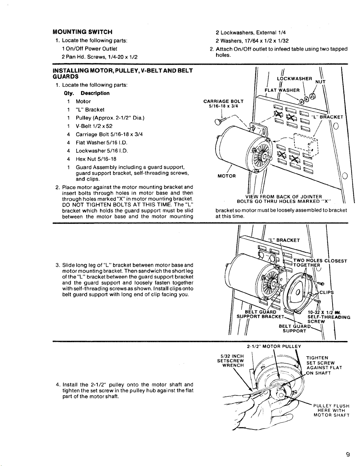
MOUNTING SW|TCH
1. Locate the following parts:
! On/Off Power Outlet
2 Pan Hd. Screws, 1/4-20 x 1/2
IIj!' ILLLjl II JI!l II I
INSTALLING MOTOR, PULLEY, V-BELT AND BELT
GUARDS
1. Locate the following parts:
Qty. Description
1 Motor
1 "L" Bracket
! Pulley (Approx. 2-1/2" Dia.)
1 V-Belt 1/2x52
4 Carriage Bolt 5/16-18 x 3/4
4 Flat Washer5/16 I.D.
4 Lockwasher 5/16 I.D.
4 Hex Nut 5/16-18
1 Guard Assembly including a guard support,
guard support bracket, self-threading screws,
and clips,
2, Place motor against the motor mounting bracket and
insert bolts through holes in motor base and then
through holes marked "X" in motor mounting bracket.
DO NOT TIGHTEN BOLTS AT THIS TIME. The "L"
bracket which holds the guard support must be slid
between the motor base and the motor mounting
2 Lockwashers, External 1/4
2 Washers, 17/64 x 1/2 x 1/32
2. Attach On/Off outlet to infeed table using two tapped
holes.
CARRIAGE BOLT
5/16-18 x 3/4
bracket so motor must be loosely assembled to bracket
at this time.
3. Slide long teg of"L" bracket between motor base and
motor mounting brackeL Then sandwich the short leg
of the"L" bracket between the guard support bracket
and the guard support and loosely fasten together
with self-threading screws as shown. _nstall clips onto
belt guard support with long end of clip facing you.
4. Install the 2-1/2" pulley onto the motor shaft and
tighten the set screw in the pulley hub against the flat
part of the motor shaft.
5/32 INCH
SETSCREW
WRENCH
SUPPORT BRA(
///
2-1/2" MOTOR PULLEY
BRACKET
TWO HOLES CLOSEST
TOGETHER
t0-32 X 112 IN.
SELF-THREADING
BELT GUARD_,_ I_
SUPPORT _'_t
SCREW
TIGHTEN
SET SCREW
AGAINST FLAT
ON SHAFT
_CLIPS
FLUSH
HERE WtTH
MOTOR SHAFT
9

6. P0sition btherend Of V:Belt ontoCutter head p_iiey. ........ :
i :
ii1111111 i i ] i i i ii iiii iiii
7. Visually fin tl
eupbothpueys dan until they areV-Belt
perpendicular to the floor by sliding motor sideways
as needed.
8. Press down hard on motor to put tension on theV-Belt
and tighten the motor mounting bolts at this time.
9. Check guard support before tightening motor support
screws to be sure it is centered around motor shaft and
will not rub against shaft when motor is running.
Tighten screws.
10. Push motor pulley belt guard into position onto guard
support.
11. Plug motor cord into outlet on switch box installed
eadier through hole provided in stand.
12, Fasten cord along front side stiffener using the two
cord clips.
' " " I' ' '' ............ ;............ ..............
INSTALLING SLIDING GUARD :
PARTS NEEDED
i .... ::" ....
Sliding Guard
1 Sliding Guard Knob
1 Sliding Guard Rod
2 Sliding Guard Washers(one side of washer is concave)
.2HeX Hd; Screws 1/4-2Ox !/2"
1:::Positionihe sli;ding guaid !:r0d throughthe opening in
the belt guard asillUstratedl :;......
2: Screw i/2" nut all the way onto long end0f rod..:.
place i/2!' !ockwasher next to nut (as illustrated) ....
3. SCrew the sliding guard rod into the jointer as far as it
wil! go with the short end of rod pointing straight up.
4. Tighten the i/2" nutto hold the rod securely in this
position.
II iiiii .lUll II II IH
OPEN END
..I-MUST BE STRAIGHT IN-LINE
__ AT 90° WITH RELATIONSHIP
_-_--__. TO THE FLOOR
1
[ ........ ! GUARDS REMOVED
,----_V-BELT
/ _=___:__.... _ _ FOR PICTURE CLARITY
MOTOR _i_-_r \
/ / i:'_--_ STRAIGHT LINE
/ / .J _, I UP--DOWN
/ / 9o_'m, \ I
// ( I ',',
: 2 Hex Nuts 1/4-20
......... '1 Rex Nut 1/2 in. - 13
1 Split iockwasher 1/2 in,
2 Ext, tooth Iockwashers
2 10-32 x 1/4 Pan Hd. Screws
I Belt Guard
....... Ill I J IJ
1i2, LOCKWAS_R
!:: BELT
/
1/2" X 13 /o/ SLIDING
__ GUARD
HEX NUT )_/ GUARD ROD
y
PULLEYS AND V-BELT
iiii i iiiii i ii iiiJlll
1/2" HEX NUT
GUARD RO0
5. Attach guard to stand with hex hd. screws and nuts.
Make sure belt does not scrape guard.
BELT
 Loading...