

Craftsman 113.19771, 113.197751 Owner's Manual
Sears
owners
manual
MODEL
NO.
ll3 .19771
SAW ONLY
113.1977 5l
SAW
WITH
LEGS
Seri a
I
Number
Model
and
serial
number
may
be
found
at
the
front
of the
base.
You
should record both
model
and serial
number
in
a
safe
place
for
future
use.
CAUTION:
Read
GENERAL
and
ADDITIONAL
SAFETY
INSTRUCTIONS
carefully
IO-INCH
RADIAL
SAW
o
assemblV
o
operating
o
repair
parts
Sold
by
SEARS, ROEBUCK
AND
CO., Chicago,
lL.
60684 U.S.A.
Part
No.
63784
Pnnrecl in U.S.A
g
en
erol
sofetY
instructions
for
Power
tools
1.
KNOW
YOUR
POWER
TOOL
;i;;J
the
owner's
manual
carefullv'
.
Learn
rts
application
anO
rimltaiioni
as
well
as
the
specif
ic
ootential
hazards
peculiar
to
this
tool'
2.
GROUND
ALL
TOOLS
-
This
tool
is
equipped
with
an
approved
3-conductor
cord
and
'
s-p'ong
gtunding
type
plug
to
fit
the
proper
grounding
tyit'""tpttti9
Th:
st-t:i
conductor
in the
cord
i, tnt
ilou"Ollg
wire'
Never
connect
the
green
wire
to
a
live
terminal'
3.
KEEP
GUARDS
IN
PLACE
inworkingorder'andinproperadiustmentano
align
ment'
4 REMOVE
ADJUSTING
KEYS
"
AND
wRENcHES
Formhabitofcheckingtoseethatkeysandadiusting
wrenches
ar"
r"*o-utd"from
tool
before
turning
tt on'
5.
KEEP
WORK
AREA
CLEAN
,.^:
Cluttered
ttt"
unO
Oenches
invite
.accidents'
Floor
t"r.i
".,
be
slippery
due
to
wax
or
sawclusr'
6.
AVOID
DANGEROUS
ENVIRONMENT
Don't
use
po*"'
tools
in
damp
or
wet
locations
or
expose
them
to
oin'
rc"tp
wor'k
area
well
lighted'
Provide
adequate
surrounding
work
space'
7.
KEEP
CHILDREN
AWAY
A||visitorssnoutdbekeptasafedistancefromworx
dt
co.
8.
MAKE
WORKSHOP
KID'PROOF
-
with
padlocts'
master
switches'
or
by
removtng
starter
keys'
9.
DON'T
FORCE
TOOL
It will
do
the
iob-Ot"*l"O
safer
at
the
rate
for
which
it was
designed'
10.
USE
RIGHT
TOOL
Don't
force
too'
i'-*"hment
to
do
a
iob
it
was
not
designed
for'
11.
WEAR
PROPER
APPAREL
DonotwearIoosec|othing,g|oves,necktiesorjewe|ry
(rings,
wrist
*tttnttl
to
ieicaugnt
in
moving
parts'
Nonslip
toot*tti
it
rgcolnmeld-99
o*ttt
protectrve
hair
covering
tJ
"ontain
long
hair'
Roll
long
sleeves
above
the
elbow'
12.
USE
SAFETY
GOGGLES
(Head Protection)
Wear
Safety
goggles
(must
comply
with
ANSI
287'1)
at
all
times.
lGtvOav
ey-eglasses
only
have-
'impact
resistant
r.nstt,
inty
aie
triOi
safety
glasses'
Also"
use
face
or
dust
mask
ii
cutting
operation
is dusty'
and
ear
13.
SECURE
WORK
Use
clamps
o'
a
uii"
to
hold
work
when-practical'
lt's
safer
than
using
your
hand'
frees
both
hands
to
operare
tool.
14.
DON'T
OVERREACH
'-'
I*o
otoper
footing
and
balance
at
all
times'
15.
MAINTAIN
TOOLS
WITH
CARE
Keep
tools
sna'f
ano
clean
for
best
and
safest
oerformance.
f
orroui
instructions
for
lubricating
and
changing
accessories'
16.
DIscoNNECT
TOOLs
before
servicing;
when
changing
accessories
such
as
blades,
bits,
cutters'
etc'
17.
AVOID
ACCIDENTAL
STARTING
Make
sure
switcn
's
in
"OFF"
position
before
plugging
In.
18.
USE
RECOMMENDED
ACCESSORIES
Consult
the
*tt;t
manual-
for
.
recommended
tJitt.ii.t.
rottow
the
instructions
that
accompanY
the
accessortt''
ir''t
use
of
improper
accessories
may
cause
hazards'
19.
NEVER
STAND
ON
TOOL
Serious
intu'v
toJO
ottur
if
the
tool
is
tipped
or
if
the
"u,ring
tool
is accidentally
contacted'
Do
not
store
materials
above
or
near
the
tool
such
that
it
is
necessary
to stand
on
the
tool
to
reach
them'
20.
CHECK
DAMAGED
PARTS
Before
f
urther
"tJ
tnt
tool'
a
guard
or
other
part
that
is damaged
'nouti
[t
"tt"iu"u
ciected
to
ensure
that
it
will
operate
p,opi'iv
tnd
p"'iottn
i1s
i1te1!eo
t.'""]l:l:
Check
for
atignr;eni
of
moving
parts'
binding
of
movtng
parts,
breaKage
o{
parts'
mounting'.
and
any
otner
conditions
tnt'
'it':tttect
its
operation'
A
guard
or
other
part
tnut
it Outtged
should
be
properly
repaired
or
rePlaced'
2l.DIRECTION
OF
FEED
Feed
work
into
a
blade
or
cutter^aga.rnst
the
direction
oiiotation
o{
the
blade
or
cutter
onry'
22.
NEVER
LEAVE
TOOL
RUNNING
UNATTENDED
Turn
power
oti
Oon't
leave
tool
until
it
comes
to
a
comPlete
stoP'
2
protectors
(Plugs
or
muffs)
operation.
during
extended
Periods
of
addltional
safety
instructions
for
radial
saws
CAUTION:
Always
disconnect
the
power
cord before
removing
the
guard,
changing
the
cutting
tool,
changing
the
set-up
or
making
adjustments.
Shut
off
motor
before
performing
layout
work
on
the saw
table.
WARNING:
DO
NOT
CONNECT
POWER
CORD
UNTTL
THE
FOLLOWING
STEPS
HAVE
BEEN
SATISFACTORI
LY COMPLETED:
l.
Assembly
and
alignment.
ll. Examination
and
operating familiarity
with
ON-OFF
switch,
elevation
control,
yoke
index
and
lock
bevel
index
and lock,
carriage
lock,
guard
clamp
screw,
spreader
and antikickback
device,
and miter
index
and
lock.
I
ll. Review
and
understanding
of all
Safety Instructions
and
Operating Procedures
thru-out
manual.
INSTALLATION
1.
Set carriage
lock
before moving
the saw.
2- Bolt
the saw
to
the
floor
if
it
tends
to slip,
walk, or
slide
during normal
operation.
3. Mount
the
saw
so
the table
is
approximately
39,, above
the
floor.
4. Mount
the saw
so the
arm
slopes
slightly
downward
to
the
rear
so the
carriage
will
not roll forward
due
to
gravity.
5.
lf
you
attach
any
kind
of table
extensions
over
24,,
wide
to
either
end
of the saw,
make sure
you
either
bolt
the saw
to the bench
or floor
as appropriate,
or
support
the outer
end of
the extension from
the bench
or
floor,
as
appropriate.
MI
NI M!ZE
ACCIDENT POTENTIAL
Most
accidents
are
caused
by
FAILURE
TO FOLLOW
setup
and
operating instructions:
(A)
GENERAL
-Avoid
awkward
hand
positions,
where
a sudden slip
could
cause
a hand
to move into
a sawblade
or other
cutting
tool.
Never reach
in
back of or
around
the
cutting
tool with
either
hand
to hold
down the
workpiece,
or
for
any
other reason;
DO
NOT
place
fingers
or hands
in
the
path
of the sawblade.
-
Never saw,
dado, mold.
or rabbet
unless
the
proper
guard
is
installed
and
set up
as
instructed-
_
NOTE
TH E FOLLOWING
DANGER
LABELS
WHICH APPEAR
ON THE
FRONT
OF THE YOKE
AND
GUARD:
OANGER
DAIUGEF: FoP Youn
owil
SAF€TY
READ AI{O
UI{O€RSIAND
OWIIER'S MAI{UAL
AEFONE
OPERATING MACHIr{E.
r.waisaFCfrc6clEs.
a.usE"pusHsncr-roFuihowwonx,
2.
tEEp xdDs
our oF
patB
gF
sltluoE. s. N€vai
iuca
^rouio
rxE
s^wtLioE_
3. XiOW XOf TO IVOIO
.i|CXAACXS,"
6. AIIOW IOOL rO
SrOp OEFonE AbJUSTTNG_
wABtll I luG:
llail,oJi
T*?"'af#9335:iioi.l?
l1'j"u.l'^?,.31
-
lf
any
part
of
this
radial
saw is missing
or should
break,
bend
or
fail
in
any way,
or any
electrical
component
fail
to
perform
properly.
shut
off
power
switch,
remove
cord
from
power
supply
and
replace
damaged,
missing
andlor failed
parts
before
resuming
operation.
_
IF
YOUR
SAW MAKES
AN
UNFAMILIAR
NOISE
O R IF
IT
VIBRATES
EXCESSIVELY
CEASE
OPERATING
IMMEDIATELY
UNTIL
THE
SOURCE
HAS
BEEN
LOCATED
AND THE
PROBLEM
CORRECTED.
-WARNING:
DO
NOT
ALLOW
FAMILIARITY
(GAINED
FROM
FREOUENT
USE
OF
YOUR
SAW) TO
BECOME
COMMONPLACE.
ALWAYS
REMEMBER
THAT A
CARELESS
FRACTION
OF
A SECOND
IS
SUFFICIENT
TO INFLICT
SEVERE
INJURY.
-
Before
starting work,
verify
that no
play
exists
between
the column
& column
support, or
in
the
carriage,
and
that arm.
yoke,
and
bevel
locks,/clamps
are
tight.
-
A large
proportion
of
saw
accidents
is
caused by use
of
the wrong
type
blade,
dull, badly set,
improperly
sharpened
cutting
tools,
by
gum
or
resin
adhering to
cutting
tools,
and by
sawblade
misalignment
out-of-parallel
with
the fence.
Such conditions
can
cause
the
material
to stick,
jam
(stall
the saw)
or
"KICKBACK"
at the
operator.
NEVER ATTEMPT
TO
FREE
A
STALLED
SAW
BLADE WITHOUT
FIRST
TURNING
THE
SAW
"OFF".
If
thE
sawblade
is
stalled
or
jammed,
shut saw
,,OFF,,,
remove
workpiece,
and
check
sawblade
squareness
to
table
surface
and
to
the fence,
and check
for
heel.
Adjust
as
indicated.
-
CAUTION:
DO
NOT
cycle the
motor
switch
,,ON"
and
"OFF"
rapidly,
as
this
might
cause
the
sawblade
to
loosen.
In
the
event
this shoutd
ever
occur,
allow
the
saw
blade
to
come
to
a
complete stop and
re-tighten
the
arbor
nut
normally,
not
excessively.
-
D_o
1ot
leave
a
long
board
unsupported
so
the
spring
of
the
board
causes
it
to shift
on
the table.
provide
proper
support
for
the
workpiece,
based
on
its size
and
the
tyBe
of
operation
to
be
performed.
Hold
the
work firmly
against
the
fence.
-
Never
use
a
length
stop
on
the
free
end or edge of
the
workpiece
whether
crosscutting
or
ripping.
Never
hang
onto
or
touch
the free
enJ
of
woikpiece
when
crosscutting,
or
a free
piece
that
is
cui off while
power
is
"ON"
and/or
the
saw
blade is
rotating.
In
s h o rt,
the
cut-off piece
in
anv
,,thru_sawinq"
operation
must
never
be
conf
ined
-
it must
6e
allowed
to move
laterally.
-
Make
sure
your
fingers
do
not
contact
the
terminals
when installing
or removing
the
plug
to or
from
a
live
power
source.
-
Never
climb
on
the saw,
or
climb
near
the saw when
power
is
"ON".
Never
leave
the
saw
with
power
"ON",
or
before
the
cutting
tool
has
come to
a
complete
stop.
Lock
the
motor
switch
and
pur
away
the key
when
leaving
the
saw.
-
Do not
use
any
blade
or
other
cutting
tool marked
for
an operating
speed
lower
than
345b
RpM. Never
use
a cutting
tool
larger
in
diameter
than
the
diameter
for
which
the
saw
was
designed.
For greatest
safety
and eff iciency
when ripping,
use
the
maximum
diameter
blade
for
which
the
saw
is
designed,
since
under
these
conditions
the spreader
is
nearest
the
blade.
-
Never
turn
your
saw
"ON"
before
clearing
the table
or
work surface
of
all
objects
(tools,
scraps
of wood,
etc.)
except
the
workpiece
and related feed
or
support
devices for
the operation
planned.
-
DO NOT
perform
layout.
assembly.
or
setup
work
on
the
table
while
the cutting
tool is rotating.
-Never
perform
any
operation
"FREE
HAND,'. This
term means feeding
the sawblade
into
the workpiece
or
feeding
the
workpiece
into
the
sawblade
or other
cutting
tool
without
using
the
fence
or some
other
device
which
prevents
rotation
or
twistinq
of
the
workpiece
during
the operation.
Never
,,Rti,,
in
the
crosscut
position.
Never
make
a miter
cut with
the
arm
in
the
90o crosscut
position.
*
Never
lower
a
revolving
cutting
tool
into
the
table
or
a workpiece
without first
locking
the
Carriage
Lock
Knob.
Release
the knob
only
after
grasping
the
yoke
Handle.
Otherwise
the cutting
tool may
grab
the
workpiece
and
be
propelled
toward
you.
-
The
sawblade,
dado, or
other cutting
tool must
be
ro ^vorD
I
liJuiY
oo
NO' FECD
]
]
uet:nrt
]
I
riro
I
,
currttc
i
I
TOO!
rnor
I
rHts
Eio
;
i
I
I
additional
safety
instructions
for
radial
saws
removed from
the
saw arbor
before using
the
accessory shaft
(rear
end of the
saw motor). NEVER
operate the
saw
with cutting
tools
(including
sanding
accessories) installed on both ends of the
saw
arbor.
(B)
RIPPING
'l
.
Never
apply
the
feed force
to
the
section
of the
workpiece
that will become the
cut-off
(free)
piece.
Feed
force
when
ripping
must
always
be applied
between
the
saw
blade and
the
fence
.
. . use
a
"PUSH
STICK"
(see
pg.
261
for
narrow or short
worK.
Whenever
possible,
use
the
in-rip
position
-
this
provides
minimum
obstruction
for
feeding
by hand
or
push
stick
as appropriate.
Do not release
the workpiece
before
operation
is
complete
-
push
the workpiece
all
the way
past
the
rear
(outfeed
or exit)
of
the sawblade.
Make
sure
by trial
before
starting
the
cut that the
antikickback
pawls
will stop
a kickback
once
it
has
started.
Keep
points
of
pawls
SHARPI
Use
a
push
stick
when
ripping
short
(under
12
inches)
or
narrow
(under
6
inches
wide)
workpieces.
CAUTION:
Never reposition
the Guard
or
antikickback
with
power
"ON".
A
"KICKBACK"
occurs
during a
rip-type
operation
when
a
part
or
all
of
the workpiece is
thrown back
violently
toward
the operator. lt
can
occur when
the
workpiece
closes
in
on
the
rear
(outfeed
side)
of
the
sawblade
(pinching),
binds between the
fence
and the
sawblade
(heel),
or is
grabbed
by the
sawblade
teeth
(wrong-way
feed)
at
the
outfeed
side.
"PlNCHlNG"
is
generally
avoided
by
utilization
of the
spreader,
and a sharp sawblade
of
the correct
type for
the
workpiece
being cut.
' 'H
E
E L" can
be avoided
by maintaining
the
sawblade
exactly
parallel
to
the
fence.
Grabbing
by
the
sawblade
teeth can
be caused by heel
or
by
feeding
from
the wrong
direction
(see
"DANGER"
wa
rning
on
guard)
it
can
be avoided
by
maintaining
parallelism
of sawblade
to
fence,
feeding
into
the sawblade
from
the nose of
the
guard
only, and
by
positioning
the
spreader
and
antikickback
property,
and keeping
the
workpiece
down on
the table
and against the
fence.
Position
the
nose
of
the
guard
to
just
clear
the
workpiece,
and
position/ad
just
the antikickback
and spreader
devices as instructed.
NEVER
cut more
than one
piece
at a time
by
stacking
workpieces vertical
ly.
10.
NEVER
feed
a
workpiece
thru the
saw with
another
piece
(butting
second
piece
against trailing edge of
piece
being cut), even if
of the
same
thickness.
Feed
each workpiece individually
thru the sawblade,
and
completely beyong
the sawblade,
before
ripping
the
next workpiece.
Use
push
stick
if
the
rip
cut
is less
than
6" wide.
1 1 .
DO NOT
pull
the workpiece
th ru
the sawblade
-
position your
bod1, at
the
nose
(in-feed)
side
of
the
guard:
start
and
complete
the
cut
from
that
same
side. This
will
require
added table
support
for
long
pieces.
12. Plastic
and
composition
(like
hardboard)
materials
may
be cut
on
your
saw.
However, since
these are
usually
quite
hard and
slippery.
the antikickback
pawls
may not stop
a
kickback.
Therefore,
rip
with
the
finished
side
down
(next
to
the table)
and
be especially
attentive
to
following
proper
set-up
and
cutting
procedures.
Do not stand,
or
permit
anyone else to
stand, in line
with a
potential
kickback.
13. When
sawing 1/4"
or thinner
materials,
follow
all
normal ripping
procedures
except
set
sawblade into
table
top at
least 1/8".
DO NOT
let
go
of or
stop
feeding
the workpiece between the blade
and
fence
until
you
have
pushed
it completely
past
the
antikickback
pawls.
Otherwise the workpiece
could
get
into
the back of the sawblade
and be thrown
violently from
the
saw
in
the direction opposite
to
the
feed
direction.
This
is
the
same
action
that
would
occur if the instructions
of
the
DANGER
warning
on
the
guard
is
aborted. Do not stand,
or
permit
anyone else to stand,
in
line with
the
path
of
a
workpiece
that
may
be thrown from
the
saw
in
this manner.
14.
Position
the
saw
so
neither
you,
a
helper,
or
a casual
observer is
forced
to
stand
in
line with
the
sawblade.
15.
Use extra
care when ripping
wood that has a twisted
grain
or
is
twisted or bowed - it may rock
on
the
table and/or
pinch
the
sawblade.
(C)CROSSCUTTING
1. ALWAYS
RETURN THE
CABRIAGE
TO THE
FULL
REARWARD POSITION
AT CONCLUSION
OF EACH
CROSSCUT
TYPE
OPERATION.
Never
remove
your
hand from
the
Yoke
Handle
unless the
carriage is
in
this
position.
Otherwise the cutting
tool
may
climb up
on the
workpiece
and
be
propelled
toward
you.
2.
Place guard
in horizontal
position
and adjust
antikickback
pawls
to
just
clear
the top of the
fence
or workpiece, whichever is
higher.
3. NEVER
gang
crosscut - lining
up more than one
workpiece in front
of
the
fence - stacked vertically,
or
horizontally
outward
on
the table - and
then
pulling
saw
thru:
the blade could
pick
up one or
more
pieces
and
cause a binding or loss
of control
and
possible
injury.'
4. Do
not
position
the
Arm
so
the
operation
you
are
perf
orming
permits
the cutting
tool to
extend
beyond
the edges of
the
Table.
(D)
ACCESSORTES
1. Use only recommended
accessories as
listed
on
page
34.
Never
operate
this saw
when equipped with a
dado
head or molding
head unless
the
molding
head
guard
is installed
-
see
listing
of recommended
accessories. The
only
exception
is
when
"top-side"
dadoing
or molding,
when the sawblade
guard
must
be used.
See
detailed
instructions
that accompany
the
dado
head, molding head, and
molding
head
guard.
The
use
of abrasive
or cut-off
wheels, or
wire
wheels,
can
be
dangerous and
is not
recommended.
(Abrasive
or cut-off wheels
are
used
to
saw
many
different materials including
metals,
stone,
and
glass.
)
Drill
Chuck:
Do
not install
or use
any
twist
drill
f
arger
than 1|2-inch in
dia.,
or
ionger
than 7 incnes
in
length
or extending
more than 6 inches
beyond
the chuck
jaws.
Do
not
install
or
use
any reduced
shank
drill except of the
spade
type
(1
inch
dia. or
smaller).
"Use
for
drilling
WOOD
and
PLASTIC
onlv."
2.
?
4.
6.
8.
9.
2.
4.
WEAR
YOUR
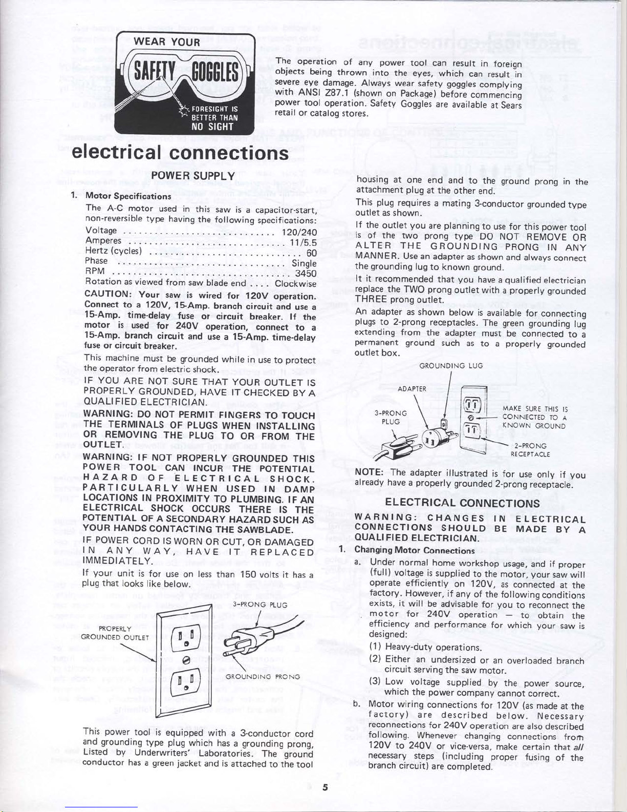
The
operation
of any
power
tool
can result
in
foreign
objects
being
thrown
into
the
eyes,
which
can
result
in
se.vgre
9y9
damage.
Always
wear
safety goggles
complying
with
ANSI
287.1
(shown
on
packaget
OJtore
commencing
power
tool
operation.
Safety
Goggles are
available
at
Seari
retail
or
catalog
stores.
GROUNDING
LUG
ADAPTER
I
3-PRONG
PLUG
MAKE
SURE
THIS
tS
CONNECTED
TO
A
KNOWN
GROUND
RECE
PTACLE
-
-i--'-2-PR.NG
This
power
tool is
equipped
with
a
3-conductor
cord
and grounding
type
plug
which
has a grounding prong,
Listed
by
Underwriters'
Laboratories.
The - ground
conductor
has a green
jacket
and is
attached
to the
tool
NOTE:
The adapter
illustrated
is
for
use
only if
you
already
have
a
properly
grounded
2-prong
receptacle.
ELECTRICAL
CONNECTIONS
WARNING:
CHANGES
tN
ELECTRTCAL
CONNECTIONS
SHOULD
BE
MADE
BY
A
OUALI
FI
ED
ELECTRICIAN.
Changing
Motor
Connections
a.
Under
normal
home
workshop
usage,
and if
proper
(full)
vell3gq
is
supplied
to
the motor,
your
saw
will
operate
efficiently
on
120V,
as connected
at the
factory.
However,
if
any
of the following
conditions
exists,
it
will be
advisable
for
you
to reconnect
the
.
motor
for
24OY
operation
-
to
obtain
the
efficiency
and
performance
for
which
your
saw
is
designed:
(1
)
Heavy-duty
operations.
(2)
Either
an
undersized
or an
overloaded
branch
circuit
serving
the
saw
motor.
(3)
Low
voltage
supplied
by
the
power
source,
which
the
power
company
cannot
correct.
b.
Motor
wiring
connections
for
120V
(as
made
at the
factory)
are described
below.
Necessary
reconnections
for
240V
operation
are
also described
following.
Whenever
changing
connections
frorh
120V
to 24OY
or vice-versa,
make
certain
thatall
necessary
steps
(including
proper
fusing
of the
branch
circuit)
are
completed.
electrical
connections
POWER
SUPPLY
1.
Motorspecifications
The
A-C motor
used in
this
saw is
a capacitor-start.
non-reversible
type
having
the following
specifications:
Voftage
eO/24O
Amperes
11l1.s
Hertz(cycles)
....
.......60
Phase
. .
Sinqle
RPM
.
...
3460
Rotation
as viewed
from
saw
blade
end . .
. . Clockwise
CAUTION:
Your
saw
is
wired
for 12Ov
operation.
Connect
to
a 120V,
l$Amp.
branch
circuit
and
use
a
15-Amp.
time-delay
fuse
or
circuit
breaker.
lf
the
motor
is
used
tor
24OY
operation,
connect
to
a
15-Amp.
branch
circuit
and
use
a 1S-Amp.
time-delay
fuse
or circuit
breaker.
This
machine
must
be
grounded
while
in
use to
protect
the
operator
from
electric
shock.
IF
YOU
ARE
NOT
SURE
THAT
YOUR
OUTLET IS
PROPERLY
GROUNDED,
HAVE
IT
CHECKED
BY
A
OUALI FI
ED
ELECTRICIAN.
WARNING:
DO
NOT PERMTT
FTNGERS
TO TOUCH
THE
TERMINALS
OF PLUGS
WHEN INSTALLING
OR
REMOVING
THE PLUG
TO
OR
FROM THE
OUTLET.
WARNING:
IF
NOT
PROPERLY
GROUNDED THIS
POWER
TOOL
CAN INCUR
THE POTENTIAL
HAZARD
OF
ELECTRICAL
SHOCK.
PARTICU
LAR
LY
WHEN
USED
IN
DAMP
LOCATIONS
IN
PROXIMITY
TO PLUMBING.
IF
AN
ELECTRICAL
SHOCK
OCCURS
THERE
IS
THE
POTENTIAL
OF
A
SECONDARY
HAZARD
SUCH
AS
YOUR
HANDS
CONTACTING
THE
SAWBLADE.
IF POWER
CORD
IS
WORN
OR CUT,
OR DAMAGED
IN
ANY
WAY,
HAVE
IT
REPLACED
I.
IMMEDIATELY.
lf
your
unit is
for
use on
less
than 150
volts it
has
a
plug
that
looks
like
below.
PROPERLY
GROUNDED
OUILET
housing
at
one
end and
to
the ground
prong
in
the
attachment
plug
at the
other
end.
This
plug
requires
a mating
3-conductor
grounded
type
outlet as
shown.
lf
the
outlet
you
are
planning
to
use for
this
power
tool
is
of the two
prong
type
DO
NOT REMOVE
OR
ALTER
THE
GROUNDING
PRONG
IN
ANY
MANNER.
Use an
adapter
as shown
and
always connecr
the
grounding
lug
to known ground.
It
it recommended
that
you
have
a
qualified
electrician
rypF9e
the
TWO
prong
outlet with
a
properly
grounded
THREE
prong
outlet.
An adapter
as shown
below
is
available
for
connectinq
plugs
to 2-prong
receptacles.
The green
grounding
lu!
extending
from
the adapter
must
be
connected
to
i
permanent
ground
such
as
to a
properly
grounded
outlet
box.
ff-r]t
tot
o
fil
\"'
3-PRONG
PLUG
GROUNDING
PRONG

IOR
UsE
ON
r 20v I
240v
5unc:
rero
oru
EROWN
LEAD
ON
o
18
5l
electrical
connections
Connections
for
120V
A'C'
a.-
Ratou"
nameplate
cover
from
motor
to
expose
terminal
boarcl'
u.
ii.
*ir.,
inside
of
the
motor
must
be
connected
as
shown:
(1)
The
orange-colored
wire
on
number
6
terminal'
(2)
The
b'o*n-coto"d
wire
on
number
5
terminal'
c.Usethel20Vpower.cordp|ugfurnishedwithyour
saw'
Connections
for
240V
A'C'
a.
The
wires
inside
the
motor
terminal
box
must
be
connected
as
follows:
(1)
The
orange-colored
wire
on
number
8
terminal'
(2)
The
brown-colored
wire
on
number
7
terminal'
b.
Replace
the
120V
power-cord
plug
with
a
(3-blade)
240V
plug,
"onn"Jting'tnt
po*ti-"ord..white
and
black
leads,
"'ptiiiuJrv'
to
the
two
"hot"
plug
blades
-
,no
"onnJttlnj
irtt
po*tt-cord
grounding
wire
to
the
Plug
ground
Prong'
d.
Make
certain
the
receptacle
is
co-nnected
to a
240V
A-c
power
t'ppl;;;;Gh
a
2a0v
!1nctr
circuit
having
at
least
t,i'S-ttp'
itpacitv'
a1d-1;'otected
bv
a
1S-amp'
trme-oelay
fuse
or
circuit
breaker'
MOTOR
SAFETY
PROTECTION
NOTE:
This
motor
should
be
blown
out'
or
"vacuumed"'
freouently
to
prevent
;;ilil
interference
with
normal
motor
ventilation.
Your
saw
motor
is
equipped , yitl^i.manual-reset'
thermal
-overl
oad
protecto-rTtli
lntO
tt
99:l llt
power-l
i ne
circuit
when
the
rnoror
a'.'.p.raiure
exceeds
a
safe
value'
I
2.
3.
1.
lf
the
protector
opens
the
line
and'stops
the
saw
motor'
immediately
p""
'ittt'-iaw
switch
to
the
"OFF"
p"titf
"",
and
allow
the
motor
to
cool'
2.Aftercoolingtoasafeoperatingtemperature,the
overload
protector
"tn
U"
"iot"A
manually
by
pushing
in
the
red
button
Jn
ar,.
,op
of
the
motor.
lf the
red
button
will
not
tntf
into
place
immediately'
the
motor
is
still
too
hot
and
Lutt
U"
allowed-t^o
cool
for
a
while
lonqer.
In
some
".r.,
aii,
,ry
take20-30
minutes.
(An
r"ril[:'I,
"ii"[
*irr
l"oicate
protector
is closed')
3.
As
soon
as
the
red
button
will
snap
into
running
position.
the
tt*-
tty
-Ue
start-ed^'and
operated
normally,
by
pulling
o"'tft"
saw
switch
to the
"ON"
position
'
4.
Frequent
opening
of
fuses
or
circuit
lrealers
may
result
if motor
is
overlo]deJ'
or
if
the
motor
circuit
is
fused
differently
tr.ot
-""ot-endations'
Overloading
can
occur
if
you
feed
;itpiJtv
or
if
Your
sa;v
is
misaligned
so
that
the
blade
heels'
Do
not
use
.u
1-t-t-,:,f^:t"tttt
"apicitv
without
consulting
a
qualified
electrlclan'
5.
Although
the
motor
is
designed
for
operation
on
the
voltage
anO
t'equl-ncv
tpu"iiitO
9n,
t::ot
nameplate'
normal
toads
wiri
Ue
handled
sa.fely
on
voltages
not
more
than
tO'U"
atove
or
below
the
nameplate
voltage'
Heavy
loads,
no*u"tt'
require
.lltl
,u-oltust
at
motor
terminals
.q"r'
trtl-*itage'specified
on
nameplate'
6.Mostmotortroub|esmaybe.tracedtolooseor
incorrect
tonntii'ont'
overloading'
reduced
input
voltage
(such
as
tt"ritiit
*ites
in
thJ
supplv
circuit)
or
to
an
overly-'""n'-t"ooit'-liicuit'
,Always
check
the
connections,
tnt
ioJ
tnd
the
supply.
circuit'
whenever
the
motor
tairt
il""p#ott.ttliiltclorilv'
Check
wire
iit".
.nO
lengths
with
the
table
followrng'
WIRE
SIZES
The
use
of
any
extension
cord-will
cause
some
loss
of
power.
To
t""p
ii"it-'io
i
minimum
and
to
prevent
6
GROUNDING
BLADE
15
LONGEST
OF
3
BLADES
NO
ADAPTER
IS
AVAILABLE
FOR
THIS
TYPE
PLUG
PROTECTOR
(RED BUTTON)
FOR USE
ON
I 20V
240V
ORANGE
LEAD
ON
6
8
gRowl
rtlo
ON
5
7
24OV
PLUG
&
RECEPTACLE
c.
Plug
your saw
into
a24OY '
3-blade
receptacle'
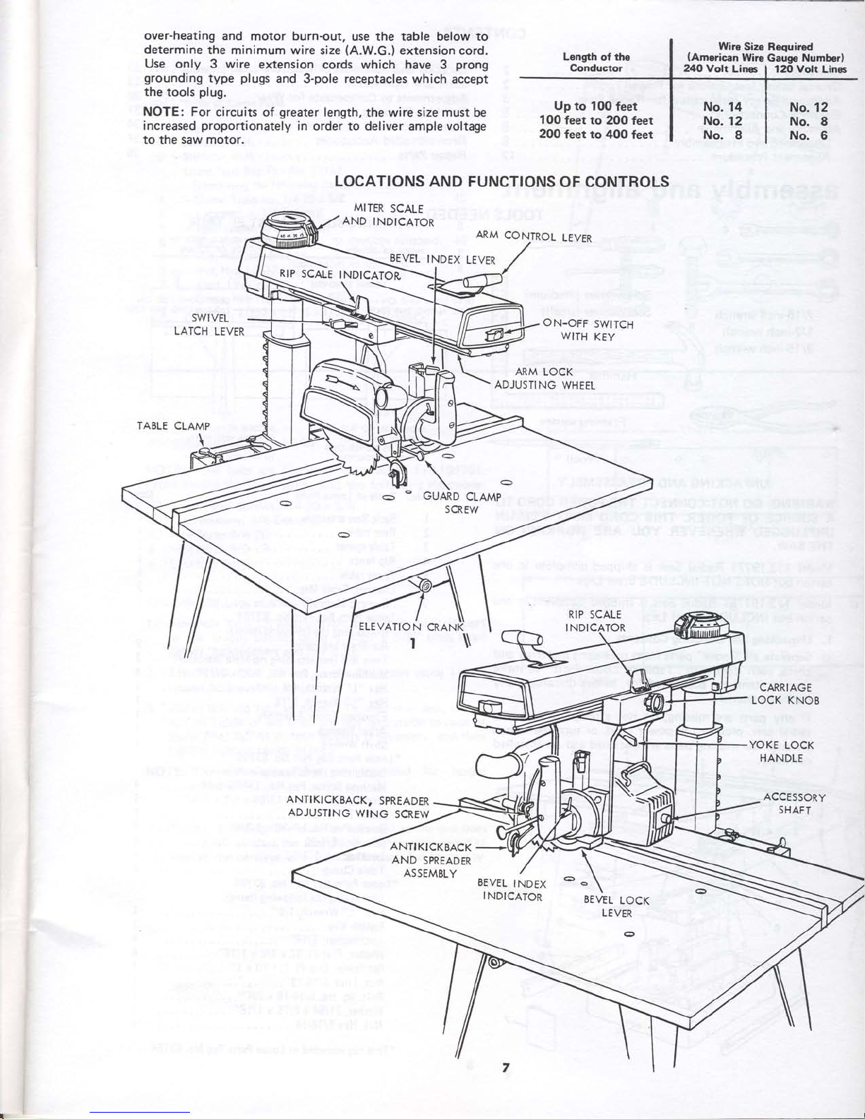
over-heating
and motor burn-out,
use the table below to
determine
the minimum
wire size
(A.W.G.)
extension
cord.
Use
only 3 wire
extension
cords which have
3
prong
grounding
type
plugs
and
3-pole
receptacles which
accept
the
tools
plug.
NOTE: For circuits
of
greater
length,
the wire
size must
be
increased
proportionately
in
order to
deliver
ample
voltage
to the
saw
motor.
SWIVEL
LATCH
LEVER
LOCATIONS
AND FUNCTIONS
OF CONTROLS
MITER
SCALE
AND
INDIC,ATOR
ARM
CON-TROL
LEVER
BEVEL
INDEX
LEVER
ON-OFF
SWITCH
WITH
KEY
ARM
LOCK
ADJUSTING
WHEEL
RIP
SCALE
INDICATOR
TABLE
CLAMP
CARRIAGE
LOCK
KNOB
YOKE
LOCK
HANDLE
ANTIKICKBACK,
SPREADER
ADJU5TING
W]NG
SCREW
ACCESSORY
SHAFT
.
Wire
Size Required
lAmerican Wire
Gauge
Numberl
240
Volt
Line
|
120
Volt
Lines
Up to
100
feet
1 00
feet to
200 feet
200
feet to 400
feet
RIP
SCALE
INDtCATOi
ANTIKICKEACK
AND
SPREADER
ASSEMBLY
EEVEL
INDEX
INDICATOR
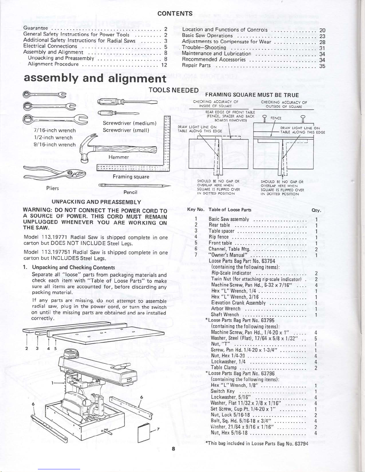
CONTENTS
Guarantee
......2
General
Safety
Instructions
for
Power
Tools
.........
2
Additional
Safety
Instructions
for
Radial
Saws .......
3
ElectricalConnections
........5
AssemblyandAlignment
....
........8
UnpackingandPreassembly...
.:....
g
AlignmentProcedure
.......12
s\_,!l!j:l,-
\d-=$l-]
7/
1
6-inch wrench
'l
/Z-inch
wrench
9/1
6-inch
vvrench
Screwdriver
(medium)
Screwdriver
(small)
Framing
square
:.-
Pencil
UNPACKING
AND PREASSEMBLY
WARNING:
DO NOT
CONNECT
THE
POWER
CORDTO
A
SOURCE
OF
POWER.
THIS
CORD
MUST
REMAIN
UNPLUGGED
WHENEVER
YOU
ARE
WORKING
ON
THE
SAW.
Model
113.19771
Radial
Saw
is
shipped
complete in one
carton but DOES
NOT
INCLUDE
Steel
Legs.
Model 1 13.197751
Radial
Saw is shipped
complete in
one
carton but
INCLUDES
Steel
Legs.
1.
Unpacking
and Checking
Contents
Separate
all
"loose"
parts
from packaging
materials
and
check
each item
with
"Table
of Loose Parts" to
make
sure
all
items
are accounted for,
before
discarding
any
packing
material.
lf
any
parts
are missing,
do not
attempt
to
assemble
radial
saw,
plug
in
the
power
cord,
or turn
the
switch
on until the missing
parts
are obtained
and are installed
correctlv.
Location
and
Functions
of
Controls
Basic
Saw Operations
Adjustments
to Conipensate
for
Wear
Trouble-Shooting
Maintenance
and Lubrication
. .
Recommended
Accessories
Repair
Parts
20
23
28
31
34
34
?tr
assembly
@::=€
@F-=-S
and
alignment
TooLs
NEEDED
FRAMTNG
souARE
MUsr BE
TRUE
CH€CKING ACCURACY
OF
INSIDE
OF SQUARE
CHECKING
ACCURACY
OF
OUTSIDE
OF
SQUARE
DRAW
TABLE
REAR
EDGE OF FRONT
TABLE
(FENCE,
SPACER
AND BACK
BOARDS
REMOVED)
SHOULD 8E NO
GAP OR
OVERLAP
HER€ WHEN
SQUARE IS FLIPPED
OVER
IN
DOTTED
POSITION
Key No.
Table
of Loose Parts
DRAW
LIGHT
LINE ON
TABL€
ALONG
THIS
EDGE
>
Pliers
SHOULD
BE NO
GAP OR
OVERLAP
HERE
WHEN
SAUARE
IS
FLIPPED
OVER
IN
DOTTEO POSITION
I
I
?
4
E
o
7
Basic
Saw assembly
Rear
table
Table
spacer
Rip fence
Front
table
Channel,
Table
Mtg.
"Owner's
Manual"
Loose Parts
Bag
Part
No. 63794
(containing
the
f
ollowing
items):
Rip-Scale
Indicator
Twin
Nut
(for
attaching rip-scale
indicator)
Machine
Screw,
Pan
Hd.,
6-32
x7116"
Hex
"
1"
Wrench, I
/4
Hex
"1"
Wrench,
3/1 6
Elevation
CrankAssembly
....
Arbor
Wrench
Shaft
Wrench
*
Loose
Parts
Bag Part
No. 63795
{containing the
following
items):
Machine
Screw,
Pan
Hd.,'l
l4-20
x 1"
Washer, Steel
(Flat),
17
164
x 518
x 1132" .
.
Nut,
"T"
Screw,
Pan
Hd. 114-20
x 1-314"
Nut, Hex
114-20
.
Lockwasher.114
...
Table
Clamp
*Loose
Parts
Bag
Part
No. 63796
(containing
the
following
items):
Hex
"1"
Wrench,
118"
. .
Switch Key
Lockwasher,5/16"
Washer, Flat
11/32
x718x1116"
Set
Screw, Cup
Pt.
1
/4-20
x 1" - -
Nut,
Lock 5/16-18
Bolt,
Sq. Hd.
5/16-18 x 314"
.
rYasher.21lE4
x
9i16 x 1/16"
Nut, Hex
5/16-18
*This
bag
included
in Loose Parts
Bag
No.
63794
€lty.
1
1
+
1
2
2
L
z
4
5
I
I
A
2
LIGHT
LINE ON
ALONG
THIS EDGE
(?,
LI
I
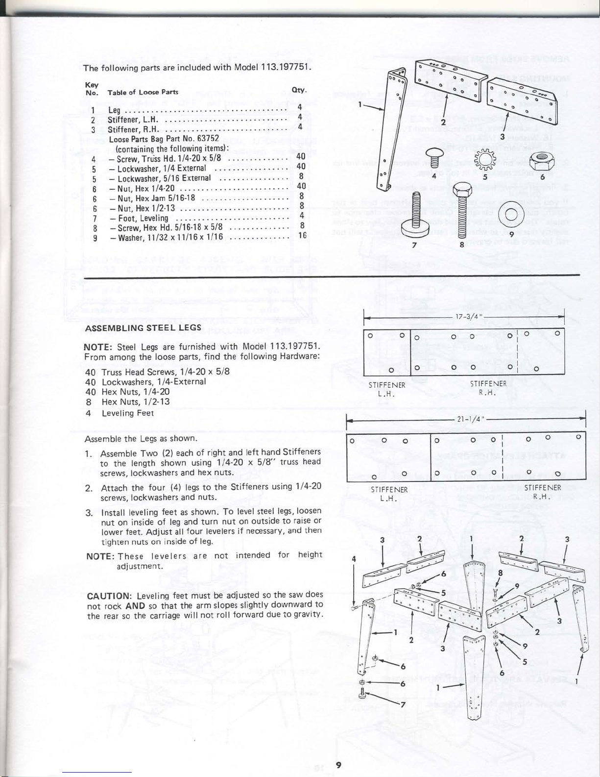
The
fof f owing
parts
are
included
with
Model
113'197751 .
,$a
Ue
g
7
Key
No.
'|
2
3
Table
of
Loose
Parts
Leg
...
Stiffener,
L.H.
..
Stiffener,
R.H.
. .
Loose
Parts
Bag
Part no. o'si'S'Z'
(containing
the
following items):
-
Screw.
Truis
Hd.
114'20
x5l8
- . .
-
Lockwasher,
l/4
External
-
Lockwasher.
5/16
External
-
Nut,
Hex 114'20
.
-
Nut,
HexJam
5/16{8
-
Nut,
Hex 112-13
.
-
Foot. Leveling
-
Screw,
Hex
Hd. 5/16-18
x 5/8
.
-
Washer.
11132
x l1/16
x 1/16
. .
oty.
4
4
4
4
5
5
6
6
6
7
8
I
40
40
I
40
8
8
4
8
't6
s}{"
a\_-/J
</t'u
5
@
6
a
\E{
FJ
g
v
8
r-))
9
40
40
40
8
4
ASSEMBLING
STEEL
LEGS
NOTE:
Steel
Legs are
furnished
with
Model
113.197751 .
From
among the
loose
parts,
find
the
following
Hardware:
Truss
Head Screws,
114-20x5/8
Lockwashers, 1 /4-External
Hex
Nuts, 1/4-2O
Hex
Nuts, 1/2-13
Leveling
Feet
Assemble
the
Legs
as shown.
1.
Assemble
Two
(2)
each
of
right
and
left
hand Stiffeners
to
the
length
shown
using 1/4-20
x
518"
truss
head
screws,
lockwashers
and
hex nuts.
2.
Attach
the
four
{4)
legs to the Stiffeners
using 1/4-20
screws,
lockwashers
and
nuts.
3.
Install leveling
feet
as
shown.
To
level steel
legs,
loosen
nut on
inside
of leg and
turn
nut on
outside to
raise
or
lower
feet.
Adjust
all
four
levelers
if
necessary,
and
then
tighten
nuts
on inside
of
leg.
NOTE:
These
levelers
are
not
intended
for
height
adiustment.
CAUTION: Leveling
feet must be adjusted
so
the
saw
does
not rock AND so
that
the arm
slopes
slightly
downward
to
the
rear so the
carriage
will
not
roll
forward due to
gravity.
o
o
lo
olo
""1:
" "
o
STIFFENER
L.H.
STI
FFE NER
R.H.
STI
FFE NER
e.-5
&\,
9
21-1/4"+
STIFF E NER
tlJ
o
o
o
lo
o
o
ooo
o
o
oo
o
o
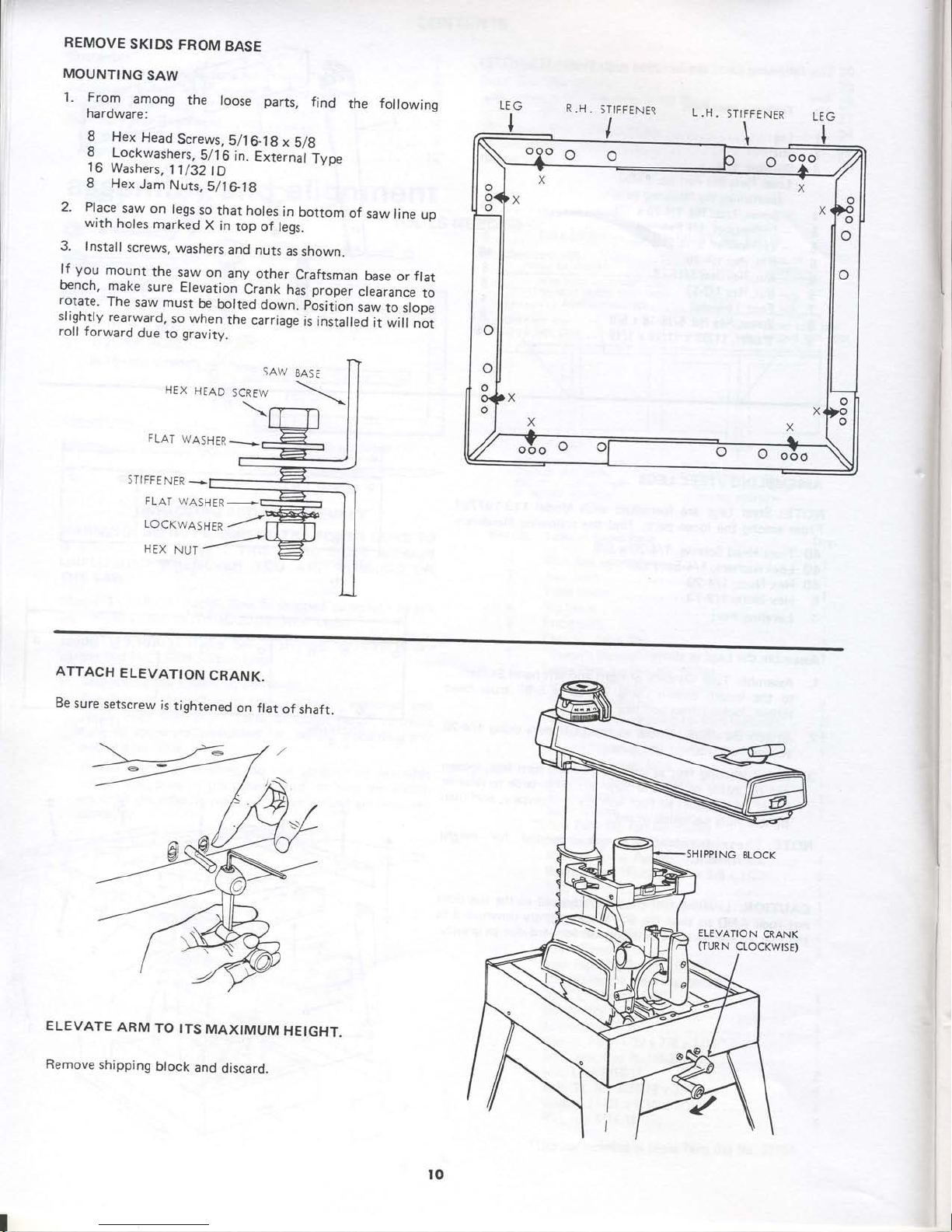
REMOVE
SKTDS
FROM
BASE
MOUNTING
SAW
1.
.FroT
among
the
loose parts,
find
the
following
hardware:
8
Hex
Head
Screws,5/16_1g
x
5/g
8^
.Lockwashers,
5/.l6
in.
exierna'tlype
16
Washers,
11/32tD
8 Hex
Jam
Nuts,5/lGlg
2. Place
saw
on
legs
so
that holes
in
bottom
of
saw line
up
with
holes
marked
X
in
top
of
legs.
3. lnstall
screws,
washers
and nuts
as
shown.
lf
you
mount
the
saw
on
any
other
Craftsman
base
or
flat
bench,
make
sure
Elevation
Crank
has
propei
clearance
to
rotate.
The
saw
must
be
bolted
down.
position
saw
to slope
sligh-tly
rearward,
so when
the
carriage
is
instailed
it
wiil
not
roll
forward
due
to
gravity.
R.H.
STIFFENER
SAW
BASE
HEX
HEAD
SCREW
FLAT
WASHER-
STIFFE
NER
FLAT
WASHER
loc<wassen
/
HEX
NUT
ATTACH
ELEVATION
CRANK.
Be
sure
setscrew
is
tightened
on
flat
of shaft.
ELEVATE
ARM
TO
ITS
MAXIMUM
HEIGHT.
Remove
shipping
block
and
discard.
ro
assembly
and alignment
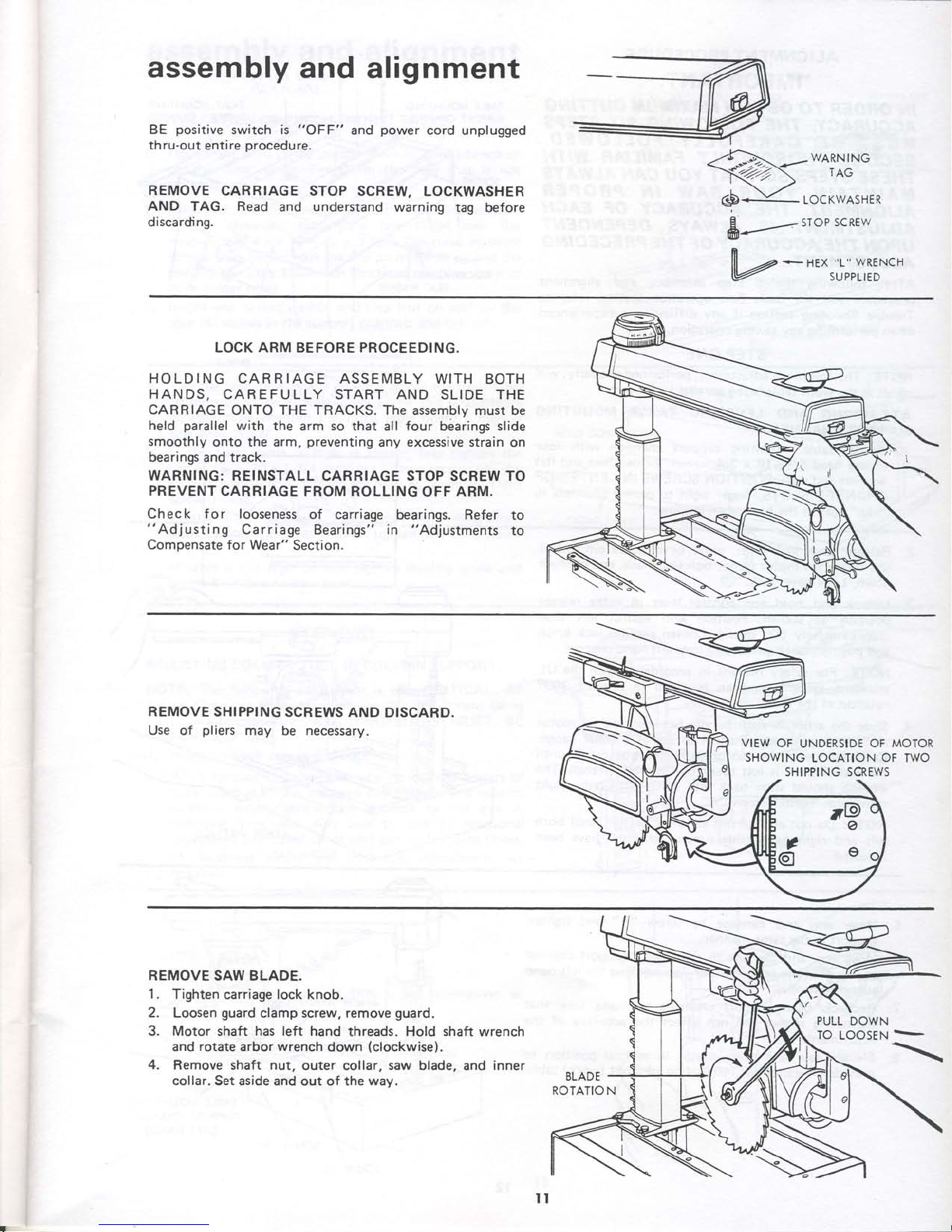
BE
positive
switch is
"OFF"
and
power
cord unplugged
thru-out
entire
procedure.
REMOVE
CARRIAGE STOP SCREW,
LOCKWASHER
AND TAG. Read
and
understand
warning tag
before
discarding.
@t*ofi:fo
6p
-
LocKwAsHER
&
,
sToP scREw
V*n'*rrt
rillto*tt
LOCK
ARM
BEFORE PROCEEDING.
HOLDING
CARRIAGE ASSEMBLY WITH
BOTH
HANDS,
CAREFULLY START AND
SLIDE
THE
CARRIAGE
ONTO THE TRACKS. The assembly
must
be
held
parallel
with
the arm so that
all
four
bearings
slide
smoothly
onto the arm,
preventing
any
excessive
strain on
bearings
and
track.
WARNING:
REINSTALL CARRIAGE STOP SCREW TO
PREVENT
CARRIAGE
FROM ROLLING
OFF
ARM.
Check for looseness
of
carriage
bearings.
Refer
to
"Adjusting
Carriage Bearings" in
"Adjustments
to
Compensate
for Wear"
Section.
REMOVE SHIPPING
SCREWS
AND
DISCARD.
Use of
pliers
may
be
necessary.
VIEW
OF
UNDERSIDE
OF MOTOR
SHOWING
LOCATION OF TWO
SHIPPING SCREWS
REMOVE SAW BLADE.
1.
Tighten
carriage
lock
knob.
2.
Loosen
guard
clamp screw, remove
guard.
3. Motor shaft has left hand
threads. Hold shaft wrench
and
rotate
arbor
wrench
down
(clockwise).
4,
Remove shaft nut,
outer collar, saw blade,
and
inner
collar. Set aside
and out of the
way.
PULL
DOWN
TO
LOOSEN
ALIGNMENT
PROCEDURE
IMPORTANT:
IN ORDER
TO
OBTAIN
MAX'MUM
CUTT'NG
ACCURACY,
THE FOLLOWI'VG
S'X
STEPS
MUST
BE
CAREFULLY
FOLLOWED.
BECOME
THOROUGHLY
FAMILIAR
WITH
THESE
STEPS
SO
THAT
YOU CAN
ALWAYS
MAINTAIN
YOUR
SAW
'N
PROPER
ALIGNMENT.
THE
ACCIJRACY
OF
EACH
ADJUSTMENT
'S
ALWAYS
DEPENDENT
UPON
THE
ACCIJRACY
OF
THE
PRECEDING
ADJUSTMENT.
After
following the
6 step
assembly
and alignment
procedure
and the Basic
Saw operation
section
refer to
Trouble Shooting
section
if any difficulty
is
experienced
when
performing
any
sawing operation.
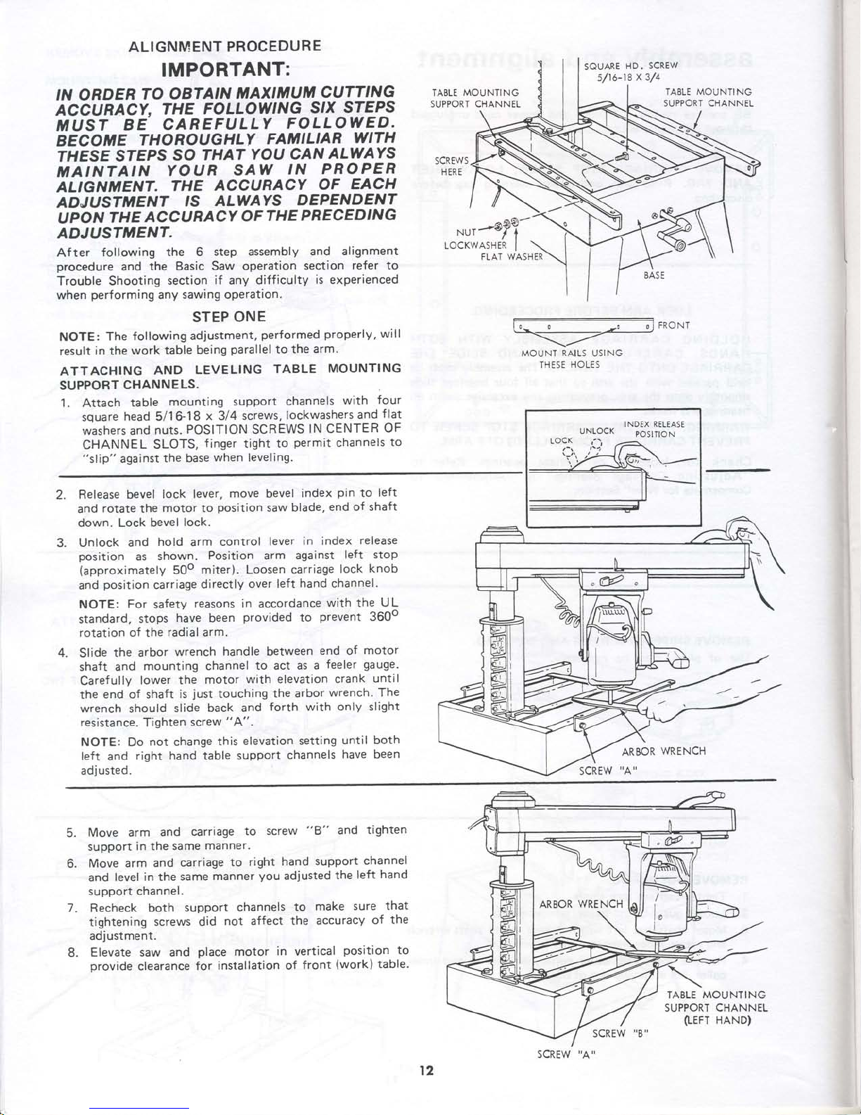
STEP
ONE
NOTE:
The
following
adjustment,
performed
properly,
will
result
in
the
work
table
being
parallel
to
the arm.
ATTACHING
AND
LEVELING
TABLE
MOUNTING
SUPPORT
CHANNELS.
1
. Attach
table
mounting
support
channels
with
four
souare
head
5/16-18
x 3/4 screws,
lockwashers
and
flat
washers and
nuts.
POSITION SCREWS
lN CENTER
OF
CHANNEL
SLOTS,
f
inger tight
to
permit
channels
to
"slip"
against
the base
when leveling.
FRO
NT
MOUNT RAILS
U5ING
I NI)E hULE)
2.
Release bevel
lock lever,
move
bevel
index
pin
to
left
and
rotate
the
motor
to
position
saw blade,
end
of
shaft
down. Lock bevel
lock.
Unlock and
hold arm
control
lever
in index
release
position
as
shown.
Position arm
against
left stop
(approximately
50o
miter). Loosen
carriage
lock
knob
and
position
carriage
directly
over left
hand
channel'
NOTE:
For
safety
reasons in
accordance
with
the
UL
standard,
stops
have
been
provided
to
prevent
3600
rotation of the
radial
arm.
Slide
the arbor
wrench
handle between
end
of
motor
shaft
and
mounting channel
to act
as a
feeler
gauge.
Carefully
lower the
motor
with elevation crank
until
the
end of shaft
is
just
touching
the
arbor
wrench. The
wrench should
slide
back and
forth with
only
slight
resistance. Tighten
screw
"A".
NOTE:
Do
not
change
this
elevation setting
until both
left
and
right
hand table support
channels
have been
ad i usted
.
4.
SQUARE
HD. SCREW
s/16-18
x
3/4
TABLE MOUNTING
SUPPORT CHANNEL
FLAT
WASHER
INDEX
RELEAsT
POSlTtO N
UNLOCK
LOCK
'i'\
5.
Move
arm
and
carriage
to
screw
"8"
and
tighten
support
in the
same
manner.
Move
arm and
carriage
to
right
hand
support
channel
and level
in
the
same
manner
you
adjusted
the
left
hand
support channel.
Recheck
both
support
channels
to
make sure
that
tightening
screws did
not affect
the accuracy
of
the
adjustment.
Elevate saw and
place
motor
in vertical
position
to
provide
clearance for
installation of
front
(work)
table.
TABLE
MOUNTING
SUPPORT CHANNEL
(LEFT
HAND)
SCREW
"8"
ARBOR
WRENCH
8.
t2
SCREW
assembfy
and
alignment
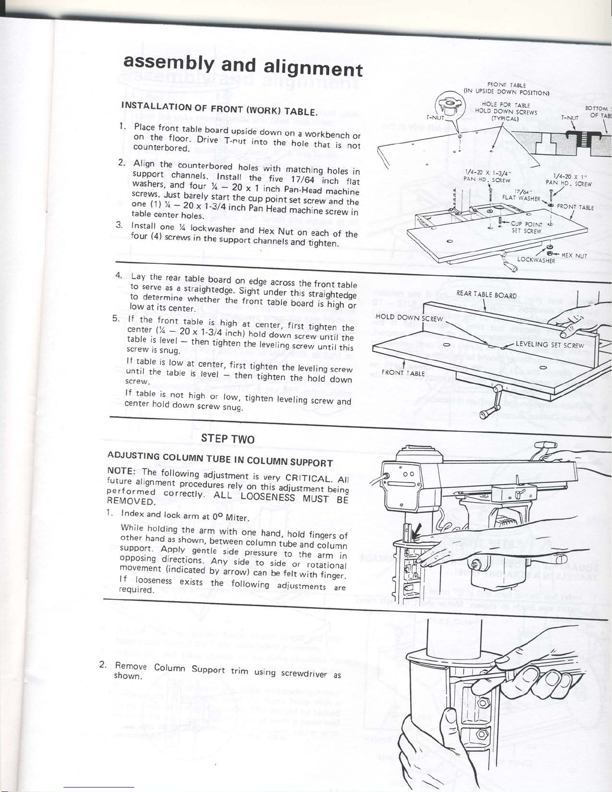
INSTALLATTON
OF
FRONT
(WORK)
TABLE.
1.
Place
front
table
board
upside
down
on
a workbench
or
on
the
f
loor.
Drive
f_"ui
into
-ir,J'iJr.,
that
is
not
counterbored.
FRONT
TABLT
EOITOM
S
OFI
2.
3.
Align
the
counterbored
.holes
with
matching
holes
in
support
channels.
Instail
the
tir:"
l)ifil'"tnch
flat
washers,
and
four
%
_.2g
" ii""i.,-p#-'H?o
macnine
screvvs.
Just
barety
start
the
gup
poin;;;;'r;"ie"w
and
the
one
(1)
%
-
20
x 1-3/4
inch
pii
i;J
il;riJ
screw
,n
table
center
holes-
Install
one
%
lockwasher
and
Hex
Nut
on
each
of
the
four
(4)
screws
in
the
support
channels
and
tighten.
l-
:+cuP
PO|NT
sET
SCREW
4.
,fL::: ::.: ::_b],._.b:.,d
ol
edge
across
the
front
tabre
["J,ffn'
jJi"n?l".ogi^tj-t-iT4;il:':Jffi
;;1'J:
f_ffil::,whether
ir,.
r."t
i.ir;
il'o'i1,il;ii.:;
low
at
its
center.
5.
lf
the front
table
is,trigh.
at
center,
first
tighten
the
center (%
_
20
x 1-3/4
,inch)
notO
Oown
screw
until
the
table
is
tevel
_
then
lishlen
th;i;;;'#w
untitthis
screw
is
snug.
lf
table
is
low
at
center.
first
tighten
the
leveling
screw
untir
the
tabte
is
tevet
_
til
i;e;;;"inJ
noro
oo*n
screw.
it-
taOtg
is.not
high
or
low,
tighten
leveling
screw
anol
center
hold
down
screw
snuq.
LEVETING
SET
SCREW
FRONT
TABLE
STEP
TWO
ADJUSTING
COLUMN
TUBE
IN
COLUMN
SUPPORT
|.9TE: ,The
fo,owing
adjustment
is
very
CRtTICAL.
Atl
l1Y: -1is",t.nt
pro"-"durgl
l.rv
on
th is'adlustment
bei
no
BtilB'rft;1
correctry.
ALL'Looa-irui"dj"
rvrUii";;
1.
Index
and
lock
arm
at
0o
Miter.
While
holding
the
arm
rrvith
one
hand,
hold
fingers
of
other
hand
as
shown,
between
column
iuOe
ano
column
:leeo1
Appty
gentte
side
presi"r.-;;-the
arm
in
opposing
directions.,
.Anv
,io.
1"-rid."",
rotational
movement
(indicated
by
arrow)
;
il;.;'*ith
finger.
lf
looseness
exists
the following
adjusrments
are
req
u
i red.
2.
Remove
Column
S
shown.
tupport
trim
using
screwdriver
as
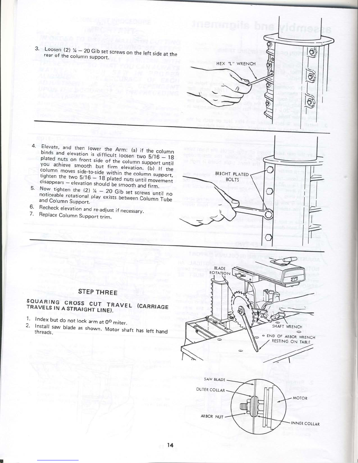
3.
L,oosen
(2')
%
-
20
Gib
set
screws
on
the
left
side
at
the
rear
of
the
column
support.
4.
Elevate,
and
then
bincts :nrr -,-.,-.,^-t?y:,l,lh".Arm:
(a)
if
the
column
binds
and
elevation
l;
_
.,."
^r,,,.
rd,
rr
rne
column
Dtarprr nr,+. ^^ 3_-_^
.diffic-ult
loosen
two
5/16
_
id
3:i1,1^ly::^"1
jl.it,iil.-ii;;";;ilT#
j:,;"1;
I:,i,j:T"::^.rT::,1
but
firm-.r.r.,i"".'i6)
tf
ths
n,r1g,nf:^,:o; :.,iJ"
*iir,
i"
ff
H;,i::ilo",l;
tighten
the
two
s/16
-
--
uurumn
support,
disanne:,. _ ar^.,^r:^_ -,
lg.plated
nuts
until
movement
d i
sappea
rs
-
e I
evat
i
on
rr,.i
r
I'
[.
ili
;:?,#.i
;i#:
5.
Now tinhto- rlr- /rr 1/ ^^ ^..
**":r*::,:f,.^-(^2,) !:
_
2g
Gib
;;;;;;;s
untir
no
::i'""':,?*:""t:l:l3lpr'v""i'ts-f
;;#'ff
Hirffi
and
Column
Support.
9
Recheck
elevation
and
re-adjust
if
necessary.
7.
Replace
Column
Support
trim.
STEP
THREE
SOUARING
CROSS
.C-U-T
TRAVEL
(CARRIAGE
TRAVELS
IN
A
STRAIGHT
LINE'.'-'"
I
i
Index
but
do
not
lock
arm
at
0o
miter.
,
|;:::[.:.w
btade
as
shown.
Moto.
,n"r
has
teft
hand
Saw
314P6
OUTER
COTLAR
e
END
OF
AREoR
wRENcH
RESTING
ON
IAELE
l4
ARBOR
NUT
INNER
COLLAR
 Loading...