

Covidien Nellcor Portable SpO2 Service manual
Service Manual
Nellcor
TM
Portable SpO2 Patient Monitoring System

COVIDIEN, COVIDIEN with logo, and Covidien logo and Positive Results for Life are U.S. and internationally registered
trademarks of Covidien AG. ™* brands are trademarks of their respective owner. Other brands are trademarks of a Covidien
company.

Table of Contents
1 Introduction
1.1 Overview . . . . . . . . . . . . . . . . . . . . . . . . . . . . . . . . . . . . . . . . . . . . . . . . . . . . . . . . . . . . . . . . . . . 1-1
1.2 Safety Information . . . . . . . . . . . . . . . . . . . . . . . . . . . . . . . . . . . . . . . . . . . . . . . . . . . . . . . . . . 1-2
1.2.1 Safety Symbols . . . . . . . . . . . . . . . . . . . . . . . . . . . . . . . . . . . . . . . . . . . . . . . . . . . . . . . . . . . . . . . . . . . . . . .1-2
1.2.2 Explosion, Shock, and Toxicity Hazards . . . . . . . . . . . . . . . . . . . . . . . . . . . . . . . . . . . . . . . . . . . . . . . .1-2
1.2.3 Service Procedures . . . . . . . . . . . . . . . . . . . . . . . . . . . . . . . . . . . . . . . . . . . . . . . . . . . . . . . . . . . . . . . . . . . 1-3
1.2.4 Monitoring System Operation and Service . . . . . . . . . . . . . . . . . . . . . . . . . . . . . . . . . . . . . . . . . . . .1-4
1.2.5 Patient Monitoring and Safety . . . . . . . . . . . . . . . . . . . . . . . . . . . . . . . . . . . . . . . . . . . . . . . . . . . . . . . . 1-5
1.2.6 Monitoring System Readings . . . . . . . . . . . . . . . . . . . . . . . . . . . . . . . . . . . . . . . . . . . . . . . . . . . . . . . . .1-5
1.2.7 Sensors, Cables, and Other Accessories . . . . . . . . . . . . . . . . . . . . . . . . . . . . . . . . . . . . . . . . . . . . . . .1-6
1.2.8 Electromagnetic Interference . . . . . . . . . . . . . . . . . . . . . . . . . . . . . . . . . . . . . . . . . . . . . . . . . . . . . . . . . 1-6
1.2.9 Connections with Other Equipment . . . . . . . . . . . . . . . . . . . . . . . . . . . . . . . . . . . . . . . . . . . . . . . . . . 1-7
1.2.10 Monitoring System Storage, Transport, and Disposal . . . . . . . . . . . . . . . . . . . . . . . . . . . . . . . . . .1-7
1.3 Obtaining Technical Assistance . . . . . . . . . . . . . . . . . . . . . . . . . . . . . . . . . . . . . . . . . . . . . . 1-8
1.3.1 Technical Services . . . . . . . . . . . . . . . . . . . . . . . . . . . . . . . . . . . . . . . . . . . . . . . . . . . . . . . . . . . . . . . . . . . .1-8
1.3.2 Related Documents . . . . . . . . . . . . . . . . . . . . . . . . . . . . . . . . . . . . . . . . . . . . . . . . . . . . . . . . . . . . . . . . . .1-8
1.4 Warranty Information . . . . . . . . . . . . . . . . . . . . . . . . . . . . . . . . . . . . . . . . . . . . . . . . . . . . . . . 1-9
2 Service Menu Options
2.1 Overview . . . . . . . . . . . . . . . . . . . . . . . . . . . . . . . . . . . . . . . . . . . . . . . . . . . . . . . . . . . . . . . . . . . 2-1
2.2 Safety Reminders . . . . . . . . . . . . . . . . . . . . . . . . . . . . . . . . . . . . . . . . . . . . . . . . . . . . . . . . . . . 2-1
2.3 Service Menu Overview . . . . . . . . . . . . . . . . . . . . . . . . . . . . . . . . . . . . . . . . . . . . . . . . . . . . . 2-1
2.3.1 Power On Settings . . . . . . . . . . . . . . . . . . . . . . . . . . . . . . . . . . . . . . . . . . . . . . . . . . . . . . . . . . . . . . . . . . . . 2-3
2.3.2 Permission to Mute Alarm . . . . . . . . . . . . . . . . . . . . . . . . . . . . . . . . . . . . . . . . . . . . . . . . . . . . . . . . . . . . 2-3
2.3.3 Alarm Silence Duration . . . . . . . . . . . . . . . . . . . . . . . . . . . . . . . . . . . . . . . . . . . . . . . . . . . . . . . . . . . . . . . 2-4
2.3.4 Power Saving Settings . . . . . . . . . . . . . . . . . . . . . . . . . . . . . . . . . . . . . . . . . . . . . . . . . . . . . . . . . . . . . . . . 2-4
2.3.5 Battery Type . . . . . . . . . . . . . . . . . . . . . . . . . . . . . . . . . . . . . . . . . . . . . . . . . . . . . . . . . . . . . . . . . . . . . . . . . .2-4
2.3.6 Date/Time Settings . . . . . . . . . . . . . . . . . . . . . . . . . . . . . . . . . . . . . . . . . . . . . . . . . . . . . . . . . . . . . . . . . . . 2-4
2.3.7 Communication Settings . . . . . . . . . . . . . . . . . . . . . . . . . . . . . . . . . . . . . . . . . . . . . . . . . . . . . . . . . . . . . 2-4
2.3.8 Alarm Priority Settings . . . . . . . . . . . . . . . . . . . . . . . . . . . . . . . . . . . . . . . . . . . . . . . . . . . . . . . . . . . . . . . .2-5
2.3.9 Languages . . . . . . . . . . . . . . . . . . . . . . . . . . . . . . . . . . . . . . . . . . . . . . . . . . . . . . . . . . . . . . . . . . . . . . . . . . .2-5
2.3.10 Dynamic Password . . . . . . . . . . . . . . . . . . . . . . . . . . . . . . . . . . . . . . . . . . . . . . . . . . . . . . . . . . . . . . . . . . . 2-5
2.3.11 Enable PCSync Mode . . . . . . . . . . . . . . . . . . . . . . . . . . . . . . . . . . . . . . . . . . . . . . . . . . . . . . . . . . . . . . . . . 2-5
2.3.12 About Monitor . . . . . . . . . . . . . . . . . . . . . . . . . . . . . . . . . . . . . . . . . . . . . . . . . . . . . . . . . . . . . . . . . . . . . . .2-5
2.3.13 Covidien Service . . . . . . . . . . . . . . . . . . . . . . . . . . . . . . . . . . . . . . . . . . . . . . . . . . . . . . . . . . . . . . . . . . . . . . 2-6
3 Data Management
3.1 Overview . . . . . . . . . . . . . . . . . . . . . . . . . . . . . . . . . . . . . . . . . . . . . . . . . . . . . . . . . . . . . . . . . . . 3-1
3.2 External Data Communication . . . . . . . . . . . . . . . . . . . . . . . . . . . . . . . . . . . . . . . . . . . . . . . 3-1
3.2.1 Monitoring History Download . . . . . . . . . . . . . . . . . . . . . . . . . . . . . . . . . . . . . . . . . . . . . . . . . . . . . . . . 3-2
Service Manual i

3.3 Firmware Upgrade . . . . . . . . . . . . . . . . . . . . . . . . . . . . . . . . . . . . . . . . . . . . . . . . . . . . . . . . . 3-11
4 Modification and Testing
4.1 Overview . . . . . . . . . . . . . . . . . . . . . . . . . . . . . . . . . . . . . . . . . . . . . . . . . . . . . . . . . . . . . . . . . . . 4-1
4.2 Required Equipment . . . . . . . . . . . . . . . . . . . . . . . . . . . . . . . . . . . . . . . . . . . . . . . . . . . . . . . . 4-2
4.3 System Performance Tests . . . . . . . . . . . . . . . . . . . . . . . . . . . . . . . . . . . . . . . . . . . . . . . . . . 4-2
4.3.1 Power-On Self-Test (POST) . . . . . . . . . . . . . . . . . . . . . . . . . . . . . . . . . . . . . . . . . . . . . . . . . . . . . . . . . . . .4-2
4.3.2 Battery Status . . . . . . . . . . . . . . . . . . . . . . . . . . . . . . . . . . . . . . . . . . . . . . . . . . . . . . . . . . . . . . . . . . . . . . . . . 4-3
4.3.3 Patient Modes . . . . . . . . . . . . . . . . . . . . . . . . . . . . . . . . . . . . . . . . . . . . . . . . . . . . . . . . . . . . . . . . . . . . . . . . 4-4
4.3.4 Homecare Mode . . . . . . . . . . . . . . . . . . . . . . . . . . . . . . . . . . . . . . . . . . . . . . . . . . . . . . . . . . . . . . . . . . . . .4-5
4.3.5 Sleep Study Mode . . . . . . . . . . . . . . . . . . . . . . . . . . . . . . . . . . . . . . . . . . . . . . . . . . . . . . . . . . . . . . . . . . . . 4-6
4.3.6 Dynamic Passwords . . . . . . . . . . . . . . . . . . . . . . . . . . . . . . . . . . . . . . . . . . . . . . . . . . . . . . . . . . . . . . . . . . 4-7
4.3.7 Date and Time . . . . . . . . . . . . . . . . . . . . . . . . . . . . . . . . . . . . . . . . . . . . . . . . . . . . . . . . . . . . . . . . . . . . . . . . 4-9
4.4 Operational and Functional Tests . . . . . . . . . . . . . . . . . . . . . . . . . . . . . . . . . . . . . . . . . . . 4-10
4.4.1 General Operation Tests . . . . . . . . . . . . . . . . . . . . . . . . . . . . . . . . . . . . . . . . . . . . . . . . . . . . . . . . . . . . .4-10
4.4.2 Functional Tests . . . . . . . . . . . . . . . . . . . . . . . . . . . . . . . . . . . . . . . . . . . . . . . . . . . . . . . . . . . . . . . . . . . . .4-26
4.5 Verification Check Sheets . . . . . . . . . . . . . . . . . . . . . . . . . . . . . . . . . . . . . . . . . . . . . . . . . . 4-45
5 Troubleshooting
5.1 Overview . . . . . . . . . . . . . . . . . . . . . . . . . . . . . . . . . . . . . . . . . . . . . . . . . . . . . . . . . . . . . . . . . . . 5-1
5.2 Troubleshooting Guide . . . . . . . . . . . . . . . . . . . . . . . . . . . . . . . . . . . . . . . . . . . . . . . . . . . . . 5-1
5.2.1 Error Conditions by Category . . . . . . . . . . . . . . . . . . . . . . . . . . . . . . . . . . . . . . . . . . . . . . . . . . . . . . . . . 5-2
5.2.2 System Error Codes . . . . . . . . . . . . . . . . . . . . . . . . . . . . . . . . . . . . . . . . . . . . . . . . . . . . . . . . . . . . . . . . . . .5-6
5.3 Return . . . . . . . . . . . . . . . . . . . . . . . . . . . . . . . . . . . . . . . . . . . . . . . . . . . . . . . . . . . . . . . . . . . . . 5-8
6 Repair
6.1 Overview . . . . . . . . . . . . . . . . . . . . . . . . . . . . . . . . . . . . . . . . . . . . . . . . . . . . . . . . . . . . . . . . . . . 6-1
6.2 Spare Parts and Accessories . . . . . . . . . . . . . . . . . . . . . . . . . . . . . . . . . . . . . . . . . . . . . . . . . 6-2
6.3 Required Tools . . . . . . . . . . . . . . . . . . . . . . . . . . . . . . . . . . . . . . . . . . . . . . . . . . . . . . . . . . . . . 6-4
6.4 Battery Replacement . . . . . . . . . . . . . . . . . . . . . . . . . . . . . . . . . . . . . . . . . . . . . . . . . . . . . . . 6-4
6.4.1 Remove the Batteries . . . . . . . . . . . . . . . . . . . . . . . . . . . . . . . . . . . . . . . . . . . . . . . . . . . . . . . . . . . . . . . . . 6-5
6.4.2 Replace the Batteries . . . . . . . . . . . . . . . . . . . . . . . . . . . . . . . . . . . . . . . . . . . . . . . . . . . . . . . . . . . . . . . . . 6-5
6.5 Disassembly and Reassembly . . . . . . . . . . . . . . . . . . . . . . . . . . . . . . . . . . . . . . . . . . . . . . . 6-6
6.5.1 Front and Rear Assembly Replacement . . . . . . . . . . . . . . . . . . . . . . . . . . . . . . . . . . . . . . . . . . . . . . . 6-6
6.5.2 NELL1SR Board Replacement . . . . . . . . . . . . . . . . . . . . . . . . . . . . . . . . . . . . . . . . . . . . . . . . . . . . . . . . . 6-8
6.5.3 Main Board Replacement . . . . . . . . . . . . . . . . . . . . . . . . . . . . . . . . . . . . . . . . . . . . . . . . . . . . . . . . . . . . . 6-9
6.5.4 Coin Cell Battery Replacement . . . . . . . . . . . . . . . . . . . . . . . . . . . . . . . . . . . . . . . . . . . . . . . . . . . . . . .6-11
6.5.5 LCD Replacement . . . . . . . . . . . . . . . . . . . . . . . . . . . . . . . . . . . . . . . . . . . . . . . . . . . . . . . . . . . . . . . . . . .6-12
6.5.6 PI Cable and Cable Housing Replacement . . . . . . . . . . . . . . . . . . . . . . . . . . . . . . . . . . . . . . . . . . .6-13
ii Service Manual

List of Tables
Table1-1.Safety Symbol Definitions...............................................................................1-2
Table2-1.Service Menu Settings......................................................................................2-2
Table3-1.Monitoring Status Codes.................................................................................3-6
Table4-1.Required Test Equipment ...............................................................................4-2
Table4-2.Patient Modes .....................................................................................................4-5
Table4-3.Functional Tests with SRC-MAX................................................................. 4-27
Table5-1.Error Conditions and Resolutions ................................................................5-2
Table5-2.System Error Codes ...........................................................................................5-6
Table6-1.Spare Parts List by Callout Number .............................................................6-2
Table6-2.Monitoring System Accessories....................................................................6-4
Service Manual iii

Page Left Intentionally Blank
iv Service Manual

List of Figures
Figure2-1. Service Menu ................................................................................................................. 2-3
Figure3-1. Mini-USB Port ................................................................................................................ 3-3
Figure3-2. Transfer Data Type ...................................................................................................... 3-4
Figure3-3. Transfer Data by USB .................................................................................................. 3-4
Figure3-4. Sample Monitoring History Printout .................................................................... 3-5
Figure3-5. Sample Bridge Driver Installer Window .............................................................. 3-7
Figure3-6. Sample New Hardware Wizard Screen ................................................................ 3-7
Figure3-7. Device Manager Button, Hardware Tab .............................................................. 3-8
Figure3-8. Sample Hardware List in Device Manager Window ........................................ 3-9
Figure3-9. Sample Initial USB to UART Bridge Properties Window .............................. 3-10
Figure3-10. Baud Rate List, Port Settings Tab ....................................................................... 3-11
Figure3-11. Firmware Upgrade Mode ..................................................................................... 3-12
Figure3-12. Firmware Upgrade, PCSync™* Utility ............................................................... 3-12
Figure3-13. Firmware Upgrade Process ................................................................................. 3-13
Figure3-14. POST Screen and Firmware Version ................................................................. 3-14
Figure4-1. Power-On Self-Test Sequence ................................................................................ 4-3
Figure4-2. Change Patient Mode Menu ................................................................................... 4-4
Figure4-3. Homecare Mode Menu Item ................................................................................... 4-5
Figure4-4. Homecare Mode Monitoring Screen .................................................................... 4-6
Figure4-5. Sleep Study Mode Menu Item ................................................................................ 4-7
Figure4-6. Service Menu ................................................................................................................. 4-8
Figure4-7. Dynamic Password Menu (Homecare to Standard Example) ...................... 4-8
Figure4-8. Password Set or Reset (Homecare to Standard Example) ............................ 4-9
Figure4-9. Date/Time Settings ..................................................................................................... 4-9
Figure4-10. Sensor Port ................................................................................................................ 4-10
Figure4-11. Sensor Port ................................................................................................................ 4-11
Figure4-12. Low SpO2 Alarm Limit of 99% ............................................................................ 4-12
Figure4-13. Low Pulse Alarm Limit of 160BPM .................................................................... 4-13
Figure4-14. Alarm Silence Duration Setting of 30 Seconds ............................................ 4-14
Figure4-15. Permission to Mute Alarm ................................................................................... 4-15
Figure4-16. Confirmation for Muted Alarm ........................................................................... 4-15
Figure4-17. Alarm Volume Default Setting of 2 ................................................................... 4-17
Figure4-18. Key Beep Volume Default Setting of 0 ............................................................ 4-18
Figure4-19. Pulse Volume Default Setting of 0 .................................................................... 4-19
Figure4-20. Brightness Setting .................................................................................................. 4-20
Figure4-21. “Spot Reading Saved” Message ......................................................................... 4-21
Figure4-22. Monitoring History Spot Data ............................................................................ 4-21
Figure4-23. Sensor Disconnect Alarm Priority Setting ...................................................... 4-22
Figure4-24. Sensor Off Alarm ..................................................................................................... 4-23
Figure4-25. Screen Saver Time Setting ................................................................................... 4-24
Figure4-26. Auto Power Off Time Setting .............................................................................. 4-26
Figure4-27. SRC-MAX Oximetry Tester ................................................................................... 4-28
Figure4-28. SRC-MAX Tester-Generated Waveform .......................................................... 4-29
Service Manual v

Figure4-29. SRC-MAX Increase to 200 BPM .......................................................................... 4-30
Figure4-30. SRC-MAX Decrease to 60 BPM ........................................................................... 4-30
Figure4-31. SRC-MAX %SpO2 Increase to 90 ....................................................................... 4-31
Figure4-32. SRC-MAX %SpO2 Decrease to 75 ..................................................................... 4-32
Figure4-33. SRC-MAX High Modulation ................................................................................. 4-33
Figure4-34. BPM of 200 with High Modulation ................................................................... 4-34
Figure4-35. BPM of 60 with High Modulation ...................................................................... 4-35
Figure4-36. %SpO2 of 90 with High Modulation ................................................................ 4-36
Figure4-37. %SpO2 of 75 with High Modulation ................................................................ 4-37
Figure4-38. %SpO2 of 75 with Low Modulation ................................................................. 4-38
Figure4-39. High Light Condition ............................................................................................. 4-39
Figure4-40. BPM of 200 with High Light Condition ........................................................... 4-40
Figure4-41. BPM of 60 with High Light Condition .............................................................. 4-41
Figure4-42. %SpO2 of 90 with High Light Condition ........................................................ 4-42
Figure4-43. %SpO2 of 75 with High Light Condition ........................................................ 4-43
Figure4-44. High Modulation and High Light Condition ................................................. 4-44
Figure5-1. Return Packaging ......................................................................................................... 5-9
Figure6-1. Exploded View ............................................................................................................... 6-2
Figure6-2. Standard Cover (3 Shown) and Ambulatory Cover ......................................... 6-4
Figure6-3. Battery Replacement .................................................................................................. 6-5
Figure6-4. Front and Rear Assembly Replacement ............................................................... 6-7
Figure6-5. NELL1SR Board Replacement .................................................................................. 6-9
Figure6-6. Main Board Replacement ....................................................................................... 6-10
Figure6-7. Coin Cell Battery Replacement ............................................................................. 6-11
Figure6-8. LCD Replacement ..................................................................................................... 6-12
Figure6-9. PI Cable and Cable Housing Replacement ...................................................... 6-13
vi Service Manual

1 Introduction
1.1 Overview
This manual contains information for servicing the Nellcor™ portable SpO2 patient monitoring
system.
This manual applies to the following product:
Note:
Before use, carefully read this manual, the Operator’s Manual, accessory Instructions for Use, and all
precautionary information and specifications.
Reference the Operator’s Manual for the following information:
• Intended Use statement
PM10N
• Operations-related warnings and cautions
• Overviews of the display and operating buttons
• Descriptions of product and packaging symbols
• Installation and operation instructions
• Alarms management
• Preventive maintenance
• Performance considerations
• Accessories
• Theory of operations
• Product specifications
• Clinical studies
1-1
Introduction
Safety Information
1.2
This section contains important safety information related to general use of the Nellcor™ portable
patient monitoring system. Other important safety information appears throughout the
SpO
2
manual. The Nellcor™ portable SpO2 patient monitoring system is referred to as the “monitoring
system” throughout this manual.
1.2.1 Safety Symbols
Table1-1.Safety Symbol Definitions
Symbol Definition
WARNING
Alerts users to potential serious outcomes (death, injury, or adverse events) to the
patient, user, or environment.
Caution
Identifies conditions or practices that could result in damage to the equipment or
other property.
Note
Provides additional guidelines or information.
1.2.2 Explosion, Shock, and Toxicity Hazards
WARNING:
Explosion hazard — Do not use the monitoring system in the presence of flammable anesthetics.
WARNING:
Shock hazard—Do not pour or spill liquids onto the monitoring system.
WARNING:
Shock hazard—Firmly close the battery cover to prevent moisture from entering the monitoring
system.
WARNING:
The LCD panel (display) contains toxic chemicals. Do not touch broken LCD panels. Physical
contact with a broken LCD panel can result in transmission or ingestion of toxic substances.
1-2 Service Manual

1.2.3 Service Procedures
WARNING:
To avoid possible injury, do not attempt to service the monitoring system if there are any signs of
burning or smoking coming from the monitoring system.
WARNING:
Before attempting to service the monitoring system, disconnect it from the patient to avoid
possible injury to the patient.
WARNING:
Before attempting to disassemble the monitoring system, remove the batteries to prevent
possible injury.
WARNING:
Ensure that conductive portions of the electrodes, leads, and cable do not come into contact with
any other conductive parts.
Safety Information
WARNING:
High voltage is generated by the LCD backlight driver. Exercise caution when operating the
monitoring system with covers open.
WARNING:
Extreme care must be taken in modifying default or other settings to ensure they are appropriate
to the intended use.
WARNING:
Make sure to complete all performance tests in Chapter 4, Modification and Testing before placing
the monitoring system into operation after repair or maintenance. Failure to perform all tests
could result in erroneous monitoring system readings.
WARNING:
Any connections between this monitoring system and other devices must comply with applicable
medical systems safety standards such as IEC 60601-1. Failure to do so could result in unsafe
leakage current and grounding conditions.
WARNING:
To ensure accurate performance and prevent device failure, do not expose the monitoring system
to extreme moisture, such as direct exposure to rain. Such exposure may cause inaccurate
performance or device failure. Reference the Operator’s Manual for fluid ingress specifications.
Service Manual 1-3

Introduction
1.2.4 Monitoring System Operation and Service
WARNING:
Inspect the monitoring system and all accessories before use to ensure there are no signs of
physical damage or improper function. Do not use if damaged.
WARNING:
To ensure accurate performance and prevent device failure, do not expose the monitoring system
to extreme moisture, such as direct exposure to rain. Such exposure may cause inaccurate
performance or device failure. Do not immerse in water, solvents, or cleaning solutions, since the
monitoring system and pulse oximetry sensors and connectors are not waterproof.
WARNING:
Do not sterilize the monitoring system by irradiation, steam, or ethylene oxide.
WARNING:
The monitoring system should not be used adjacent to or stacked with other equipment. If
adjacent or stacked use is necessary, observe the monitoring system to verify normal operation in
the desired configuration.
WARNING:
The only user-serviceable parts inside the monitoring system are the four AA batteries. While users
can open the battery cover to change the batteries, only qualified service personnel should
remove the cover or access internal components for any other reason. Users should not modify
any components of the monitoring system.
WARNING:
Do not spray, pour, or spill any liquid on the monitoring system, its accessories, connectors,
switches, or openings in the casing, since this may cause damage to the monitoring system. Never
place fluids on the monitoring system. If fluid spills on the monitoring system, remove batteries,
wipe all components dry immediately, and have the monitoring system serviced to ensure no
hazard exists.
WARNING:
Do not damage the batteries by applying pressure. Do not throw, hit, drop, or impact the batteries.
WARNING:
Keep the monitoring system and batteries out of the reach of children.
Caution:
The monitoring system may not operate properly if it is operated or stored at conditions outside
the ranges stated in this manual, or if it is subjected to excessive shock or dropping.
1-4 Service Manual

1.2.5 Patient Monitoring and Safety
WARNING:
Always disconnect and remove the monitoring system and sensors during magnetic resonance
imaging (MRI) scanning. Attempting to use the monitoring system during an MRI procedure could
cause burns or adversely affect the MRI image or the monitoring system's accuracy.
WARNING:
Keep patients under close surveillance when monitoring. It is possible, although unlikely, that
radiated electromagnetic signals from sources external to the patient and the monitoring system
can cause inaccurate measurement readings.
WARNING:
As with all medical equipment, carefully route patient cabling to reduce the possibility of patient
entanglement or strangulation.
Safety Information
WARNING:
Do not lift or carry the monitoring system by the pulse oximetry sensor or pulse oximetry interface
cable. The cable may disconnect and cause the monitoring system to drop on a patient or cause
damage to monitoring system surfaces.
1.2.6 Monitoring System Readings
WARNING:
The monitoring system may remain attached to the patient during defibrillation or during use of
an electrosurgical unit; however, the monitoring system is not defibrillator-proof, and readings
may be inaccurate during defibrillation and shortly thereafter.
WARNING:
Check the patient's vital signs by alternate means should there be any doubt about the accuracy
of any measurement. Request a qualified service technician confirm the monitoring system is
functioning correctly.
WARNING:
For best product performance and measurement accuracy, use only accessories supplied or
recommended by Covidien. Use accessories according to their respective Instructions for Use.
Service Manual 1-5

Introduction
1.2.7 Sensors, Cables, and Other Accessories
WARNING:
Before use, carefully read the pulse oximetry sensor Instructions for Use, including all warnings,
cautions, and instructions.
WARNING:
Use only the Covidien-approved pulse oximetry sensors, interface cables, and accessories. Use of
other sensors, cables, and accessories can result in inaccurate readings and increased monitoring
system emissions.
WARNING:
Do not use any other cables to extend the length of the Covidien-approved interface cable.
Increasing the length will degrade signal quality and may lead to inaccurate measurements.
WARNING:
To prevent damage, avoid undue bending of the sensor cable.
WARNING:
The sensor disconnect error message and associated alarm indicate the pulse oximetry sensor is
either disconnected or has faulty wiring. Check the connection and, if necessary, replace the
sensor, the pulse oximetry cable, or both.
1.2.8 Electromagnetic Interference
WARNING:
Any radio frequency transmitting equipment or other nearby sources of electrical noise may result
in disruption of the monitoring system.
WARNING:
The monitoring system is designed for use in environments in which the signal can be obscured by
electromagnetic interference. During such interference, measurements may seem inappropriate
or the monitoring system may not seem to operate correctly.
WARNING:
Large equipment using a switching relay for its power on/off may affect monitoring system
operation. Do not operate the monitoring system in such environments.
1-6 Service Manual

Caution:
This device has been tested and found to comply with the limits for medical devices related to IEC
60601-1-2: 2007 and IEC 60601-1-2:2014. These limits are designed to provide reasonable
protection against harmful interference in a typical medical installation.
Caution:
This monitoring system generates, uses, and can radiate radio frequency energy and, if not
installed and used in accordance with the instructions, may cause harmful interference to other
devices in the vicinity. If interference is suspected, move pulse oximetry cables away from the
susceptible device.
Caution:
Be aware of possible interference from sources of electromagnetic interference, such as cellular
phones, radio transmitters, motors, telephones, lamps, electrosurgical units, defibrillators, and
other medical devices. If pulse oximetry readings are not as expected for the patient’s condition,
remove the sources of possible interference.
Safety Information
1.2.9 Connections with Other Equipment
Caution:
Accessory equipment connected to the monitoring system's data interface must be certified
according to IEC 60950-1 for data-processing equipment. All combinations of equipment must be
in compliance with IEC 60601-1 Requirements for Medical Electrical Systems. Anyone who
connects additional equipment to the signal input or signal output port configures a medical
system and is therefore responsible for ensuring the system complies with the requirements of IEC
60601-1, IEC 60601-1-2:2007, and IEC 60601-1-2:2014.
Caution:
When connecting the monitoring system to any instrument, verify proper operation before clinical
use.
Caution:
Anyone who connects a PC to the data output port configures a medical system and is therefore
responsible for ensuring that the system complies with the requirements of IEC 60601-1-1 and the
electromagnetic compatibility IEC 60601-1-2.
1.2.10 Monitoring System Storage, Transport, and Disposal
Caution:
Remove the batteries from the monitoring system before placing it in storage or when not using
it for a long period.
Service Manual 1-7

Introduction
Caution:
Do not short-circuit the batteries, as they may generate heat. To avoid short-circuiting, do not let
the batteries come in contact with metal objects at any time, especially during transport.
Caution:
Follow local government ordinances and recycling instructions regarding disposal or recycling of
the monitoring system and its components, including batteries and accessories.
1.3 Obtaining Technical Assistance
1.3.1 Technical Services
For technical information and assistance, contact Covidien or a local Covidien representative.
Covidien Technical Services: Patient Monitoring
15 Hampshire Street
Mansfield, MA 02048 USA
1.800.635.5267, 1.925.463.4635,
or contact a local Covidien representative
www.covidien.com
When calling Covidien or a local Covidien representative, have the monitoring system serial
number available. The serial number label is located on the bottom of the monitoring system.
Provide the firmware version number displayed during the power-on self-test (POST).
1.3.2 Related Documents
Nellcor™ Portable SpO2 Patient Monitoring System Operator’s Manual —
for operating the monitoring system and troubleshooting errors or malfunctions.
Nellcor™ Pulse Oximetry Sensor Instructions for Use — Guides sensor selection and usage. Before
attaching any of the various Covidien-approved pulse oximetry sensors to the monitoring system,
refer to the individual Instructions for Use.
Provides basic information
Nellcor™ Oxygen Saturation Accuracy Specification Grid — Provides sensor-specific guidance related
to desired SpO
monitoring system at
1-8 Service Manual
saturation accuracy measurements. Available online with the product manuals for the
2
www.covidien.com.

Warranty Information
Warranty Information
1.4
The information contained in this document is subject to change without notice. Covidien makes
no warranty of any kind with regard to this material, including, but not limited to, the implied
warranties of merchantability and fitness for a particular purpose. Covidien shall not be liable for
errors contained herein or for incidental or consequential damages in connection with the
furnishing, performance, or use of this material.
Service Manual 1-9

Introduction
Page Left Intentionally Blank
1-10 Service Manual

2 Service Menu Options
2.1 Overview
This chapter describes Service Menu settings for the Nellcor™ portable SpO2 patient monitoring
system. A password is required to access the Service Menu. Contact Technical Services
(reference Technical Services, page 1-8) for the default password.
2.2 Safety Reminders
WARNING:
For best product performance and measurement accuracy, use only accessories supplied or
recommended by Covidien. Use accessories according to their respective Instructions for Use.
WARNING:
The sensor disconnect error message and associated alarm indicate the pulse oximetry sensor is
either disconnected or has faulty wiring. Check the connection and, if necessary, replace the
sensor, the pulse oximetry cable, or both.
WARNING:
Do not use damaged pulse oximetry sensors. Do not use with exposed optical components. Do
not immerse completely in water, solvents, or cleaning solutions, since pulse oximetry sensors
and connectors are not waterproof. Do not sterilize by irradiation, steam or ethylene oxide. Refer
to the cleaning instructions in the Instructions for Use for reusable sensors.
Caution:
Do not attach any cable intended for computer use to the sensor port connector.
2.3 Service Menu Overview
WARNING:
Only qualified service personnel should open the monitoring system housing, remove and
replace parts, or make adjustments.
2-1

Service Menu Options
The monitoring system contains a Service Menu that is accessible only by password. Contact
Technical Services (reference Technical Services, page 1-8) for the default passwords for all
restricted menus and functions.
The monitoring system ships with the Service Menu factory default settings listed in Table 2-1. For
a list of the factory default settings for other menus, reference the Operator’s Manual.
Table2-1.Service Menu Settings
Parameter Ranges/selection
Adult Pediatric Neonatal
Power On Settings Factory Defaults, Institutional Defaults, Last Setting Factory Defaults
Permission to Mute Alarm No, Yes No
Alarm Silence Duration 30, 60, 90, 120 seconds 120 seconds
Power Saving Settings Screen Saver Time:
Never, 1 - 10 minutes
Screen Saver Brightness:
0% - 50% in 10% increments
Auto Power Off Time:
Never, 1 - 10 minutes
Battery Type Lithium, Alkaline Lithium
Date/Time Settings Date Format:
YY/MM/DD, DD/MM/YY, MM/DD/YY
Communication Settings Serial Connectivity Settings:
ASCII 19200, ASCII 115200,
SPDout 19200, SPDout 115200
Alarm Priority Settings Low, Medium, High:
- Sensor Disconnect
- Sensor Off
- Sensor Failure
Factory default
3 minutes
20%
3 minutes
YY/MM/DD
ASCII, 19200
Low
Low, Medium, High:
- SpO
High
2
- Pulse Rate High
Medium, High:
Low
- SpO
2
- Pulse Rate Low
Languages Chinese, Czech, Danish, Dutch, English, Finnish,
French, German, Greek, Hungarian, Italian,
Japanese, Korean, Norwegian, Polish, Portuguese,
Russian, Slovakian, Spanish, Swedish, Turkish
Dynamic Password Passwords can be changed for entry into Homecare
Mode and Sleep Study Mode and back to Standard
Mode
Enable PCSync Mode On, Off Off
2-2 Service Manual
(Contact Technical Services)
Medium
Medium
English
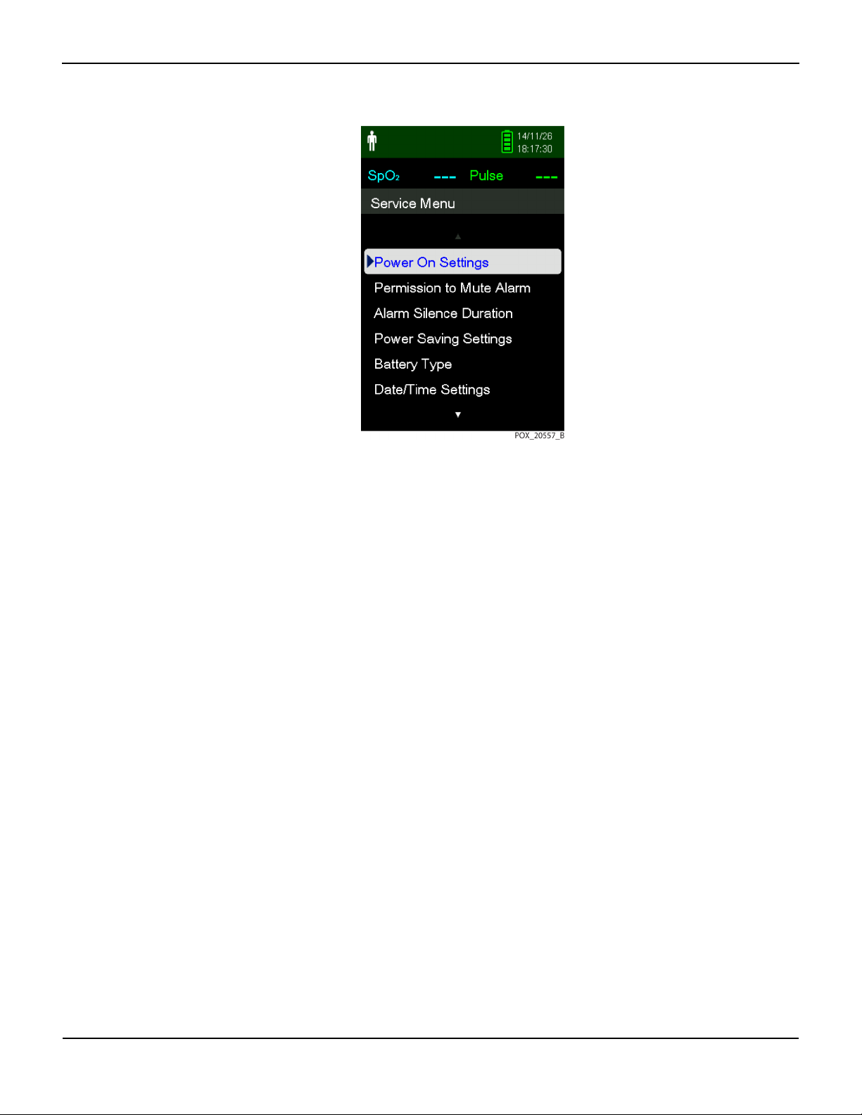
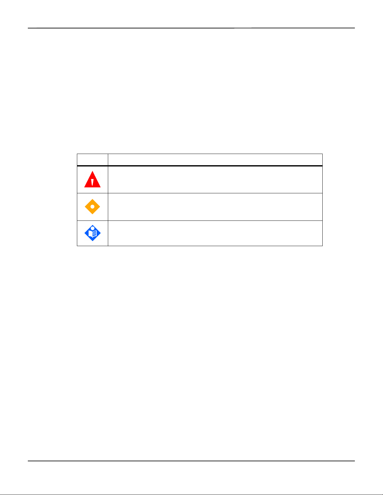
Figure2-1.Service Menu
Service Menu Overview
2.3.1 Power On Settings
Caution:
Last Settings should only be used in a service situation, not during normal operation.
Note:
Once changes are made to any settings, you must choose Last Settings or Institutional Defaults to have
those settings saved when the monitoring system is powered off.
Factory Defaults — The settings for the monitoring system when shipped from the manufacturer.
Choose this option to reset all values to factory defaults. (Default)
Institutional Defaults — The settings of the monitoring system for an individual institution or patient
situation. Set all desired parameters, then go to the Service Menu and select Institutional Defaults. The
monitoring system powers off once you exit the Service Menu. When you power on the monitoring
system again, the institutional defaults you set will be active. When you switch between operating
modes (for example, between Sleep Study Mode and Standard Mode), the institutional defaults are
retained.
Last Settings — The settings of the monitoring system are saved just before power off.
2.3.2 Permission to Mute Alarm
No — User cannot disable the audible alarm for SpO2 or pulse rate alarms. (Default)
Yes — User can disable the audible alarm for SpO
Service Manual 2-3
or pulse rate alarms.
2

Service Menu Options
Note:
The visual alarm (the yellow background behind the SpO
when the audible alarm is disabled.
2.3.3 Alarm Silence Duration
The amount of time the audible alarm remains silent after the Silence Alarm button is pressed.
Options include 30, 60, 90, and 120 seconds (default).
2.3.4 Power Saving Settings
Provides options for prolonging battery life during operation:
Screen Saver Time — By default, the screen dims after 3 minutes if no button is pressed. This value can
be changed to 1 - 10 minutes or Never. When the screen dims, pressing any button returns the screen
to normal brightness.
Screen Saver Brightness — By default, when the screen saver option is in effect, the screen dims to 20%
of full brightness after the specified time without a button press. This value can be changed to 0 - 50%
in 10% increments. When the screen dims, pressing any button returns the screen to normal
brightness.
or pulse rate reading) is always enabled, even
2
Auto Power Off Time — By default, the monitoring system powers off after 3 minutes if no button is
pressed. This value can be changed from 1 - 10 minutes or Never.
2.3.5 Battery Type
Provides power optimization when using different battery types:
• Lithium (default)
• Alkaline
2.3.6 Date/Time Settings
Provides options for the date format: YY/MM/DD (default), MM/DD/YY, or DD/MM/YY. Allows
manual setting of the year, month, and day, and the hour, minute, and second.
2.3.7 Communication Settings
The serial connectivity settings to be used when trend data is transferred from the monitoring
system to a PC using a USB cable. Options include:
• ASCII, 19200 baud (default)
• ASCII, 115200 baud
2-4 Service Manual

Service Menu Overview
SPDout, 19200 baud
•
• SPDout, 115200 baud
2.3.8 Alarm Priority Settings
Allows the setting of alarm priorities for Sensor Disconnect, Sensor Off, Sensor Failure, SpO2, and
Pulse Rate alarms. Reference Table 2-1 on page 2-2.
2.3.9 Languages
Displays most menu items in the chosen language (reference Table 2-1 on page 2-2 for the
complete list of languages). For some languages, certain menu items are not translated and
always display in English.
2.3.10 Dynamic Password
Allows changes to the passwords for switching between the following operating modes:
• Homecare to Standard Mode
• Standard to Homecare Mode
• Sleep Study to Standard Mode
• Standard to Sleep Study Mode
Contact Technical Services (reference Technical Services, page 1-8) for the default passwords.
Reference Dynamic Passwords, page 4-7 for instructions for changing these passwords.
2.3.11 Enable PCSync Mode
Enables use of the PCSync™* utility for testing the monitoring system and performing firmware
upgrades. Choices are On or Off (default).
2.3.12 About Monitor
Model Name — PM10N
System Software Version — The version of the software (firmware) loaded on the monitoring system
SpO
Module Version — The software version of the SpO2 circuit board installed in the monitoring
2
system
Service Manual 2-5

Service Menu Options
2.3.13 Covidien Service
For Covidien personnel only.
2-6 Service Manual

3 Data Management
3.1 Overview
This chapter contains information for accessing, transmitting, and downloading patient
monitoring data and history. This chapter also contains instructions for upgrading
firmware for the Nellcor™ portable SpO
system supports the following types of data viewing and transmission:
• Access stored monitoring history — Monitoring history (trend data) can be viewed
anytime it is stored in the monitoring system. Reference the Operator’s Manual.
• Download stored monitoring history — Monitoring history can be downloaded to a PC
using the HyperTerminal™* program or other data transmission and analysis tools.
• Upgrade the monitoring system’s firmware — Occasionally, Covidien will provide
upgrades to the firmware for the monitoring system, which must be loaded via the mini-USB
port.
3.2 External Data Communication
patient monitoring system. The monitoring
2
WARNING:
Any connections between this monitoring system and other devices must comply with
applicable medical systems safety standards such as IEC 60601-1 and applicable
collaterals. Failure to do so may result in unsafe leakage current and grounding
conditions.
Caution:
Do not attach any cable intended for computer use to the sensor port connector.
Caution:
Connect the monitoring system to a medical grade PC that is on an isolated AC circuit.
3-1

Data Management
3.2.1 Monitoring History Download
WARNING:
Replacing the coin cell battery for the main board resets the monitoring system’s date and
time settings. Integrity of existing patient data will be questionable. Reset the date and
time after replacing this battery with a known good battery.
Caution:
Anyone who connects a PC to the data output port configures a medical system and is
therefore responsible for ensuring that the system complies with the requirements of IEC
60601-1-1 and the electromagnetic compatibility IEC 60601-1-2.
Caution:
Signal artifacts, secondary to a variety of external factors, may compromise the presence
or accuracy of the displayed values.
Caution:
If the monitoring system does not contain its own isolation barrier, connect it to a medical
grade PC that is on an isolated AC circuit.
The monitoring system presents monitoring history (trend data) in tabular format. The
newest data values appear at the top.
To download monitoring history (trend data), connect by mini-USB port to a PC using the
HyperTerminal™* program or other data transmission and analysis tools. Any PC
connected to the data port must be certified according to IEC 60950. All combinations of
equipment must be in compliance with IEC 60601-1-1 system requirements.
Note:
Users may choose to import patient monitoring history to a spreadsheet program. To do so, export
monitoring history using the ASCII format option. Have a qualified service technician set this option
prior to attempting a data download.
System Compatibility Prerequisites
• Windows™* operating system
• HyperTerminal™* program or equivalent data transmission and analysis software installed on
the PC
Hardware
• Mini-USB data download cable
• CD or thumb drive, if USB driver required
3-2 Service Manual

Data transfer by USB port relies on existing communication software drivers for USB-based
devices already on the computer, so should not require any modification of the drivers used
by the USB interface. If, for some reason, the computer does not have the correct USB
driver, use the device driver provided on the product CD or from Technical Services.
Reference COM Port USB Driver Alternatives, page 3-6.
Note:
Any monitoring history download relies on either factory default settings or institutional default
settings established by a qualified service technician prior to usage. This includes baud rate and
communication protocol selection.
To download monitoring history using the HyperTerminal™* program
1. Configure the monitoring system’s serial connectivity settings appropriately.
2. Connect the monitoring system’s mini-USB port to the computer.
External Data Communication
Figure3-1.Mini-USB Port
3. Execute the HyperTerminal™* program.
Note:
If this is the first time the HyperTerminal™* program launches, it will prompt the user to set it
as the default Telnet program. Depending on institutional requirements, choose Yes or No.
4. Set appropriate port setting values for the HyperTerminal™* program:
a. Set the baud rate (bits per second) to match the monitoring system’s baud rate.
b. Ensure the data bit is set to 8.
c. Ensure the parity bit is set to none.
d. Ensure the stop bit is set to 1.
e. Ensure the flow control is set to off.
5. From the monitoring system’s Transfer Data menu, select Spot Data or Continuous Data.
Service Manual 3-3
Data Management
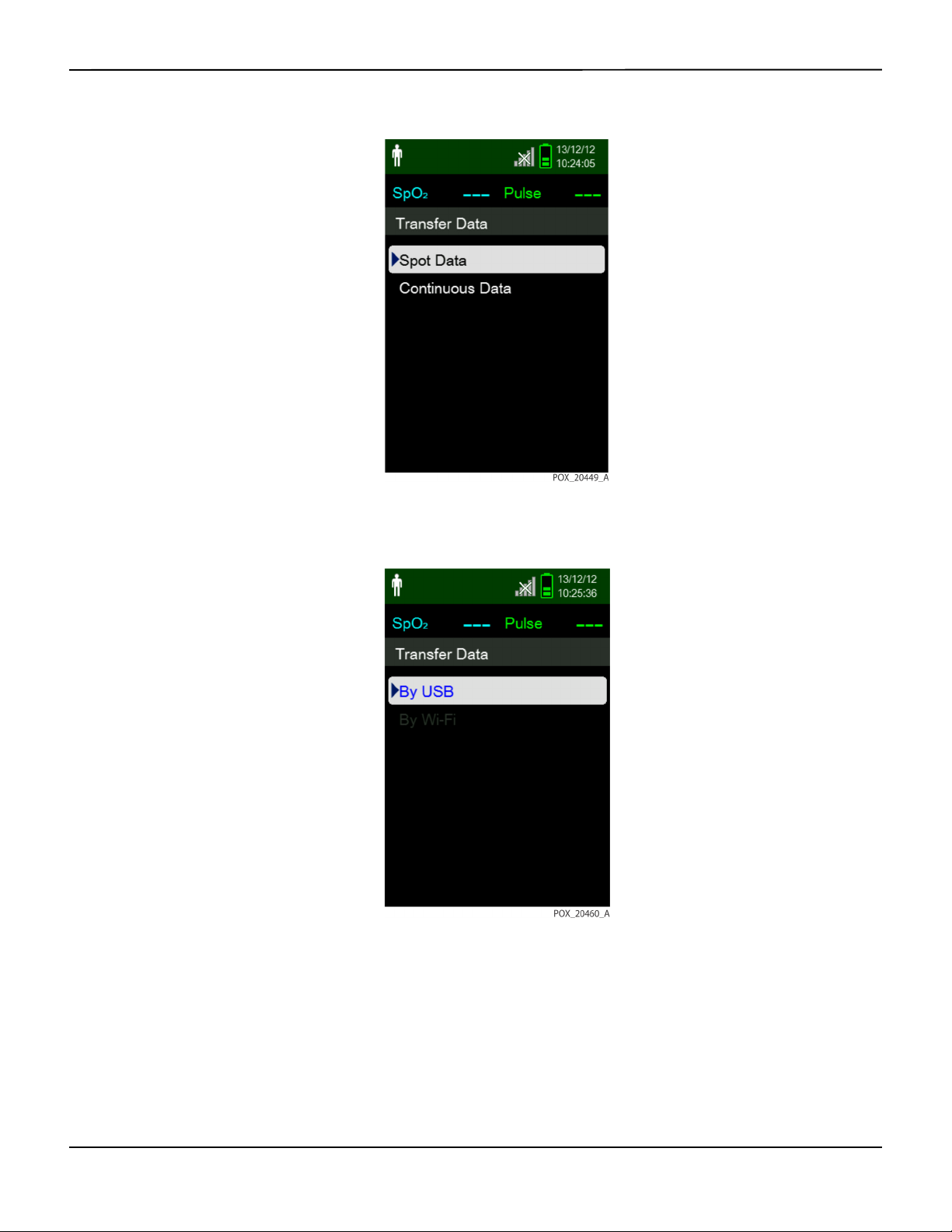
6. Select By USB.
Figure3-2.Transfer Data Type
Figure3-3.Transfer Data by USB
The data is transferred, and a progress bar is displayed. If desired, select Cancel to abort the
transmission.
The Output Complete message is displayed when the transmission is complete.
3-4 Service Manual
External Data Communication
To interpret downloaded monitoring history
1. Examine monitoring history on the HyperTerminal™* program screen, in a spreadsheet, or on
a printout from the personal computer.
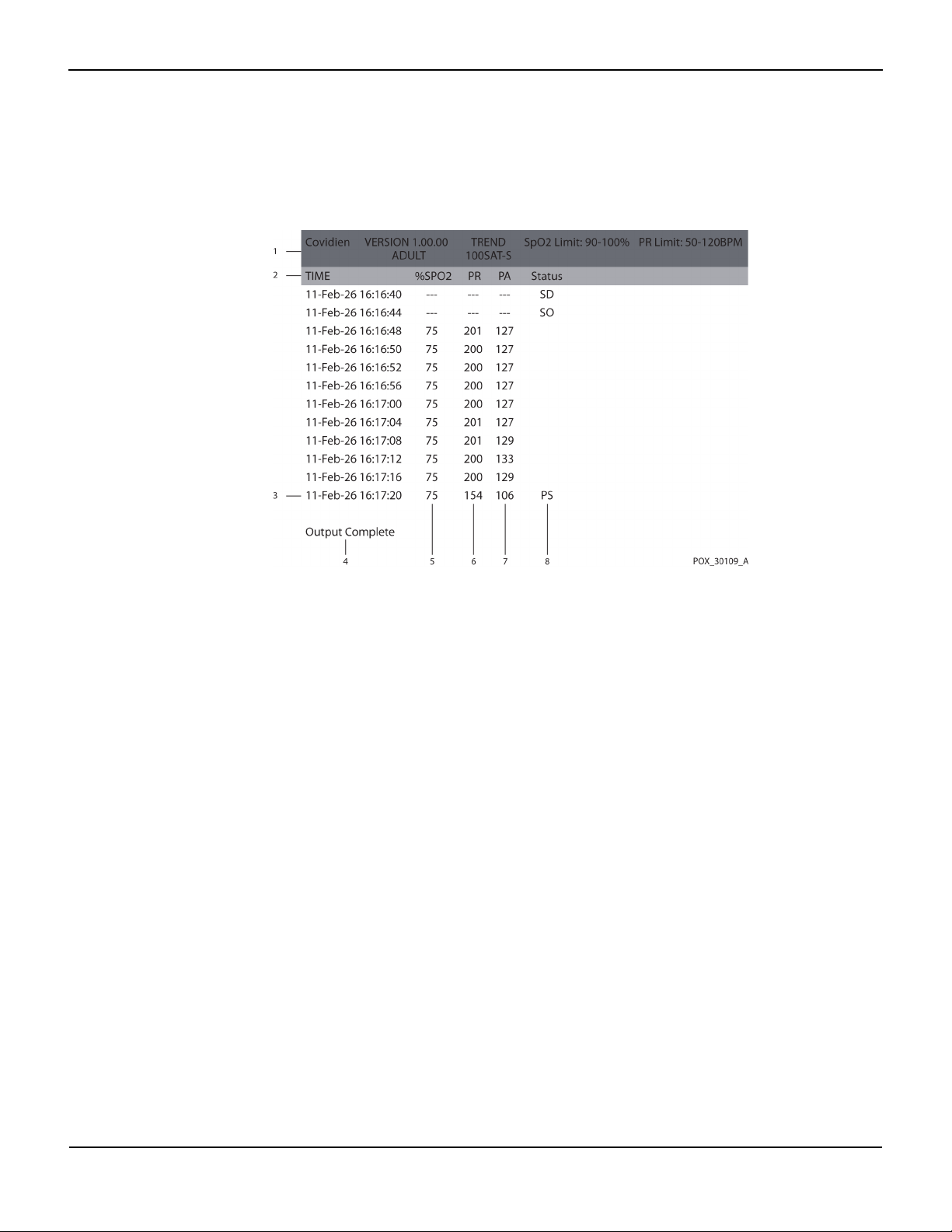
Figure3-4.Sample Monitoring History Printout
1 Product column headings Data source, firmware version, and system settings
2 Patient data column headings Lists appropriate time and data headings
3 Time column Real-time clock date and time stamp
4 Output Complete Message indicating completion of monitoring history
download
5 %SpO
6 PR Current pulse rate
7 PA Current pulse ampltitude
8 Status Operating status of the monitoring system
2. Ensure patient data settings coincide with expected settings. This would include the version of
2
Current saturation value
firmware and its CRC code, which should be all zeros; alarm limit settings; patient mode; and
SatSeconds™ setting.
3. Scan the time, SpO
4. Reference Table 3-1 on page 3-6 for descriptions of the operating status codes.
, or PR column until reaching the events of interest.
2
Service Manual 3-5

Data Management
Table3-1.Monitoring Status Codes
Status
code
LM Loss of pulse, patient motion
LP Loss of pulse
CB Critically low battery
LB Low battery
SO Sensor off
SD Sensor disconnect
AO Alarm off
AS Alarm silenced
MO Signal interference, patient motion
PS Pulse search
Description
COM Port USB Driver Alternatives
• Load the appropriate driver from the product CD into the connected computer.
• Contact Technical Services or a local Covidien representative.
To install a USB driver from the compact disc
1. Insert the Nellcor™ portable SpO
designated personal computer (PC).
2. Copy the COVIDIEN USB to UART Bridge Driver zip file to the PC, installing it in the desired
program folder.
3. Right-click on the zipped folder.
4. Select Extract All.
5. Open the extracted folder.
6. Launch the Driver Installer executable file.
Note:
To change the location of the driver, select the desired mapping by clicking Change Install
Location.
7. Click Install.
patient monitoring system compact disc (CD) into the
2
3-6 Service Manual
 Loading...