

Cornelius EVAPORATOR CONVERSION KIT WCC700, WCC700, 629096836 Instructions Manual
WCC700 Evaporator Retrofit Instructions
RETROFIT INSTRUCTIONS
WCC700 SERIES EVAPORATOR CONVERSION KIT (P/N 629096836)
The purpose of this kit is to convert a WCC700 Series icemaker from the non-reinforced evaporator
assembly to the reinforced (collared) evaporator assembly. This conversion will require replacing the
evaporator assembly, the dispense tray assembly and clamp, and the extruder head assembly.
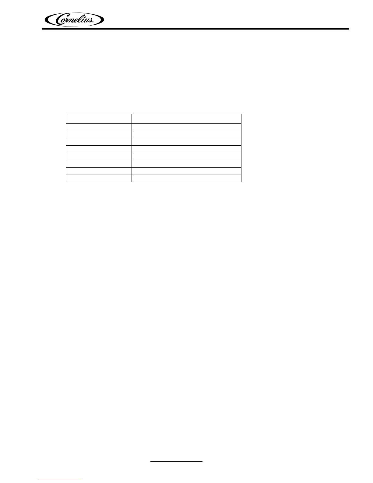
Parts List
Part Number Description
630000651 Evaporator Assembly
638036087 Clamp
638090219 Nylon Bearing
638090220 Delrin Bearing
638004393 Dryer, 1/4”
168833000 Lock Washer (4)
161179001 Bolt (4)
620516354INS Instructions
REPLACEMENT INSTRUCTIONS
1. Disconnect the icemaker from the power and water supplies.
2. Remove the top, front, and side panels in that order.
3. Recover the refrigerant from the icemaker using appropriate recovery techniques.
4. Drain the water from the evaporator by disconnecting the water feed line at the bottom of the
evaporator.
5. Remove the dispense tray cover and pull the auger assembly out of the evaporator. Set the cover
and assembly aside.
6. Remove the dispense tray assembly by loosening the screw clamp and pulling the tray off of the
evaporator. Retain this assembly for reuse.
7. Remove the insulation from the refrigerant lines at the expansion valve, at the inlet side of the
evaporator and the suction line, and at the outlet side of the evaporator, exposing the solder joints.
If the insulation is dry and undamaged, it can be re-used.
8. Protect the expansion valve from excessive heat by wrapping it with a cold wet rag or a commercial
heat protection product. Heat the joint between the valve and the evaporator inlet until it is hot
enough to separate, and then remove the expansion valve from the evaporator inlet. Separate the
suction line from the evaporator outlet in a similar manner.
9. Heat and remove the refrigerant filter dryer from the liquid line. Do not install the new dryer until
after the new evaporator assembly is installed.
10. Use a 7/16” wrench to un-bolt the base of the evaporator from the gear motor. Gently pry the base
upward and lift the evaporator off of the gear motor. Dispose of the evaporator per the current
warranty procedure.
11. Inspect the gear motor shaft seal for signs of leakage or damage. Replace as required. Lubricate
the shaft seal rubber with a food grade lubricant.
12. Place the new evaporator on the gear motor shaft seal. Carefully rotate the evap orator until the inlet
and outlet tubes are in the same location as they were with the previous evaporator. Apply antiseize (Loctite Silver Grade Anti-seize #76764) on the bolt threads, install the lock washer, and bolt
the evaporator to the gear motor.
Release Date: February 26, 2008 www.cornelius.com Revision: A
© 2008, IMI Cornelius Inc. - 1 - Publication Number: 620516354INS

WCC700 Evaporator Retrofit Instructions
13. Clean and braze the refrigeration connections at the evapo rator inlet and ou tlet using silver brazing
solder. Be careful to pr otect the expansion valve with a cold wet rag or a commerical heat protction
product.
14. Install the new ¼” dryer in the liquid line.
15. Pressure test the system for leaks with dry nitrogen.
IMPORTANT: Do not exceed the nameplate pressure ratings!
16. Evacuate the system to at least 500 microns.
17. Re-charge the system using a refrigerant scale or a Dial-a-Charge to the exact nameplate
specifications.
18. Re-insulate the refrigeration lines.
19. Install the dispense tray assembly with the new clamp and re-connect the water feed line.
20. Disassemble the auger assembly and inspect the bearings. Repl ace if nece ssar y. Reassemble the
auger assembly. Place the auger assembly into the evaporator and replace the dispense tray cover.
21. Restore the water supply and check for any leaks. Ensure that the evaporator fills to the correct
level. Adjust the float mechanism as required. Confirm that the float mechanism shuts off
completely once the correct water level is achieved.
22. Restore the power supply and ensure that the incoming voltage is within the nameplate ratings.
Confirm that the gear motor amp draw is within its nameplate rating. Refrigerant suction pressure
should settle at approximately 28 psig (R404-A).
23. Confirm that the icemaker is operating properly and replace the exterior panels.
Publication Number: 620516354INS - 2 - © 2008, IMI Cornelius Inc.
 Loading...