

Page 1
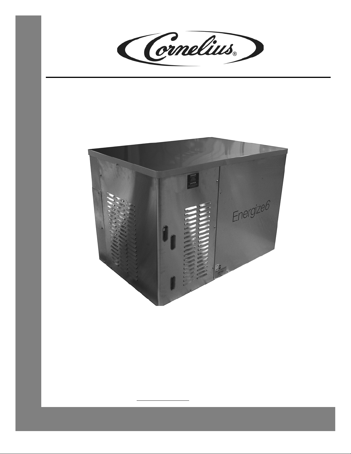
ENERGIZE6
Service Manual
Release Date: August 3, 2012
Publication Number: 621058457SER
Revision Date: August 8, 2013
Revision: A10
Visit the IMI Cornelius web site at www.cornelius.com for all your Literature needs.
Page 2

The products, technical information, and instructions contained in this manual are subject to change without notice.
These instructions are not intended to cover all details or variations of the equipment, nor to provide for every possible contingency in the installation, operation or maintenance of this equipment. This manual assumes that the person(s) working on the equipment have been trained and are skilled in working with electrical, plumbing, pneumatic,
and mechanical equipment. It is assumed that appropriate safety precautions are taken and that all local safety and
construction requirements are being met, in addition to the information contained in this manual.
This Product is warranted only as provided in Cornelius’ Commercial Warrant applicable to this Product and is subject to all of the restrictions and limitations contained in the Commercial Warranty.
Cornelius will not be responsible for any repair, replacement or other service required by or loss or damage resulting
from any of the following occurrences, including but not limited to, (1) other than normal and proper use and normal
service conditions with respect to the Product, (2) improper voltage, (3) inadequate wiring, (4) abuse, (5) accident,
(6) alteration, (7) misuse, (8) neglect, (9) unauthorized repair or the failure to utilize suitably qualified and trained persons to perform service and/or repair of the Product, (10) improper cleaning, (11) failure to follow installation, operating, cleaning or maintenance instructions, (12) use of “non-authorized” parts (i.e., parts that are not 100%
compatible with the Product) which use voids the entire warranty, (13) Product parts in contact with water or the
product dispensed which are adversely impacted by changes in liquid scale or chemical composition.
Contact Information:
To inquire about current revisions of this and other documentation or for assistance with any Cornelius product contact:
www.cornelius.com
38-3600
800-2
Trademarks and Copyrights:
This document contains proprietary information and it may not be reproduced in any way without permission from
Cornelius.
This document contains the original instructions for the unit described.
IMI CORNELIUS INC
Dr
101 Regency
Glendale Heights, IL
Tel: + 1 800-238-3600
Printed in U.S.A.
ive
Page 3

Safety Instructions. . . . . . . . . . . . . . . . . . . . . . . . . . . . . . . . . . . . . . . . . . . . . . . . . . . . . . . . . . . . . . . . . 1
Read and Follow ALL Safety Instructions . . . . . . . . . . . . . . . . . . . . . . . . . . . . . . . . . . . . . . . . . . . . . 1
Safety Overview . . . . . . . . . . . . . . . . . . . . . . . . . . . . . . . . . . . . . . . . . . . . . . . . . . . . . . . . . . . 1
Recognition . . . . . . . . . . . . . . . . . . . . . . . . . . . . . . . . . . . . . . . . . . . . . . . . . . . . . . . . . . . . . . 1
Different Types of Alerts. . . . . . . . . . . . . . . . . . . . . . . . . . . . . . . . . . . . . . . . . . . . . . . . . . . . . . . . 1
Safety Tips . . . . . . . . . . . . . . . . . . . . . . . . . . . . . . . . . . . . . . . . . . . . . . . . . . . . . . . . . . . . . . . . . . . . . 1
Qualified Service Personnel. . . . . . . . . . . . . . . . . . . . . . . . . . . . . . . . . . . . . . . . . . . . . . . . . . . . . . . . 2
Safety Precautions. . . . . . . . . . . . . . . . . . . . . . . . . . . . . . . . . . . . . . . . . . . . . . . . . . . . . . . . . . . . . . . 2
Shipping And Storage . . . . . . . . . . . . . . . . . . . . . . . . . . . . . . . . . . . . . . . . . . . . . . . . . . . . . . . . . . . . 2
CO2 (Carbon Dioxide) Warning . . . . . . . . . . . . . . . . . . . . . . . . . . . . . . . . . . . . . . . . . . . . . . . . . . . . . 2
System Overview . . . . . . . . . . . . . . . . . . . . . . . . . . . . . . . . . . . . . . . . . . . . . . . . . . . . . . . . . . . . . . . . . . 4
Description of Operation . . . . . . . . . . . . . . . . . . . . . . . . . . . . . . . . . . . . . . . . . . . . . . . . . . . . . . . . . . 4
Features. . . . . . . . . . . . . . . . . . . . . . . . . . . . . . . . . . . . . . . . . . . . . . . . . . . . . . . . . . . . . . . . . . . . . . . 4
Energy Efficiency . . . . . . . . . . . . . . . . . . . . . . . . . . . . . . . . . . . . . . . . . . . . . . . . . . . . . . . . . . . . . . . . 5
Specifications. . . . . . . . . . . . . . . . . . . . . . . . . . . . . . . . . . . . . . . . . . . . . . . . . . . . . . . . . . . . . . . . . . . 5
Operation . . . . . . . . . . . . . . . . . . . . . . . . . . . . . . . . . . . . . . . . . . . . . . . . . . . . . . . . . . . . . . . . . . . . . . . . 6
Starting the Unit . . . . . . . . . . . . . . . . . . . . . . . . . . . . . . . . . . . . . . . . . . . . . . . . . . . . . . . . . . . . . . . . . 6
Ending Operation . . . . . . . . . . . . . . . . . . . . . . . . . . . . . . . . . . . . . . . . . . . . . . . . . . . . . . . . . . . . . . . 10
Preventive Maintenance . . . . . . . . . . . . . . . . . . . . . . . . . . . . . . . . . . . . . . . . . . . . . . . . . . . . . . . . . . . 11
Cleaning and Sanitizing . . . . . . . . . . . . . . . . . . . . . . . . . . . . . . . . . . . . . . . . . . . . . . . . . . . . . . . . . . 11
Changing to a Different Flavor . . . . . . . . . . . . . . . . . . . . . . . . . . . . . . . . . . . . . . . . . . . . . . . . . . 11
Daily . . . . . . . . . . . . . . . . . . . . . . . . . . . . . . . . . . . . . . . . . . . . . . . . . . . . . . . . . . . . . . . . . . . . . . . . . 11
Daily Inspection . . . . . . . . . . . . . . . . . . . . . . . . . . . . . . . . . . . . . . . . . . . . . . . . . . . . . . . . . . . . . 11
Weekly . . . . . . . . . . . . . . . . . . . . . . . . . . . . . . . . . . . . . . . . . . . . . . . . . . . . . . . . . . . . . . . . . . . . . . . 11
Cleaning and Sanitizing the Quick Disconnect Fittings . . . . . . . . . . . . . . . . . . . . . . . . . . . . . . . 11
Quarterly . . . . . . . . . . . . . . . . . . . . . . . . . . . . . . . . . . . . . . . . . . . . . . . . . . . . . . . . . . . . . . . . . . . . . 12
Beverage Tubing . . . . . . . . . . . . . . . . . . . . . . . . . . . . . . . . . . . . . . . . . . . . . . . . . . . . . . . . . . . . 12
Water Filters. . . . . . . . . . . . . . . . . . . . . . . . . . . . . . . . . . . . . . . . . . . . . . . . . . . . . . . . . . . . . . . . 12
Syrup Supply . . . . . . . . . . . . . . . . . . . . . . . . . . . . . . . . . . . . . . . . . . . . . . . . . . . . . . . . . . . . . . . 12
CO2 Gas Supply . . . . . . . . . . . . . . . . . . . . . . . . . . . . . . . . . . . . . . . . . . . . . . . . . . . . . . . . . . . . 13
Annually . . . . . . . . . . . . . . . . . . . . . . . . . . . . . . . . . . . . . . . . . . . . . . . . . . . . . . . . . . . . . . . . . . . . . . 13
Water Bath . . . . . . . . . . . . . . . . . . . . . . . . . . . . . . . . . . . . . . . . . . . . . . . . . . . . . . . . . . . . . . . . . 13
Service Access . . . . . . . . . . . . . . . . . . . . . . . . . . . . . . . . . . . . . . . . . . . . . . . . . . . . . . . . . . . . . . . . 14
Removing the Unit Cover . . . . . . . . . . . . . . . . . . . . . . . . . . . . . . . . . . . . . . . . . . . . . . . . . . . . . . 14
Cleaning and Sanitizing the Syrup System . . . . . . . . . . . . . . . . . . . . . . . . . . . . . . . . . . . . . . . . . . . 15
Cleaning/Sanitizing the BIB Backroom Package . . . . . . . . . . . . . . . . . . . . . . . . . . . . . . . . . . . . 15
Cleaning and Sanitizing the Quick Disconnect Fittings . . . . . . . . . . . . . . . . . . . . . . . . . . . . 15
Cleaning and Sanitizing Procedure . . . . . . . . . . . . . . . . . . . . . . . . . . . . . . . . . . . . . . . . . . . 16
Page 4

Thawing the Ice Bank . . . . . . . . . . . . . . . . . . . . . . . . . . . . . . . . . . . . . . . . . . . . . . . . . . . . . . . . 16
Component Service. . . . . . . . . . . . . . . . . . . . . . . . . . . . . . . . . . . . . . . . . . . . . . . . . . . . . . . . . . . . . . . 18
Service Access . . . . . . . . . . . . . . . . . . . . . . . . . . . . . . . . . . . . . . . . . . . . . . . . . . . . . . . . . . . . . . . . 18
Main Service Panel . . . . . . . . . . . . . . . . . . . . . . . . . . . . . . . . . . . . . . . . . . . . . . . . . . . . . . . . . . 18
Replacing Recirculating Pump Components . . . . . . . . . . . . . . . . . . . . . . . . . . . . . . . . . . . . . . . . . . 19
Replacing a Recirculating Pump . . . . . . . . . . . . . . . . . . . . . . . . . . . . . . . . . . . . . . . . . . . . . . . . 19
Replacing a Recirculating Pump Motor . . . . . . . . . . . . . . . . . . . . . . . . . . . . . . . . . . . . . . . . . . . 22
Replacing Carbonator Pump Components . . . . . . . . . . . . . . . . . . . . . . . . . . . . . . . . . . . . . . . . . . . 23
Replacing a Carbonator Pump. . . . . . . . . . . . . . . . . . . . . . . . . . . . . . . . . . . . . . . . . . . . . . . . . . 23
Replacing a Carbonator Pump Motor . . . . . . . . . . . . . . . . . . . . . . . . . . . . . . . . . . . . . . . . . . . . 25
Replacing Carbonator Pump Pressure Switches. . . . . . . . . . . . . . . . . . . . . . . . . . . . . . . . . . . . 26
Replacing the Agitator Motor . . . . . . . . . . . . . . . . . . . . . . . . . . . . . . . . . . . . . . . . . . . . . . . . . . . . . . 26
Replacing the Electronic Ice Probe . . . . . . . . . . . . . . . . . . . . . . . . . . . . . . . . . . . . . . . . . . . . . . . . . 28
Replacing the Carbonators . . . . . . . . . . . . . . . . . . . . . . . . . . . . . . . . . . . . . . . . . . . . . . . . . . . . . . . 29
Replacing the CO2 Pressure Switches . . . . . . . . . . . . . . . . . . . . . . . . . . . . . . . . . . . . . . . . . . . . . . 31
Replacing the Expansion Valve Assemblies . . . . . . . . . . . . . . . . . . . . . . . . . . . . . . . . . . . . . . . . . . 31
High Pressure Switch Replacement . . . . . . . . . . . . . . . . . . . . . . . . . . . . . . . . . . . . . . . . . . . . . . . . 33
Replacing the Solenoid Coil. . . . . . . . . . . . . . . . . . . . . . . . . . . . . . . . . . . . . . . . . . . . . . . . . . . . . . . 34
Replacing the Solenoid Valve Body. . . . . . . . . . . . . . . . . . . . . . . . . . . . . . . . . . . . . . . . . . . . . . . . . 35
Replacing the Head Master . . . . . . . . . . . . . . . . . . . . . . . . . . . . . . . . . . . . . . . . . . . . . . . . . . . . . . . 35
Replacing the Mesh Strainer . . . . . . . . . . . . . . . . . . . . . . . . . . . . . . . . . . . . . . . . . . . . . . . . . . . . . . 36
Replacing the Check Valve . . . . . . . . . . . . . . . . . . . . . . . . . . . . . . . . . . . . . . . . . . . . . . . . . . . . . . . 37
Replacing the Controller Boards . . . . . . . . . . . . . . . . . . . . . . . . . . . . . . . . . . . . . . . . . . . . . . . . . . . 38
Troubleshooting . . . . . . . . . . . . . . . . . . . . . . . . . . . . . . . . . . . . . . . . . . . . . . . . . . . . . . . . . . . . . . . . . 39
Flow Charts and Circuit Diagrams. . . . . . . . . . . . . . . . . . . . . . . . . . . . . . . . . . . . . . . . . . . . . . . . . . . 42
Plumbing Diagram . . . . . . . . . . . . . . . . . . . . . . . . . . . . . . . . . . . . . . . . . . . . . . . . . . . . . . . . . . . . . . 42
Wiring Diagram . . . . . . . . . . . . . . . . . . . . . . . . . . . . . . . . . . . . . . . . . . . . . . . . . . . . . . . . . . . . . . . . 45
Page 5
Energize6 Service Manual
!
DANGER:
!
WARNING:
CAUTION:
!
!
SAFETY INSTRUCTIONS
READ AND FOLLOW ALL SAFETY INSTRUCTIONS
Safety Overview • Read and follow ALL SAFETY INSTRUCTIONS in this manual and any warning/
caution labels on the unit (decals, labels or laminated cards).
• Read and understand ALL applicable OSHA (Occupational Safety and Health
Administration) safety regulations before operating this unit.
Recognition
Recognize Safety Alerts
This is the safety alert symbol. When you see it in this manual or on the unit, be alert
to the potential of personal injury or damage to the unit.
Different Types of Alerts
SAFETY TIPS
Indicates an immediate hazardous situation which, if not avoided, WILL result in
serious injury, death or equipment damage.
Indicates a potentially hazardous situation which, if not avoided, COULD result in
serious injury, death, or equipment damage.
Indicates a potentially hazardous situation which, if not avoided, MAY result in minor
or moderate injury or equipment damage.
• Carefully read and follow all safety messages in this manual and safety signs on the
unit.
• Keep safety signs in good condition and replace missing or damaged items.
• Learn how to operate the unit and how to use the controls properly.
• Do not let anyone operate the unit without proper training. This appliance is not
intended for use by very young children or infirm persons without supervision. Young
children should be supervised to ensure that they do not play with the appliance.
© 2012, IMI Cornelius Inc. - 1 - Publication Number: 621058457SER
Page 6
Energize6 Service Manual
!
WARNING:
!
WARNING:
CAUTION:
!
CAUTION:
!
!
DANGER:
• Keep your unit in proper working condition and do not allow unauthorized
modifications to the unit.
QUALIFIED SERVICE PERSONNEL
Only trained and certified electrical, plumbing and refrigeration technicians should
service this unit. ALL WIRING AND PLUMBING MUST CONFORM TO
NATIONAL AND LOCAL CODES. FAILURE TO COMPLY COULD RESULT IN
SERIOUS INJURY, DEATH OR EQUIPMENT DAMAGE.
SAFETY PRECAUTIONS
This unit has been specifically designed to provide protection against personal
injury. To ensure continued protection, observe the following:
Disconnect power to the unit before servicing following all lock out/tag out
procedures established by the user. Verify all of the power is off to the unit before
any work is performed.
Failure to disconnect the power could result in serious injury, death or equipment
damage.
Always be sure to keep area around the unit clean and free of clutter. Failure to keep
this area clean may result in injury or equipment damage.
SHIPPING AND STORAGE
Before shipping, storing, or relocating the unit, the unit must be sanitized and all
sanitizing solution must be drained from the system. A freezing ambient
environment will cause residual sanitizing solution or water remaining inside the unit
to freeze resulting in damage to internal components.
CO2 (CARBON DIOXIDE) WARNING
CO2 displaces oxygen. Strict attention MUST be observed in the prevention of CO2
gas leaks in the entire CO
Publication Number: 621058457SER - 2 - © 2012, IMI Cornelius Inc.
2 and soft drink system. If a CO2 gas leak is suspected, par-
Page 7

Energize6 Service Manual
ticularly in a small area, IMMEDIATELY ventilate the contaminated area before
attempting to repair the leak. Personnel exposed to high concentrations of CO
2 gas
experience tremors which are followed rapidly by loss of consciousness and DEATH.
© 2012, IMI Cornelius Inc. - 3 - Publication Number: 621058457SER
Page 8
Energize6 Service Manual
SYSTEM OVERVIEW
DESCRIPTION OF OPERATION
Energize is a backroom soda chiller package that increases the energy efficiency
of an installation by separating the syrup lines from the chiller and python circuits
and using a heat exchanger at the dispenser location to chill the syrup. The Energize unit varies the speed of the circulating pump motors based on the system
demand.
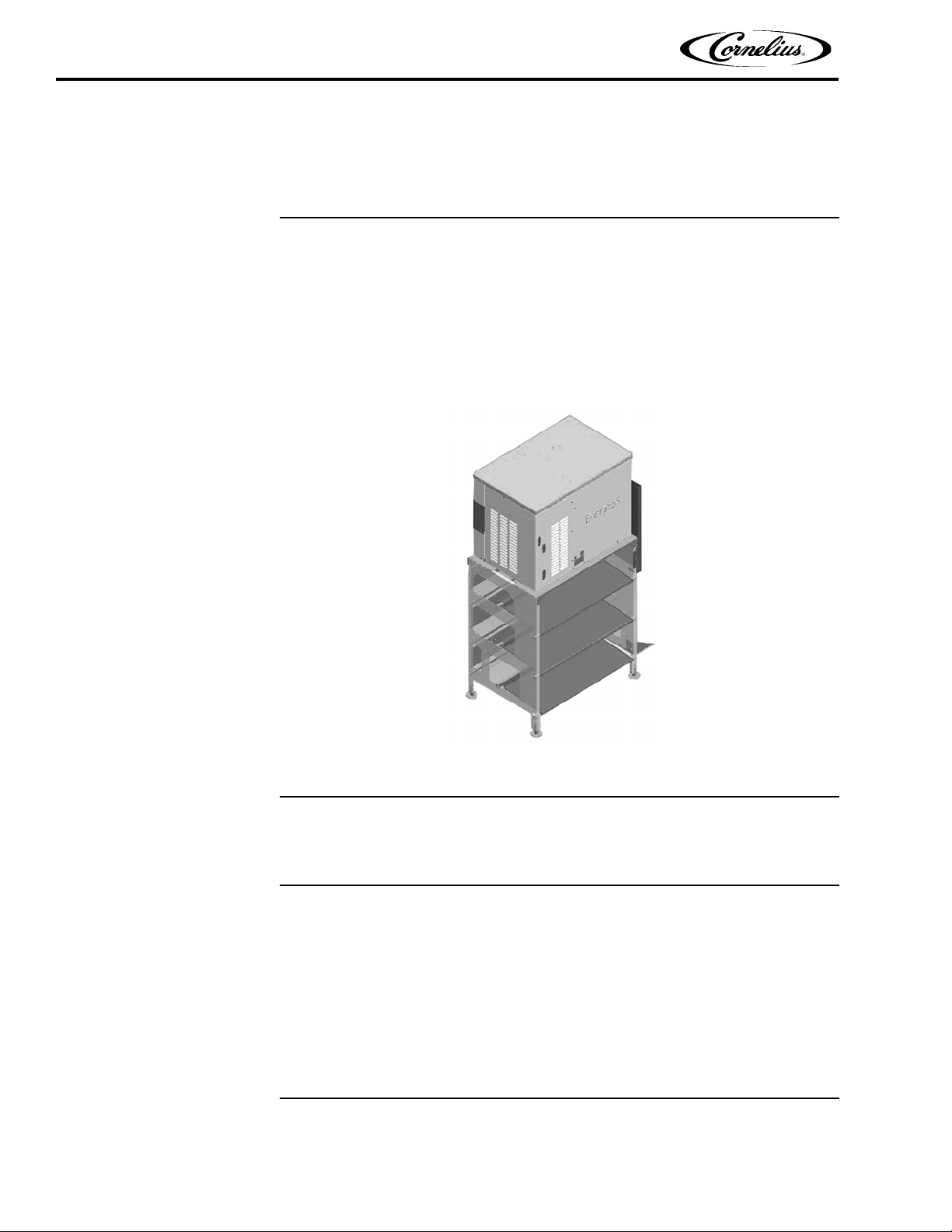
The system consists of the backroom package, the cooler carbonator unit and the
interconnect pythons. These are arranged in a manner similar to Figure 1. Layout
details may vary according to the system location.
Figure 1.
FEATURES
• Environmentally friendly refrigerant - R404a
• Intelligent variable speed recirculation
• Syrup conditioning at the point of dispensing
• Improved water bath insulation for more unit efficiency
• Individual supply shutoffs
• SMART Capable
• Snooze mode
Publication Number: 621058457SER - 4 - © 2012, IMI Cornelius Inc.
Page 9
ENERGY EFFICIENCY
SPECIFICATIONS
Energize6 Service Manual
The cooling liquid in a beverage system takes a significant amount of energy to
maintain, usually using electrical power for this purpose. To keep the need for
energy as low as possible and save costs, the Energize unit decides between dispense times and operational readiness. During operational readiness, for example
overnight, Energize runs in standby mode. All functions are reduced to a minimum
and therefore power consumption is also at a minimum. The Energize system
identifies when drinks are dispensed, automatically switching to maximum power
to supply the required amount of ice. After dispensing, Energize switches back to
standby mode automatically.
Ta bl e 1 .
Model Energize6 USA 220V 60Hz
Continuous Dispense Rate at 75 °F (24 °C)
ambient
Peak Dispense Rate for 2 hours at 75 °F
(24 °C) ambient
Maximum Ambient Condition
Ice bank Weight 110 lbs. (50 kg)
Compressor size 2 HP 2.65 cu in. (43.5 cc)
Refrigerant R404a
Refrigerant charge 14.5 lbs. (6.6 kg)
Tank fill volume (Water Bath) 39 gal. (148 liters)
Compressor run time Start delay 3 min, min run 5 min.
Carbonator size Dual carb with 2 x 3 liter tanks
Pressure switch water inlet
Pressure switch carbonator pump outlet
Voltage 220V 60Hz 3 phase
Height 31.8 in. (810mm)
Depth 27.2 in. (690mm)
Width 42.5 in. (1080mm)
Shipping Weight approx 441 lbs. (200kg)
7 x 12 oz. (355 ml)
10 x 12 oz. (355 ml)
104 °F (40 °C) Unit / 120 °F (49 °C)
Remote Condenser
on >10 psig (0.689 bar) / off <5 psig
(0.345 bar)
ON >145 psig (10 bar) / OFF <130.5 psig
(9 bar)
© 2012, IMI Cornelius Inc. - 5 - Publication Number: 621058457SER
Page 10
Energize6 Service Manual
STARTING THE UNIT
OPERATION
The water bath must be filled up to the overflow with tap water. Refer to the Specifications on page 5 section of this manual for the amount of water required. To prevent
algae from forming in the water a mild disinfectant may be added to the solution.
To fill the unit, perform the procedure in Table 2.
Ta bl e 2 .
Step Action
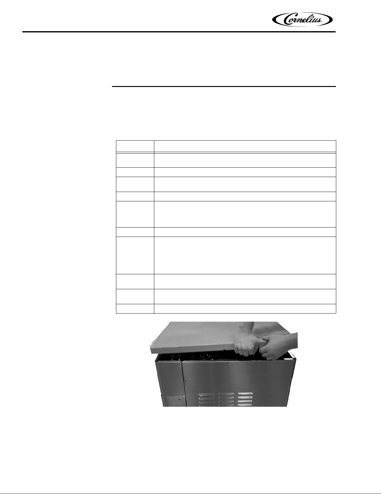
1
2 Lift the cover up, as shown in Figure 2 and store it in a safe place.
3
4 Fill the water bath to the top of the drain pipe, as shown in Figure 5.
5
6 The unit will start to build an ice bank. (approx. 2.5 hrs @ 75 °F)
7
8
9
10 Replace the cover on the unit.
To fill the water bath loosen the screw on the left end of the unit and
remove the cover.
Open the fill valve, located near the right rear corner (near the tubing
entrance). See Figure 3 and Figure 4.
Remove the front access panel (See Service Access on page 18) and
turn on the compressor by moving the compressor switch on the master
controller to the ON position, as shown in Figure 7. The compressor
should start and begin to cool after a 3 to 5 minute time delay.
Turn on the carbonator pump motors by moving the carbonator pump
switches to the ON position. (see Figure 7.)
If the water inlet pressure is within specifications, the carbonator pump
fills the carbonator and then switches off when the upper fill level is
reached. The carbonator tanks are located inside the water bath, as
shown in Figure 8 and Figure 9 on page 9.
Bleed air out of the carbonators and the dispensers by pulling up on the
ring attached to each relief valve, as shown in Figure 10.
Do not turn on the recirculation switches (Figure 7) until ice starts to form
on the evaporator coils.
Figure 2.
Publication Number: 621058457SER - 6 - © 2012, IMI Cornelius Inc.
Page 11
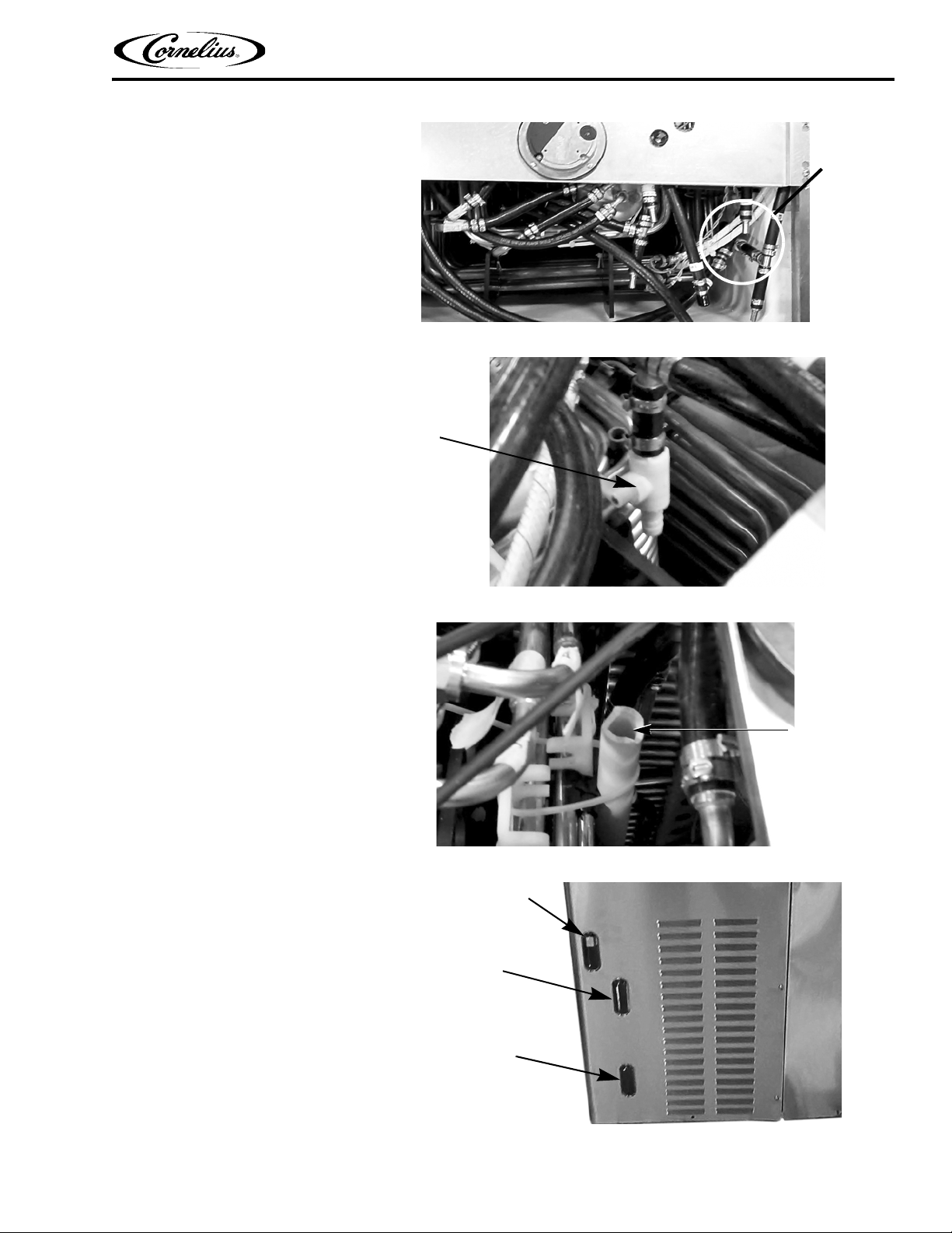
Figure 3.
Water
Fill Valve
Fill Valve
Top of
Drain
Pipe
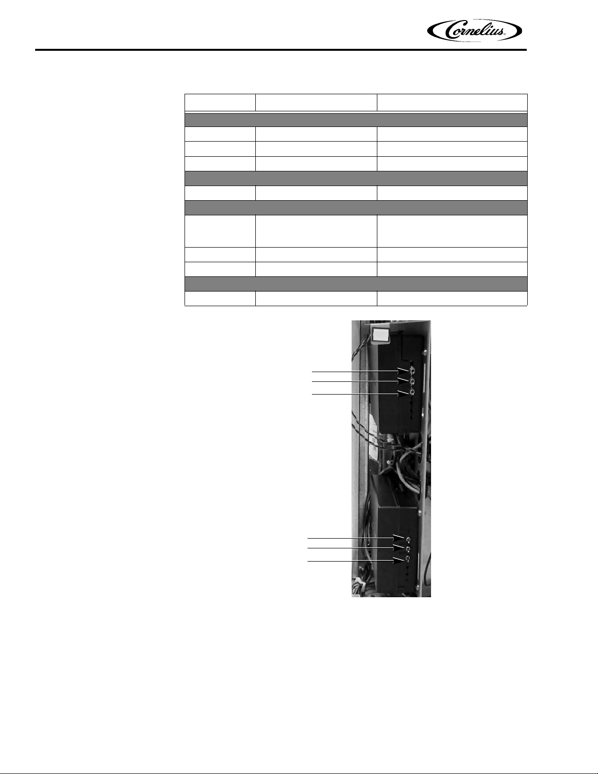
Main Controller
Slave Controller
Indicator Light
Energize6 Service Manual
Figure 4.
Figure 5.
© 2012, IMI Cornelius Inc. - 7 - Publication Number: 621058457SER
Figure 6.
Page 12
Energize6 Service Manual
Compressor
Recirculation
Carbonator Tanks
(Not Used)
Recirculation
Carbonator Tanks
Master Controller
Slave Controller
Ta bl e 3 .
LED Warning Required Action
Green
ON Voltage OK None
OFF No Power Check/Reset Power
Blinks HIGH or LOW Voltage Check/Reset Power
Ye l l o w
ON CO
Red
ON
or
Blinks Slow
Blinks Fast Over Temp/Motion Controller Check/Reset Power
Red/Green
Red/Green
Blinks Main Controller Call Service
2 Pressure Low Check/Replace CO2 Supply
Time Out Carbonator
Water Supply Pressure Low
Reset Power, If it Remains On, Call
Service
Check/Replace Water Filter
Figure 7.
Publication Number: 621058457SER - 8 - © 2012, IMI Cornelius Inc.
Page 13
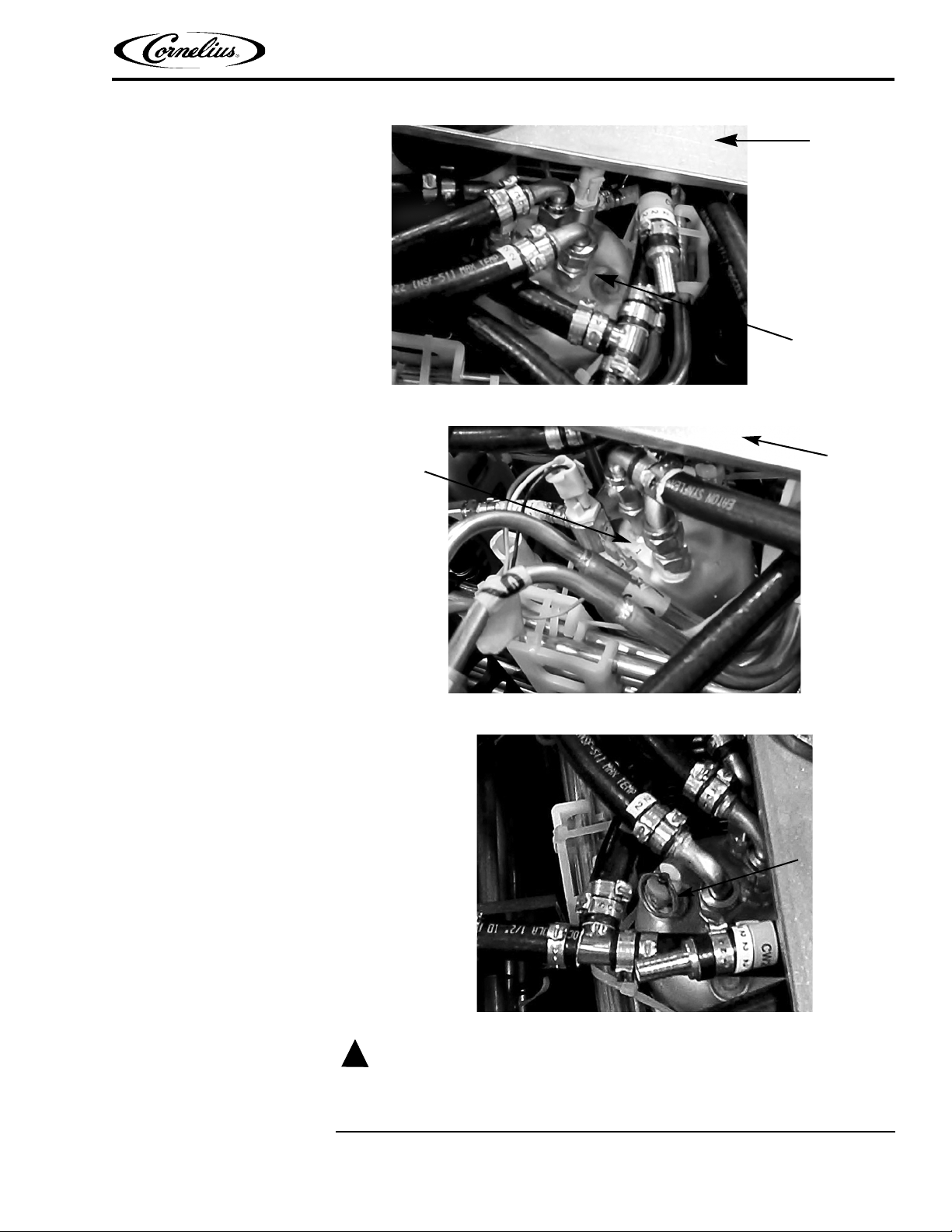
Figure 8.
CAUTION:
!
Agitator
Mounting
Bracket
Carbonator 2
Agitator
Mounting
Bracket
Carbonator 1
Relief Valve
Energize6 Service Manual
Figure 9.
The circulation pump runs even if there is no water in the soda circuit. Running the
Figure 10.
pumps dry damages the soda recirculation pump.
© 2012, IMI Cornelius Inc. - 9 - Publication Number: 621058457SER
Page 14

Energize6 Service Manual
ENDING OPERATION
To prevent loss or health hazard in the event of a leak, the CO2 supply and water
supply lines should be turned off when the system is not in use for a extended
period of time.
Publication Number: 621058457SER - 10 - © 2012, IMI Cornelius Inc.
Page 15
PREVENTIVE MAINTENANCE
!
WARNING:
Only trained and certified electrical, plumbing and refrigeration technicians should
service this unit.
ALL WIRING AND PLUMBING MUST CONFORM TO NATIONAL AND LOCAL
CODES. FAILURE TO COMPLY COULD RESULT IN SERIOUS INJURY, DEATH
OR EQUIPMENT DAMAGE.
CLEANING AND SANITIZING
Changing to a Different Flavor
DAILY
Energize6 Service Manual
• Clean and sanitize the syrup system, as described in “Cleaning and Sanitizing the Syrup System” on page 15.
Daily Inspection
WEEKLY
Cleaning and Sanitizing the Quick Disconnect Fittings
• Check CO2 and water supply.
• Visually check the beverage/syrup lines for
a service technician.
• Check overflow drain connection on the bottom of the unit and the floor
drain.
To clean and sanitize the BIB quick disconnect fittings, perform the procedure in
Ta bl e 4 .
leaks. If leaks are noted, call
© 2012, IMI Cornelius Inc. - 11 - Publication Number: 621058457SER
Page 16
Energize6 Service Manual
Ta bl e 4 .
Step Action
1 Remove all the quick disconnects from all the B-I-B containers.
2 Fill a 1-gallon bucket with mild detergent solution.
3
4 Using a plastic pail, prepare approximately five (5) gallons of sanitizing solution.
5 Rinse the B-I-B disconnects in the sanitizing solution.
6
Submerge all disconnects in the soap solution and then clean them using a
nylon bristle brush. (Do not use a wire brush). Rinse them with clean water.
Repeat Steps 1-5 for all BIB connectors on the rack. Discard the remaining
water from the bucket.
QUARTERLY
Beverage Tubing • Inspect beverage tubing for damage. Re-insulate and seal any uninsu-
lated or damaged tubing.
• Inspect python channels and seal any
• Inspect and clean the grills and condenser fins located on the remote
condenser
, if necessary.
open channel ends.
Water Filters
Syrup Supply
• Verify that water pressure is between 20 psi (1,4 bar) and 120 psi (8,3
bar). If the pressure is low, inspect the water filter cartridges to ensure
that they are able to supply adequate water pressure under normal sys
tem flow. Replace them if they are unable to provide the minimum pressure under load.
• If equipped with a water regulator, verify that it is set to 55 psi (3,8 bar).
Adjust the
setting as
needed.
The syrup supplies should be inspected and cleaned using the procedure in Table 5.
Ta bl e 5 .
Step Action
1
2 Disconnect and remove the syrup containers.
3 Clean the connectors with soap and warm water. Rinse them with plain water.
4 Return the syrup containers and reconnect them.
Inspect syrup lines for the proper flavor identification labels. Replace the labels
as needed.
-
Publication Number: 621058457SER - 12 - © 2012, IMI Cornelius Inc.
Page 17

CO2 Gas Supply
!
DANGER:
!
WARNING:
Energize6 Service Manual
CO2 displaces oxygen. Strict attention MUST be observed in the prevention of CO2
gas leaks in the entire CO
particularly in a small area, IMMEDIATELY ventilate the contaminated area before
attempting to repair the leak. Personnel exposed to high concentrations of CO
experience tremors which are followed rapidly by loss of consciousness and
DEATH.
The CO
Ta bl e 6 .
2 system should be inspected and adjusted according to the procedure in
Step Action
2 and soft drink system. If a CO2 gas leak is suspected,
2 gas
Ta bl e 6 .
ANNUALLY
Water Bath
1
2
3 Verify a proper pressure setting for the syrup pressure regulators.
4
5
The water bath should be inspected and cleaned at least once a year. Perform the
procedure in Table 7 to inspect the water bath.
Step Action
Verify a CO2 high pressure regulator setting of 100 psi (6,8 bar).
Adjust the high pressure regulator, if necessary to obtain the correct pressure
settings.
Adjust the syrup pressure regulators, if necessary to obtain the correct pressure settings.
Inspect the CO2 system for leaks, and repair as needed.
Ta bl e 7 .
1
2
3 If the water bath is clean, replace the unit cover.
If the water bath needs to be cleaned, perform the procedure in Table 8.
Disconnect power to the unit before servicing. Follow all lock out/tag out procedures
established by the user. Verify all power is off to the unit before performing any work.
Remove the cover using the procedure in “Removing the Unit Cover” on
page 14.
Use a flashlight or service light to inspect the water and ice for clarity, particles
and any algae growth.
Failure to comply could result in serious injury, death or damage
to the equipment.
© 2012, IMI Cornelius Inc. - 13 - Publication Number: 621058457SER
Page 18

Energize6 Service Manual
Ta bl e 8 .
Step Action
1 Turn off the electrical supply to the unit.
2 Turn off the water supply to the unit.
3
4 Drain the system by opening a dispense valve.
5 Empty the water bath by removing the overflow tube from the unit.
6
7
8 Fill the bath with a 200ppm chlorinated sanitizing solution.
9 Reconnect the electrical supply to the unit.
10 Turn on the agitator and allow it to run for 10 minutes.
11 Turn off the agitator.
12 Drain all of the sanitizing solution from the water bath.
13
14
15
16 Check the drain to make sure the overflow tube is not leaking.
17 Turn on the CO
18 Replace the cover on the unit.
Remove the cover using the procedure in “Removing the Unit Cover” on
page 14.
Thaw the ice bank. This can be accelerated by pouring warm water into the
water bath.
Carefully spray down the interior of the water bath, the ice coils and the product coils, if dirty.
Thoroughly rinse the bath, the ice coils and the product coils with the same
sprayer as used in Step 8.
Replace the overflow tube, being careful to lubricate the O-rings on the bottom
of the tube with water.
Turn the water supply on and refill the water bath up to the bottom of the overflow opening. See “Starting the Unit” on page 6.
2 supply to the unit.
SERVICE ACCESS
The following procedures describe how to service various subsystems and components of the Energize6 system.
Removing the Unit
Cover
To remove the top cover from the unit, perform the procedure in Table 9.
Ta bl e 9 .
Step Action
1
2 Lift the cover up, as shown in Figure 11, and store it in a safe place.
Publication Number: 621058457SER - 14 - © 2012, IMI Cornelius Inc.
Loosen the screw on the left end of the unit, shown in Figure 11.
Page 19

CLEANING AND SANITIZING THE SYRUP SYSTEM
Cover
Attaching
Screw
To effectively clean and sanitize the syrup lines, a two-step process must be used.
This two-step process includes: Cleaning the system with a cleaner solution, and
rinsing it with water, then sanitizing the system with sanitizer.
Materials required:
• 15 gallons of sanitizing solution (Kay-5 or equivalent - 200 ppm)
Energize6 Service Manual
Figure 11.
Cleaning/Sanitizing
the BIB Backroom
Package
Cleaning and Sanitizing the Quick Disconnect Fittings
• One gallon of mild detergent solution
• Sanitizing fittings or B-I-B end fittings
• One 1-gallon pail (minimum)
• One 5-gallon pail (minimum)
• One nylon brush
Weekly cleaning and sanitizing is recommended for the BIB system.
To clean and sanitize the BIB quick disconnect fittings, perform the procedure in Table
10.
Table 10.
Step Action
1 Remove all the quick disconnects from all the B-I-B containers.
2 Fill a 1-gallon bucket with mild detergent solution.
3
4 Using a plastic pail, prepare approximately five (5) gallons of sanitizing solution.
© 2012, IMI Cornelius Inc. - 15 - Publication Number: 621058457SER
Submerge all disconnects in the soap solution and then clean them using a
nylon bristle brush. (Do not use a wire brush). Rinse them with clean water.
Page 20

Energize6 Service Manual
Cleaning and Sanitizing Procedure
Table 10.
Step Action
5 Rinse the B-I-B disconnects in the sanitizing solution.
6
Repeat Steps 1-5 for all BIB connectors on the rack. Discard the remaining
water from the bucket.
To clean and sanitize the system, perform the procedure in Table 11.
Table 11.
Step Action
Thawing the Ice
Bank
1
2
3
4 Allow sanitizer to remain in the lines for fifteen (15) minutes.
5
6
In a 5-gallon container, mix 5 gallons of sanitizing/cleaning solution to manufacturer’s instructions.
Sanitizing fittings must be attached to each B-I-B disconnect. If these fittings
are not available, the fittings from empty B-I-B bags can be cut from the bags
and used for this purpose. These fittings open the disconnect so the sanitizing
solution can be drawn through the disconnect.
Place all the B-I-B disconnects into the pail of sanitizing solution. Open each
dispenser valve until the sanitizing solution is flowing from the valve.
Remove the nozzle and syrup diffuser from each valve (if equipped) and clean
them in a mild detergent solution. Rinse with clean water and reassemble the
nozzle and syrup diffuser to the valve.
Remove the sanitizing fittings from the B-I-B disconnects and connect the disconnects to the appropriate B-I-B container. Open the valves and let syrup flow
until all sanitizer has been flushed from the system and syrup is flowing freely.
If the unit becomes frozen, it must be carefully Thawed by trained personnel. To
Thaw the Energize6 unit, perform the procedure in Table 12.
Table 12.
Step Action
1 Turn off the electrical supply to the unit.
2 Turn off the water supply to the unit.
3
4 Drain the bath by removing the overflow tube from the unit.
5
6
7
8 Check the drain to make sure the overflow tube is not leaking.
Publication Number: 621058457SER - 16 - © 2012, IMI Cornelius Inc.
Remove the cover using the procedure in “Removing the Unit Cover” on
page 14.
Thaw the ice bank. This can be accelerated by pouring warm water into the
water bath.
Replace the overflow tube, being careful to lubricate the O-rings on the bottom
of the tube with water before inserting it into the drain.
Turn the water supply on and refill the water bath up to the bottom of the overflow opening.
Page 21

Table 12.
Step Action
9 Replace the cover on the unit.
10 Turn on the electrical supply to the unit.
Energize6 Service Manual
© 2012, IMI Cornelius Inc. - 17 - Publication Number: 621058457SER
Page 22

Energize6 Service Manual
!
WARNING:
!
WARNING:
CAUTION:
!
COMPONENT SERVICE
Only trained and certified electrical, plumbing and refrigeration technicians should
service this unit.
ALL WIRING AND PLUMBING MUST CONFORM TO NATIONAL AND LOCAL
CODES. FAILURE TO COMPLY COULD RESULT IN SERIOUS INJURY, DEATH
OR EQUIPMENT DAMAGE.
Disconnect power to the unit before servicing. Follow all lock out/tag out procedures
established by the user. Verify all power is off to the unit before performing any work.
Failure to comply could result in serious injury, death or damage
to the equipment.
All of the threaded plumbing connections in the system contain a plastic gasket to
ensure a proper seal when the connection is tightened. MAKE SURE TO REPLACE
THIS GASKET WHENEVER A CONNECTION IS OPENED FOR REPAIR.
SERVICE ACCESS
Main Service Panel
The following procedures describes how to access portions of the unit under the
main service panel.
To remove the main service panel, perform the procedure in Table 13.
Table 13.
Step Action this
1
2
3 Lift the service panel away from the base of the Energize6 unit.
Remove the cover using the procedure in "Removing the Unit Cover" on
page 14.
Using a Phillips screwdriver, remove the seven screws around the edges of
the service panel, shown in Figure 12 and Figure 13.
Publication Number: 621058457SER - 18 - © 2012, IMI Cornelius Inc.
Page 23

Figure 12.
Front
Panel
Screws
Access
Side
Panel
Screws
Access
Energize6 Service Manual
Figure 13.
REPLACING RECIRCULATING PUMP COMPONENTS
Replacing a Recirculating Pump
To remove and replace a recirculating pump, perform the procedure in Table 14.
Step Action
1 Determine which carbonator pump is malfunctioning.
2 Turn off the electrical supply to the unit.
3
4 Turn off the appropriate recirculating shutoff valves, shown in Figure 15.
© 2012, IMI Cornelius Inc. - 19 - Publication Number: 621058457SER
Remove the cover using the procedure in “Removing the Unit Cover” on
page 14.
Ta bl e 1 4 .
Page 24

Energize6 Service Manual
Circuit 1
Val ves
Circuit 2
Shutoff
Shut off
Valves
Ta bl e 1 4 .
Step Action
5 Peel back the insulation on the pump tubing, shown in Figure 16.
6 Remove the inlet and outlet plumbing from the pump, as shown in Figure 17.
7
8 Loosen the retaining collar, shown in Figure 18.
9 Remove the recirculating pump assembly by pulling it away from the motor.
10
11 Reinstall the insulation around the pump and over the pump tubing.
12
13
14
15 Open the appropriate recirculating shutoff valves, shown in Figure 15.
16 Turn on the CO
17 Turn on the electrical supply to the unit.
18 Turn on the water supply to the unit.
19 When the unit is refilled, replace the unit cover.
Carefully cut the tape holding the two halves of the insulation together
around the recirculating pump. (See Figure 17.) Save the insulation.
Install the new recirculating pump assembly onto the motor and tighten the
pump retaining collar.
Check and replace the gasket inside the fittings, shown in Figure 14, before
reconnecting the pump.
Reconnect the inlet and outlet plumbing to the pump, using teflon tape to
insure a proper seal.
Turn the water supply on and make sure the water bath level is up to the
notch in the overflow tube.
2 supply to the unit and check the system for leaks.
Figure 14.
Figure 15.
Publication Number: 621058457SER - 20 - © 2012, IMI Cornelius Inc.
Page 25

Figure 16.
Recirculating
Pump
Tubing
Insulation
Recirculating
Pump
Connections
Insulation
Recirculating
Pump
Retaining
Collar
Energize6 Service Manual
Figure 17.
Figure 18.
© 2012, IMI Cornelius Inc. - 21 - Publication Number: 621058457SER
Page 26

Energize6 Service Manual
Motor Ground
Motor Wiring to
Control Box
Motor
Mounting
Bolts
Replacing a Recirculating Pump
Motor
To remove and replace a recirculating pump motor, perform the procedure in Table 15.
Ta bl e 1 5 .
Step Action
1 Determine which recirculating pump motor is malfunctioning.
2 Turn off the electrical supply to the unit.
3
4
5
6 Remove the ground wire from the chassis, shown in Figure 19.
7 Remove the pump retaining collar, shown in Figure 18.
8 Remove the pump from the motor by pulling it away from the motor.
9
10 Install the new recirculating pump motor.
11
12
13 Turn on the CO2 supply to the unit and check the system for leaks.
14 Turn on the electrical supply to the unit.
15 Replace the unit cover.
Remove the cover using the procedure in “Removing the Unit Cover” on
page 14.
Remove the main service panel, using the procedure in “Main Service
Panel” on page 18.
Unplug the connector from the carbonator pump motor, located in the control box.
TIP: Once all tie wraps have been removed, tie a length of string to the
connector before pulling it out of the control board. Then pull the wiring out
of the unit and untie the string. Use the string to fish the new wiring back
through the unit to the control box.
Using the proper size wrench, remove the pump mounting bolts, shown in Figure 20 and slide the motor out of the mounting bracket, shown in Figure 21.
Reconnect the electrical connection from the carbonator pump motor to
the control box.
Turn the water supply on and make sure the water bath is up to the notch in
the overflow tube.
Figure 19
Figure 20.
Publication Number: 621058457SER - 22 - © 2012, IMI Cornelius Inc.
Page 27

REPLACING CARBONATOR PUMP COMPONENTS
Motor
Bracket
Mounting
Energize6 Service Manual
Figure 21.
Replacing a Carbonator Pump
To remove and replace the recirculating pump, perform the procedure in Table 16.
Ta bl e 1 6 .
Step Action
1 Determine which recirculating pump is malfunctioning.
2 Turn off the electrical supply to the unit.
3
4 Drain the system pressure by opening a dispense valve.
5 Turn off the recirculating shutoffs, shown in Figure 22.
6 Label and remove the pressure sensor wires, shown in Figure 24.
7 Remove the pressure sensors from the pump body.
8
9 Loosen the retaining collar, shown in Figure 25.
10 Remove the recirculating pump assembly by pulling it away from the motor.
11
12
13
14
15 Connect the pressure sensor wires to the appropriate sensor.
16
Remove the cover using the procedure in “Removing the Unit Cover” on
page 14.
Remove the high and low pressure plumbing connectors from the pump,
shown in Figure 23.
Install the new recirculating pump assembly onto the motor and tighten the
pump retaining collar.
Check and replace the gasket inside the fittings, shown in Figure 14 on
page 20, before reconnecting the inlet and outlet plumbing.
Reconnect the inlet and outlet plumbing to the pump, using teflon tape to
insure a proper seal.
Insert the pressure sensors into the new pump, using teflon tape to insure
a proper seal.
Turn the water supply on and make sure the water bath level is up to the
notch in the overflow tube.
© 2012, IMI Cornelius Inc. - 23 - Publication Number: 621058457SER
Page 28

Energize6 Service Manual
Carbonator
Shutoff
Val ve s
Low Pressure
Pump
Connection
Carbonator
High Pressure
Pump
Connection
Carbonator
Ta bl e 1 6 .
Step Action
17 Open the recirculating shutoffs, shown in Figure 22.
18 Turn on the CO
19 Turn on the electrical supply to the unit.
20 Replace the unit cover.
2 supply to the unit and check the system for leaks.
Figure 22.
Figure 23.
Publication Number: 621058457SER - 24 - © 2012, IMI Cornelius Inc.
Page 29

Figure 24.
Pressure
Sensors
Retaining
Collar
Energize6 Service Manual
Replacing a Carbonator Pump Motor
Figure 25.
To remove and replace a carbonator pump motor, perform the procedure in Table 17.
Ta bl e 1 7 .
Step Action
1 Turn off the electrical supply to the unit.
2 Remove the cover using the procedure in “Removing the Unit Cover” on page 14.
Unplug the connector from the control box, making sure to remove any tie
wraps holding the wiring in place.
3
4 Remove the ground wire from the chassis as shown in Figure 19 on page 22.
5 Remove the pump retaining collar, shown in Figure 25.
6 Remove the pump from the motor by pulling it away from the motor.
7 Install the new carbonator pump motor.
8 Replace the electrical connection from the recirculating pump to the control box.
9
TIP: Once all tie wraps have been removed, tie a length of string to the
connector before pulling it out of the control board. Then pull the wiring out
of the unit and untie the string. Use the string to fish the new wiring back
through the unit to the control box.
Turn the water supply on and make sure the water bath level is up to the
notch in the overflow tube.
© 2012, IMI Cornelius Inc. - 25 - Publication Number: 621058457SER
Page 30

Energize6 Service Manual
Agitator Motor
Mounting
Bracket
Tie Wrap
Replacing Carbonator Pump Pressure
Switch
es
Ta bl e 1 7 .
Step Action
10 Turn on the CO2 supply to the unit and check the system for leaks.
11 Turn on the electrical supply to the unit.
12 Replace the unit cover.
To replace the carbonator pressure switches, perform the procedure in Table 18.
Ta bl e 1 8 .
Step Action
1 Turn off the electrical supply to the unit.
2 Remove the cover using the procedure in “Removing the Unit Cover” on page 14.
3 Drain the system pressure by opening a dispense valve.
4 Turn off the carbonator shutoffs, shown in Figure 22.
5
6 Remove the malfunctioning pressure switch.
7
8 Connect the pressure switch wires to the appropriate switch.
9
10 Open the carbonator shutoffs, shown in Figure 22.
11 Turn on the CO
12 Turn on the electrical supply to the unit.
13 Replace the unit cover.
Label and remove the pressure switch wires on the sensor being replaced,
shown in Figure 24.
Insert the new pressure switch into the pump, using teflon tape to insure a
proper seal.
Turn the water supply on and make sure the water bath level is up to the
notch in the overflow tube.
2 supply to the unit and check the system for leaks.
REPLACING THE AGITATOR MOTOR
The agitator motor is mounted on the top of the unit, on a mounting bracket, shown
in Figure 26.
Figure 26.
To remove and replace the agitator motor, perform the procedure in Table 19.
Publication Number: 621058457SER - 26 - © 2012, IMI Cornelius Inc.
Page 31

Energize6 Service Manual
Bracket
Mounting
Screws
Impeller
Splash Guard
Slinger
Agitator
Motor
Ta bl e 1 9 .
Step Action
1 Turn off the electrical supply to the unit.
2 Remove the cover using the procedure in “Removing the Unit Cover” on page 14.
Unplug the two connectors from the control box, making sure to remove
any tie wraps holding the wiring in place.
3
4
5
6 Carefully slide the bracket and remove it.
7
8 Remove the slinger off the end of the motor shaft.
9
10 Remove the splash guard from the motor, shown in Figure 28.
11 Install the splash guard onto the new motor.
12
13
14 Install the agitator bracket assembly back onto the unit.
15 Replace the electrical connections from the agitator motor to the control box.
16 Turn on the electrical supply to the unit.
17 Replace the unit cover.
TIP: Once all tie wraps have been removed, tie a length of string to the
connector before pulling it out of the control board. Then pull the wiring out
of the unit and untie the string. Use the string to fish the new wiring back
through the unit to the control box.
Remove the tie wrap holding the pressure sensor wires to the agitator
motor bracket, shown in Figure 26.
Loosen the four screws (two on each side) holding the agitator bracket to
the unit, shown in Figure 27.
Place the bracket and pump assembly on a workbench or table and
unscrew the impeller blade from the shaft, shown in Figure 28.
Remove the four screws and nuts holding the agitator motor to the mounting bracket, shown in Figure 29.
Replace the slinger on the motor shaft and reinstall the impeller blade on
the end of the motor shaft.
Mount the motor assembly back onto the mounting bracket using the four
screws and nuts.
Figure 27.
© 2012, IMI Cornelius Inc. - 27 - Publication Number: 621058457SER
Figure 28.
Page 32

Energize6 Service Manual
Mounting
Screws
Mounting
Screws
REPLACING THE ELECTRONIC ICE PROBE
The electronic ice probe is located in the water bath near the center rear of the unit
To remove and replace the electronic ice probe, perform the procedure in Table 20.
Figure 29.
Ta bl e 2 0 .
Step Action
1 Turn off the electrical supply to the unit.
2 Remove the cover using the procedure in “Removing the Unit Cover” on page 14
3
4
5
6
7 Remove the tie wrap from the assembly.
8 Install a new tie wrap to retain the probe to the support clip.
9 Install the assembly back into the water bath.
10
11
12 Turn on the electrical supply to the unit.
13 When the unit is refilled, replace the unit cover.
Lower the water level of the water bath by removing the overflow tube from
the unit.
Thaw the ice bank. This can be accelerated by pouring warm water into the
water bath.
Unplug the connector from the control box, making sure to remove any tie
wraps holding the wiring in place.
TIP: Once all tie wraps have been removed, tie a length of string to the
connector before pulling it out of the control board. Then pull the wiring out
of the unit and untie the string. Use the string to fish the new wiring back
through the unit to the control box.
Unsnap the ice probe from the evaporator coil and lift the assembly up
and out of the water bath, shown in Figure 30 and Figure 31.
Replace the overflow tube, if removed, being careful to lubricate the Orings on the bottom of the tube with water before inserting it into the drain.
Reconnect the connector to the control box and replace the cable ties to
keep the wiring away from any hot areas of the unit.
Publication Number: 621058457SER - 28 - © 2012, IMI Cornelius Inc.
Page 33

Figure 30.
Ice Probe
Assembly
Energize6 Service Manual
REPLACING THE CARBONATORS
There are two carbonators in the Energize6 unit. To replace a carbonator, perform
the procedure in Table 21.
Step Action
1 Determine which carbonator is malfunctioning.
2 Turn off the electrical supply to the unit.
3 Turn off the water supply to the unit.
4 Turn off the CO
5 Remove the cover using the procedure in “Removing the Unit Cover” on page 14
6 Drain the bath by removing the overflow tube from the unit.
7
8 Drain the system pressure by opening a dispense valve.
9
10 Carefully slide the bracket out of the way.
11
Figure 31.
Ta bl e 2 1 .
2 supply to the unit.
Thaw the ice bank. This can be accelerated by pouring warm water into the
water bath.
To gain access to the carbonator tank, remove the agitator bracket from the
unit, as shown in “Replacing the Agitator Motor” on page 26.
Open the carbonator relief valves and depressurize the carbonators,
shown in Figure 32.
© 2012, IMI Cornelius Inc. - 29 - Publication Number: 621058457SER
Page 34

Energize6 Service Manual
Connector
Carbonator
Relief
Plumbing
Connections
Ground
Wire
Valve
O-Ring
Ta bl e 2 1 .
Step Action
12
13
Unplug the connector and remove the ground wire from the top of the carbonator, shown in Figure 32.
Label and remove the high and low pressure plumbing connectors from the
carbonator, shown in Figure 32.
14 Remove the carbonator from the unit by pulling it straight up out of its mount.
15
16
Remove the carbonator tank probe, shown in Figure 33, by unscrewing it
from the carbonator.
Place the probe into the new carbonator, making sure that the o-ring seal is
in place on the probe.
17 Slide the carbonator into the mount in the unit.
18
19
Check and replace the gasket inside the fittings, shown in Figure 14 on
page 20, before reconnecting the carbonator plumbing.
Reinstall the plumbing connectors to the carbonator, using teflon tape to
insure a proper seal.
20 Reconnect the connector and ground wire to the top of the carbonator.
21 Reinstall the agitator bracket.
22
23
24 Turn on the CO
Replace the overflow tube, being careful to lubricate the O-rings on the bottom of the tube with water before inserting it into the drain.
Turn the water supply on and make sure the water bath level is up to the
notch in the overflow tube. Check the drain for water leaks.
2 supply to the unit and check the system for leaks.
25 Turn on the electrical supply to the unit.
26 When the unit is refilled, replace the unit cover.
Figure 32.
Figure 33.
Publication Number: 621058457SER - 30 - © 2012, IMI Cornelius Inc.
Page 35

REPLACING THE CO2 PRESSURE SWITCHES
CO2
Pressure
Switches
There are two CO2 pressure switches in the Energize6 unit. One for Circuit 1 and
one for Circuit 2. If one of the pressure switches needs to be replaced, perform the
procedure in Table 22.
Step Action
1 Determine which pressure switch is malfunctioning.
2 Turn off the electrical supply to the unit.
3 Turn off the CO
4 Remove the cover using the procedure in “Removing the Unit Cover” on page 14.
5 Drain the system pressure by opening a dispense valve.
6 Vent the carbonators by opening the relief valves, shown in Figure 10 on page 9.
7 Label and disconnect the wiring from the pressure switch, shown in Figure 34.
8 Remove the pressure switch.
9 Install the new pressure switch, using teflon tape to insure a proper seal.
10
11 Turn on the CO
12 Turn on the electrical supply to the unit.
13 When the unit is refilled, replace the unit cover.
Replace the overflow tube, if removed, being careful to lubricate the Orings on the bottom of the tube with water before inserting it into the drain.
2 supply to the unit.
2 supply to the unit and check the system for leaks.
Energize6 Service Manual
Ta bl e 2 2 .
Figure 34.
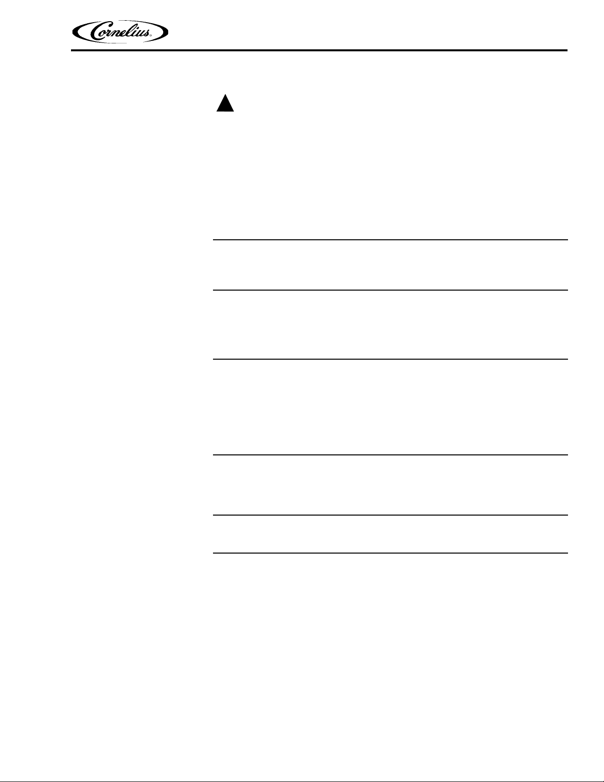
REPLACING THE EXPANSION VALVE ASSEMBLIES
The Energize6 unit has one compressor and two cooling circuits. There are two
expansion valve assemblies to accommodate the two circuits, as shown in Figure
35. The expansion valves are located near the center of the unit, toward the rear. To
replace an expansion valve, perform the procedure in Table 23.
© 2012, IMI Cornelius Inc. - 31 - Publication Number: 621058457SER
Page 36

Energize6 Service Manual
Expansion
Valve Sensor
Bulbs
Expansion
Valves
(under Insulation)
Expansion
Val ves
Sensors
(w/Insulation
removed)
Figure 35.
Ta bl e 2 3 .
Step Action
1 Turn off the electrical supply to the unit.
2 Remove the cover using the procedure in “Removing the Unit Cover” on page 14
3 Reclaim the refrigerant from the system.
4 Carefully unwrap the insulation from around the sensor bulbs.
5
6 Replace the expansion valve and re-install the sensor bulb into the clamp.
7 Replace the insulation around the bulb sensor.
8
9 Evacuate the system.
10
Remove the expansion valve sensor bulb from the clamp holding it to the
refrigerant line, shown in Figure 36.
Replace the filter/dryer, located at the left rear of the unit, as shown in Figure 37.
Restore the proper refrigerant charge to the system and verify proper system operation.
Publication Number: 621058457SER - 32 - © 2012, IMI Cornelius Inc.
Figure 36.
Page 37

HIGH PRESSURE SWITCH REPLACEMENT
Filter/Dryer
Before replacing the high pressure switch, inspect the remote condenser for proper
air flow, any obstructions or a failed fan motor.
The high pressure switch, shown in Figure 38, is located at the left rear of the unit,
behind the access panel. The switch has a reset button. The reset button should be
pressed and the unit restarted before replacing the high pressure switch. If the
switch trips again, replace the switch by performing the procedure in Table 24.
Energize6 Service Manual
Figure 37.
Ta bl e 2 4 .
Step Action
1 Turn off the electrical supply to the unit.
2 Remove the access panel from the rear of the unit.
Unplug the electrical connections from the high pressure switch to the con-
3
4 Reclaim the refrigerant from the system.
5 Replace the high pressure switch.
6
7 Replace the filter/dryer, see Figure 37 on page 33.
8 Evacuate the system.
9
10 Replace the access panel.
trol box. and remove any tie wraps holding the wiring.
TIP: Tie a length of string to the connector before pulling it out of the control board. Then pull the wiring out of the unit and untie the string. Use the
string to fish the new wiring back through the unit to the control box.
Replace the electrical connection from the high pressure switch to the control box.
Restore the proper refrigerant charge to the system and verify proper system operation.
© 2012, IMI Cornelius Inc. - 33 - Publication Number: 621058457SER
Page 38

Energize6 Service Manual
Solenoid
Val ve
High
Pressure
Switch
Reset
Button
Electrical
Connections
REPLACING THE SOLENOID COIL
The solenoid valve, shown in Figure 38, is located at the left rear of the unit, behind
the access panel. To replace the solenoid coil, perform the procedure in Table 25.
Figure 38.
Ta bl e 2 5 .
Step Action
1 Turn off the electrical supply to the unit.
2 Remove the access panel from the rear of the unit.
3 Remove the electrical connections to the solenoid, shown in Figure 39.
4 Pull the solenoid off of the valve stem.
5
6 Reconnect the wiring to the solenoid.
7 Replace the access panel.
8 Turn on the electrical supply to the unit.
Replace the solenoid by pressing the new solenoid onto the valve stem, as
shown in Figure 40.
Figure 39.
Publication Number: 621058457SER - 34 - © 2012, IMI Cornelius Inc.
Page 39

REPLACING THE SOLENOID VALVE BODY
Solenoid
The solenoid valve, shown in Figure 38, is located at the left rear of the unit, behind the
access panel. To replace the solenoid valve body, perform the procedure in Table 26.
Energize6 Service Manual
Figure 40.
Step Action
1 Turn off the electrical supply to the unit.
2 Remove the access panel from the rear of the unit.
3 Remove the solenoid coil from the valve body.
4 Reclaim the refrigerant from the system.
5 Replace the solenoid valve body.
6
7 Replace the filter/dryer, see Figure 37 on page 33.
8 Evacuate the system.
9
10 Replace the access panel.
REPLACING THE HEAD MASTER
The head master is located at the top of the compressor, near the left side of the
unit. To replace the head master, perform the procedure in Table 27.
Step Action
Ta bl e 2 6 .
Replace the solenoid coil by pressing the it onto the valve stem, as shown
in Figure 40.
Restore the proper refrigerant charge to the system and verify proper system operation.
Ta bl e 2 7 .
1 Turn off the electrical supply to the unit.
2 Remove the access panel from the left side of the unit.
3 Drain the bath by removing the overflow tube from the unit.
4
5 Reclaim the refrigerant from the system.
© 2012, IMI Cornelius Inc. - 35 - Publication Number: 621058457SER
Thaw the ice bank. This can be accelerated by pouring warm water into the
water bath.
Page 40

Energize6 Service Manual
Head
Master
Compressor
Ta bl e 2 7 .
Step Action
6 Replace the head master, shown in Figure 41.
7 Replace the filter/dryer, shown in Figure 37 on page 33.
8 Evacuate the system.
9
10 Replace the access panel.
Restore the proper refrigerant charge (shown on the unit nameplate) to the
system and verify proper system operation.
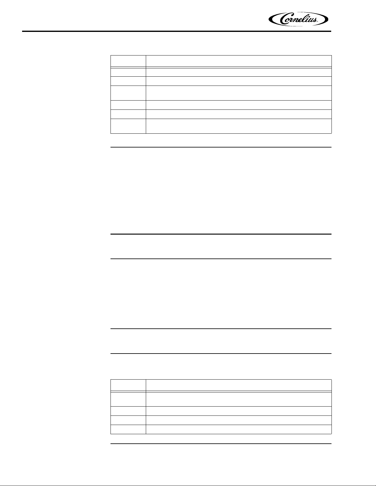
REPLACING THE MESH STRAINER
There is a mesh strainer in each of the output lines from the carbonated water
pumps. Occasionally, one of these strainers may become clogged and require
replacement. To replace the mesh strainer, perform the procedure in Table 28.
Figure 41.
Ta bl e 2 8 .
Step Action
1 Turn off the electrical supply to the unit.
2 Turn off the water supply to the unit.
3 Remove the cover using the procedure in “Removing the Unit Cover” on page 14
4 Drain the system pressure by opening a dispense valve.
5 Vent the carbonators by opening the relief valves, shown in Figure 10 on page 9.
6 Turn off the recirculation shutoffs, shown in Figure 22 on page 24.
7
8 Remove the mesh strainer from the check valve, shown in Figure 42.
9 Install a new mesh strainer, using teflon tape to insure a proper seal.
10
11
12
Remove the high pressure plumbing connector from the pump, shown in
Figure 23 on page 24.
Check and replace the gasket inside the fitting, shown in Figure 14 on
page 20, before reconnecting the outlet plumbing.
Reconnect the outlet plumbing to the pump, using teflon tape to insure a
proper seal.
Replace the overflow tube, being careful to lubricate the O-rings on the bottom of the tube with water before inserting it into the drain.
Publication Number: 621058457SER - 36 - © 2012, IMI Cornelius Inc.
Page 41

Ta bl e 2 8 .
Mesh
Strainer
Check
Valve
Relief
Valve
Step Action
Energize6 Service Manual
13
14 Turn on the electrical supply to the unit.
15 When the unit is refilled, replace the unit cover.
REPLACING THE CHECK VALVE
There is a check valve in back of the mesh strainers in each of the output lines from
the recirculating water pumps. To replace the check valve, perform the procedure in
Ta bl e 2 9 .
Turn the water supply on and make sure the water bath level is up to the
notch in the overflow tube.
Figure 42.
Ta bl e 2 9 .
Step Action
1 Turn off the electrical supply to the unit.
2 Turn off the water supply to the unit.
3 Remove the cover using the procedure in “Removing the Unit Cover” on page 14
4 Drain the system pressure by opening a dispense valve.
5
6 Turn off the recirculation shutoffs, shown in Figure 22 on page 24.
7
8 Remove the check valve, shown in Figure 42.
9 Install a new check valve, using teflon tape to insure a proper seal.
10
11
12 Turn on the electrical supply to the unit.
13 When the unit is refilled, replace the unit cover.
Vent the carbonators by opening the relief valves, shown in Figure 10 on
page 9.
Remove the high pressure plumbing connector from the pump, shown in
Figure 23 on page 24.
Reinstall the plumbing connector to the pump, using teflon tape to insure a
proper seal.
NOTE: Make sure to replace the gasket inside the fitting, when reconnecting the plumbing.
Turn the water supply on and make sure the water bath level is up to the
notch in the overflow tube.
© 2012, IMI Cornelius Inc. - 37 - Publication Number: 621058457SER
Page 42

Energize6 Service Manual
REPLACING THE CONTROLLER BOARDS
The controller boards are located on the front, left side of the unit, under the access
panel. To remove and replace a controller board, perform the procedure in Table 30.
Step Action
1 Turn off the electrical supply to the unit.
2 Remove the cover using the procedure in “Removing the Unit Cover” on page 14
3 Remove the service panel using the procedure in “Service Access” on page 14
4 Remove the cover from the malfunctioning control board, shown in Figure 43.
5 Unplug the connectors from the control board.
6 Install the new control board.
7 Reconnect all the connectors to the control board.
8 Replace the cover on the control board.
9 Turn on the electrical supply to the unit.
10 Replace the unit cover.
Ta bl e 3 0 .
Figure 43.
Publication Number: 621058457SER - 38 - © 2012, IMI Cornelius Inc.
Page 43

Energize6 Service Manual
TROUBLESHOOTING
Before looking for problems with the dispensing equipment, first check the following:
1. Is the power connected to the unit?
2. Is the power switch turned on?
3. Is the water connected to the unit?
4. Is the water filter clogged?
5. Are the beverage containers empty?
6. Is the CO
Seq Symptom Potential Failure Mode Potential Diagnosis Check
1 Warm Drinks System Not Running No Power or Low / High Voltage Check LED - (Green Blinking)
2 Warm Drinks Compressor - Running Insufficient System Capacity
3 Warm Drinks Compressor - Running Low on Charge
4 Warm Drinks Compressor - Not Running Power Switch Off Check Switch Position
5 Warm Drinks Compressor - Not Running Low Water Level
6 Warm Drinks Compressor - Not Running
7 Warm Drinks Compressor - Not Running Condenser Fan Motor Failure
8 Warm Drinks Compressor - Not Running Compressor internal cut out
9 Warm Drinks Compressor - Not Running Compressor Failure
10 Warm Drinks Compressor - Not Running Main Controller Fail Check LED - (R&G Blinking)
1 Warm Drinks Agitator Motor - Not Running Controller Failure
2 Warm Drinks Agitator Motor - Not Running Agitator Motor Failure Replace the motor
2 supply empty?
Condenser Dirty or Partially
Blocked
# of Drinks Served/Hr and python
losses. Python and insulation wet?
Refrigerant Pressures. Check ice
bank form. Ice up to the last winding?
Check Water level. Ice bank probe
must be located below water level
Power to / from refrigerant High
Pressure Switch (check reset)
Start compressor and look if the fan
motor starts as well.
Power to compressor? Check voltage to each leg (120V to ground)
Check start relay and start capacitor
No Power to agitator motor (power
and signal cable connected?)
1 Warm Drinks
2 Warm Drinks
3 Warm Drinks
4 Warm Drinks
No Carb
1
Water
No Carb
2
Water
No Carb
3
Water
© 2012, IMI Cornelius Inc. - 39 - Publication Number: 621058457SER
Recirculation Pump Motor Not Running
Recirculation Pump Motor Not Running
Recirculation Pump Motor Not Running
Recirculation Pump Motor Not Running
Carbonator Pump Motor Running
Carbonator Pump Motor Running
Carbonator Pump Motor - Not
Running
Recirculation Motor Switch Off Power Switch
Motion Controller Failure Power to pump motor
Pump failure or Blocked Power to pump motor
Pump Motor Failure Replace motor
Blocked Filter Screen
Water inlet pressure switch fail
closed
Out of CO2
Pump falls into the 20min max run
time. Power reset required.
Check LED (Yellow) Check CO2
Supply
Page 44

Energize6 Service Manual
Seq Symptom Potential Failure Mode Potential Diagnosis Check
4
5
6
7
8
9
10
11
No Carb
Water
No Carb
Water
No Carb
Water
No Carb
Water
No Carb
Water
No Carb
Water
No Carb
Water
No Carb
Water
Carbonator Pump Motor - Not
Running
Carbonator Pump Motor - Not
Running
Carbonator Pump Motor - Not
Running
Carbonator Pump Motor - Not
Running
Carbonator Pump Motor - Not
Running
Carbonator Pump Motor - Not
Running
Carbonator Pump Motor - Not
Running
Carbonator Pump Motor - Not
Running
Low CO2 Psi Switch fails closed
Low Water Pressure
Water inlet pressure switch fail
open
Short circuit the switch and check if
yellow LED is off
Check LED (Red blnks) check
water pressure
Check water pressure at gauge or
replace switch
Carbonator Level Sensor Shorted Check wiring or replace the probe
Fill Time Out Check LED (Red) - Reset Power
Main Controller Failure Check LED - (R&G Blinking)
Pump Motor Failure Replace motor
Still Water Solenoid fails closed
Check if valve does open or replace
solenoid
1
2
3
4
5
6
7
8
9
10
1
2
3
4
5
Low Carbonation
Low Carbonation
Low Carbonation
Low Carbonation
Low Carbonation
Low Carbonation
Low Carbonation
Low Carbonation
Low Carbonation
Low Carbonation
Agitator
pump
Agitator
pump
Agitator
pump
Agitator
pump
Agitator
pump
Carbonator Pump Motor Running
Carbonator Pump Motor Running
Carbonator Pump Motor Running
Carbonator Pump Motor Running
Carbonator Pump Motor short cycling
Carbonator Pump Motor short cycling
onator Pump Motor -
Carb
short cycling
Carbonator Pump Motor short cycling
Low CO2 Pressure Regulator Setting / Bottle empty
Air in carbonator Bleed Carbonator
Water Temp too high Ice Bank and Water Temp too high
Still Water Solenoid fails open
Low Water pressure
Level control probe and connections
Check if solenoid is closing if still
water is being dispensed
Check red indicator (flashing once
per second)
Check probe location and connections
Unplug probe connector on main
Defective probe
control board, pump should run
continuously
Defective pressure switch on inlet Jumper to test
Unplug corresponding recirculation
Carbonator Pump Motor short cycling
Defective thermistor
control thermistor from correspond-
ing main board. Short cycling stops
if defective
Carbonator Pump Motor short cycling
Defective carbonator pump or
motor
Check pump and motor
Continuously runs hi or lo Water bath temp sensor Test sensor
Continuously runs hi or lo Connections at main controller Check connections
Continuously runs hi or lo Bad agitator motor Check motor
Continuously runs hi or lo Low water level/probe out of water Check probe position
Continuously runs hi or lo Bad main control board Check and replace board
1 Freeze up Compressor running
Publication Number: 621058457SER - 40 - © 2012, IMI Cornelius Inc.
Ice bank probe in wrong bend/
wrong location
Check ice probe position and cor-
rect
Page 45

Energize6 Service Manual
Seq Symptom Potential Failure Mode Potential Diagnosis Check
2 Freeze up Compressor running Ice bank probe not connected
3 Freeze up Compressor running Ice bank probe interrupted Check cable resistance end to end
4 Freeze up Compressor running Controller relay defect Exchange main controller
5 Freeze up Compressor running Agitator motor off Check agitator motor
Irregular Ice
1
2
3
Bank
Irregular Ice
Bank
Irregular Ice
Bank
Ice bank buiding unequally Agitator motor bad Check agitator motor
Ice bank buiding unequally
Water bath overflow tube not
seated
Ice bank buiding unequally TXV sensing bulb mounting bad
Check cable connector on controller side
Check water bath level
Check TXV sensing bulb mounting
(2)
1
2
3
1
2
3
4
5
Water bath
overflows
Water bath
overflows
Water bath
overflows
No recirculation
No recirculation
No recirculation
No recirculation
No recirculation
Water bath continues to overfill
Water bath continues to overfill
Water bath continues to overfill
Recirculation pump not running
Recirculation pump not running
Recirculation pump not running
Recirculation pump not running
Recirculation pump not running
Water bath fill valve not shut off
completely
Stainless steel cooling coil(s) ruptured
Leaking crimped water line connection
Check water bath fill valve
Check coils and replace if necessary
Check crimped water line connections
Defective pump motor Check and replace motor
Defective motor control board Check and replace control board
Motor control board shut down on
error
Loose or defective wire connection
Troubleshoot error
Check and tighten connections
Low voltage Check and verify voltages
© 2012, IMI Cornelius Inc. - 41 - Publication Number: 621058457SER
Page 46

Energize6 Service Manual
FLOW CHARTS AND CIRCUIT DIAGRAMS
PLUMBING DIAGRAM
Publication Number: 621058457SER - 42 - © 2012, IMI Cornelius Inc.
Page 47

Energize6 Service Manual
© 2012, IMI Cornelius Inc. - 43 - Publication Number: 621058457SER
Page 48

Energize6 Service Manual
Publication Number: 621058457SER - 44 - © 2012, IMI Cornelius Inc.
Page 49

WIRING DIAGRAM
Energize6 Service Manual
© 2012, IMI Cornelius Inc. - 45 - Publication Number: 621058457SER
Page 50

Energize6 Service Manual
Publication Number: 621058457SER - 46 - © 2012, IMI Cornelius Inc.
Page 51

Page 52

IMI Cornelius Inc.
www.cornelius.com
 Loading...