

Page 1
ED150-8V “K” Style Lid Kit Installation Instructions
!
WARNING:
!
WARNING:
!
WARNING:
INSTALLATION INSTRUCTIONS
FOR ED150-8V “K” STYLE LID KITS, P/N 630200153 AND 630000191
These “K” style kits apply to the following ice makers:
Table 1. Applicable Models
Ice Maker Width
Cornelius 322/522 22I
Crystal Tips 200/300/400 22”
Ice-O-Matic 22”
Manitowoc 320/420 22”
Scotsman SLC 300/400 22”
Servend S2/4 22”
Table 2. Loose Shipped Parts
Item No. Part No. Name Qty.
1
2 620028801 Lid Assembly 1
3 22127 Bracket 2
4 70217 #8 Screw 12
5 50904 RTV 1
6 90221 Label 1
7 620912201 Installation Instruction 1
8 620701902 Acorn Nut, 8-32 Nylon 2
9 620701901 Sealing Washer 2
10 620037007 Baffle, Ice DF/ED150 1
11 621701903 #8 Nylon Washer 2
12 620505804 Insulation Strip 1
52994 Cover, Gray (630000191) 1
52934 Cover, Black (630200153) 1
Disconnect power to the unit before installing the adaptor following all lockout/tag out procedures established by the
user. Verify that all the power is off to the unit before performing any work.
Failure to comply could result in serious injury, death or damage to the equipment.
All ice baffle plates and bin stats, if included or recommended in this kit, must be installed as directed in this manual or
the equipment manufacturer’s instructions.
Failure to comply could result in serious injury, death or damage to the equipment.
All of the attachment screws and plates must be installed as directed in this manual.
Failure to comply could result in serious injury, death or damage to the equipment.
1. Unpack the kit.
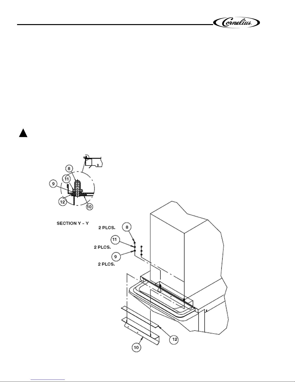
2. Place insulation strip (item 12) over studs on the baffle and Insert baffle assembly into the adapter lid.
3. Place (2) sealing washers (item 9) over studs and (2) flat washers (item11), then fasten in place with (2) plastic
acorn nuts (item 8).
4. Set ice maker lid on the top of the dispenser.
Release Date: November 9, 2010 www.cornelius.com Revision: B
© 1998-2010, IMI Cornelius Inc. - 1 - Publication Number: 620912201
Page 2
ED150-8V “K” Style Lid Kit Installation Instructions
CAUTION:
!
5. Using the slotted holes in the lid as a template, drill four (4) 0.140” diameter (9/64”) holes at the bottom of the slots
(see Detail A). Use extreme care not to drill into the hopper. Fasten the lid to the dispenser with four (4) #8 sheet
metal screws, two on each side.
6. Seal the ice maker to the top of the dispenser as follows:
A. Run beads of RTV around the opening in the lid and inside of the perimeter of the ice maker outline so
that the ice maker sets on the RTV.
B. Set the ice maker onto the lid and position it as required.
C. Wipe away the excess RTV.
7. Drill 9/64I diameter holes into the ice maker cabinet using the bracket as a template. Use extreme care not to drill
into any ice maker components (condenser, tubing, etc.). Secure the brackets using the screws provided
8. Follow the ice maker manufacturers instruction to complete the installation of the ice maker including the bin thermostat if so equipped or required.
9. If the plastic acorn nuts interfere with the positioning of the plastic manual fill cover, it may be necessary to make
small notches in the back flange of the cover to clear the acorn nuts.
Bin Thermostat must not interfere with the agitator rotation.
Publication Number: 620912201 - 2 - © 1998-2010, IMI Cornelius Inc.
Figure 1. ED150-8V Kit
Page 3

ED150-8V “K” Style Lid Kit Installation Instructions
© 1998-2010, IMI Cornelius Inc. - 3 - Publication Number: 620912201
Figure 2. Dispenser Assembly
 Loading...