

Page 1
IMI CORNELIUS REMCOR INC g 500 REGENCY DRIVE g GLENDALE HEIGHTS, IL 60139–2268
Telephone (800) 551–4423 Facsimile (800) 519–4423
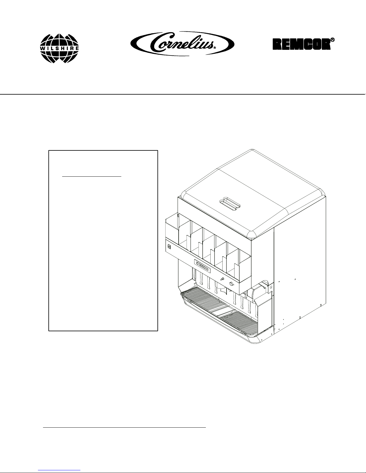
Operator’s Manual
DURAFLEX ICE/BEVERAGE DISPENSER
Model: DF 250 BCP
IMPORTANT:
TO THE INSTALLER.
It is the responsibility of
the Installer to ensure that
the water supply to the
dispensing equipment is
provided with protection
against backflow by an air
gap as defined in
ANSI/ASME A112.1.2-1979;
or an approved vacuum
breaker or other such
method as proved effective
by test.
Water pipe connections
and fixtures directly
connected to a potable
water supply shall be
sized, installed, and
maintained according to
Federal, State, and Local
Codes.
Part No.620919540
Revised: July, 2001
Revision: A
Control Code: A
THIS DOCUMENT CONTAINS IMPORTANT INFORMATION
This Manual must be read and understood before installing or operating this equipment
IMI CORNELIUS INC; 2001
PRINTED IN U.S.A
Page 2

TABLE OF CONTENTS
START-UP AND OPERATING INSTRUCTIONS 3. . . . . . . . . . . . . . . . . . . . . . . . . . . . . . .
ICE PORTIONING SYSTEM OPERATION 3. . . . . . . . . . . . . . . . . . . . . . . . . . . . . . . .
NORMAL OPERATION 4. . . . . . . . . . . . . . . . . . . . . . . . . . . . . . . . . . . . . . . . . . . . . . . . .
CLEAN MODE 4. . . . . . . . . . . . . . . . . . . . . . . . . . . . . . . . . . . . . . . . . . . . . . . . . . . . . . . . .
NORMAL ICE PORTION ADJUSTMENT 4. . . . . . . . . . . . . . . . . . . . . . . . . . . . . . . . . .
EXTRA ICE PORTION ADJUSTMENT 4. . . . . . . . . . . . . . . . . . . . . . . . . . . . . . . . . . .
AGITATION REFILL TIME ADJUSTMENT 5. . . . . . . . . . . . . . . . . . . . . . . . . . . . . . . .
MANUAL ICE DISPENSING OPERATION 5. . . . . . . . . . . . . . . . . . . . . . . . . . . . . . . .
MAINTENANCE 7. . . . . . . . . . . . . . . . . . . . . . . . . . . . . . . . . . . . . . . . . . . . . . . . . . . . . . . . . . .
DAILY (OR AS REQUIRED) 7. . . . . . . . . . . . . . . . . . . . . . . . . . . . . . . . . . . . . . . . . . . .
WEEKLY (OR AS REQUIRED) 7. . . . . . . . . . . . . . . . . . . . . . . . . . . . . . . . . . . . . . . . .
MONTHLY 7. . . . . . . . . . . . . . . . . . . . . . . . . . . . . . . . . . . . . . . . . . . . . . . . . . . . . . . . . . .
CLEANING INSTRUCTIONS 7. . . . . . . . . . . . . . . . . . . . . . . . . . . . . . . . . . . . . . . . . . . .
DISPENSER 7. . . . . . . . . . . . . . . . . . . . . . . . . . . . . . . . . . . . . . . . . . . . . . . . . . . . . . . . . .
BEVERAGE SYSTEM 9. . . . . . . . . . . . . . . . . . . . . . . . . . . . . . . . . . . . . . . . . . . . . . . . . . . . . .
CLEANING 9. . . . . . . . . . . . . . . . . . . . . . . . . . . . . . . . . . . . . . . . . . . . . . . . . . . . . . . . . . . .
CLEANING DISPENSING VALVES 9. . . . . . . . . . . . . . . . . . . . . . . . . . . . . . . . . . . . .
SANITIZING 9. . . . . . . . . . . . . . . . . . . . . . . . . . . . . . . . . . . . . . . . . . . . . . . . . . . . . . . . .
TROUBLESHOOTING 11. . . . . . . . . . . . . . . . . . . . . . . . . . . . . . . . . . . . . . . . . . . . . . . . . . . . . .
Page
BLOWN FUSE OR CIRCUIT BREAKER. 11. . . . . . . . . . . . . . . . . . . . . . . . . . . . . . . . . .
SLUSHY ICE. WATER IN HOPPER 11. . . . . . . . . . . . . . . . . . . . . . . . . . . . . . . . . . . . . .
BEVERAGES DO NOT DISPENSE. 11. . . . . . . . . . . . . . . . . . . . . . . . . . . . . . . . . . . . . .
BEVERAGES TOO SWEET. 11. . . . . . . . . . . . . . . . . . . . . . . . . . . . . . . . . . . . . . . . . . . .
BEVERAGES NOT SWEET ENOUGH. 11. . . . . . . . . . . . . . . . . . . . . . . . . . . . . . . . . . .
BEVERAGES NOT COLD (UNITS WITH BUILD-IN COLD PLATE). 11. . . . . . . . . .
NO ICE DISPENSED FROM ICE PORTION CONTROLLER 12. . . . . . . . . . . . . . . .
NO ICE DISPENSED FROM MANUAL ICE DISPENSE PUSHBUTTON
SWITCH 12. . . . . . . . . . . . . . . . . . . . . . . . . . . . . . . . . . . . . . . . . . . . . . . . . . . . . . . . . . . . . .
ICE DISPENSING DURING AUTOMATIC AGITATION 13. . . . . . . . . . . . . . . . . . . . . .
PARTS LIST 15. . . . . . . . . . . . . . . . . . . . . . . . . . . . . . . . . . . . . . . . . . . . . . . . . . . . . . . . . . . . . .
WARRANTY 16. . . . . . . . . . . . . . . . . . . . . . . . . . . . . . . . . . . . . . . . . . . . . . . . . . . . . . . . . . . . . .
LIST OF FIGURES
FIGURE 1. PARTS IDENTIFICATION 1. . . . . . . . . . . . . . . . . . . . . . . . . . . . . . . . . . . .
FIGURE 2. CUP SIZE LABEL 3. . . . . . . . . . . . . . . . . . . . . . . . . . . . . . . . . . . . . . . . . . .
FIGURE 3. CABINET SECTION EXPLODED VIEW 15. . . . . . . . . . . . . . . . . . . . . . . .
FIGURE 4. ELECTRICAL BOX ASSEMBLY 18. . . . . . . . . . . . . . . . . . . . . . . . . . . . . . .
i
Page 3
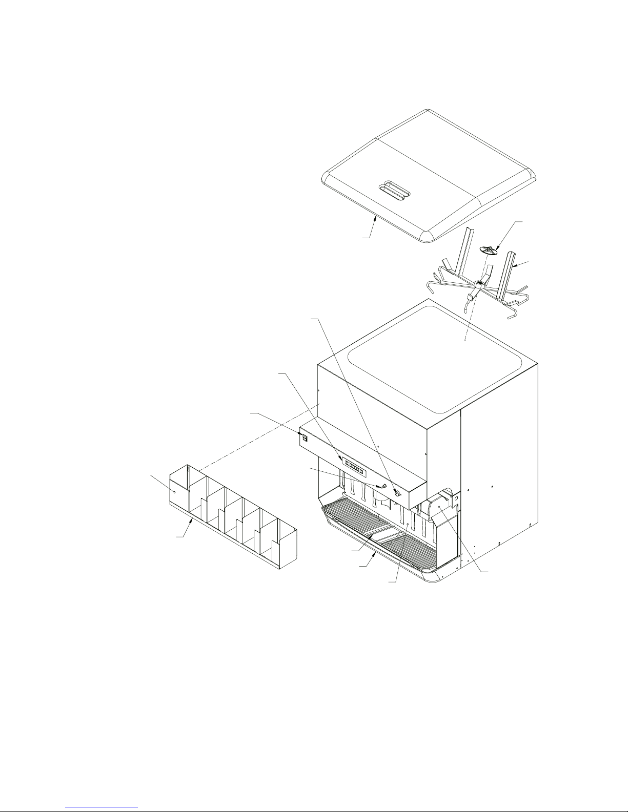
MANUAL ICE DISPENSE
RED PUSH BUTTON SWITCH
ICE PORTION
CONTROL MODULE
BEVERAGE FAUCET
ON/OFF SWITCH
RETAINER
ICE BIN COVER
ICE AGITATOR
REMOVABLE STRAW
HOLDER PANEL
LID/STRAW
HOLDER
MANUAL/AUTO ICE
TOGGLE SWITCH
CUP REST
DRIP TRAY
LOWER ACCESS
PANEL
FIGURE 1. PARTS IDENTIFICATION
BEVERAGE FAUCETS (8)
1
620919540
Page 4

THIS PAGE LEFT BLANK INTENTIONALLY
620919540
2
Page 5
START-UP AND OPERATING INSTRUCTIONS
Fill the hopper with ice and replace the lid. Allow 10 to 15 minutes for the cold plate to cool down. Repeat this
procedure whenever the dispenser has been standing overnight or other long periods without ice use. Start up the
beverage system and adjust faucets to the proper brix. Contact your local syrup distributor for complete
information on the beverage system.
To dispense ice, hold cup under ice chute and press the appropriate size button on the ice portion control located
above the ice chute. An extra ice portion may be obtained by pressing the increase key before pressing the
button.
For beverage dispensing, place a cup on the cup rest against the faucet lever of the desired flavor. Beverage will
be dispensed automatically filling the cup and shutting off. A delay feature is provided in the faucet controller to
“top-off” the drink after shut off.
CAUTION: Use caution to avoid spilling ice when filling dispenser. Clean up immediately
any spilled ice from filling or operating the unit. To prevent contamination of ice, the lid
must be installed at the unit at all times.
If the dispenser fails to dispense ice or beverage, see troubleshooting guide.
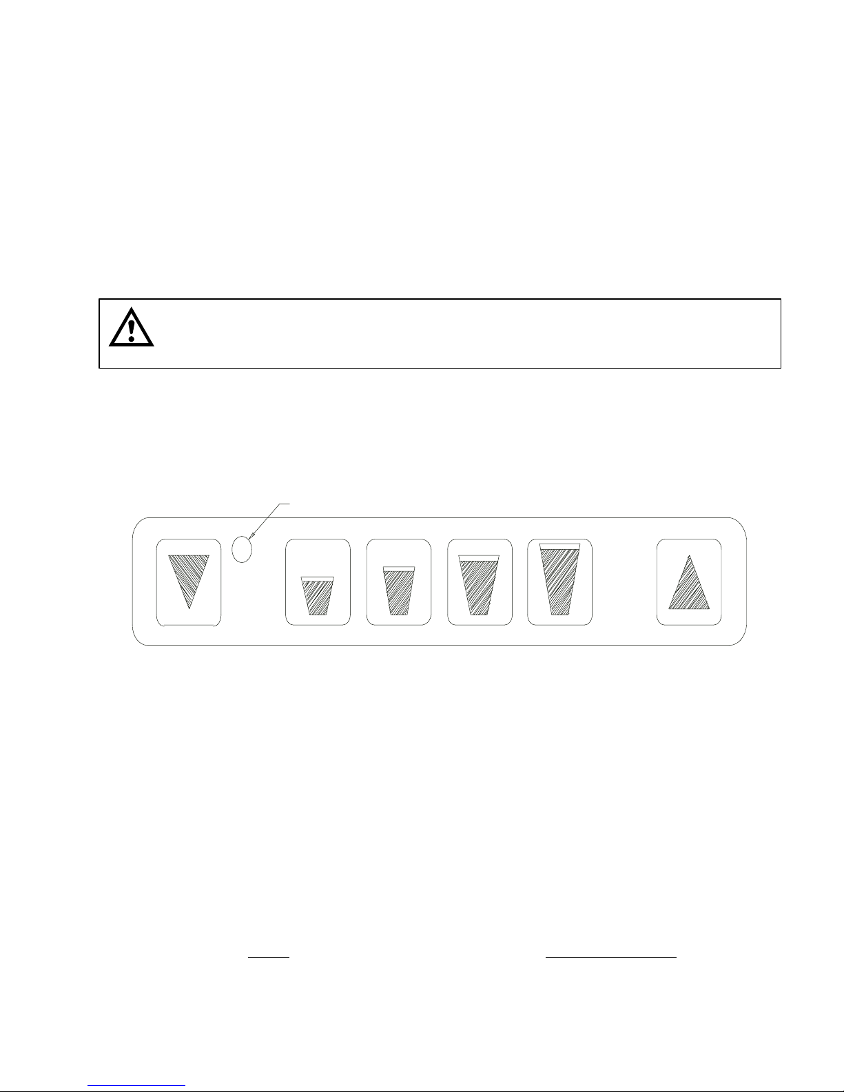
ICE PORTIONING SYSTEM OPERATION
INDICATOR LIGHT
DECREASE SMALL LARGEMEDIUM X-LARGE INCREASE
FIGURE 2. CUP SIZE LABEL
The ice portioning system consists of three main components:
1. Ice Portion Control
2. Ice Gate Mechanism
3. Solenoid Operated Air Valve
When a size button on the ice portion control is pressed, the control supplies a voltage to the air valve for a brief
period of time. The air cylinder attached to the ice gate will then open the ice gate for a short time allowing ice to
be dispensed from the ice chute.
The ice portion control has five modes to allow adjustment of the ice portions and for normal operation. They are
as follows: (Refer to Figure 2)
MODE
Normal operation Green
Cleaning mode Red/Amber flashing
Normal ice portion adjustment Amber
Extra ice portion adjustment Red
Agitation refill time adjustment Amber flashing
INDICATOR STATUS
3
620919540
Page 6

The control will return to Normal Operation Mode (green indicator) automatically if a button has not been operated
for a period of one minute whenever one of the three adjustment modes have been accessed.
NORMAL OPERATION
To dispense ice, hold a cup directly under the ice chute, then press the appropriate size button on the ice portion
control. To obtain a full cup of ice, press the increase button followed by the appropriate size button. The ice
portion control will not dispense ice and will display a flashing green indicator light if sufficient ice is not available
in the ice chute to dispense the selected size. The indicator light will return to solid green and ice dispensing will
resume after the ice chute has been filled.
The amount of ice dispensed for each size is changed in the Normal and Extra Ice Adjustment Modes. To access
the adjustment modes, press the decrease and increase button at the same time. The control will advance to the
next mode in the sequence as shown in the table on page 3 and the indicator light will change to identify which
mode is currently active.
CLEAN MODE
Access this mode to empty all the ice in the chute. To enter clean mode, press the decrease and increase buttons
at the same time. The indicator light will alternately display red and amber. To empty the ice chute, press any of
the size buttons. The ice gate will then open to allow the ice chute to empty. The ice gate will automatically close
after the ice has been emptied.
To return to normal operation, press the increase and decrease buttons at the same time; then press both buttons
three times in sequence. The indicator light will show amber, red, amber flashing, and finally green to indicate
normal operation.
NORMAL ICE PORTION ADJUSTMENT
From the Normal Operation Mode (green indicator), press both the decrease and increase buttons at the same
time twice. The amber indicator verifies that the normal portion adjustment mode has ben accessed.
To change the amount of ice dispensed, press and hold down the size button for the desired size to be changed.
While holding the size button, press the decrease or increase button to decrease/increase the ice portion size.
When the minimum ice portion adjustment has been reached, the indicator will flash at a slow rate; at the
maximum adjustment, the indicator will flash at a fast rate. After releasing the size button, the indicator light will
flash green for five seconds. During this time period a sample can be obtained to check the portion size by
pressing the size key. The indicator light will return to amber (normal portion adjustment mode) after the sample is
dispensed.
The indicator light will flash red after dispensing a sample, if an open circuit exists in the ice gate cylinder switch
wiring to the ice portion control or if an ice gate binding condition occurred during the sample. The indicator light
will display solid red briefly after a sample is dispensed if the ice gate cylinder switch was shorted.
To return to normal operation press the decrease and increase buttons at the same time, press twice.
EXTRA ICE PORTION ADJUSTMENT
The adjustment of Extra Ice Portion is accomplished in the same manner as ice portions, except the indicator light
displays red. To access this mode press both the decrease and increase buttons simultaneously three time from
the Normal Operation Mode (green indicator). The indicator will display red.
620919540
4
Page 7
AGITATION REFILL TIME ADJUSTMENT
To adjust the amount of ice chute refill agitation. begin by accessing the Extra Ice Portion Adjustment Mode (red
Indicator). Next, press and hold for the decrease and increase buttons for three seconds until the indicator flashes
amber. The indicator will flash up to four times, one flash corresponds to the minimum amount of refill agitation
and four flashes corresponds to the maximum amount of refill agitation. Change the amount of refill agitation by
pressing one of the four size buttons – the small button representing the minimum amount of refill agitation.
Increase the amount of refill agitation if the ice chute does not refill properly after dispensing ice.
To return to Normal Operation Mode, press the decrease and increase buttons at the same time.
MANUAL ICE DISPENSING OPERATION
A red pushbutton switch is provided on the upper front panel (see Figure 1) to manually dispense ice. This system
can be used for dispensing ice in portions other than cup-size or in the event of a malfunction with the ice portion
controller.
For manually dispensing ice, an auto/manual toggle switch is located adjacent to the ice portioning touch panel
(cup size selector) on the upper panel. The function of this switch is to bypass the gate solenoid valve (operated
by the portion controller) and to open the gate directly. Move the toggle switch to the “manual” position which
opens the gate immediately. Ice can now be dispensed by depressing and holding the red pushbutton switch for
the desired amount of ice. To return to the ice portioning mode of operation, move the toggle switch to the “auto”
position.
CAUTION: The gate closes immediately when the toggle switch is moved to the auto
position. Do not place fingers or foreign objects into the ice chute when operating the
toggle switch.
5
620919540
Page 8

THIS PAGE LEFT BLANK INTENTIONALLY
620919540
6
Page 9

MAINTENANCE
The following dispenser maintenance should be performed at the intervals indicated.
DAILY (or as required)
Remove foreign material from vending area drip tray to prevent drain blockage.
WEEKLY (or as required)
Clean vending area. Check for proper water drainage from the vending area drip tray.
MONTHLY
Clean and sanitize the hopper interior and beverage system if applicable (see CLEANING INSTRUCTIONS).
CLEANING INSTRUCTIONS
WARNING: Disconnect Power Before Cleaning! Do not use metal scrapers, sharp objects or
abrasives on the ice storage hopper, top cover, ice chute, and air cylinder access cover as
damage may result. Do not use solvents or other cleaning agents, as they may attack the
plastic material.
Soap solution - use a mixture of mild detergent and warm 100 degrees F potable water.
Sanitizing solution
solution to this ratio will create a solution of 200 PPM.
- use 1/2 ounce of household bleach in 1 gallon of potable water. Preparing the sanitizing
DISPENSER
1. CLEANING EXTERIOR SURFACES
Important: Perform the following daily.
A. Remove the cup rest from drip tray.
B. Wash the drip tray with soap solution. Rinse with clean water and allow solution to run down the drain.
C. Wash cup rest with soap solution and rinse in clean water. Install the cup rest into the drip tray.
D. Clean all exterior surfaces with soap solution and rinse in clean water.
2. CLEANING INTERIOR SURFACES
CAUTION: When pouring liquid into the hopper, do not exceed the rate of 1/2 gallon per
minute.
CAUTION: It will be necessary to have electrical power on to the unit in order to remove any
remaining ice from the storage hopper and ice chute. After the ice has been removed,
disconnect electrical power to the unit before proceeding with cleaning and sanitizing.
7
620919540
Page 10

A. Dispense all ice from the hopper and ice chute by switching the auto/manual toggle switch to the
“manual” position. The gate slide will then be held open to empty the ice chute. Depress the red
manual pushbutton switch to dispense all remaining ice from the hopper. Discard the ice. Return the
toggle switch to the “auto” position to close the gate slide.
B. IMPORTANT: Disconnect electrical power to the unit for the remainder of the cleaning and
sanitizing procedure.
C. Cold plate inspection before cleaning.
1. Remove splash panel.
2. Remove the plastic cold plate access cover to expose the cold plate.
3. Remove any remaining ice from the cold plate surface and discard.
4. Locate and remove any debris from the cold plate, drain trough and make certain that the drain
holes are not clogged.
5. Reinstall the cold platecover.
6. Reinstall the splash panel.
D. Remove the plastic lid, agitator retainer (turn counterclockwise to unscrew), and agitator from the ice
storage hopper.
E. Using a long handle nylon bristle brush, clean the interior of the hopper and cold plate with the soap
solution. The cold plate can be reached by going through the ice opening on the hopper bottom. Make
certain to reach the entire surface of the cold plate in cluding the corners. Thoroughly rinse the hopper
interior and cold plate with clean potable water.
F. Clean the agitator, agitator retainer, and lid with the soap solution. Thoroughly rinse with clean potable
water. Reassemble the agitator and retainer in the hopper. Make sure that the retainer is secured
tightly (turn clockwise to screw in place).
G. Clean and sanitize the ice chute as described below:
1. Remove the ice chute cover (snap-fit) by spreading the sides apart slightly to disengage the tabs in
the cover from the ice chute and sliding down to remove the cover. The ice chute (rear half) and
the ice gate are now exposed for cleaning.
2. Remove the black plastic access cover for the air cylinder from the splash panel (2 thumbscrews).
3. Wash the ice chute cover, ice chute (rear half), ice gate, and air cylinder access cover with the
soap solution. Thoroughly rinse with clean potable water.
4. Using a mechanical spray bottle filled with sanitizing solution, spray these parts with sanitizer.
Allow to air dry.
5. Reassemble the ice chute cover and air cylinder access cover.
H. Using the mechanical spray bottle filled with sanitizing solution, spray the entire hopper interior, agitator
assembly, and hopper lid. Allow to air dry. Replace the lid on the unit.
620919540
8
Page 11

BEVERAGE SYSTEM
CLEANING
Soap solution - Use a mixture of mild detergent and warm 100 degrees F potable water.
Sanitizing solution
solution to this ratio will provide the required solution of 200 PPM.
Cleaning tank
potable water.
- Use 1/2 ounce of household bleach in 1 gallon of potable water. Preparing the sanitizing
- Fill clean, empty tank with a mixture of mild detergent and five (5) gallons of warm 120 degrees F
CLEANING DISPENSING VALVES
Refer to addendum supplied with the unit that is applicable to the manufacturer of the valves installed on the unit.
SANITIZING
IMPORTANT: Only trained and qualified persons should perform these cleaning and sanitizing
procedures.
Sanitize tank systems, Post-Mix and Pre-Mix
1. Remove all the quick disconnects from all the tanks. Fill a suitable pail or bucket with soap solution.
2. Submerge all disconnects (gas and liquid) in the soap solution and then clean them using a nylon bristle
brush. (Do not use a wire brush). Rinse with clean water.
3. Prepare sanitizing solution and using a mechanical spray bottle, spray the disconnects. Allow to air dry.
4. Using a clean, empty tank, prepare five (5) gallons of the sanitizing solution. Rinse the tank disconnects with
approximately 9 oz. of the
5. Prepare cleaning tank by filling clean five (5) gallon tank with a mixture of mild detergent and 120 degrees F
potable water.
6. Connect a gas disconnect to the tank and then apply one of the product tubes to the cleaning tank. Operate
the appropriate valve until liquid dispensed is free of any syrup.
7. Disconnect cleaning tank and hook up sanitizing tank to syrup line and CO
8. Energize beverage faucet until chlorine sanitizing solution is dispensed through the faucet. Flush at least two
(2) cups of liquid to insure that the sanitizing solution has filled the entire length of the syrup tubing.
9. Allow sanitizer to remain in lines for fifteen (15) minutes.
10. Repeat the step above, applying a different product tube each time until all tubes are filled with the sanitizing
solution.
11. For post-mix valves, remove the nozzle and syrup diffuser and clean them in a mild soap solution. Rinse
with clean water, then reinstall the nozzle and syrup diffuser on the valve.
12. For pre-mix valves, disconnect all product tubes from the tank of sanitizing solution and then open the valves
to allow the pressure to be relieved. Remove the valves from the dispenser, disassemble and wash
thoroughly in a mild soap solution.
sanitizing solution. Close the tank.
system.
2
9
620919540
Page 12

13. Rinse the parts in clean water, reassemble the valve and reconnect it to the dispenser.
14. Discard the tank of sanitizing solution and reconnect the product (syrup or pre-mix) tanks. Operate the
valves until all sanitizer has been flushed from the system and only product (syrup or pre-mix) is flowing.
Sanitize syrup lines, B-I-B Systems
1. Remove all the quick disconnects from all the B-I-B containers.
2. Fill a suitable pail or bucket with soap solution.
3. Submerge all disconnects (gas and liquid) in the soap solution and then clean them using a nylon bristle
brush. (Do not use a wire brush). Rinse with clean water.
4. Using a plastic pail, prepare approximately five (5) gallons of sanitizing solution.
5. Rinse the B-I-B disconnects in the sanitizing solution.
6. Sanitizing fittings must be attached to each B-I-B disconnect. If these fittings are not available, the fittings
from empty B-I-B bags can be cut from the bags and used. These fittings open the disconnect so the
sanitizing solution can be drawn through the disconnect.
7. Place all the B-I-B disconnects into the pail of sanitizing solution. Operate all the valves until the sanitizing
solution is flowing from the valve. Allow sanitizer to remain in lines for fifteen (15) minutes.
8. Remove the nozzle and syrup diffuser from each valve and clean them in a soap solution. Rinse with clean
water and reassemble the nozzle and syrup diffuser to the valve.
9. Remove the sanitizing fittings from the B-I-B disconnects and connect the disconnects to the appropriate
B-I-B container. Operate the valves until all sanitizer has been flushed from the system and syrup is flowing
freely.
620919540
10
Page 13

TROUBLESHOOTING
IMPORTANT: Only qualified personnel should service internal components or electrical wiring.
WARNING: If repairs are to be made to the beverage system, remove quick disconnects
from the applicable product tank, then relieve the system pressure before proceeding. If
repairs are to be made to the CO
system, stop dispensing, shut off the CO
2
relieve the system pressure before proceeding. If repairs are to be made to the ice dispensing
system, make sure electrical power is disconnected from the unit.
Trouble Probable Cause Remedy
NOTE: should your unit fail to operate properly, check that there is power to the unit and that the
hopper contains ice. If the unit does not dispense, check the following chart under the
appropriate symptoms(s) to aid in locating the defect.
supply, then
2
BLOWN FUSE OR CIRCUIT
BREAKER.
SLUSHY ICE. WATER IN
HOPPER
BEVERAGES DO NOT
DISPENSE.
BEVERAGES TOO SWEET.
A. Short circuit in wiring (115V
A. Replace defective wiring.
circuit).
B. Defective agitator motor. B. Replace agitator motor.
A. Blocked drain. A. Open–up/flush out drain.
B. Unit not level. B. Level unit.
C. Poor ice quality due to water
quality or ice maker problems.
C. Install water filter system. For
Icemaker problems, consult
icemaker manual.
D. Improper use of flaked ice. D. Replaced flaked ice with “cube
style ice (see page 2, Unit
Description).
A. No 24 volt power to faucets. A. Check that beverage switch is
“on”. Check 24V transformers.
B. No CO2 pressure. B. Check CO
regulator. Check CO
2
tank pressure.
A. Carbonator not working. A. Check carbonator.
B. No CO2 pressure in
carbonator.
B. Check CO2 regulator. Check CO
tank pressure.
C. Faucet brix requires adjusting. C. Brix Faucet.
2
2
BEVERAGES NOT SWEET
ENOUGH.
BEVERAGES NOT COLD
(UNITS WITH BUILD-IN COLD
PLATE).
NOTE: Contact your local syrup or beverage equipment distributor for additional information and
trouble shooting of beverage system.
A. Empty syrup tank. A. Refill syrup tank.
B. Faucet Brix requires adjusting. B. Brix Faucet.
A. Unit standing with no ice in
A. Refill hopper with ice.
hopper - no ice in cold plate
cabinet.
11
620919540
Page 14

Trouble RemedyProbable Cause
NO ICE DISPENSED FROM
ICE PORTION CONTROLLER
A. Insufficient ice supply in ice
A. Replenish ice supply as required.
bin.
B. Ice in ice bin bridged (stuck
B. Gently tap on ice to break it loose.
together).
C. No electrical power to
dispenser.
D. Insufficient or no CO
supply
2
C. Plug in dispenser power cord, or
check fuse or circuit breaker.
D. Restore CO2 supply to dispenser.
to dispenser.
E. Ice chute cover not properly
installed.
F. Defective ice chute interlock
E. Make sure that cover is “snapped”
into place.
F. Replace interlock switch.
switch.
G. Defective interlock relay. G. Replace relay.
H. Defective 24V transformer. H. Replace transformer.
I. Defective portion controller.
J. Defective ice gate cylinder.
K. Defective ice gate solenoid
I. Replace controller.
J. Replace cylinder.
K. Replace solenoid valve.
valve.
NO ICE DISPENSED FROM
MANUAL ICE DISPENSE
PUSHBUTTON SWITCH
L. Agitation relay wiring incorrect.
M. Defective agitation relay.
N. Defective agitator motor start
capacitor or start relay.
A. Manual/Auto toggle switch in
“Auto” position.
B. Insufficient or no CO2 supply
to dispenser.
C. Defective 24VAC transformer.
D. Defective manual override
solenoid valve.
E. Defective manual ice dispense
pushbutton switch.
F. Defective agitator motor or
start capacitor or start relay.
L. Red wire should be connected to
“+” terminal (#3) of relay coil.
M. Replace relay.
N. Replace defective component.
A. Move toggle switch to “Manual”
position.
B. Restore CO2 supply to dispenser.
C. Replace Transformer
D. Replace valve.
E. Replace switch.
F. Replace defective component.
G. Defective ice gate cylinder. G. Replace cylinder
620919540
12
Page 15

Trouble RemedyProbable Cause
ICE DISPENSING DURING
AUTOMATIC AGITATION
A. Manual/Auto toggle switch in
“manual” position.
B. Defective ice gate cylinder.
C. Defective ice gate solenoid
valve.
D. Defective portion controller.
A. Move toggle switch to “auto”
position.
B. Replace cylinder.
C. Replace valve.
D. Replace controller.
13
620919540
Page 16

THIS PAGE LEFT BLANK INTENTIONALLY
620919540
14
Page 17

PARTS LIST
90
56
94
40
77
92
79
43
46
50
67
49
62
1
53
26
11
3
40
72
15
40
37
70
9
51
72
42
45
2
52
77
57
75
61
59
88
76
71
88
148688
25
44
48
16
22
60
76
21
81
36
77
74
32
66
41
5
72
88
72
54
20
29
88
7
82
83
4
78
38
72
95
34
17
23
88
30
84
74
24
10
88
34
20
28
86
8
13
31
68
100
72
88
55
69
63
19
101
64
64
47
18
12
72
58
65
6
63
93
88
72
102
73
80
39
33
87
27
FIGURE 3. CABINET SECTION EXPLODED VIEW
15
620919540
Page 18

Item
No. Part No. Name
1 620031818 Ice Gate
2 620706001 Air Cylinder
3 620701208 Hex Nut, 5/8-18, S.S.
4 29541R Plate, Motor Mounting
5 29694 Agitator Ass’y
6 29555 Cover, Rear Wrapper
7 629086701 Splash Panel Ass’y (Insulated)
8 620028702 Extension Ass’y, Drip T ray
9 28708 Lid and Straw Holder
10 29547 Wrapper
11 31934 On/Off Switch (Beverage Faucets)
12 620407447 Panel/Cold Plate/Faucet Ass’y
13 53011 Elbow, Cold Plate Drain
14 31960 Toggle Switch, Auto/Manual
15 32839 Portion Control, Ice
16 50767 Bushing
17 10145 Pin, Drip Tray Mounting
18 15090 Baffle
19 620041018 Baffle
20 52084 Splash Guard
21 30794 Agitator Motor Heater 120 Volt
22 30894 Switch, Red, Pushbutton
23 620031807 Upper Support, Electrical Box
24 620031812 Mounting Bracket, E l e c t r i c a l B o x
25 33387 Agitator Motor 120 Volt
26 620031814 Box Control, Portion Ext.
27 53268 Insulated Cold Plate Cover
28 620041016 Bracket, Ice Chute Stabilizer
29 620031804 Cover, Electrical Box
30 620307702 Electrical Box Ass’y
31 620041017 Stabilizer Wire, Ice Chute
32 29542 Bracket, Motor Mounting
33 53255 Cover, Access (Cold Plate)
34 71010 Washer, Captivating No. 8
35 620041020 Mounting Bracket, Portion Controller
36 620308301 Connector , Power Inlet
37 620505903 Gate Gasket
38 620046001 Cover Access, Air Cylinder, Black
39 620019701 Hinge Gusset
40 620702505 Bushing, Air Cylinder
41 70188 Thumbscrew, No. 8-32
42 70122 Screw, No. 4 By 3/8-In. Long
43 620705901 Screw, No. 4 Type B By 3/8-In. Long
44 53199 Shaft Seal, Agitator Motor
45 32953 Ice Chute Interlock Switch
46 31981 Actuator Interlock Switch
47 51908 Hole Plug
48 71025 Strap, 3/8-16 Threaded (Agitator Motor
49 620505901 Ice Chute
50 620505902 Cover, Ice Chute
51 70075 Nut, 6-32, Keps
52 15132 Bracket, Agitator Motor Strap
53 620701202 Hex Nut, 1/4-28
54 53211 Drip Tray , Insulated, Gray
55 53018 Lid, Dispenser, Gray
56 620506008 Hopper Ass’y, Insulated
57 620506006 Fitting, 90 Elbow, 1/8NPT By 1/4 Tube
Mounting)
620919540
16
Page 19

Item
No. Part No. Name
58 52967 Plug, Plastic (.312 Hole)
59 620028283 Retainer , Corner Cushion
60 620041402 Merchandiser, Stainless Steel
61 620506018 Cushion, Corner
62 70016 Hex Nut, No. 10-32, S.S.
63 50459 Bushing, 1.00 Dia.
64 50475 Bushing, .875 Dia.
65 70242 Screw, No. 10-32 By 3/8-In. Long
66 70015 Hex Nut, No. 10-32, Keps
67 70056 Flatwasher, .219 I.D. x .500 O.D.
68 50335 Armaflex Tubing, 1 3/8 O.D. By
69 50822 Nylon Mounting Tie
70 620513506 Drip Shield Cylinder
71 50130 Armaflex Tubing, 5/8 I.D. By 3/8 Wall
72 70171 Screw, No. 8-32 By 3/8-In. Long
73 70178 Screw, No. 8-32 By 1/2-In. Long
74 70204 Sheet Metal Screw, No. 8 By 1/2-In.
75 50705 Nylon Mounting Tie
76 71033 Screw, Hex Hd, 3/8-16 By 3/4-In. Long
77 70068 Washer, 3/8 I.D.
*78 91997 Label, Plumbing Manifold, RT to LT
79 71061 Washer, .480 I.D. x 1.1 O.D. x
80 70320 Pop Rivet, 1/8 Dia. (.063-.125-In. Grip
81 70341 Spring, Agitator Motor Heater
82 71006 Screw, No. 8-32 By 2 1/8-In. Long
83 70478R Clip, Push-on
84 70555 Screw, No. 8-32 By 2 5/16-In. Long
*85 70798 Tool, Beverage Valve, LEV or FFV
86 620701601 Sheet Metal Screw, No. 10 By 1/2-In.
87 70456 Pop Rivet, 3/16 Dia.
88 70959 Hex Nutsert, No. 8-32
89 620516201 Air Cylinder Splash Shield (Not Shown)
90 15087 Retainer, Agitator
91 620516202 Back Air Cylinder Splash Shield (Not
92 71059 Wing Nut, 3/8-16
93 92334 Label Inlet, 8-FL., LT to R T
92345 Label Inlet, 8-FL., RT to L T
94 71028 Shoulder Screw, 1/4-20
95 71094 Cup Rest
*96 51288 Adapter, 1-In. Barb By 3/4 MPT (For
*97 50952 Adapter, 3/4 Soc By 3/4 FPT (For Drip
*98 70750 Hose Clamp (For Drip Tray Drain)
*99 620702201 Brush, Cold Plate Cleaning
100 92050 Decal, Cabinet, L.S.
101 92051 Decal, Cabinet, Back
102 92050 Decal, Cabinet, R.S.
x .049 Thk.
3/8-Wall
Long
3+1+1+3
.063 Thk
Range)
Long
Shown)
Drip Tray Drain)
Tray Drain)
NOTES: *NOT SHOWN
17
620919540
Page 20

21
25
10
16
26
18
11
14
13
21
10
15
17
20
21
4
7
8
27
5
25
24
21
12
9
19
22
FIGURE 4. ELECTRICAL BOX ASSEMBLY
Item
No. Part No. Name
1 620031802 Electrical Box
2 32714 Diode Ass’y, T ransient Voltage
3 449999999 Transformer, 24 V olt
4 31107 Terminal Board
5 33162 Start Relay, Agitator Motor
6 620307501 Agitation Relay
7 620031810 Strap Capacitor
8 33160R Start Capacitor, Agitator Motor
9 620701206 Mounting Nut, Filter/Regulator
10 620031811 Mounting Bracket, Solenoid Valve
11 620701204 Air Filter/Regulator Ass’y
12 620702504 Tee, 1/8-MPT x 1/8-FPT x 1/8-FPT
13 620702501 Tee, 1/8-FPT x 1/8-FPT x 1/8-FPT
14 620702503 Gage Pressure
15 620404301 Nipple, 1/8-NPT By 1 1/2-In. Long
16 620404303 Manual Override Solenoid Valve
17 620702102 Pneumatic Gate Solenoid Valve
18 620701207 Nipple, Close 1/8-NPT Hex
19 70663 Fitting, 1/4-Barb x 1/8-MPT
20 620506006 Elbow, 1/8-MPT x 1/4-Tube
21 620512101 Tube, .250 O.D. x .0425 Wall
22 50299 Tubing, Non-Coke, .265 I.D.
*23 30995 Power Cord Ass’y
24 70661 Fitting, 1/8-FPT x 1/4-MPT
25 620404302 Elbow, 1/4-MPT x 1/4-Tube
26 620702506 Nipple/Orifice (.052) 1/8-NPT
27 31206 Interlock Relay
3
6
3
1
NOTES: *NOT SHOWN
620919540
18
Page 21

WARRANTY
IMI Cornelius Inc. warrants that all equipment and parts are free from defects in material and workmanship
under normal use and service. For a copy of the warranty applicable to your Cornelius, Remcor or Wilshire
product, in your country, please write, fax or telephone the IMI Cornelius office nearest you. Please provide the
equipment model number, serial number and the date of purchase.
IMI Cornelius Offices
AUSTRALIA D P.O. 210, D RIVERWOOD, D NSW 2210, AUSTRALIA D (61) 2 533 3122 D FAX (61) 2 534 2166
D AM LANGEN FELDE 32 D A-1222 D VIENNA, AUSTRIA D (43) 1 233 520 D FAX (43) 1-2335-2930
AUSTRIA
D BOSKAPELLEI 122 D B-2930 BRAASCHAAT, BELGIUM D (32) 3 664 0552 D FAX (32) 3 665 2307
BELGIUM
D RUA ITAOCARA 97 D TOMAS COELHO D RIO DE JANEIRO, BRAZIL D (55) 21 591 7150 D FAX (55) 21 593 1829
BRAZIL
ENGLAND
D TYTHING ROAD ALCESTER D WARWICKSHIRE, B49 6 EU, ENGLAND D (44) 789 763 101 D FAX (44) 789 763 644
D 71 ROUTE DE ST. DENIS D F-95170 DEUIL LA BARRE D PARIS, FRANCE D (33) 1 34 28 6200 D FAX (33) 1 34 28 6201
FRANCE
GERMANY
GREECE
HONG
ITALY
NEW
SINGAPORE
SPAIN
USA
D CARL LEVERKUS STRASSE 15 D D-4018 LANGENFELD, GERMANY D (49) 2173 7930 D FAX (49) 2173 77 438
D 488 MESSOGION AVENUE D AGIA PARASKEVI D 153 42 D ATHENS, GREECE D (30) 1 600 1073 D FAX (30) 1 601 2491
KONG D 1104 TAIKOTSUI CENTRE D 11-15 KOK CHEUNG ST D TAIKOKTSUE, HONG KONG D (852) 789 9882 D FAX (852) 391 6222
D VIA PELLIZZARI 11 D 1-20059 D VIMARCATE, ITALY D (39) 39 608 0817 D FAX (39) 39 608 0814
ZEALAND D 20 LANSFORD CRES. D P.O. BOX 19-044 AVONDALE D AUCKLAND 7, NEW ZEALAND D (64) 9 8200 357 D FAX (64) 9 8200 361
D 16 TUAS STREET D SINGAPORE 2263 D (65) 862 5542 D FAX (65) 862 5604
D POLIGONO INDUSTRAIL D RIERA DEL FONOLLAR D E-08830 SANT BOI DE LLOBREGAT D BARCELONA, SPAIN D (34) 3 640 2839 D FAX (34) 3 654 3379
D ONE CORNELIUS PLACE D ANOKA, MI NNESOTA D (612) 421-6120 D FAX (612) 422-3255
LD004
4/21/98
62091954019
Page 22

IMI CORNELIUS INC.
Corporate Headquarters:
Anoka, Minnesota 55303-6234
One Cornelius Place
(763) 421-6120
(800) 238-3600
 Loading...