


 Loading...
Control Getting Started
Guide
Unidrive M700
Unidrive M701
Unidrive HS70
Unidrive HS71
Universal Variable Speed AC drive for induction and permanent magnet motors
Part Number: 0478-0239-02
Issue: 2

|
Contents |
|
1 |
Safety information ....................................................................................... |
3 |
2 |
Introduction .................................................................................................. |
6 |
2.1 |
Operating modes ...................................................................................................... |
6 |
3 |
Control connections .................................................................................... |
8 |
3.1 |
Position feedback connections ................................................................................. |
8 |
3.2 |
Communications connections ................................................................................ |
10 |
3.3 |
Shield connections ................................................................................................. |
11 |
3.4 |
Control connections ............................................................................................... |
12 |
4 |
Getting started ........................................................................................... |
13 |
4.1Quick start commissioning / start-up using Unidrive M Connect
4.2 |
(V02.00.00.00 onwards) ......................................................................................... |
13 |
4.3 |
Keypad / display ..................................................................................................... |
16 |
4.4 |
Keypad operation ................................................................................................... |
17 |
4.5 |
Menu 0 ................................................................................................................... |
18 |
4.6 |
Menu structure ....................................................................................................... |
18 |
4.7 |
Advanced menus ................................................................................................... |
19 |
4.8 |
Changing the operating mode ................................................................................ |
20 |
4.9 |
Saving parameters ................................................................................................. |
21 |
4.10 |
Restoring parameter defaults ................................................................................. |
21 |
4.11 |
Displaying parameters with non-default values only .............................................. |
21 |
4.12 |
Displaying destination parameters only ................................................................. |
21 |
4.13 |
Parameter access level and security ..................................................................... |
22 |
4.14 |
NV Media Card operation ....................................................................................... |
22 |
4.15 |
Transferring data .................................................................................................... |
25 |
5 |
Basic parameters (Menu 0) ....................................................................... |
26 |
5.1 |
Parameter descriptions .......................................................................................... |
29 |
6 |
Running the motor ..................................................................................... |
34 |
6.1 |
Quick start Connections ......................................................................................... |
34 |
6.2 |
Quick Start / start-up ............................................................................................. |
36 |
7 |
Further information ................................................................................... |
46 |
7.1 |
Diagnostics ............................................................................................................. |
46 |
Unidrive M700/M701 / Unidrive HS70/HS71 Control Getting Started Guide Issue Number: 2

1 Safety information
1.1Warnings, Cautions and Notes
A Warning contains information which is essential for avoiding a safety hazard.
WARNING
A Caution contains information which is necessary for avoiding a risk of damage to the product or other equipment.
CAUTION
NOTE A Note contains information, which helps to ensure correct operation of the product.
1.2Electrical safety - general warning
The voltages used in the drive can cause severe electrical shock and/or burns, and could be lethal. Extreme care is necessary at all times when working with or adjacent to the drive. Specific warnings are given at the relevant places in this guide.
1.3System design and safety of personnel
The drive is intended as a component for professional incorporation into complete equipment or a system. If installed incorrectly, the drive may present a safety hazard.
The drive uses high voltages and currents, carries a high level of stored electrical energy, and is used to control equipment which can cause injury.
Close attention is required to the electrical installation and the system design to avoid hazards either in normal operation or in the event of equipment malfunction. System design, installation, commissioning/start-up and maintenance must be carried out by personnel who have the necessary training and experience. They must read this safety information and this User Guide carefully.
The STOP and SAFE TORQUE OFF functions of the drive do not isolate dangerous voltages from the output of the drive or from any external option unit. The supply must be disconnected by an approved electrical isolation device before gaining access to the electrical connections.
With the sole exception of the SAFE TORQUE OFF function, none of the drive functions must be used to ensure safety of personnel, i.e. they must not be used for safety-related functions.
Careful consideration must be given to the functions of the drive which might result in a hazard, either through their intended behavior or through incorrect operation due to a fault. In any application where a malfunction of the drive or its control system could lead to or allow damage, loss or injury, a risk analysis must be carried out, and where necessary, further measures taken to reduce the risk - for example, an over-speed protection device in case of failure of the speed control, or a fail-safe mechanical brake in case of loss of motor braking.
The SAFE TORQUE OFF function may be used in a safety-related application. The system designer is responsible for ensuring that the complete system is safe and designed correctly according to the relevant safety standards.
1.4Environmental limits
Instructions in this guide regarding transport, storage, installation and use of the drive must be complied with, including the specified environmental limits. Drives must not be subjected to excessive physical force.
Unidrive M700/M701 / Unidrive HS70/HS71 Control Getting Started Guide |
3 |
Issue Number: 2 |
|
<![endif]>information Further motor the Running parameters Basic started Getting connections Control Introduction information Safety 0) (Menu

1.5Access
Drive access must be restricted to authorized personnel only. Safety regulations which apply at the place of use must be complied with.
1.6Fire protection
The drive enclosure is not classified as a fire enclosure. A separate fire enclosure must be provided. For further information, refer to the Drive User Guide.
1.7Compliance with regulations
The installer is responsible for complying with all relevant regulations, such as national wiring regulations, accident prevention regulations and electromagnetic compatibility (EMC) regulations. Particular attention must be given to the cross-sectional areas of conductors, the selection of fuses or other protection, and protective ground (earth) connections.
This guide contains instruction for achieving compliance with specific EMC standards.
Within the European Union, all machinery in which this product is used must comply with the following directives:
2006/42/EC: Safety of machinery. 2004/108/EC: Electromagnetic Compatibility.
1.8Motor
Ensure the motor is installed in accordance with the manufacturer’s recommendations. Ensure the motor shaft is not exposed.
Standard squirrel cage induction motors are designed for single speed operation. If it is intended to use the capability of the drive to run a motor at speeds above its designed maximum, it is strongly recommended that the manufacturer is consulted first.
Low speeds may cause the motor to overheat because the cooling fan becomes less effective. The motor should be installed with a protection thermistor. If necessary, an electric forced vent fan should be used.
The values of the motor parameters set in the drive affect the protection of the motor. The default values in the drive should not be relied upon.
It is essential that the correct value is entered in Pr 00.046 motor rated current. This affects the thermal protection of the motor.
1.9Mechanical brake control
The brake control functions are provided to allow well co-ordinated operation of an external brake with the drive. While both hardware and software are designed to high standards of quality and robustness, they are not intended for use as safety functions, i.e. where a fault or failure would result in a risk of injury. In any application where the incorrect operation of the brake release mechanism could result in injury, independent protection devices of proven integrity must also be incorporated.
1.10Adjusting parameters
Some parameters have a profound effect on the operation of the drive. They must not be altered without careful consideration of the impact on the controlled system. Measures must be taken to prevent unwanted changes due to error or tampering.
4 |
Unidrive M700/M701 / Unidrive HS70/HS71 Control Getting Started Guide |
|
Issue Number: 2 |

1.11Electrical installation
1.11.1Electric shock risk
The voltages present in the following locations can cause severe electric shock and may be lethal:
•AC supply cables and connections
•Output cables and connections
•Many internal parts of the drive, and external option units
Unless otherwise indicated, control terminals are single insulated and must not be touched.
1.11.2Stored charge
The drive contains capacitors that remain charged to a potentially lethal voltage after the AC supply has been disconnected. If the drive has been energized, the AC supply must be isolated at least ten minutes before work may continue.
<![endif]>information Further motor the Running parameters Basic started Getting connections Control Introduction information Safety 0) (Menu
Unidrive M700/M701 / Unidrive HS70/HS71 Control Getting Started Guide |
5 |
Issue Number: 2 |
|

2 Introduction
This guide covers the Unidrive M700/HS70 and Unidrive M701/HS71 products.
Unidrive M700/HS70 / Unidrive M701/HS71 features
•Analog and digital I/O with single channel SAFE TORQUE OFF input
•NV Media Card for parameter copying and data storage
•Universal high performance drive for induction, servo, permanent magnet and linear motors
•Flexibility with speed and position measurement, supporting multiple devices and all common interfaces
•Ethernet fieldbus communication (Unidrive M700/HS70)
•Provides an equivalent for Unidrive SP (Unidrive M701/HS71)
•485 serial communication interface (Unidrive M701/HS71)
2.1Operating modes
The drive is designed to operate in any of the following modes:
1. Open loop mode
Open loop vector mode Fixed V/F mode (V/Hz) Quadratic V/F mode (V/Hz)
2. RFC - A
With position feedback sensor
Without position feedback sensor (Sensorless) 3. RFC - S
With position feedback sensor
Without position feedback sensor (Sensorless)
2.1.1Open loop mode
The drive applies power to the motor at frequencies varied by the user. The motor speed is a result of the output frequency of the drive and slip due to the mechanical load. The drive can improve the speed control of the motor by applying slip compensation. The performance at low speed depends on whether V/F mode or open loop vector mode is selected.
Open loop vector mode
The voltage applied to the motor is directly proportional to the frequency except at low speed where the drive uses motor parameters to apply the correct voltage to keep the flux constant under varying load conditions.
Typically 100 % torque is available down to 1 Hz for a 50 Hz motor.
Fixed V/F mode
The voltage applied to the motor is directly proportional to the frequency except at low speed where a voltage boost is provided which is set by the user. This mode can be used for multi-motor applications.
Typically 100 % torque is available down to 4 Hz for a 50 Hz motor.
Quadratic V/F mode
The voltage applied to the motor is directly proportional to the square of the frequency except at low speed where a voltage boost is provided which is set by the user. This mode can be used for running fan or pump applications with quadratic load characteristics or for multi-motor applications. This mode is not suitable for applications requiring a high starting torque.
6 |
Unidrive M700/M701 / Unidrive HS70/HS71 Control Getting Started Guide |
|
Issue Number: 2 |

2.1.2RFC-A mode
Rotor Flux Control for Asynchronous (induction) motors (RFC-A) encompasses closed loop vector control with a position feedback device
With position feedback
For use with induction motors with a feedback device installed. The drive directly controls the speed of the motor using the feedback device to ensure the rotor speed exactly as demanded. Motor flux is accurately controlled at all times to provide full torque all the way down to zero speed.
Without position feedback (Sensorless)
Sensorless mode provides closed loop control without the need for position feedback by using current, voltages and key motor parameters to estimate the motor speed. It can eliminate instability traditionally associated with open loop control such as operating large motors with light loads at low frequencies.
2.1.3RFC- S
Rotor Flux Control for Synchronous (permanent magnet brushless) motors (RFC-S) provides closed loop control with position feedback device.
With position feedback
For use with permanent magnet brushless motors with a feedback device installed.
The drive directly controls the speed of the motor using the feedback device to ensure the rotor speed is exactly as demanded. Flux control is not required because the motor is self excited by the permanent magnets which form part of the rotor.
Absolute position information is required from the feedback device to ensure the output voltage is accurately matched to the back EMF of the motor. Full torque is available all the way down to zero speed.
Without position feedback
For use with permanent magnet brushless motors without a feedback device installed.
Flux control is not required because the motor is self excited by the permanent magnets which form part of the rotor.
Full torque is available all the way down to zero speed, with salient motors.
<![endif]>information Further motor the Running parameters Basic started Getting connections Control Introduction Introduction 0) (Menu
Unidrive M700/M701 / Unidrive HS70/HS71 Control Getting Started Guide |
7 |
Issue Number: 2 |
|

3 Control connections
3.1Position feedback connections
The following functions are provided via the 15-way high density D-type connector on the drive:
•Two position feedback interfaces (P1 and P2).
•One encoder simulation output.
•Two freeze trigger inputs (marker inputs).
•One thermistor input.
The P1 position interface is always available but the availability of the P2 position interface and the encoder simulation output depends on the position feedback device used on the P1 position interface.
NOTE Refer to the Drive User Guide for information regarding the supported feedback devices on the P1 and P2 position interface and the encoder stimulation output.
Figure 3-1 Location of position feedback connection
Front view |
End view |
|
5 |
1 |
10 |
6 |
15 |
11 |
Drive encoder connector |
|
Female 15-way D-type |
|
8 |
Unidrive M700/M701 / Unidrive HS70/HS71 Control Getting Started Guide |
|
Issue Number: 2 |

3.1.1Position feedback connection details
Table 3-1 |
P1 position feedback connection details |
|
|
|
|
|
|
|
|
|
||||||
|
|
|
|
|
|
|
|
|
|
|
|
|
|
|
|
|
P1 Position |
|
|
|
|
|
|
Connections |
|
|
|
|
|
|
|
||
feedback |
|
|
|
|
|
|
|
|
|
|
|
|
|
|
|
|
interface |
1 |
2 |
3 |
4 |
5 |
6 |
7 |
8 |
|
9 |
10 |
11 |
12 |
13 |
14 |
15 |
Pr 03.038 |
|
|||||||||||||||
|
|
|
|
|
|
|
|
|
|
|
|
|
|
|
|
|
|
|
|
|
|
|
|
|
|
|
|
|
|
|
|
|
|
AB (0) |
A |
A\ |
B |
B\ |
Z |
Z\ |
|
|
|
|
|
|
|
|
|
|
|
|
|
|
|
|
|
|
|
|
|
|
|
|
|
|
|
FD (1) |
F |
F\ |
D |
D\ |
Z |
Z\ |
|
|
|
|
|
|
|
|
|
|
|
|
|
|
|
|
|
|
|
|
|
|
|
|
|
|
|
FR (2) |
F |
F\ |
R |
R\ |
Z |
Z\ |
|
|
|
|
|
|
|
|
|
|
|
|
|
|
|
|
|
|
|
|
|
|
|
|
|
|
|
AB Servo (3) |
A |
A\ |
B |
B\ |
Z |
Z\ |
U |
U\ |
|
V |
V\ |
W |
W\ |
|
|
|
|
|
|
|
|
|
|
|
|
|
|
|
|
|
|
|
|
FD Servo (4) |
F |
F\ |
D |
D\ |
Z |
Z\ |
U |
U\ |
|
V |
V\ |
W |
W\ |
|
|
|
|
|
|
|
|
|
|
|
|
|
|
|
|
|
|
|
|
FR Servo (5) |
F |
F\ |
R |
R\ |
Z |
Z\ |
U |
U\ |
|
V |
V\ |
W |
W\ |
|
|
|
|
|
|
|
|
|
|
|
|
|
|
|
|
|
|
|
|
SC (6) |
A |
A\ |
B |
B\ |
Z |
Z\ |
|
|
|
|
|
|
|
|
|
|
(Cos) |
(Cos\) |
(Sin) |
(Sin\) |
|
|
|
|
|
|
|
|
|
|
|||
|
|
|
|
|
|
|
|
|
|
|
|
|
||||
SC |
Cos |
Cosref |
Sin |
Sinref |
DATA |
DATA\ |
|
|
|
|
|
|
|
|
|
|
Hiperface (7) |
|
|
|
|
|
|
|
|
|
|
||||||
|
|
|
|
|
|
|
|
|
|
|
|
|
|
|
|
|
EnDat (8) |
DATA |
DATA\ |
CLK |
CLK\ |
Frz*3 |
Frz\*3 |
|
|
|
|
|
|
|
+V*4 |
0 V |
Th |
SC EnDat (9) |
A |
A\ |
B |
B\ |
DATA |
DATA\ |
|
|
|
|
|
CLK |
CLK\ |
|
|
|
|
|
|
|
|
|
|
|
|
|
|
|
|
|
|
|
|
SSI (10) |
DATA |
DATA\ |
CLK |
CLK\ |
Frz*3 |
Frz\*3 |
|
|
|
|
|
|
|
|
|
|
SC SSI (11) |
A |
A\ |
B |
B\ |
DATA |
DATA\ |
|
|
|
|
|
CLK |
CLK\ |
|
|
|
(Cos) |
(Cos\) |
(Sin) |
(Sin\) |
|
|
|
|
|
|
|
|
|||||
|
|
|
|
|
|
|
|
|
|
|
|
|
||||
SC Servo |
A |
A\ |
B |
B\ |
Z |
Z\ |
U |
U\ |
|
V |
V\ |
W |
W\ |
|
|
|
(12) |
(Cos) |
(Cos\) |
(Sin) |
(Sin\) |
|
|
|
|
||||||||
|
|
|
|
|
|
|
|
|
|
|
|
|||||
BiSS (13) |
DATA |
DATA\ |
CLK |
CLK\ |
Frz*3 |
Frz\*3 |
|
|
|
|
|
|
|
|
|
|
Resolver (14) |
Cos H |
Cos L |
Sin H |
Sin L |
Ref H |
Ref L |
|
|
|
|
|
|
|
|
|
|
|
|
|
|
|
|
|
|
|
|
|
|
|
|
|
|
|
SC SC (15) |
A |
A\ |
B |
B\ |
Z |
Z\ |
C*1 |
C\*1 |
|
D*2 |
D\*2 |
Frz2*3 |
Frz2\*3 |
|
|
|
(Cos) |
(Cos\) |
(Sin) |
(Sin\) |
|
|
|
|
|||||||||
|
|
|
|
|
|
|
|
|
|
|
|
|
||||
|
|
|
|
|
|
|
|
|
|
|
|
|
|
|
|
|
Commutation |
|
|
|
|
|
|
U |
U\ |
|
V |
V\ |
W |
W\ |
|
|
|
Only (16) |
|
|
|
|
|
|
|
|
|
|
||||||
|
|
|
|
|
|
|
|
|
|
|
|
|
|
|
|
|
*1 - One sine wave per revolution *2 - One cosine wave per revolution
*3 - Freeze inputs are shown in the table above as ‘Frz’.
*4 - The encoder power supply is selectable through parameter configuration to 5 Vdc, 8 Vdc and 15 Vdc.
Th - Thermistor input.
Greyed cells are for P2 position feedback connections or simulated encoder outputs. Refer to the Drive User Guide for further information.
NOTE Frz and Frz\ on terminals 5 and 6 are for Freeze input 1. Frz2 and Frz2\ on terminals 11 and 12 are for Freeze input 2.
<![endif]>information Further motor the Running parameters Basic started Getting connections Control Introduction connections Control 0) (Menu
Unidrive M700/M701 / Unidrive HS70/HS71 Control Getting Started Guide |
9 |
Issue Number: 2 |
|
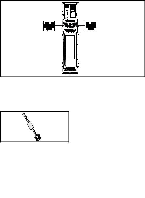
3.2Communications connections
The Unidrive M700/HS70 product offers Ethernet fieldbus communications and the Unidrive M701/ HS71 offers a 2 wire 485 serial interface. This enables the drive set-up, operation and monitoring to be carried out with a PC or controller if required.
Figure 3-2 Location of the communication connectors
1 |
8 |
1 |
8 |
3.2.1Ethernet Fieldbus communications (Unidrive M700/HS70 only)
The Unidrive M700/HS70 provides two RJ45 connections with an Ethernet switch for easy network creation.
3.2.2485 Serial communications (Unidrive M701/HS71 only)
The Unidrive M701/HS71 provides two parallel RJ45 connectors allowing easy daisy chaining. The drive supports the Modbus RTU protocol. See Table 3-3 for the connection details.
Figure 3-3 CT Comms cable
An isolated serial communications lead has been designed to connect the drive to IT equipment (such as laptop computers), and is available from the supplier of the drive. See below for details:
Table 3-2 Isolated serial comms lead details
Part number |
Description |
|
|
4500-0096 |
CT USB Comms cable |
The “isolated serial communications” lead has reinforced insulation as defined in IEC60950 for altitudes up to 3,000 m.
10 |
Unidrive M700/M701 / Unidrive HS70/HS71 Control Getting Started Guide |
|
Issue Number: 2 |
Table 3-3 |
Serial communication port pin-outs |
|
|
|
|
Pin |
|
Function |
1 |
|
120 Ω Termination resistor |
2 |
|
RX TX |
3 |
|
Isolated 0 V |
4 |
|
+24 V (100 mA) |
5 |
|
Isolated 0 V |
6 |
|
TX enable |
7 |
|
RX\ TX\ |
8 |
|
RX\ TX\ (if termination resistors are required, link to pin 1) |
Shell |
|
Isolated 0 V |
3.3Shield connections
The following guidelines should be followed to ensure suppression of radio-frequency emission and good noise immunity. It is particularly recommended that the guidelines for the encoder cable be followed closely in order to avoid disturbance to the encoder operation from electrical noise. Use the grounding bracket and grounding clamp supplied with the drive to terminate the shields at the drive.
Figure 3-4 Grounding of signal cable shields using the grounding bracket
Motor cable: Use a motor cable with an overall shield. Connect the shield of the motor cable to the ground terminal of the motor frame using a link that is as short as possible and not exceeding 50 mm (2 in) long. A full 360 ° termination of the shield to the terminal housing of the motor is beneficial.
Encoder cable: For best shielding use cable with an overall shield and individual shields on twisted pairs, connect the cable as illustrated in Figure 3-5. Clamp the overall shield to grounded metallic surfaces at both the encoder and the drive.
Brake resistor cable: The optional braking resistor should also be wired with shielded cable. If unshielded wire is required refer to the Drive User Guide for guidance.
Control cables: If the control wiring is to leave the enclosure, it must be shielded and the shield(s) clamped to the drive using the grounding bracket. Remove the outer insulating cover of the cable to ensure the shield(s) make contact with the bracket, but keep the shield(s) intact until as close as possible to the terminals.
<![endif]>information Further motor the Running parameters Basic started Getting connections Control Introduction connections Control 0) (Menu
Unidrive M700/M701 / Unidrive HS70/HS71 Control Getting Started Guide |
11 |
Issue Number: 2 |
|

Figure 3-5 Feedback cable shield connections
|
Twisted |
|
Twisted |
|
|
pair |
|
pair |
Shield |
Shield |
shield |
Cable |
shield |
|
connection |
|
|
connection |
|
to 0V |
|
|
|
to 0V |
Connection |
|
|
|
Connection |
at drive |
|
|
|
at motor |
|
Cable |
Ground clamp |
Cable |
|
|
shield |
shield |
|
|
|
|
on shield |
|
|
3.4Control connections
For information on control connections, refer to the back cover of this guide.
12 |
Unidrive M700/M701 / Unidrive HS70/HS71 Control Getting Started Guide |
|
Issue Number: 2 |

4 Getting started
4.1Quick start commissioning / start-up using Unidrive M Con-
nect (V02.00.00.00 onwards)
Unidrive M Connect is a Windows™ based software commissioning / start-up tool for Unidrive M/HS. Unidrive M Connect can be used for commissioning / start-up and monitoring, drive parameters can be uploaded, downloaded and compared and simple or custom menu listings can be created. Drive menus can be displayed in standard list format or as live block diagrams. Unidrive M Connect is able to communicate with a single drive or a network. Unidrive M Connect can be downloaded from www.controltechniques.com (file size approximately 100 MB).
Unidrive M Connect system requirements
•Windows 8, Windows 7 SP1, Windows Vista SP2, Windows XP SP3
•Minimum of 1280 x 1024 screen resolution with 256 colours
•Microsoft.Net Frameworks 4.0 (this is provided in the downloaded file)
•Note that you must have administrator rights to install Unidrive M Connect
Any previous copy of Unidrive M Connect should be uninstalled before proceeding with the installation (existing projects will not be lost). Included within Unidrive M Connect is the Parameter Reference Guide for Unidrive M700/701 and Unidrive HS70/HS71.
4.1.1Power-up the drive
1.Start Unidrive M Connect, and on the ‘Project Management’ screen select 'Scan serial RTU network' or 'Scan all connected drives’.
<![endif]>information Further motor the Running parameters Basic started Getting connections Control Introduction information Safety 0) (Menu
Unidrive M700/M701 / Unidrive HS70/HS71 Control Getting Started Guide |
13 |
Issue Number: 2 |
|

Select the discovered drive.
1
2 |
|
4 |
3
1.Select the ‘Online’ icon to connect with the drive. When a successful connection is made the icon will be highlighted orange.
2.Select ‘Set mode and region’.
If the required control mode is highlighted in the ‘Drive Settings’ dialog, then:
•Change the supply frequency, if required and select ‘Apply’, otherwise select ‘Cancel’.
•Select ‘Default parameters‘ from the Dashboard and in the ‘Default Parameters’ dialogue, select ‘Apply’
If the required control mode is not highlighted in the ‘Drive Settings’ dialog then:
•Select the required mode and supply frequency.
•Select ‘Apply’.
3.Select ‘Setup’ and perform the steps highlighted (dotted lines indicate a step which may not need to be performed (see below):
14 |
Unidrive M700/M701 / Unidrive HS70/HS71 Control Getting Started Guide |
|
Issue Number: 2 |

Action |
Detail |
Unidrive M Connect contains a database for induction motors and permanent magnet motors.
Motor Setup
Provision is also made to enter motor nameplate data.
The next section describes the use of the motor database for a Leroy Somer LSRPM motor used in RFC-S Sensorless mode.
This only needs to be performed in RFC-A (with feedback) mode
Set Pr 03.024 = Feedback (0) Enter:
•Encoder power supply in Pr. 03.036 = 5 V (0), 8 V (1) or 15 V (2). *
|
|
|
|
If output voltage from the encoder is >5 V, then the termination resistors must be |
|
NOTE |
|||
|
disabled Pr 03.039 to 0. * |
|||
|
|
|
|
|
|
|
|
|
|
Motor Feedback |
|
|
|
Setting the encoder voltage supply too high for the encoder could result in |
Setup |
|
|
|
damage to the feedback device. |
|
|
|
|
|
|
|
CAUTION |
|
|
|
|
|
|
|
•Drive encoder Lines Per Revolution (LPR) in Pr 03.034 (set according to encoder) *
•Drive encoder termination resistor setting in Pr 03.039: *
0= A-A\, B-B\ termination resistors disabled
1= A-A\, B-B\, termination resistors enabled
*mm is dependant on the slot into which the SI-Encoder module is installed (15 =Slot 1, 16 = Slot 2, 17 = Slot 3).
Analog I/O |
The motor thermistor can be selected in Pr 07.015. Refer to the parameter help for Pr 07.015 |
|
for further information. |
||
|
||
|
|
|
|
Enter the required Acceleration rate and Deceleration rate |
|
Ramps Setup |
Note: If a braking resistor is installed, set 'Ramp mode' to 'Fast'. Also ensure Pr 10.030 and |
|
Pr 10.031 and Pr 10.061 are set correctly, otherwise premature 'Brake R Too Hot' trips may |
||
|
||
|
be seen). |
|
|
|
|
Autotune |
Not required when using data from the motor database for a Leroy Somer LSRPM motor used |
|
in RFC-S Sensorless mode. |
||
|
4. Select 'Save parameters in drive' to perform a parameter save.
The drive is now ready to run.
<![endif]>information Further motor the Running parameters Basic started Getting connections Control Introduction information Safety 0) (Menu
Unidrive M700/M701 / Unidrive HS70/HS71 Control Getting Started Guide |
15 |
Issue Number: 2 |
|
Loading...