


Commander C200/C300
Step By Step Guide
Guide pas à pas Schritt-für-Schritt-Anleitung Guida dettagliata
Guía detallada
Frame sizes 5 to 9
Tailles 5 à 9
Baugrößen 5 bis 9
Taglie da 5 a 9
Tamaños 5 a 9

English
Introduction
The Commander C200 and C300 is a simple and flexible range of drives from 0.25 kW to 132 kW in 9 frame sizes and two input voltage ranges (200 V, and 400 V).
This Step-by Step guide provides simple step-by-step instructions on how to mount the drive, fuse and cable selection, wiring the drive-up, programming the drive and running the motor in analog input mode or keypad mode on frames 5 to 9.
Features of the drive
Figure 1-1 Feature diagram
128 |
129 |
10 |
|
|
6 |
|
|
|
|
|
12 |
|
|
|
|
12 |
|
12 |
|
|
|
|
|
|
|
|
|
|
|
|
|
|
|
1 |
L1 |
|
L2 |
L3 |
8 |
|
|
|
|
|
|||
|
|
|
PE |
+DC |
|
-DC |
|
|
|
|
5 |
|
|
|
9 |
|
|
|
|
|
|
|
1 |
7 |
|
12 |
|
|
|
|
|
|
|
|
|
|
|
|
|
5 |
6 |
|
7 8 |
9 |
|
|
|
|
|
3 |
|
|
|
||
|
|
|
77 |
|
|
41 42 |
2 |
|
|
|
|
|
|
|
3 |
|
|
13 |
|
|
|
|
|
6 |
|
|
|
|
|
|
4 |
|
|
|
|
|
|
|
13 |
|
|
5 |
|
|
|
|
|
5 |
|
|
U |
|
V |
W |
5 |
|
U V W |
|
|||||
|
|
|
|
+DC |
|
BRAKE |
|
|
|
|
5 |
|
|
|
|
|
4 |
|
|
8 |
|
10 |
|
|
|
|
|
|
|
||
|
|
11 |
|
|
|
|
11 |
Key |
|
|
|
|
|
|
|
1. Rating label |
|
|
2. Relay connections (Refer to Fig. 6-5) |
|
|||
3. Option module slot 1 |
4. Motor connections (Refer to Fig. 6-1 to Fig. 6-4) |
||||||
5. Ground connections (Refer to Fig. 6-1 to 6-4) |
6. AC supply connections (Refer to Fig. 6-1 to Fig. 6-4) |
||||||
7. Control connections (Refer to Fig. 6-5) |
8. DC bus + |
|
|
|
|
||
9. DC bus - |
|
|
10. Braking terminal |
|
|
|
|
11. Cable bracket to ground terminals |
12. Internal EMC filter screw* |
|
|||||
13.Safe Torque Off terminals (STO)** (Refer to Fig 6-5)
*Before removing the screw, refer to Chapter 4 in the Power Installation Guide.
**Commander C300 only
2 |
Commander C200/C300 Step By Step Guide |
|
Issue Number: 2 |

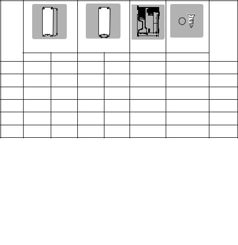
STEP 1: Check the contents of the box
Check you have all the components and your drive has not been damaged during transportation.
|
|
SAFETY |
|
|
KIT BOX* |
|
INFORMATION |
|
|
+ |
+ |
+ |
STEP BY STEP |
|
GUIDE |
||||
|
|
|
* With frame size 7, 8 and 9, surface mounting brackets are also supplied with the drive.
STEP 2: Check model and voltage
The model number can be found on the identification label |
1 on the top of the drive. Please check that the model |
||
and the drive voltage range is suitable for the installation. |
|
|
|
1 |
|
|
|
Derivative |
Electrical Specifications |
|
|
C300 - |
05 4 |
00270 |
A |
Product line: |
|
|
Drive Format : |
|
|
|
|
Frame size: |
|
|
A - AC in AC out |
|
|
E - AC in AC out (without internal choke) |
|
|
|
|
|
Voltage rating: |
|
Current Rating : |
|
|
|
|
|
2 - 200 V (200 - 240 ± 10 %) |
|
Heavy Duty current rating x10 |
|
4 - 400 V (380 - 480 ± 10 %) |
|
|
|
<![endif]>English
<![if ! IE]><![endif]>Français
<![if ! IE]><![endif]>Deutsch
<![if ! IE]><![endif]>Italiano
<![if ! IE]><![endif]>Español
Commander C200/C300 Step By Step Guide |
3 |
Issue Number: 2 |
|
STEP 3: Mount the drive
The drive should be mounted in an ambient temperature range of - 20 °C to 60 °C (- 4 °F to 140 °F).
Output current derating may be required at ambient temperatures >40 °C (104 °F). Refer to the relevant Power Installation Guide (section 5.1). For UL installations, the maximum ambient temperature permitted is 50 °C (122 °F) with any specified derating applied.
The drive can be screwed on a wall or Through-panel mounted (Refer to chapter 3 in the Power Installation Guide). Table 3-1 highlights the clearances.
Table 3-1 Recommended spacing
|
Spacing between drive |
Spacing between |
Spacing above |
Spacing below |
|
Frame size |
and enclosure / |
||||
drives |
drive |
drive |
|||
|
EMC filter |
||||
|
|
|
|
||
|
|
|
|
|
|
5 |
30 mm (1.18 in) |
0 mm (0.00 in) |
100 mm (4.0 in) |
100 mm (4.0 in) |
|
|
|
|
|
|
|
6 |
30 mm (1.18 in) |
0 mm (0.00 in) |
100 mm (4.0 in) |
100 mm (4.0 in) |
|
|
|
|
|
|
|
7 |
45 mm (1.77 in) |
30 mm (1.18 in) |
60 mm (2.37 in) |
100 mm (4.0 in) |
|
|
|
|
|
|
|
8 |
45 mm (1.77 in) |
30 mm (1.18 in) |
60 mm (2.37 in) |
100 mm (4.0 in) |
|
|
|
|
|
|
|
9 |
45 mm (1.77 in) |
60 mm (2.37 in) |
60 mm (2.37 in) |
100 mm (4.0 in) |
|
|
|
|
|
|
Frame |
|
|
|
|
|
|
Weight |
|
|
|
H |
|
W |
D |
Ø |
|
|
|
Mounting |
Overall |
Mounting |
Overall |
Overall |
Diameter |
|
|
5 |
375 mm |
391 mm |
106 mm |
143 mm |
200 mm |
6.5 mm (0.26 in) |
7.4 kg |
|
(14.76 in) |
(15.39 in) |
(4.17 in) |
(5.63 in) |
(7.87 in) |
(16.3 Ib) |
|||
|
|
|||||||
6 |
378 mm |
391 mm |
196 mm |
210 mm |
227 mm |
7.0 mm (0.28 in) |
14 kg |
|
(14.88 in) |
(15.39 in) |
(7.72 in) |
(8.27 in) |
(8.94 in) |
(30.9 Ib) |
|||
|
|
|||||||
7 |
538 mm |
557 mm |
220 mm |
270 mm |
280 mm |
9.0 mm (0.35 in) |
28 kg |
|
(21.18 in) |
(21.93 in) |
(8.66 in) |
(10.63 in) |
(11.02 in) |
(61.70 Ib) |
|||
|
|
|||||||
8 |
784 mm |
804 mm |
259 mm |
310 mm |
290 mm |
9.0 mm (0.35 in) |
52 kg |
|
(30.87 in) |
(31.65 in) |
(10.20 in) |
(12.21 in) |
(11.42 in) |
(114.6 Ib) |
|||
|
|
|||||||
9E |
1051 mm |
1069 mm |
259 mm |
310 mm |
290 mm |
9.0 mm (0.35 in) |
46 kg |
|
(41.38 in) |
(42.09 in) |
(10.20 in) |
(12.21 in) |
(11.42 in) |
(101.4 Ib) |
|||
|
|
|||||||
9A |
1090 mm |
1108 mm |
259 mm |
310 mm |
290 mm |
9.0 mm (0.35 in) |
66.5 kg |
|
(42.91 in) |
(43.62 in) |
(10.20 in) |
(12.21 in) |
(11.42 in) |
(146.6 Ib) |
|||
|
|
4 |
Commander C200/C300 Step By Step Guide |
|
Issue Number: 2 |
STEP 4: Select supply / motor cables and fuses
The supply/motor cables and fuses or MCB’s used should follow the ratings provided in the table below:
The voltage rating of fuses must be greater than or equal to the highest supply voltage of the system. Fuses: The AC supply to the drive must be installed with suitable protection against overload. Failure
to observe this requirement will cause risk of fire.
WARNING
|
Maximum |
Fuses |
|
|
Cables |
|
|
|
|
|
|
|
|
|
|
|
|
|
|
|
continuous |
IEC Class |
UL |
IEC60364-5-52 |
UL 508C |
||||
Model |
input |
Class CC, |
|||||||
|
current |
gG or gR |
J, or T* |
|
mm² |
AWG |
|||
|
A |
A |
A |
Input |
|
Output |
Input |
|
Output |
|
|
|
|
|
|
|
|
|
|
05200250 |
31 |
40 |
40 |
|
10 |
|
8 |
||
06200330 |
48.8 |
63 |
60 |
|
16 |
|
4 |
||
|
|
|
|
|
|
|
|
||
06200440 |
56.6 |
63 |
70 |
|
25 |
|
3 |
||
|
|
|
|
|
|
|
|
||
05400270 |
29 |
40 |
35 |
|
6 |
|
8 |
||
05400300 |
29 |
40 |
35 |
|
6 |
|
8 |
||
|
|
|
|
|
|
|
|
||
06400350 |
36 |
63** |
40 |
|
10 |
|
6 |
||
|
|
|
|
|
|
|
|
||
06400420 |
46 |
63** |
50 |
|
16 |
|
4 |
||
|
|
|
|
|
|
|
|
||
06400470 |
60 |
63** |
70 |
|
25 |
|
3 |
||
07200610 |
67 |
80 |
80 |
|
35 |
|
2 |
||
07200750 |
84 |
100 |
100 |
|
35 |
|
1 |
||
|
|
|
|
|
|
|
|
||
07200830 |
105 |
125 |
125 |
|
70 |
|
1/0 |
||
|
|
|
|
|
|
|
|
||
08201160 |
137 |
200** |
200*** |
|
95 |
|
3/0 |
||
|
|
|
|
|
|
|
|||
08201320 |
166 |
200** |
225*** |
2 x 70 |
|
2 x 1 |
|||
|
|
|
|
|
|
|
|
||
09201760 |
205 |
250** |
250*** |
2 x 70 (B1) |
|
2 x 95 (B2) |
2 x 2/0 |
||
|
|
|
|
|
|
|
|
||
09202190 |
260 |
315** |
300*** |
2 x 95 (B1) |
|
2 x 120 (B2) |
2 x 4/0 |
||
|
|
|
|
|
|
|
|
|
|
07400660 |
74 |
100 |
80 |
|
35 |
|
1 |
||
07400770 |
88 |
100 |
100 |
|
50 |
|
2 |
||
|
|
|
|
|
|
|
|
||
07401000 |
105 |
125 |
125 |
|
70 |
|
1/0 |
||
|
|
|
|
|
|
|
|||
08401340 |
155 |
250** |
225*** |
2 x 50 |
|
2 x 1 |
|||
|
|
|
|
|
|
||||
08401570 |
177 |
250** |
225*** |
2 x 70 |
2 x 1/0 |
||||
|
|
|
|
|
|
|
|
|
|
09402000 |
232 |
315** |
300*** |
2 x 70 (B1) |
|
2 x 95 (B2) |
2 x 3/0 |
|
2 x 2/0 |
09402240 |
267 |
315** |
350*** |
2 x 95 (B1) |
|
2 x 120 (B2) |
2 x |
4/0 |
|
|
|
|
|
|
|
|
|
|
|
*These fuses are fast acting.
**These fuses are class gR.
***These fuses are class HSJ.
NOTE |
The product is UL listed for use on a circuit up to 100 kA maximum supply symmetrical fault current, |
|
when protected by fuses. |
||
|
||
NOTE |
IEC cable sizes assume Copper conductor, PVC insulation, Installation method B2 and ambient |
|
temperature of 40 °C (104 °F). UL cable sizes assume Copper conductor with insulation rated at 75 °C |
||
|
||
|
(167 °F). |
<![endif]>English
<![if ! IE]><![endif]>Français
<![if ! IE]><![endif]>Deutsch
<![if ! IE]><![endif]>Italiano
<![if ! IE]><![endif]>Español
Commander C200/C300 Step By Step Guide |
5 |
Issue Number: 2 |
|
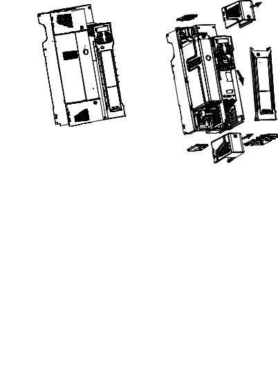
Table 4-1 Protective ground cable ratings
Input phase conductor size |
Minimum ground conductor size |
|
|
|
|
≤ 10 mm² |
Either 10 mm² or two conductors of the same cross-sectional area as the input |
|
phase conductor |
||
|
||
|
|
|
> 10 mm² and ≤ 16 mm² |
The same cross-sectional area as the input phase conductor |
|
|
|
|
> 16 mm² and ≤ 35 mm² |
16 mm² |
|
|
|
|
> 35 mm² |
Half of the cross-sectional area of the input phase conductor |
|
|
|
STEP 5: Remove the terminal cover and finger guard breakouts
1.Using a flat bladed screwdriver, turn the terminal cover locking clip anti-clockwise by approximately 30°.
2.Slide the terminal cover down.
3.Remove terminal cover in direction shown.
1
2
3
6 |
Commander C200/C300 Step By Step Guide |
|
Issue Number: 2 |
 Loading...