


User Guide
Commander SE
Sizes 1 to 4
Variable speed drive for 3 phase induction motors from 0.25kW to 15kW
Part No. 0452-0033
Issue Number: 5
www.controltechniques.com

General Information
The manufacturer accepts no liability for any consequences resulting
from inappropriate, negligent or incorrect installation or adjustment of the optional operating parameters of the equipment or from mismatching the
variable speed drive (Drive) with the motor.
WARNING
The contents of this User Guide are believed to be correct at the time of printing. In the interests of a commitment to a policy of continuous development and improvement, the manufacturer reserves the right to change the specification of the product or its performance, or the contents of the User Guide, without notice.
All rights reserved. No parts of this User Guide may be reproduced or transmitted in any form or by any means, electrical or mechanical including photocopying, recording or by an information storage or retrieval system, without permission in writing from the publisher.
IMPORTANT
Drive software version
This product is supplied with the latest version of user-interface and machine control software. If this product is to be used in a new or existing system with other Commander SE Drives, there may be some differences between their software and the software in this product. These differences may cause this product to function differently. This may also apply to Drives returned from a Control Techniques Service Centre.
If there is any doubt, contact a Control Techniques Drive Centre.
Copyright |
© August 2000 Control Techniques Drives Limited |
Issue Code: |
5 |
Software: |
V01.08.00 onwards |
|
Commander SE User Guide |
|
Issue Number 5 |
|
|

Contents
1 |
Safety Information |
3 |
1.1 |
Warnings, Cautions and notes |
3 |
1.2 |
Electrical safety - general warning |
3 |
1.3 |
System design and safety of personnel |
3 |
1.4 |
Environmental limits |
4 |
1.5 |
Compliance with regulations |
4 |
1.6 |
Motor |
4 |
1.7 |
Adjusting parameters |
4 |
2 |
Options |
5 |
3 |
Technical Data |
6 |
3.1 |
Power dependant rating data |
6 |
3.2 |
General data |
13 |
3.3 |
RFI Filters |
15 |
4 |
Installing the Drive |
17 |
4.1 |
Safety information |
17 |
4.2 |
Planning the installation |
17 |
4.3 |
Mechanical installation |
19 |
4.4 |
Electrical installation |
23 |
4.5 |
Electromagnetic compatibility (EMC) |
27 |
5 |
Terminals |
35 |
5.1 |
Power terminal connections |
35 |
5.2 |
Control terminal connections |
36 |
5.3 |
Serial communication connections |
37 |
5.4 |
Control terminal specifications |
38 |
Commander SE User Guide
Issue Number 5

6 |
Handling and Programming |
42 |
6.1 |
Display and keypad |
42 |
6.2 |
Display Messages |
43 |
6.3 |
Selecting and changing parameters |
44 |
6.4 |
Saving parameters |
45 |
6.5 |
Security codes |
45 |
6.6 |
Setting a security code |
45 |
6.7 |
Unlocking a security code |
45 |
6.8 |
Set security back to zero (0) - no security |
46 |
6.9 |
Setting to default values |
46 |
6.10 |
Level 1 and level 2 parameter descriptions |
46 |
7 |
Getting Started - Bench Testing |
67 |
7.1 |
Terminal control |
67 |
7.2 |
Keypad control |
69 |
8 |
Diagnostics and Protective Features |
71 |
8.1 |
Trip codes |
71 |
8.2 |
Alarm warnings |
73 |
8.3 |
HF-Hardware fault trip codes |
73 |
9 |
Parameter List |
74 |
10 |
Advanced Functions |
75 |
10.1 |
Speed control |
75 |
10.2 |
Ramps |
75 |
10.3 |
Torque control |
75 |
10.4 |
Stopping |
75 |
10.5 |
Programmable I/O |
75 |
10.6 |
Motor protection |
75 |
10.7 |
Monitoring |
75 |
10.8 |
Auxiliary functions |
75 |
10.9 |
Second motor selection |
75 |
11 |
UL Listing Information |
76 |
11.1 |
Common UL information |
76 |
11.2 |
Power dependant UL information |
76 |
Commander SE User Guide
Issue Number 5

Declaration of Conformity
Control Techniques, The Gro, Newtown, Powys, UK. SY16 3BE
SE11200025 |
SE11200037 |
SE11200055 |
SE11200075 |
|
|
|
|
SE2D200075 |
SE2D200110 |
SE2D200150 |
SE2D200220 |
|
|
|
|
SE23200400 |
|
SE23400075 |
SE23400110 |
SE23400150 |
SE23400220 |
SE23400300 |
SE23400400 |
|
|
|
|
SE33200550 |
SE33400550 |
SE33200750 |
SE33400750 |
|
|
|
|
SE43401100 |
SE43401500 |
|
|
|
|
|
|
The AC variable speed drive products listed above, have been designed and manufactured in accordance with the following European harmonised, national and international standards:
EN60249 |
Base materials for printed circuits |
|
|
IEC326-1 |
Printed boards: general information for the specification writer |
|
|
IEC326-5 |
Printed boards: specification for singleand double-sided printed boards |
|
with plated-through holes |
|
|
IEC326-6 |
Printed boards: specification for multilayer printed boards |
|
|
IEC664-1 |
Insulation co-ordination for equipment within low-voltage systems: |
|
principles, requirements and tests |
|
|
EN60529 |
Degrees of protection provided by enclosures (IP code) |
|
|
UL94 |
Flammability rating of plastic materials |
|
|
UL508C |
Standard for power conversion equipment |
|
|
*EN50081-1 |
Generic emission standard for the residential, commercial and light |
|
industrial environment |
|
|
EN50081-2 |
Generic emission standard for the industrial environment |
|
|
EN50082-2 |
Generic immunity standard for the industrial environment |
|
|
EN61800-3 |
Adjustable speed electrical power drive systems - Part 3: EMC product |
|
standard including specific test methods |
|
|
*Applies to Size 1 units only.
These products comply with the Low Voltage Directive 73/23/EEC, the Electromagnetic Compatibility (EMC) Directive 89/336/EEC and the CE Marking Directive 93/68/EEC.
W. Drury
Executive VP Technology
Date: 8th March 2000
These electronic Drive products are intended to be used with appropriate motors, controllers, electrical protection components and other equipment to form complete end products or systems. Compliance with safety and EMC regulations depends upon installing and configuring Drives correctly, including using the specified input filters. The Drives must be installed only by professional assemblers who are familiar with requirements for safety and EMC. The assembler is responsible for ensuring that the end product or system complies with all the relevant laws in the country where it is to be used. Refer to this User Guide. A Commander SE EMC Data Sheet is also available giving detailed EMC information.
Commander SE User Guide |
1 |
Issue Number 5 |
2 |
Commander SE User Guide |
Issue Number 5 |
|
|
|

1 |
Safety Information |
1.1Warnings, Cautions and notes
A Warning contains information which is essential for avoiding a safety hazard.
WARNING
A Caution contains information which is necessary for avoiding a risk of damage to the product or other equipment.
CAUTION
NOTE
A Note contains information which helps to ensure correct operation of the product.
1.2Electrical safety - general warning
The voltages used in the Drive can cause severe electrical shock and/or burns, and could be lethal. Extreme care is necessary at all times when working with or adjacent to the Drive.
Specific warnings are given at the relevant places in this User Guide.
1.3System design and safety of personnel
The Drive is intended as a component for professional incorporation into complete equipment or a system. If installed incorrectly, the Drive may present a safety hazard. The Drive uses high voltage and currents, carries a high level of stored electrical energy, and is used to control equipment which can cause injury.
Close attention is required to the electrical installation and the system design to avoid hazards, either in normal operation or in the event of equipment malfunction. System design, installation, commissioning and maintenance must be carried out by personnel who have the necessary training and experience. They must read this safety information and this User Guide carefully.
The STOP function of the Drive does not remove dangerous voltages from the output of the Drive or from any external option unit.
Careful consideration must be given to the functions of the Drive which might result in a hazard, either through their intended functions or through incorrect operation due to a fault.
In any application where a malfunction of the Drive could lead to damage, loss or injury, a risk analysis must be carried out, and where necessary, further measures taken to reduce the risk.
The STOP and START controls or electrical inputs of the Drive must not be relied upon to ensure safety of personnel. If a safety hazard could exist from unexpected starting of the Drive, an interlock that
Commander SE User Guide |
3 |
Issue Number 5 |
electrically isolates the Drive from the AC supply must be installed to prevent the motor being inadvertently started.
To ensure mechanical safety, additional safety devices such as electromechanical interlocks and overspeed protection devices may be required. The Drive must not be used in a safety critical application without additional high integrity protection against hazards arising from a malfunction.
Under certain conditions, the Drive can suddenly discontinue control of the motor. If the load on the motor could cause the motor speed to be increased (e.g. in hoists and cranes), a separate method of braking and stopping must be used (e.g. a mechanical brake).
1.4Environmental limits
Instructions in this User Guide regarding transport, storage, installation and use of the Drive must be complied with, including the specified environmental limits. Drives must not be subjected to excessive physical force.
1.5Compliance with regulations
The installer is responsible for complying with all relevant regulations, such as national wiring regulations, accident prevention regulations and electromagnetic compatibility (EMC) regulations. Particular attention must be given to the cross-sectional areas of conductors, the selection of fuses or other protection, and protective earth (ground) connections. This User Guide contains instruction for achieving compliance with specific EMC standards.
Within the European Union, all machinery in which this product is used must comply with the following directives:
•97/37/EC: Safety of machinery.
•89/336/EEC: Electromagnetic Compatibility.
1.6Motor
Ensure the motor is installed in accordance with the manufacturer’s recommendations. Ensure the motor shaft is not exposed.
Standard squirrel cage induction motors are designed for single speed operation. If it is intended to use the capability of the Drive to run a motor at speeds above its designed maximum, it is strongly recommended that the manufacturer is consulted first.
Low speeds may cause the motor to overheat because the cooling fan becomes less effective. The motor should be fitted with a protection thermistor. If necessary, an electric forced vent fan should be used.
1.7Adjusting parameters
Some parameters have a profound effect on the operation of the Drive. They must not be altered without careful consideration of the impact on the controlled system. Measures must be taken to prevent unwanted changes due to error or tampering.
4 |
Commander SE User Guide |
Issue Number 5 |
|
|
|

2 Options
The following options are available for Commander SE;
•Quickey for rapid parameter transfer (SE55)
•Standard and low earth leakage footprint / side mounting RFI filters and low cost panel mounting RFI filters
•Universal Keypad, IP65, hand held or door mounting plain text, LCD display
•SE Soft Windows™ based set-up software for advanced programming
•+10V to -10V analog input card for bi-directional input reference (SE51)
•Cable screening bracket and screening clamps to provide a convenient way of connecting supply, motor and control cable screens to ground (SE11, 12, 13 & 14)
•EMC Data Sheets
•Through hole mounting plate drawings to allow heatsink to be put outside main cubicle
•EIA232 to EIA485 (2 wire) converter for connecting between the Drive and PC when using SE Soft (SE71 Communications lead)
•Fieldbus Communications:
Profibus DP (SE73)
Device Net (SE77)
CAN Open (SE77)
Interbus (SE74)
CT Net (SE75)
•Commander SE Advanced User Guide: (See Chapter 10 of this User Guide for a list of advanced functions).
•AC input line reactors
•Braking resistors and mounting plate
For further details on the above options and availability, contact your local Control Techniques Drive Centre or Distributor.
Commander SE User Guide |
5 |
Issue Number 5 |

3 |
Technical Data |
3.1Power dependant rating data Model code explanation
SE1 - frame size 1, SE2 - frame size 2, SE3 - frame size 3, SE4 - frame size 4.
1 - single phase, D - Dual rating (single and three phase), 3 - three phase 2 - 230VAC nominal input voltage, 4 - 400VAC nominal input voltage 00 - for expansion of Drive power range
025 to 1500 - 0.25 kW to 15 kW output power
Table 3.1 Commander SE Size 1
MODEL |
|
|
SE11200... |
|
||
|
025 |
|
037 |
|
055 |
075 |
AC supply voltage and frequency |
Single phase 200 - 240V +/- 10% 48 - 62Hz |
|||||
Input displacement factor (cos f) |
|
|
|
>0.97 |
|
|
Nominal motor power - kW |
0.25 |
|
0.37 |
|
0.55 |
0.75 |
Nominal motor power - HP |
|
|
0.50 |
|
|
1.0 |
Output voltage and frequency |
3 phase, |
0 to input |
voltage, 0 to |
1000Hz |
||
|
|
|
|
|
|
|
100% RMS output current - A |
1.5 |
|
2.3 |
|
3.1 |
4.3 |
|
|
|
|
|
|
|
150% overload current for 60 secs - A |
2.3 |
|
3.5 |
|
4.7 |
6.5 |
|
|
|
|
|
|
|
Typical full load input current - A* |
5.6 |
|
6.5 |
|
8.8 |
11.4 |
Typical inrush current - A** (duration <10ms) |
|
|
|
100 |
|
|
Drive power losses at 230VAC at 6kHz switching |
|
|
|
|
|
|
frequency - W |
18 |
|
24 |
|
37 |
56 |
|
|
|
|
|
|
|
Weight - kg/lb |
|
1.1/2.4 |
|
1.25/2.75 |
||
|
|
|
|
|
|
|
Cooling fan fitted |
|
|
|
No |
|
|
*See section 3.1.1.
**For an explanation of inrush current, see section 3.1.2.
Table 3.2 Recommended supply fuses and cables
MODEL |
|
|
SE11200... |
|
|
||
|
|
025 |
037 |
|
055 |
|
075 |
Recommended input supply fuse - A |
|
6 |
10 |
|
|
16 |
|
Control cable |
mm² |
|
|
³ |
0.5 |
|
|
|
AWG |
|
|
20 |
|
|
|
Recommended input cable |
mm² |
|
1.0 |
|
|
|
1.5 |
|
|
|
|
|
|
|
|
|
AWG |
|
16 |
|
|
|
14 |
|
|
|
|
|
|
|
|
Recommended motor cable |
mm² |
|
|
1.0 |
|
|
|
|
|
|
|
|
|
|
|
|
AWG |
|
|
16 |
|
|
|
6 |
Commander SE User Guide |
Issue Number 5 |
|
|
|
Table 3.3 Commander SE Size 2, 200V dual rated units
MODEL |
|
|
|
SE2D200... |
|
|
|
|||
|
075 |
|
110 |
150 |
|
220 |
||||
AC supply voltage and frequency |
Single or 3 phase 200 to 240V +/- 10%, 48 |
|||||||||
|
|
|
|
|
to 62Hz |
|
|
|
||
|
|
|
|
|
|
|
|
|||
Input displacement factor (cos f) |
|
|
>0.97 |
|
|
|
|
|||
Nominal motor power - kW |
0.75 |
|
1.1 |
1.5 |
|
2.2 |
||||
Nominal motor power - HP |
1.0 |
|
|
|
2.0 |
|
3.0 |
|||
Output voltage and frequency |
3 phase, |
0 to input |
voltage, 0 to |
1000Hz |
||||||
100% RMS output current - A |
4.3 |
|
5.8 |
7.5 |
|
10.0 |
||||
150% overload current for 60 secs - A |
6.5 |
|
8.7 |
11.3 |
|
15.9 |
||||
Typical full load input current - A* 1ph/3ph |
11.0 |
5.5 |
|
15.1 |
7.9 |
19.3 |
9.6 |
|
26.2 |
13.1 |
|
|
|
|
|
|
|
|
|
|
|
Typical inrush current - A**(duration <10ms) |
|
|
55 |
|
|
|
35 |
|
||
|
|
|
|
|
|
|
|
|
|
|
Drive power losses at 230VAC at 6kHz switching |
|
|
|
|
|
|
|
|
|
|
frequency - W |
54 |
|
69 |
88 |
|
125 |
||||
|
|
|
|
|
|
|
|
|
|
|
Weight - kg/lb |
|
|
|
2.75 |
/ 6 |
|
|
|
|
|
Cooling fan fitted |
|
|
No |
|
Yes |
|||||
*See section 3.1.1.
**For an explanation of inrush current, see section 3.1.2.
Table 3.4 Recommended supply fuses and cables
MODEL |
|
|
|
|
SE2D200... |
|
|
|
|
||||
|
|
075 |
110 |
|
150 |
220 |
|||||||
|
|
1ph |
3ph |
1ph |
3ph |
1ph |
3ph |
1ph |
3ph |
||||
Recommended input supply fuse - A |
|
16 |
10 |
20 |
|
16 |
|
25 |
|
16 |
32 |
|
20 |
|
|
|
|
|
|
|
|
|
|
|
|
|
|
Control cable |
mm² |
|
|
|
|
³ |
0.5 |
|
|
|
|
|
|
|
AWG |
|
|
|
|
|
20 |
|
|
|
|
|
|
Recommended input cable |
mm² |
1.5 |
1.0 |
2.5 |
|
1.5 |
|
2.5 |
|
1.5 |
4.0 |
|
2.5 |
|
AWG |
14 |
16 |
12 |
|
14 |
|
12 |
|
14 |
10 |
|
12 |
|
|
|
|
|
|
|
|
|
|
|
|
||
Recommended motor cable |
mm² |
|
|
1.0 |
|
|
|
|
1.5 |
||||
|
|
|
|
|
|
|
|
|
|
|
|
||
|
AWG |
|
|
|
16 |
|
|
|
|
|
14 |
||
|
|
|
|
|
|
|
|
|
|
||||
Recommended braking resistor cable |
mm² |
|
|
1.0 |
|
|
|
|
1.5 |
||||
|
AWG |
|
|
|
16 |
|
|
|
|
|
14 |
||
Table 3.5 Braking resistors
MODEL |
|
|
SE2D200... |
|
|
|
075 |
|
110 |
150 |
220 |
Minimum braking resistor value - W |
|
|
50 |
|
40 |
Recommended braking resistor value - W |
|
100 |
75 |
50 |
|
Maximum braking current - A |
|
9 |
|
11 |
|
Resistor peak power rating - kW |
|
1.8 |
2.4 |
3.5 |
|
NOTE
Before fitting a braking resistor please read the information on Braking, and the Warnings on High Temperatures and Overload Protection at the end of this section.
Commander SE User Guide |
7 |
Issue Number 5 |

Table 3.6 Commander SE Size 2, 200V Three phase units
MODEL |
SE23200400 |
AC supply voltage and frequency |
3 phase 200 to 240V +/- 10%, 48 to 62Hz |
Input displacement factor (cos f) |
>0.97 |
Nominal motor power - kW |
4 |
Nominal motor power - HP |
5 |
|
|
Output voltage and frequency |
3 phase, 0 to input voltage, 0 to 1000Hz |
|
|
100% RMS output current - A |
17.0 |
|
|
150% overload current for 60 secs - A |
25.5 |
|
|
Typical full load input current - A* |
21 |
Typical inrush current - A** (duration <10ms) |
35 |
Drive power losses at 230VAC at 6kHz switching |
|
frequency - W |
174 |
|
|
Weight - kg/lb |
2.75 / 6 |
|
|
Cooling fan fitted |
Yes |
*See section 3.1.1.
**For an explanation of inrush current, see section 3.1.2.
Table 3.7 Recommended supply fuses and cables
MODEL |
|
SE23200400 |
Recommended input supply fuse - A |
|
32 |
Control cable |
mm² |
³ 0.5 |
|
AWG |
20 |
|
|
|
Recommended input cable |
mm² |
4.0 |
|
|
|
|
AWG |
10 |
|
|
|
Recommended motor cable |
mm² |
2.5 |
|
AWG |
12 |
Recommended braking resistor cable |
mm² |
2.5 |
|
AWG |
12 |
Table 3.8 Braking resistors
MODEL |
SE23200400 |
Minimum braking resistor value - W |
30 |
Recommended braking resistor value - W |
30 |
Maximum braking current - A |
14 |
|
|
Resistor peak power rating - kW |
5.9 |
NOTE
Before fitting a braking resistor please read the information on Braking, and the Warnings on High Temperatures and Overload Protection at the end of this section.
8 |
Commander SE User Guide |
Issue Number 5 |
|
|
|

Table 3.9 Commander SE Size 2, 400V Three phase units
MODEL |
|
|
|
|
SE23400... |
|
|
|
|
075 |
|
110 |
150 |
220 |
300 |
400 |
|
AC supply voltage and frequency |
|
3 phase 380 to 480V +/- 10%, 48 to |
||||||
|
|
|
|
|
62Hz |
|
|
|
|
|
|
|
|
|
|
|
|
Input displacement factor (cos f) |
|
|
|
|
>0.97 |
|
|
|
Nominal motor power - kW |
0.75 |
|
1.1 |
1.5 |
2.2 |
3.0 |
4.0 |
|
Nominal motor power - HP |
1.0 |
|
|
2.0 |
3.0 |
|
5.0 |
|
Output voltage and frequency |
|
3 phase, 0 to |
input |
voltage, |
0 to |
1000Hz |
||
100% RMS output current - A |
2.1 |
|
3.0 |
4.2 |
5.8 |
7.6 |
9.5 |
|
150% overload current for 60 secs - A |
3.2 |
|
4.5 |
6.3 |
8.7 |
11.4 |
14.3 |
|
Typical full load input current - A*400V, 50Hz/480V, 60Hz |
3.6 |
|
4.8 |
6.4 |
9.3 |
11 |
14 |
|
|
|
|
|
|
|
|
|
|
Typical inrush current - A** (duration <10ms) |
|
|
|
90 |
|
|
60 |
|
|
|
|
|
|
|
|
|
|
Drive power losses at 480VAC at 6kHz switching |
|
|
|
|
|
|
|
|
frequency - W |
43 |
|
57 |
77 |
97 |
122 |
158 |
|
|
|
|
|
|
|
|
|
|
Weight - kg/lb |
|
|
|
|
2.75 |
/ 6 |
|
|
Cooling fan fitted |
|
No |
|
|
Yes |
|
||
*See section 3.1.1.
**For an explanation of inrush current, see section 3.1.2.
Table 3.10 Recommended fuses and cables
MODEL |
|
|
|
SE23400... |
|
|
|||
|
|
075 |
110 |
150 |
|
220 |
|
300 |
400 |
Recommended input supply fuse - A |
|
|
10 |
|
|
16 |
|
20 |
|
|
|
|
|
|
|
|
|
|
|
Control cable |
mm² |
|
|
³ |
0.5 |
|
|
|
|
|
AWG |
|
|
|
20 |
|
|
|
|
Recommended input cable |
mm² |
|
1.0 |
|
|
1.5 |
|
2.5 |
|
|
AWG |
|
16 |
|
|
14 |
|
12 |
|
Recommended motor cable |
mm² |
|
|
1.0 |
|
|
|
|
1.5 |
|
|
|
|
|
|
|
|
|
|
|
AWG |
|
|
16 |
|
|
|
|
14 |
|
|
|
|
|
|
|
|
|
|
Recommended braking resistor cable |
mm² |
|
|
|
1.5 |
|
|
|
|
|
|
|
|
|
|
|
|
|
|
|
AWG |
|
|
|
14 |
|
|
|
|
Table 3.11 Braking Resistors
MODEL |
|
|
SE23400... |
|
|
|
|
075 |
110 |
150 |
220 |
300 |
400 |
Minimum braking resistor value - W |
|
100 |
|
|
75 |
|
Recommended braking resistor value - W |
|
200 |
|
|
100 |
|
Maximum braking current - A |
|
10 |
|
|
12.5 |
|
Resistor peak power rating - kW |
|
3.4 |
|
|
6.9 |
|
NOTE
Before fitting a braking resistor please read the information on Braking, and the Warnings on High Temperatures and Overload Protection at the end of this section.
Commander SE User Guide |
9 |
Issue Number 5 |

Table 3.12 Commander SE Size 3, 200V units
MODEL |
|
SE33200... |
|
|
550 |
|
750 |
AC supply voltage and frequency |
3 phase 200 to 240V |
+/-10%, 48 to 62Hz |
|
Input displacement factor (cos φ) |
|
>0.97 |
|
Nominal motor power - kW |
5.5 |
|
7.5 |
|
|
|
|
Nominal motor power - HP |
7.5 |
|
10.0 |
|
|
|
|
Output voltage and frequency |
3 phase, 0 to input |
voltage, 0 to 1000Hz |
|
|
|
|
|
100% RMS output current - A |
25.0 |
|
28.5 |
|
|
|
|
150% overload current for 60 secs - A |
37.5 |
|
42.8 |
Typical full load input current - A* |
22.8 |
|
24.6 |
Typical inrush current - A** (duration <10ms) |
|
44 |
|
Drive power losses at 230VAC at 6kHz switching |
230 |
|
305 |
frequency - W |
|
|
|
|
|
|
|
Weight - kg/lb |
|
6 / |
13.2 |
|
|
|
|
Cooling fan fitted |
|
Yes |
|
*See section 3.1.1.
**For an explanation of inrush current, see section 3.1.2.
Table 3.13 Recommended fuses and cables
MODEL |
|
|
SE33200... |
|
|
|
550 |
|
750 |
Recommended input supply fuse - A |
|
|
30 |
|
|
|
|
|
|
Control cable |
mm² |
|
>0.5 |
|
|
|
|
|
|
|
AWG |
|
20 |
|
|
|
|
|
|
Recommended input cable |
mm² |
|
4.0 |
|
|
AWG |
|
10 |
|
Recommended motor cable |
mm² |
|
4.0 |
|
|
AWG |
|
10 |
|
Recommended braking resistor cable |
mm² |
|
4.0 |
|
|
AWG |
|
10 |
|
|
|
|
|
|
Table 3.14 Braking Resistors
MODEL |
|
SE33200... |
|
|
550 |
|
750 |
Minimum braking resistor value - Ω |
|
11.0 |
|
|
|
|
|
Recommended braking resistor value - Ω |
|
15.0 |
|
|
|
|
|
Maximum braking current - A |
|
28.0 |
|
Resistor peak power rating - kW |
|
11.8 |
|
NOTE
Before fitting a braking resistor please read the information on Braking, and the Warnings on High Temperatures and Overload Protection at the end of this section.
10 |
Commander SE User Guide |
Issue Number 5 |
|
|
|

Table 3.15 Commander SE Size 3, 400V units
MODEL |
|
SE33400... |
|
|
550 |
|
750 |
AC supply voltage and frequency |
3 phase 380 to 480V |
+/-10%, 48 to 62Hz |
|
Input displacement factor (cos φ) |
|
>0.97 |
|
Nominal motor power - kW |
5.5 |
|
7.5 |
|
|
|
|
Nominal motor power - HP |
7.5 |
|
10.0 |
|
|
|
|
Output voltage and frequency |
3 phase, 0 to input |
voltage, 0 to 1000Hz |
|
|
|
|
|
100% RMS output current - A |
13.0 |
|
16.5 |
|
|
|
|
150% overload current for 60 secs - A |
19.5 |
|
24.8 |
Typical full load input current - A* |
13.0 |
|
15.4 |
Typical inrush current - A** (duration <10ms) |
|
80 |
|
Drive power losses at 230VAC at 6kHz switching |
190 |
|
270 |
frequency - W |
|
|
|
|
|
|
|
Weight - kg/lb |
|
6 / |
13.2 |
|
|
|
|
Cooling fan fitted |
|
Yes |
|
*See section 3.1.1.
**For an explanation of inrush current, see section 3.1.2.
Table 3.16 Recommended fuses and cables
MODEL |
|
|
SE33400... |
|
|
|
550 |
|
750 |
Recommended input supply fuse - A |
|
16 |
|
20 |
|
|
|
|
|
Control cable |
mm² |
|
>0.5 |
|
|
|
|
|
|
|
AWG |
|
20 |
|
|
|
|
|
|
Recommended input cable |
mm² |
|
2.5 |
|
|
AWG |
|
12 |
|
Recommended motor cable |
mm² |
|
2.5 |
|
|
AWG |
|
12 |
|
Recommended braking resistor cable |
mm² |
|
2.5 |
|
|
AWG |
|
12 |
|
|
|
|
|
|
Table 3.17 Braking Resistors
MODEL |
|
SE33400... |
|
|
550 |
|
750 |
Minimum braking resistor value - Ω |
|
33.0 |
|
|
|
|
|
Recommended braking resistor value - Ω |
|
50 |
|
|
|
|
|
Maximum braking current - A |
|
16.6 |
|
Resistor peak power rating - kW |
|
13.8 |
|
NOTE
Before fitting a braking resistor please read the information on Braking, and the Warnings on High Temperatures and Overload Protection at the end of this section.
Commander SE User Guide |
11 |
Issue Number 5 |

Table 3.18 Commander SE Size 4, 400V units
MODEL |
|
SE4340... |
|
|
1100 |
|
1500 |
AC supply voltage and frequency |
3 phase 380 to 480V |
+/-10%, 48 to 62Hz |
|
Input displacement factor (cosφ) |
|
>0.97 |
|
Nominal motor power - kW |
11 |
|
15 |
|
|
|
|
Nominal motor power - HP |
15 |
|
20 |
|
|
|
|
Output voltage and frequency |
3 phase, 0 to input |
voltage, 0 to 1000Hz |
|
|
|
|
|
100% RMS output current - A |
24.5 |
|
30.5 |
|
|
|
|
150% overload current for 60 secs - A |
36.75 |
|
45.75 |
Typical full load input current - A* |
23 |
|
27.4 |
Typical inrush current - A** (duration <10ms) |
|
40 |
|
Drive power losses at 230VAC at 6kHz switching |
400 |
|
495 |
frequency - W |
|
|
|
|
|
|
|
Weight - kg/lb |
|
11 / |
24.2 |
|
|
|
|
Cooling fan fitted |
|
Yes |
|
*See section 3.1.1.
**For an explanation of inrush current, see section 3.1.2.
Table 3.19 Recommended fuses and cables
MODEL |
|
|
SE4340... |
|
|
|
1100 |
|
1500 |
Recommended input supply fuse - A |
|
32 |
|
40 |
|
|
|
|
|
Control cable |
mm² |
|
>0.5 |
|
|
|
|
|
|
|
AWG |
|
20 |
|
|
|
|
|
|
Recommended input cable |
mm² |
|
4.0 |
|
|
AWG |
|
10 |
|
Recommended motor cable |
mm² |
4.0 |
|
6.0 |
|
AWG |
10 |
|
8 |
Recommended braking resistor cable |
mm² |
|
6.0 |
|
|
AWG |
|
8 |
|
|
|
|
|
|
Table 3.20 Braking Resistors
MODEL |
|
SE4340... |
|
|
1100 |
|
1500 |
Minimum braking resistor value - Ω |
|
27 |
|
|
|
|
|
Recommended braking resistor value - Ω |
40 |
|
30 |
|
|
|
|
Maximum braking current - A |
|
30 |
|
Resistor peak power rating - kW |
|
25.5 |
|
NOTE
Before fitting a braking resistor please read the information on Braking, and the Warnings on High Temperatures and Overload Protection at the end of this section.
12 |
Commander SE User Guide |
Issue Number 5 |
|
|
|
WARNING
WARNING
Braking Resistors - High Temperatures
Braking resistors can reach high temperatures. Locate braking resistors so that damage cannot result. Use cable having insulation capable of withstanding high temperatures.
Braking Resistors - Overload Protection
It is essential that an overload protection device is incorporated in the braking resistor circuit. This is described in section 5.1.1 Thermal Protection Circuit for an Optional Braking Resistor.
3.1.1*Input current
The input current values given could be exceeded where the supply fault current is greater than 5kA or the phase voltages are not balanced. In these cases, input line reactors are recommended. See section 4.4.3.
3.1.2**Temperature effects on inrush currents
Due to the design of the inrush circuit, the inrush current will be lower on the first power up of the Drive after a period of non-use and when the Drive is cold. The inrush current will increase when the time between power ups is short and the internal ambient temperature within the Drive is high.
3.2General data
IP Rating.
|
Size 1: |
IP20 |
|
|
The Ingress Protection rating is applicable to the Drive |
|
|
when the supplied rubber grommets are fitted into the |
|
|
gland plate. |
|
Sizes 2, 3 & 4: |
IP20 |
|
|
The Ingress Protection rating is applicable to the Drive |
|
|
when the supplied rubber grommets are fitted into the |
|
|
gland plate and the Drive is mounted on a solid flat |
|
|
surface. |
|
|
|
If the Drive is not mounted in this way, hazardous live parts will be exposed and the IP Rating of the Drive will be invalid.
WARNING
Input phase |
Phase imbalance not to exceed 2% negative phase |
imbalance: |
sequence |
Ambient temperature: -10°C to +40°C (14°F to 104°F) at 6kHz switching frequency
-10°C to +50°C (14°F to 122°F) at 3kHz switching frequency with derating. See Commander SE Advanced User Guide for Derating Curves.
Commander SE User Guide |
13 |
Issue Number 5 |

Storage temperature: -40°C to +60°C (-40°F to 140°F) for 12 months
|
maximum. |
|
|
|
|
Altitude: |
Reduce the normal full-load current by 1% for every |
|
|
100m (325ft) above 1000m (3250ft) to a maximum of |
|
|
4000m (13000ft). |
|
|
|
|
Humidity: |
Maximum relative humidity 95% (non-condensing) |
|
|
|
|
Materials: |
Flammability rating of main enclosure: UL94-5VA |
|
|
Grommets: |
UL94-V1 |
|
|
|
Vibration (random): |
Unpackaged - tested to 0.01g²/Hz (equivalent to 1.2g |
|
|
rms) from 5 to 150Hz for 1 hour in each of 3 axes in |
|
|
accordance with IEC68-2-34 and IEC68-2-36. |
|
Vibration (sinusoidal) |
Unpackaged - tested from 2-9Hz, 3.5mm displacement; |
|
|
9-200Hz 10m/s2 acceleration; 200-500Hz, 15m/s2 |
|
|
acceleration. Duration - 15 minutes in each of 3 axes. |
|
|
Sweep rate 1 octave/minute. |
|
|
Test in accordance with IEC68-2-6. |
|
|
|
|
Bump: |
Packaged - tested to 40g, 6ms, 100 times/direction for |
|
|
all 6 directions as in IEC68-2-29 |
|
|
Unpackaged - tested to 25g, 6ms, 100 times/direction |
|
|
for all 6 directions in accordance with IEC68-2-29 |
|
|
|
|
Frequency accuracy: |
0.01% |
|
|
|
|
Resolution: |
0.1Hz |
|
|
|
|
Output frequency |
0 to 1000Hz |
|
range: |
|
|
|
|
|
Starts per hour: |
By using the electronic control terminals: Unlimited |
|
|
By switching of the supply: 20 starts per hour maximum |
|
|
(3 minute intervals between starts) |
|
|
|
|
Power up delay: |
1 second maximum (Allow at least 1 second before |
|
|
monitoring the state of the status relay contacts, |
|
|
communicating with the Drive via serial |
|
|
communications etc.) |
|
|
|
|
Serial |
ANSI 2-wire EIA485 protocol via RJ45 connector |
|
Communications: |
|
|
|
|
|
Switching |
3, 6, and 12 kHz are available with Intelligent Thermal |
|
Frequencies: |
Management software automatically changing the |
|
|
switching frequencies depending on load conditions, |
|
|
heatsink temperature and output frequency, to prevent |
|
|
heatsink overtemperature trips. |
|
|
|
|
EMC: |
EN50082-2 and EN61800-3 for immunity |
|
|
EN61800-3 second environment, without RFI filter |
|
|
EN50081-1*, EN50081-2 and EN61800-3 first |
|
environment, with optional RFI filter. See sections 3.3 and 4.5.
* Size 1 units only.
14 |
Commander SE User Guide |
Issue Number 5 |
|
|
|

3.3RFI Filters
RFI filters are available as optional extra parts where required.
NOTE
For compliance with EN61800-3 in the second environment, no filter is required.
Table 3.21 Commander SE Size 1
Used with |
Filter Part |
|
Filter Type |
|
Mounting |
Max motor |
||
|
No |
|
|
|
|
|
|
cable length |
|
|
Standard |
Low leakage |
Low cost |
Footprint |
Side |
||
|
|
|
|
|
|
|
|
(m) |
SE11200025 to |
4200-6101 |
|
|
|
Y |
|
Y |
20 |
SE11200075 |
|
|
|
|
|
|
|
|
4200-6102 |
|
Y |
|
|
Y |
Y |
75 |
|
|
|
|
|
|
|
|
|
|
|
4200-6103 |
|
|
Y |
|
Y |
Y |
15 |
Table 3.22 Commander SE Size 2 - 200V, 26A, 1 phase
Used with |
Filter Part |
|
Filter Type |
|
Mounting |
Max motor |
||
|
No |
|
|
|
|
|
|
cable length |
|
|
Standard |
Low leakage |
Low cost |
Footprint |
Side |
||
|
|
|
|
|
|
|
|
(m) |
|
|
|
|
|
|
|
|
|
SE2D200075 to |
4200-6201 |
|
Y |
|
|
Y |
Y |
100 |
SE2D200220 |
|
|
|
|
|
|
|
|
4200-6204 |
|
|
|
Y |
|
Y |
50 |
|
|
4200-6205 |
|
|
Y |
|
Y |
Y |
15 |
Table 3.23 Commander SE Size 2 - 200 / 400V, 16A, 3 phase
Used with |
Filter Part |
|
Filter Type |
|
Mounting |
Max motor |
||
|
No |
|
|
|
|
|
|
cable length |
|
|
Standard |
Low leakage |
Low cost |
Footprint |
Side |
||
|
|
|
|
|
|
|
|
(m) |
|
|
|
|
|
|
|
|
|
SE2D200075 to |
4200-6202 |
|
Y |
|
|
Y |
Y |
100 |
SE2D200220 |
|
|
|
|
|
|
|
|
4200-6304 |
|
|
|
Y |
|
Y |
15 |
|
|
4200-6207 |
|
|
Y |
|
Y |
Y |
45 |
Table 3.24 Commander SE Size 2 - 200 / 400V, 16A, 3 phase
Used with |
Filter Part |
|
Filter Type |
|
Mounting |
Max motor |
||
|
No |
|
|
|
|
|
|
cable length |
|
|
Standard |
Low leakage |
Low cost |
Footprint |
Side |
||
|
|
|
|
|
|
|
|
(m) |
SE23400075 to |
4200-6202 |
|
Y |
|
|
Y |
Y |
100 |
SE23400400 |
|
|
|
|
|
|
|
|
4200-6304 |
|
|
|
Y |
|
Y |
15 |
|
|
|
|
|
|
|
|
|
|
|
4200-6207 |
|
|
Y |
|
Y |
Y |
20 |
Table 3.25 Commander SE Size 2 - 200V, 26A, 3 phase
Used with |
Filter Part |
|
Filter Type |
|
Mounting |
Max motor |
||
|
No |
|
|
|
|
|
|
cable length |
|
|
Standard |
Low leakage |
Low cost |
Footprint |
Side |
||
|
|
|
|
|
|
|
|
(m) |
SE23200400 |
4200-6203 |
|
Y |
|
|
Y |
Y |
100 |
|
|
|
|
|
|
|
|
|
|
4200-6303 |
|
|
|
Y |
|
Y |
15 |
|
|
|
|
|
|
|
|
|
|
4200-6209 |
|
|
Y |
|
Y |
Y |
45 |
Commander SE User Guide |
15 |
Issue Number 5 |
Table 3.26 Commander SE Size 3 - 200V, 30A
Used with |
Filter Part |
Filter Type |
Mounting |
Max motor |
||
|
No |
|
|
|
|
cable length |
|
Standard |
Low cost |
Footprint |
Side |
||
|
|
|
|
|
|
(m) |
SE33200550 to |
4200-6302 |
Y |
|
Y |
Y |
100 |
SE33200750 |
|
|
|
|
|
|
4200-6303 |
|
Y |
|
Y |
15 |
|
Table 3.27 Commander SE Size 3 - 400V, 18A
Used with |
Filter Part |
Filter Type |
Mounting |
Max motor |
||
|
No |
|
|
|
|
cable length |
|
Standard |
Low cost |
Footprint |
Side |
||
|
|
|
|
|
|
(m) |
SE33400550 to |
4200-6301 |
Y |
|
Y |
Y |
100 |
SE33400750 |
|
|
|
|
|
|
4200-6304 |
|
Y |
|
Y |
15 |
|
|
|
|
|
|
|
|
Table 3.28 Commander SE Size 4
Used with |
Filter Part |
Filter Type |
Mounting |
Max motor |
||
|
No |
|
|
|
|
cable length |
|
Standard |
Low cost |
Footprint |
Side |
||
|
|
|
|
|
|
(m) |
SE43401100 to |
4200-6401 |
Y |
|
Y |
Y |
100 |
SE43401500 |
|
|
|
|
|
|
4200-6402 |
|
Y |
|
Y |
15 |
|
For complete EMC information, refer to Section 4.5 Electromagnetic compatibility (EMC).
16 |
Commander SE User Guide |
Issue Number 5 |
|
|
|
4 |
Installing the Drive |
4.1Safety information
|
|
|
|
|
Follow the instructions |
|
|
|
|
|
The mechanical and electrical installation instructions must |
|
|
|
|
|
be adhered to. Any questions or doubt should be referred to |
|
the supplier of the equipment. It is the responsibility of the |
||||
WARNING |
|||||
|
|
|
|
|
owner or user to ensure that the installation of the Drive and |
|
|
|
|
|
any external option unit, and the way in which they are |
|
|
|
|
|
operated and maintained, comply with the requirements of the |
|
|
|
|
|
Health and Safety at Work Act in the United Kingdom or |
|
|
|
|
|
applicable legislation and regulations and codes of practice in |
|
|
|
|
|
the country in which the equipment is used. |
|
|
|
|
|
Competence of the installer |
|
|
|
|
|
The Drive must be installed by professional assemblers who |
|
|
|
|
|
are familiar with the requirements for safety and EMC. The |
|
assembler is responsible for ensuring that the end product or |
||||
WARNING |
|||||
|
|
|
|
|
system complies with all the relevant laws in the country |
|
|
|
|
|
where it is to be used. |
4.2Planning the installation
The following considerations must be made when planning the installation:
Access
Access must be restricted to authorised personnel only. Safety regulations which apply at the place of use must be complied with.
Environmental protection
The Drive must be protected from:
•moisture, including dripping water or spraying water and condensation. An anti-condensation heater may be required, which must be switched off when the Drive is running.
•contamination with electrically conductive material
•temperature beyond the specified operating and storage ranges
Commander SE User Guide |
17 |
Issue Number 5 |

Cooling
The heat produced by the Drive must be removed without its specified operating temperature being exceeded. Note that a sealed enclosure gives much reduced cooling compared with a ventilated one, and may need to be larger and/or use internal air circulating fans. For further information on enclosure design, please refer to the
Commander SE Advanced User Guide.
Electrical safety
The installation must be safe under normal and fault conditions. Electrical installation instructions are given later in this chapter.
Fire protection
The Drive enclosure is not classified as a fire enclosure. A separate fire enclosure must be provided.
Electromagnetic compatibility
Variable speed Drives are powerful electronic circuits which can cause electromagnetic interference if not installed correctly with careful attention to the layout of the wiring.
Some simple routine precautions can prevent disturbance to typical industrial control equipment.
If it is necessary to meet strict emission limits, or if it is known that electromagnetically sensitive equipment is located nearby, then full precautions must be observed. These will include the use of RFI filters at the Drive inputs, which must be located very close to the Drives. Space must be made available for the filters and allowance made for carefully segregated wiring. Both levels of precautions are given further on in this chapter.
Hazardous areas
The Drive must not be located in a classified hazardous areas unless it is installed in an approved enclosure and the installation is certified.
18 |
Commander SE User Guide |
Issue Number 5 |
|
|
|
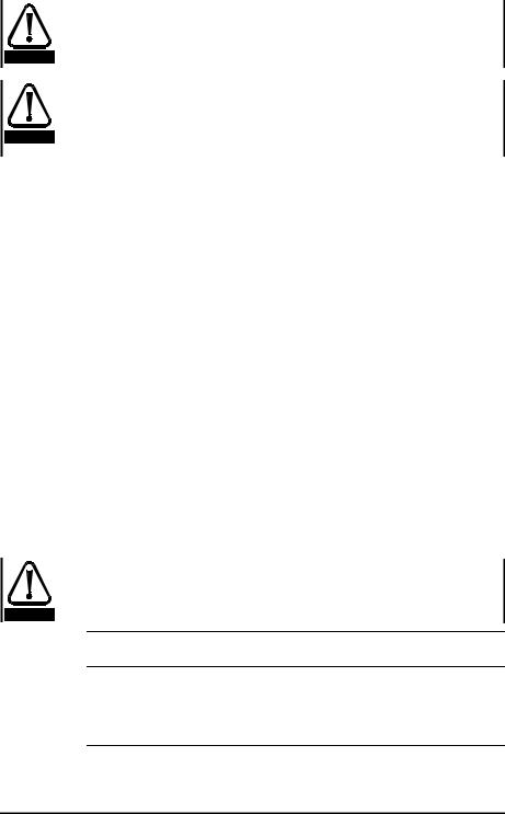
4.3Mechanical installation
4.3.1Drive and Mounting Dimensions
G
B A E
F |
F |
C
Commander SE Size 1 & 2 4 x M4 holes in heatsink
Commander SE Size 3 & 4 4 x M5 holes in heatsink
D
Figure 4.1 Drive and mounting dimensions
Drive |
|
A |
|
B |
|
C |
|
D |
|
E |
|
F |
G |
|
|||
Size |
|
|
|
|
|
|
|
|
|
|
|
|
|
|
|
|
|
|
|
|
|
|
|
|
|
|
|
|
|
|
|
|
|
|
|
|
mm |
in |
mm |
in |
mm |
in |
mm |
|
in |
mm |
in |
mm |
|
in |
mm |
in |
|
1 |
191 |
733/64 |
175 |
657/64 |
102 |
41/64 |
130 |
|
57/64 |
181.5 |
79/64 |
84 |
|
35/16 |
84 |
35/16 |
|
2 |
280 |
111/ |
259 |
103/ |
147 |
525/ |
130 |
|
57/ |
265 |
107/ |
121.5 |
|
425/ |
121.5 |
425/ |
32 |
|
|
64 |
|
16 |
|
32 |
|
|
64 |
|
16 |
|
|
32 |
|
|
|
3 |
336 |
137/32 |
315 |
1213/32 |
190 |
731/64 |
155 |
|
67/64 |
320 |
1219/32 |
172 |
|
625/32 |
164 |
629/64 |
|
4 |
412 |
167/32 |
389 |
155/16 |
250 |
927/32 |
185 |
|
79/32 |
397 |
155/8 |
228 |
|
863/64 |
217 |
835/64 |
|
NOTE
The Drive should be mounted vertically. A mounting template is provided on the Drive packing carton to aid installation.
Commander SE User Guide |
19 |
Issue Number 5 |

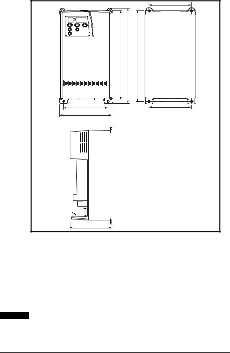
4.3.2Commander SE standard and low earth leakage Footprint/ Side mounting RFI Filter:
|
|
|
|
|
|
|
|
|
|
|
|
|
|
|
|
|
|
|
|
|
Size 1 and 2 |
|
|
|
|
|
|
|
|
|
|
|
|
||
|
|
8 x M4 holes |
|
|
|
|
||
|
Size 3 and 4 |
|
|
|||||
|
|
|
8 x M5 holes |
|
|
|
|
|
|
|
|
for footprint mounting |
|
|
|
|
|
|
|
|
|
|
|
|
|
|
|
|
|
|
|
|
|
|
|
|
|
|
|
|
|
|
|
|
|
|
|
|
|
|
|
|
|
|
|
|
|
|
|
|
|
|
|
|
|
|
|
|
|
|
|
|
|
|
|
|
|
|
Cable length |
|
|
|
||
|
|
|
|
|
|
|
|
|
|
|
|
|
|
|
|
|
|
|
|
|
|
|
|
|
|
|
||||
|
|
|
|
|
|
|
|
|
|
ÿ |
|
|
|
|
|
|
|
|
|
|
|
|
|
|
|
|
|
|
||
|
|
|
|
|
|
|
|
|
|
|
|
|
|
|
|
|
|
|
|
|
|
|
|
|
|
|
|
|||
|
|
|
|
|
|
|
|
|
|
|
|
|
|
|
|
|
|
|
|
|
|
|
|
|
|
|
|
|||
|
|
|
|
|
|
|
|
|
|
|
|
|
|
|
|
|
|
|
|
|
|
|
|
|
|
|||||
|
|
|
|
|
|
|
|
|
|
|
|
|
|
|
Figure 4.2 RFI filter dimensions |
|
|
|
||||||||||||
|
|
|
|
|
|
|
|
|
|
|
|
|
|
|
|
|
|
|
|
|
|
|
|
|
|
|
|
|||
Drive |
|
A |
|
|
|
B |
|
|
|
|
|
|
C |
|
D |
|
E |
|
|
F |
|
Cable |
||||||||
Size |
|
|
|
|
|
|
|
|
|
|
|
|
|
|
|
|
|
|
|
|
|
|
|
|
|
|
|
Length |
||
|
|
|
|
|
|
|
|
|
|
|
|
|
|
|
|
|
|
|
|
|
|
|||||||||
|
mm |
in |
|
mm |
|
|
in |
mm |
|
in |
mm |
|
|
in |
mm |
|
in |
mm |
in |
mm |
in |
|||||||||
|
|
|
|
|
|
|
|
|
|
|
|
|
|
|
|
|
|
|
||||||||||||
1 |
242 |
917/32 |
195 |
|
743/64 |
100 |
|
315/16 |
40 |
|
137/64 |
225 |
|
87/8 |
80 |
35/32 |
190 |
731/64 |
||||||||||||
2 |
330 |
13 |
|
281 |
|
111/ |
16 |
148 |
|
513/ |
45 |
|
149/ |
313 |
|
1221/ |
122 |
451/ |
250 |
927/ |
||||||||||
|
|
|
|
|
|
|
|
|
|
|
|
|
|
16 |
|
|
64 |
|
|
64 |
|
|
64 |
|
|
32 |
||||
3 |
385 |
155/ |
32 |
336 |
|
1315/ |
|
190 |
|
731/ |
50 |
|
131/ |
368 |
|
1431/ |
164 |
629/ |
270 |
105/ |
||||||||||
|
|
|
|
|
|
|
64 |
|
|
|
|
|
64 |
|
|
32 |
|
|
64 |
|
|
64 |
|
|
8 |
|||||
4 |
467 |
1825/ |
64 |
414 |
|
1619/ |
|
246 |
|
911/ |
55 |
|
211/ |
448 |
|
1741/ |
215 |
815/ |
320 |
1219/ |
||||||||||
|
|
|
|
|
|
|
|
64 |
|
|
|
|
|
16 |
|
|
64 |
|
|
64 |
|
|
32 |
|
|
32 |
||||
20 |
Commander SE User Guide |
Issue Number 5 |
|
|
|

4.3.3Commander SE Size 1 Low Cost RFI Filter mounting dimensions, 4200-6101.
Figure 4.3 Size 1 Low cost filter dimensions
|
A |
|
B |
C |
|
|
D |
||||
|
|
|
|
|
|
|
|
|
|
|
|
mm |
|
in |
mm |
|
in |
mm |
|
in |
mm |
|
in |
|
|
|
|
|
|
|
|
|
|
|
|
113.5 |
|
415/32 |
103 |
|
41/16 |
58 |
|
29/32 |
45.5 |
|
151/64 |
4.3.4Commander SE Size 2 and 3 Low cost single and three phase RFI Filter mounting dimensions, 4200-6204 and 4200-6304.
Cable length 4200-6204 = 250mm 4200-6304 = 300mm
Figure 4.4 RFI filter dimensions
|
A |
|
|
B |
|
|
C |
|
|
D |
|
|
E |
|
F |
|
G |
|||||||
mm |
|
in |
mm |
|
in |
mm |
|
in |
|
mm |
|
in |
|
mm |
|
in |
mm |
|
in |
mm |
|
in |
||
119 |
|
411/ |
16 |
98.5 |
|
37/ |
8 |
85.5 |
|
321/ |
64 |
57.6 |
|
217/ |
64 |
109 |
|
419/ |
51 |
|
2 |
66 |
|
219/ |
|
|
|
|
|
|
|
|
|
|
|
|
|
|
64 |
|
|
|
|
|
32 |
||||
Commander SE User Guide |
21 |
Issue Number 5 |
 Loading...