


Condec UPS3210 User Manual
UPS3000, UPS3110 &
UPS3210
Portable & Rack-mountable Pneumatic Pressure Standards
Operation & Maintenance
Manual
CONDEC Sales Phone No.: (888) 295-8475
CONDEC Web Site: WWW.4CONDEC.COM
63253

2 UPS3000/UPS3110/UPS3210 Operation and Maintenance Manual

Contents
1.0 Introduction.................................................................................................................................. 2
2.0 Operation...................................................................................................................................... 4
2.1 Unpacking and Inspection . . . . . . . . . . . . . . . . . . . . . . . . . . . . . . . . . . . . . . . . . . . . . . . . . . . . . . . . . 4
2.2 Standard Display/Keyboard Front Panel Functions . . . . . . . . . . . . . . . . . . . . . . . . . . . . . . . . . . . . . . . 4
2.3 Rear Panel Configuration . . . . . . . . . . . . . . . . . . . . . . . . . . . . . . . . . . . . . . . . . . . . . . . . . . . . . . . . . . 6
2.4 Configuration Switch Settings. . . . . . . . . . . . . . . . . . . . . . . . . . . . . . . . . . . . . . . . . . . . . . . . . . . . . . . 8
2.4.1 APC4000/APC4001 Interface Option Enable. . . . . . . . . . . . . . . . . . . . . . . . . . . . . . . . . . . . . . . . . . . . . 9
2.4.2 Peak Hold or MAX/MIN Option Enable . . . . . . . . . . . . . . . . . . . . . . . . . . . . . . . . . . . . . . . . . . . . . . . . . 9
2.4.3 Conversion Enable . . . . . . . . . . . . . . . . . . . . . . . . . . . . . . . . . . . . . . . . . . . . . . . . . . . . . . . . . . . . . . . 10
2.4.4 Digital Averaging . . . . . . . . . . . . . . . . . . . . . . . . . . . . . . . . . . . . . . . . . . . . . . . . . . . . . . . . . . . . . . . . . 10
2.4.5 AUTO-ZERO Maintenance (AZM) Enable. . . . . . . . . . . . . . . . . . . . . . . . . . . . . . . . . . . . . . . . . . . . . . . 10
2.4.6 Automatic Span Maintenance (ASM) Enable . . . . . . . . . . . . . . . . . . . . . . . . . . . . . . . . . . . . . . . . . . . . 10
2.5 Freeze Mode Option Wiring . . . . . . . . . . . . . . . . . . . . . . . . . . . . . . . . . . . . . . . . . . . . . . . . . . . . . . . 11
2.6 Engineering Conversion with PEAK HOLD or MAX/MIN Option. . . . . . . . . . . . . . . . . . . . . . . . . . . . . 12
2.7 UPS3000 or UPS3210 Initial Setup Sequence . . . . . . . . . . . . . . . . . . . . . . . . . . . . . . . . . . . . . . . . . 13
2.7.1 UPS3000 or UPS3210 Display of Pressure Sequence GAGE Mode . . . . . . . . . . . . . . . . . . . . . . . . . . 13
2.7.2 UPS3000 or UPS3210 Display of Pressure Sequence Absolute (ABS) Mode. . . . . . . . . . . . . . . . . . . . 13
2.8 UPS3110 Initial Setup Sequence . . . . . . . . . . . . . . . . . . . . . . . . . . . . . . . . . . . . . . . . . . . . . . . . . . . 14
2.8.1 UPS3110 Pressure Measurement Sequence GAGE Mode . . . . . . . . . . . . . . . . . . . . . . . . . . . . . . . . . 14
2.8.2 UPS3110 Pressure Measurement Sequence Absolute (ABS) Mode. . . . . . . . . . . . . . . . . . . . . . . . . . . 15
2.9 GAGE Mode Self-Check. . . . . . . . . . . . . . . . . . . . . . . . . . . . . . . . . . . . . . . . . . . . . . . . . . . . . . . . . . 15
2.10 Battery Operation . . . . . . . . . . . . . . . . . . . . . . . . . . . . . . . . . . . . . . . . . . . . . . . . . . . . . . . . . . . . . . 16
2.11 Serial Output: 20 mA Loop . . . . . . . . . . . . . . . . . . . . . . . . . . . . . . . . . . . . . . . . . . . . . . . . . . . . . . . 16
2.11.1 Hardware Configuration . . . . . . . . . . . . . . . . . . . . . . . . . . . . . . . . . . . . . . . . . . . . . . . . . . . . . . . . . . . 16
2.11.2 Serial Output Software Configuration. . . . . . . . . . . . . . . . . . . . . . . . . . . . . . . . . . . . . . . . . . . . . . . . . . 16
2.11.3 DATA FORMAT TABLE . . . . . . . . . . . . . . . . . . . . . . . . . . . . . . . . . . . . . . . . . . . . . . . . . . . . . . . . . . . . 17
2.11.4 SERIAL OUTPUT CONFIGURATION TABLE . . . . . . . . . . . . . . . . . . . . . . . . . . . . . . . . . . . . . . . . . . . . 18
3.0 Calibration and Adjustment Procedure ..................................................................................... 19
3.1 Pneumatic Calibration Set-Up . . . . . . . . . . . . . . . . . . . . . . . . . . . . . . . . . . . . . . . . . . . . . . . . . . . . . 19
3.2 Instrument Calibration Set-Up . . . . . . . . . . . . . . . . . . . . . . . . . . . . . . . . . . . . . . . . . . . . . . . . . . . . . 20
3.3 Zero/Span Calibration. . . . . . . . . . . . . . . . . . . . . . . . . . . . . . . . . . . . . . . . . . . . . . . . . . . . . . . . . . . . 21
3.4 Linearity and Hysteresis Calibration . . . . . . . . . . . . . . . . . . . . . . . . . . . . . . . . . . . . . . . . . . . . . . . . . 21
3.5 Shunt Resistor Calibration . . . . . . . . . . . . . . . . . . . . . . . . . . . . . . . . . . . . . . . . . . . . . . . . . . . . . . . . 23
3.6 Permanent Data Storage . . . . . . . . . . . . . . . . . . . . . . . . . . . . . . . . . . . . . . . . . . . . . . . . . . . . . . . . . 23
3.7 Barometric Offset - Absolute/Gage Switch Selectable Units ONLY. . . . . . . . . . . . . . . . . . . . . . . . . . 23
3.7.1 For UPS3000/UPS3210 Absolute/Gage Switch Selectable Units ONLY . . . . . . . . . . . . . . . . . . . . . . . 24
3.7.2 For UPS3110 Absolute/Gage Switch Selectable Units ONLY . . . . . . . . . . . . . . . . . . . . . . . . . . . . . . . 26
4.0 Maintenance & Service ............................................................................................................. 28
4.1 Troubleshooting . . . . . . . . . . . . . . . . . . . . . . . . . . . . . . . . . . . . . . . . . . . . . . . . . . . . . . . . . . . . . . . . 28
4.2 Maintenance & Service Procedures . . . . . . . . . . . . . . . . . . . . . . . . . . . . . . . . . . . . . . . . . . . . . . . . . 28
4.2.1 Case Removal and Installation. . . . . . . . . . . . . . . . . . . . . . . . . . . . . . . . . . . . . . . . . . . . . . . . . . . . . . . 28
4.2.2 ORION-2C (PN 55283) or ORION-3A (PN 55287) Manifold Removal . . . . . . . . . . . . . . . . . . . . . . . . . . 29
4.2.3 ORION Manifold - Valve Seat Removal . . . . . . . . . . . . . . . . . . . . . . . . . . . . . . . . . . . . . . . . . . . . . . . . 30
4.2.4 ORION Manifold - Vernier Control Disassembly . . . . . . . . . . . . . . . . . . . . . . . . . . . . . . . . . . . . . . . . . . 31
4.2.5 ORION Manifold - Vernier Control Reassembly . . . . . . . . . . . . . . . . . . . . . . . . . . . . . . . . . . . . . . . . . . 31
4.2.6 ORION Manifold - Valve Seat Installation . . . . . . . . . . . . . . . . . . . . . . . . . . . . . . . . . . . . . . . . . . . . . . . 32
4.2.7 ORION - Manifold, Panel Installation . . . . . . . . . . . . . . . . . . . . . . . . . . . . . . . . . . . . . . . . . . . . . . . . . . 33
4.2.8 ORION 2C Manifold - Valve Adjustment Procedure . . . . . . . . . . . . . . . . . . . . . . . . . . . . . . . . . . . . . . . 34
4.2.9 ORION 3A Manifold - Valve Adjustment Procedure. . . . . . . . . . . . . . . . . . . . . . . . . . . . . . . . . . . . . . . 35
4.2.10 Pressure Limit Control (Standard Pneumatic), Regulator Removal . . . . . . . . . . . . . . . . . . . . . . . . . . . . 36
4.2.11 Pressure Limit Control (Standard Pneumatic), Regulator Installation . . . . . . . . . . . . . . . . . . . . . . . . . . 36
i

4.2.12 Pressure Limit Control (Tescom), Regulator Removal . . . . . . . . . . . . . . . . . . . . . . . . . . . . . . . . . . . . . 37
4.2.13 Pressure Limit Control (Tescom), Regulator Installation. . . . . . . . . . . . . . . . . . . . . . . . . . . . . . . . . . . . 37
4.2.14 Panel Gauge Removal . . . . . . . . . . . . . . . . . . . . . . . . . . . . . . . . . . . . . . . . . . . . . . . . . . . . . . . . . . . . 38
4.2.15 Panel Gauge Installation . . . . . . . . . . . . . . . . . . . . . . . . . . . . . . . . . . . . . . . . . . . . . . . . . . . . . . . . . . . 38
4.2.16 Test Port Quick-Connect Fitting (PN 59762) Removal and Installation - 15, 50 and 100 Full Scale PSI 39
4.2.17 Test Port Quick-Connect Fitting (PN 55426), Removal and Installation - 500, 1000 and 2000 Full Scale PSI
. . . . . . . . . . . . . . . . . . . . . . . . . . . . . . . . . . . . . . . . . . . . . . . . . . . . . . . . . . . . . . . . . . . . . . . . . . . . . . 39
4.2.18 Test Port Filter (PN 54188), Removal and Installation - 500, 1000 and 2000 Full Scale PSI . . . . . . . . . 40
4.2.19 Test Port Filter (PN 54188), Removal and Installation - 15, 50 and 100 Full Scale PSI . . . . . . . . . . . . . 40
4.2.20 Test Port Quick-Connect Fitting (PN 59004) and Filter (PN 54188) Removal and Installation - 5000 and
10000 Full Scale PSI . . . . . . . . . . . . . . . . . . . . . . . . . . . . . . . . . . . . . . . . . . . . . . . . . . . . . . . . . . . . . . 41
4.2.21 AC Fuse (PN 58076), Removal and Installation . . . . . . . . . . . . . . . . . . . . . . . . . . . . . . . . . . . . . . . . . . 41
4.2.22 AC Power/EMI Line Filter (PN 58870), Removal and Installation . . . . . . . . . . . . . . . . . . . . . . . . . . . . . 42
4.2.23 Power Switch Cable (PN 55351), Removal and Installation (Battery Units). . . . . . . . . . . . . . . . . . . . . . 42
4.2.24 Power Switch (PN 58878), Removal and Installation . . . . . . . . . . . . . . . . . . . . . . . . . . . . . . . . . . . . . . 42
4.2.25 Range Select Switch Cable (PN 56014), Removal and Installation. . . . . . . . . . . . . . . . . . . . . . . . . . . . 43
4.2.26 Power Supply Assembly, Removal and Installation (Battery Units). . . . . . . . . . . . . . . . . . . . . . . . . . . . 43
4.2.27 BATTERY (55851), Removal, Installation and Adjustments . . . . . . . . . . . . . . . . . . . . . . . . . . . . . . . . . 44
4.3 ORION 2C Valve Assembly Parts List . . . . . . . . . . . . . . . . . . . . . . . . . . . . . . . . . . . . . . . . . . . . . . . 45
4.4 ORION 3A Valve Assembly Parts List. . . . . . . . . . . . . . . . . . . . . . . . . . . . . . . . . . . . . . . . . . . . . . . . 47
4.5 UPS3000 Assembly Drawings . . . . . . . . . . . . . . . . . . . . . . . . . . . . . . . . . . . . . . . . . . . . . . . . . . . . . . 49
5.0 Model Number System .............................................................................................................. 50
6.0 Available Ranges, Multi-Conversions and Resolutions ............................................................ 51
7.0 Options, Replacement Kits ........................................................................................................ 54
7.1 Freeze Mode Option - PN 57778 . . . . . . . . . . . . . . . . . . . . . . . . . . . . . . . . . . . . . . . . . . . . . . . . . . . 54
7.2 Peak Hold Option . . . . . . . . . . . . . . . . . . . . . . . . . . . . . . . . . . . . . . . . . . . . . . . . . . . . . . . . . . . . . . 54
7.3 Min and Max Mode Option . . . . . . . . . . . . . . . . . . . . . . . . . . . . . . . . . . . . . . . . . . . . . . . . . . . . . . . 55
7.4 Analog Output Option (0 VDC to +10 VDC) . . . . . . . . . . . . . . . . . . . . . . . . . . . . . . . . . . . . . . . . . . . 56
7.5 Analog Output Option (+4 mA DC to +20 mA DC) . . . . . . . . . . . . . . . . . . . . . . . . . . . . . . . . . . . . . . 56
7.6 RS232 Simplex Output Option Mode. . . . . . . . . . . . . . . . . . . . . . . . . . . . . . . . . . . . . . . . . . . . . . . . 57
7.7 Replacement Kits . . . . . . . . . . . . . . . . . . . . . . . . . . . . . . . . . . . . . . . . . . . . . . . . . . . . . . . . . . . . . . 57
8.0 Specifications............................................................................................................................ 59
ii UPS3000/UPS3110/UPS3210 Operation & Maintenance Manual

About This Manual
The bench-top UPS3000 and the rack-mountable UPS3110 and UPS3210 pneumatic pressure standards are
rugged, compact instruments manufact ure d by COND EC. Th ey are designed to provide superior accuracy, range
of calibration and ease of operation when used to assist in the manufacture, test and/or calibration of a wide
variety of pressure sensing and measuring devices.
These instruments utilize an extremely repeatable sensor coupled to microprocessor-based electronic circuitry
and a selectable units display system. This provides easily readable and accurate digital representation of the
measured pressure. If required for portable use, the optional battery models, are able to provide up to six hours of
use.
The UPS3110 all electro-mechanical device has our precision Orion vernier and one test port. Some models
contain a front panel gage, to show the operator the input pressure, as well as, a pressure regulator that will act as
a pressure limiter so that the operator can not over pressure a unit under test. A test hose is supplied for the
customer. Standa rd fro nt pane l buttons and switches provide selection of the desired pressure range, push-button
zeroing and the unique internal self-check feature.
This manual has been written to give the user a simple and clear explanation of how to operate, calibrate and
maintain these instruments.
Before attempting to use either style, Pressure Standard, the following instructions
#AUTION
must be carefully read and understood by personnel utilizing the equipment. This is a
high-pressure system. While a substantial effort has been expended to make this
equipment safe, simple and fool-proof to operate, it is strongly recommended that only
personnel formally trained in the use of pneumatic pressure equipment be permitted to
operate it. Potentially dangerous conditions could be produced through negligent
handling or operation of the console due to the high pressure contained within the unit.
UPS3110 units are strictly for use with pneumatic pressures. Erroneous readings and
potential damage could result from the introduction of hydraulic fluids into the internal
tubing lines.
Authorized distributors and their
employees can view or download this
manual from the Condec distributor
www.4condec.com.
site at
1

1.0 Introduction
Utilizing microprocessor technology, the UPS3000, rack-mountable UPS3110 and UPS3210 instruments offer a
combination of features, performance, versatility and reliability not previously available in a single,
self-contained pressure calibration instrument. The following list notes the features and benefits of each unit:
• Three independent switch-selectable pressure ranges per instrument.
• Nine button-selectable units (PSI, kPa, Bar, mBar, kg/cm2, mmHg, inHg, cmH2O, inH2O) plus percent
of full scale may be displayed on instrument.
• Accuracy of each range equal to or better than ±0.05% Full Scale.
• Both “Gage” and “Absolute” pressure calibrations available via front panel switch selection.
• Automatic self-check: Computer-controlled internal circuitry provides automatic maintenance of both
zero and span calibration data to insure long-term stability and accuracy.
• Digital Display: Eliminates parallax, interpolation and operator judgement errors. Large, bright, red LED
digits provide excellent readability under all lighting conditions.
• UPS3110 only - Using a manually adjustable regulator, the maximum system input pressure is adjusted
to any desired value higher (typically 20 to 50%) than the full scale range of the device being tested. By
virtue of this technique, the unit under test is fully protected from being inadvertently over-pressurized.
• Fast Response: Pressure data refreshed and updated at the rate of 12 time s per second.
• Data Output: Serial Data, 20 mA loop, ASCII code format with start, stop and parity bits supplied as
standard practice. RS232 Simplex output available as an option.
• Calibration Integrity: Tamper-proof design. Once calibrated, numerous safeguards guarantee the
integrity of pressure readings obtained. Display prompting provides the operator with functional status
information during both operation and calibration.
• P ressure Media: UPS3000 and UPS3210, any gas or fluid compatible with 17-4 PH stainles s steel alloy.
UPS3110, only gas compatible with 17-4 PH stainless steel alloy.
• Simple Operation: All controls and indicators are accessible from the front panel. Accompanying
operator's manual provides clear, concise instructions for system operation
• S afe, Clean Operation: All pressure components are made of brass, copper, aluminum or stainless steel
and proof-tested to at least 150% of maximum operating pressure. In addition, the UPS3110 system
contains a high-pressure relief valve to protect both the operator and system components from harm in
the event of inadvertent over-pressurization.
The heart of this indicator/calibration system is a highly stable and repeatable pressure transducer. These sensors
produce an electrical output signal which is linearly proportional to the applied pressure. This transduction
technique has been employed by CONDEC for many years and has realized hundreds of thousands of hours of
reliable operation.
By combining these sensors with sophisticated microprocessor-based circuitry, an even higher degree of
operational accuracy and precision has been accomplished. For example, computer-generated correction curves
for both the non-linearity and the hysteresis of the sensors improve these characteristics by an order of magnitude
or more. In addition, a “self-calibration” feature insures long-term accuracy by utilizing the computer to generate
and control an internal “shunt calibration mode” of operation. The indicators full-scale reading is compared
against, and if necessary, corrected to the digitally-stored value for full scale obtained at the time of initial
pressure calibration.
The UPS3000 and UPS3210 indicators, as well as, the UPS3110 calibrator has capability for an internal,
rechargeable 12 volt lead acid battery, which provides a minimum of 6 hours of complete usage, when battery is
fully charged. An ON/OFF switch is provided to conserve energy when the instrument is not in use. It also has a
LO BATT indicator. After receiving and prior to operating new battery models, reinstall (+) cable, red wire, on
battery.
2 UPS3000/UPS3110/UPS3210 Operation & Maintenance Manual
With all its sophistication however, a great deal of effort has been expended to make the instruments simple to
operate and easy to calibrate.
Two micro-metering valves and vernier are provided to control the UPS3110 pressure source while the digital
display indicates precisely the magnitude of the applied test pressure. Also, a pair of simple push-button switches
provide both “zeroing” of the pressure display and the selection of either the “Gage” or “Absolute” calibration
mode. In like manner, the “Range” selection is accomplished via a clearly marked rotary switch. Over-pressure
protection is provided on lower pressure UPS3110 models via a fully adjustable pressure regulator which is
manually set for each new device being tested.
With respect to calibration, the instruments have been designed and programmed to be very user friendly in that
they provide the operator with various prompting symbols and legends during each phase of the calibration
sequence. Also, to prevent unauthorized tampering or calibrations, numerous features have been incorporated
which greatly minimize this potential danger. Also, the electronic circuitry ha s been designed without any
potentiometers or adjustments which eliminates the possibility of unwanted changes. Finally, the computer has
been programmed with a series of internal self-diagnostic routines which continually monitor and check every bit
of data stored and processed by this system, and immediately either notes or shuts down operation in the event of
an out-of-tolerance reading or outright failures.
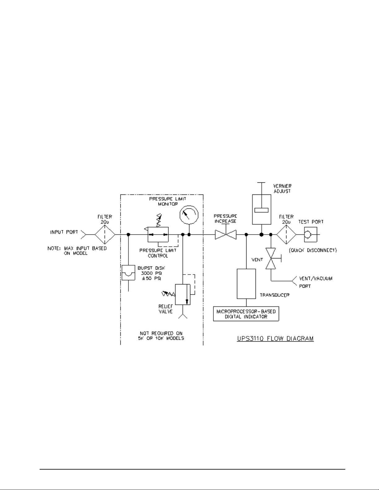
The following schematic provides an overview of the UPS3110’s function.
Figure 1-1. UPS3110 Flow Diagram
Introduction 3

2.0 Operation
2.1 Unpacking and Inspection
When received, carefully remove the instrument from its shipping container. A visual inspection of the
instrument’s external surfaces should be performed immediately after unpacking. If obvious damage has been
incurred during transit, the shipping agency and the distributor should be notified as soon as possible.
Instructions as to how to proceed after assessment of the damage will then be determined. If the instrument
shows no signs of damage, c heck to be sure all the required equipment and accessories have been received. See
“Options, Replacement Kits” on page 54, for all options.
NOTE: Prior to operating battery models, reinstall (+) cable, red wire, on battery.
2.2 Standard Display/Keyboard Front Panel Functions
UPS3000 See Figure 2-1 on page 5, UPS3110 See Figure 2-2 on page 5, UPS3210 See Figure 2-3 on page 6.
1. Six Digit LED display of the measured pressure. This display also prompts if a problem occurred in
performing an operation.
2. Three Annuciators (4). Two of the LEDs are used for indicating whether the instrument is operating as a
Gage pressure instrument or as an absolute (ABS) pressure instrument. The third LED indicates the
conversion units that the pressure data is currently being displayed in.
3. ZERO function key (1). In GAGE mode and ABS only instruments this key allows the indicator to be
zeroed.
NOTE: If attempting to perform a push to ZERO while the pressure data is in motion, the instrument will not go to ZERO.
NOTE: The four, or five if options have been installed, push button switches located across the lower face of the front
panel are individually actuated by momentarily pressing with a light fingertip motion anywhere within the black outlines
of the button. When actuated, each switch produces a visual feedback through the digital display.
4. ABS/GAGE function key (2), toggles instrument to be a Gage pressure instrument or an absolute (ABS)
pressure instrument.
NOTE: This key is blank and non-functional if unit is an Absolute (Abs) only pressure unit or a Gage only pressure unit.
5. CONV conversion key (3), is used to select the conversion units that the pressure data is currently being
displayed in.
6. CAL function key (5), activates the internal Self-Check feature. See “GAGE Mode Self-Check” on
page 15.
NOTE: CAL key is non-functional in absolute mode.
7. RANGE SELECT switch (6), used to select the desired pressure range.
NOTE: Do not turn switch between ranges during a cycle.
8. UPS3110 instrument with maximum range of 2K PSI or less: PRESSURE LIMIT CONTROL (7), for
regulating the input pressure to the unit.
9. UPS3110 instrument with maximum range of 2K PSI or less: PRESSURE LIMIT MONITOR (8), indicates
input pressure going to the unit.
10. UPS3110 instrument: TEST PORT (9), for connecting to the Device-Under-Test (DUT).
11. UPS3110 instrument: INPUT Valve (10), used for nearing target pressure of the DUT.
12. UPS3110 instrument: VERNIER Valve (11), used for precisely setting target pressure of the DUT.
13. UPS3110 instrument: VENT Valve (12), used for venting pressure of the DUT.
4 UPS3000/UPS3110/UPS3210 Operation & Maintenance Manual
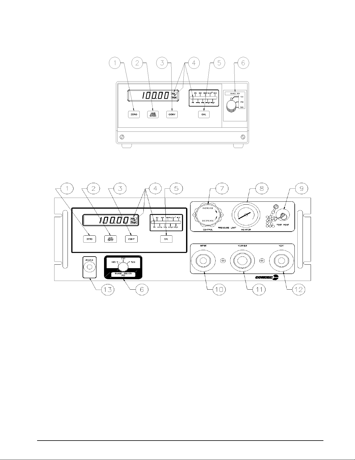
Figure 2-1. UPS3000 Desktop/Panel-mountable Pressure Indicator Display/Keyboard Functions
Figure 2-2. UPS3110 Rack-mountable Front Pressure Calib rator Panel Function s
Operation 5
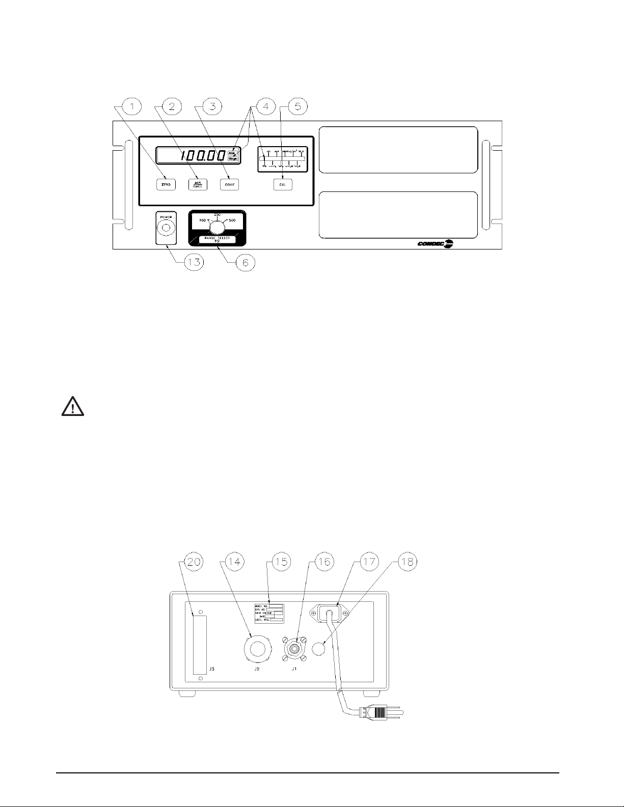
Figure 2-3. UPS3210 Rack-mountable Pressure Indica tor Front Panel Functions
2.3 Rear Panel Configuration
UPS3000 Series, See Figure 2-4 below, contains the following:
1. AC power cord, and input receptacle (17).
2. INPUT PRESSURE port J1 (16), 7/16-20, 37o-4 AN male fitting.
Application of pressures greater than 1.5 times the highest pressure range of the indicator may cause
#AUTION
3. The unit’s identification plate (15).
4. Optional if required items:
• Connector J2 (14), 5 pin round MS style connector, for Serial or Analog Output communication board.
• Connector J3 (20), 15 pin D connector, for the PCM1000 Controller Interface.
• Connector (18), 5 pin round connector, for the Freeze Mode Cable.
NOTE: For further information, see “Options, Replacement Kits” on page 54.
calibration errors or even permanent damage to the pressure transducer.
Figure 2-4. UPS3000 Desktop/Panel-mountable Pressure Indicator Rear View
6 UPS3000/UPS3110/UPS3210 Operation & Maintenance Manual
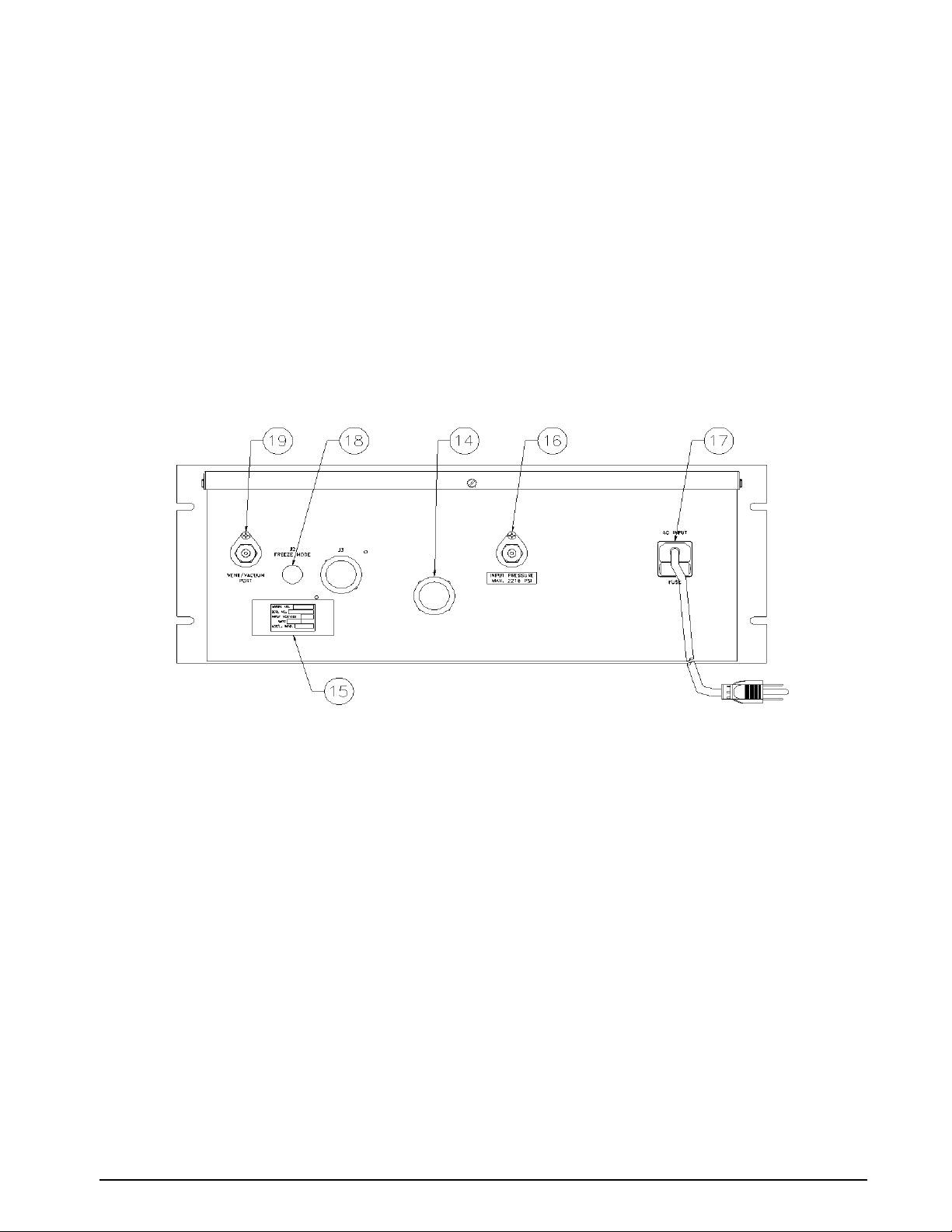
UPS3110 Rack-mountable Series, See Figure 2-5 below, contains the following:
1. AC power cord, fuse holder and input receptacle (17).
2. INPUT PRESSURE port (16), 7/16-20, 37o-4 AN male fitting. Location of port for AC only units.
NOTE: The maximum input pressure, supplied by user, is noted below port.
3. The unit’s identification plate (15).
4. VENT/VACUUM PORT (19), 7/16-20, 37o-4 AN male fitting.
5. Optional if required items:
Connector J1 (14), 5 pin round MS style connector, for Serial or Analog Output communication board or
location of Input Pressure port for models with battery.
Connector J2 (18), 5 pin round connector, for the Freeze Mode Cable.
NOTE: For further information, see “Options, Replacement Kits” on page 54.
Figure 2-5. UPS3110 Rack-mountable Pressure Calibrator Rear View
UPS3210 Rack-mountable Series, See Figure 2-6 on page 8, contains the following:
1. AC power cord, fuse holder and input receptacle (17).
2. INPUT PRESSURE port J3 (16), 7/16-20, 37o-4 AN male fitting.
NOTE: The maximum input pressure, supplied by user, is noted above port.
3. The unit’s identification plate (15).
4. Optional if required items:
Connector J1 (14), 5 pin round MS style connector, for Serial or Analog Output communication board.
Connector J2 (18), 5 pin round connector, for the Freeze Mode Cable.
Con n ector J4, lo c ated b elow i d entif icati o n plat e, req u ired f or APC 4 000/A PC400 1 inter f ace ca ble.
NOTE: For further information, see “Options, Replacement Kits” on page 54.
Operation 7
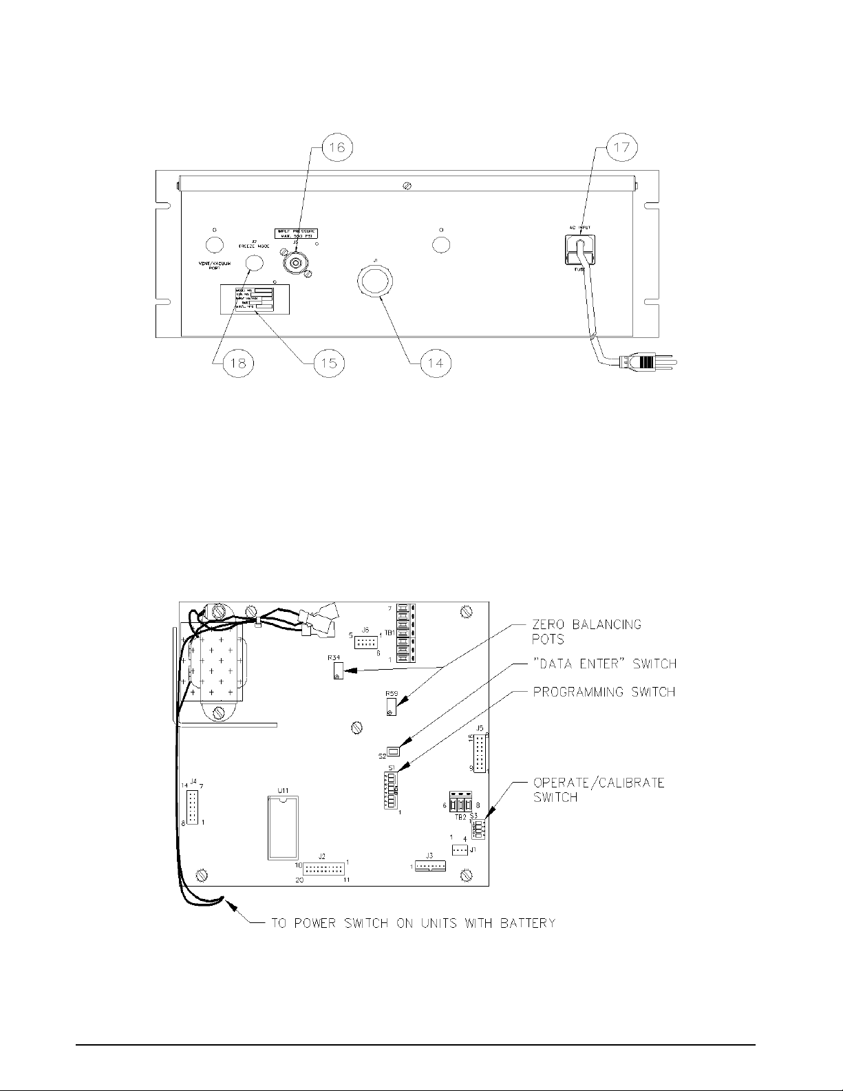
Figure 2-6. UPS3210 Rack-mountable Pressure Indicator Rear View
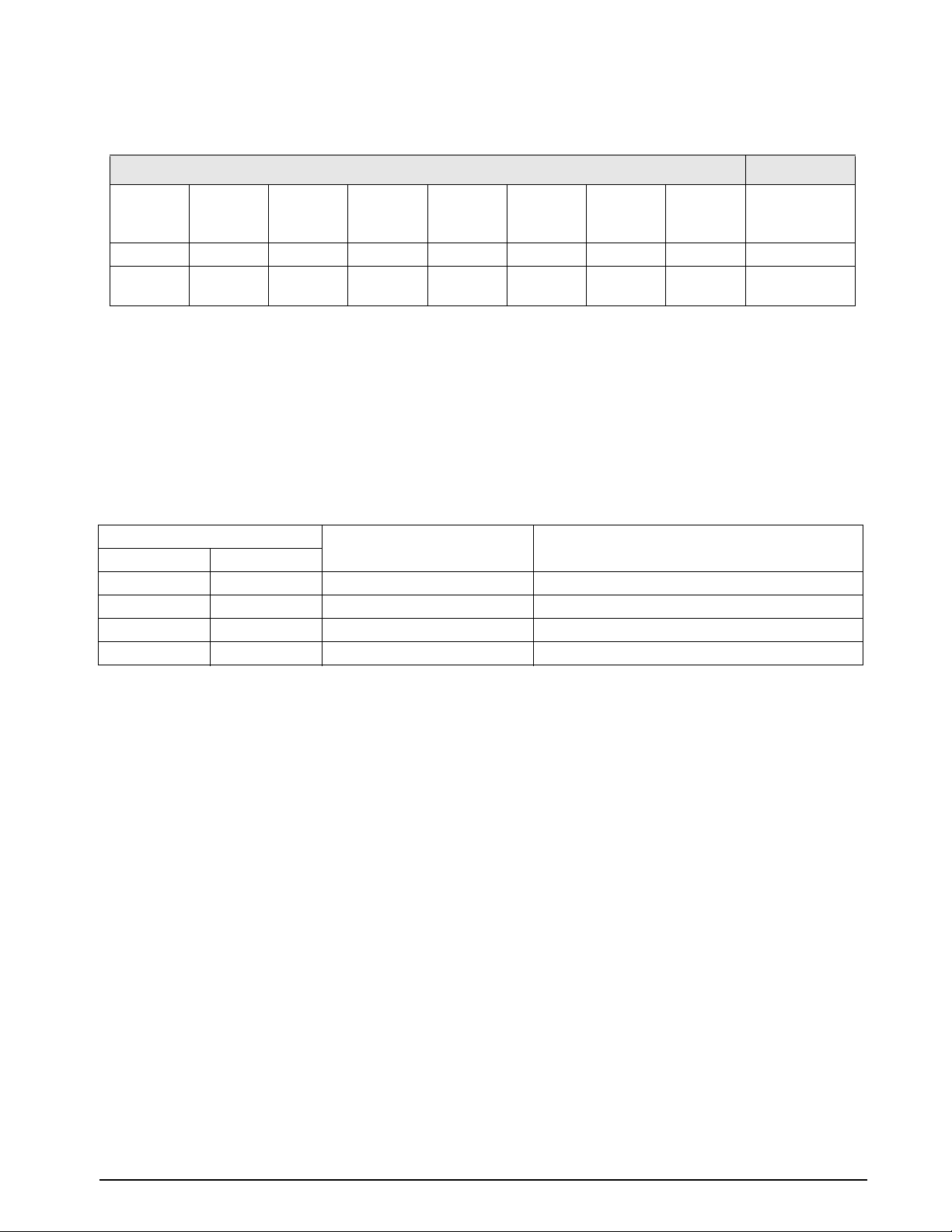
2.4 Configuration Switch Settings
As normally supplied, the UPS3000, UPS3110 and UPS3210 will be fully calibrated and configured to the
requirements specified by the customer purchase order. However, there are several functions or operational
features that may be selected or altered by the operator during usage. These are controlled by the eight-position
DIP switch, S1, located on the CPU board as shown in Figure 2-7.
NOTE: To gain access to the CPU board see “Case Removal and Installation” on page 28.
Figure 2-7. CPU Configuration Switch Locations
8 UPS3000/UPS3110/UPS3210 Operation & Maintenance Manual
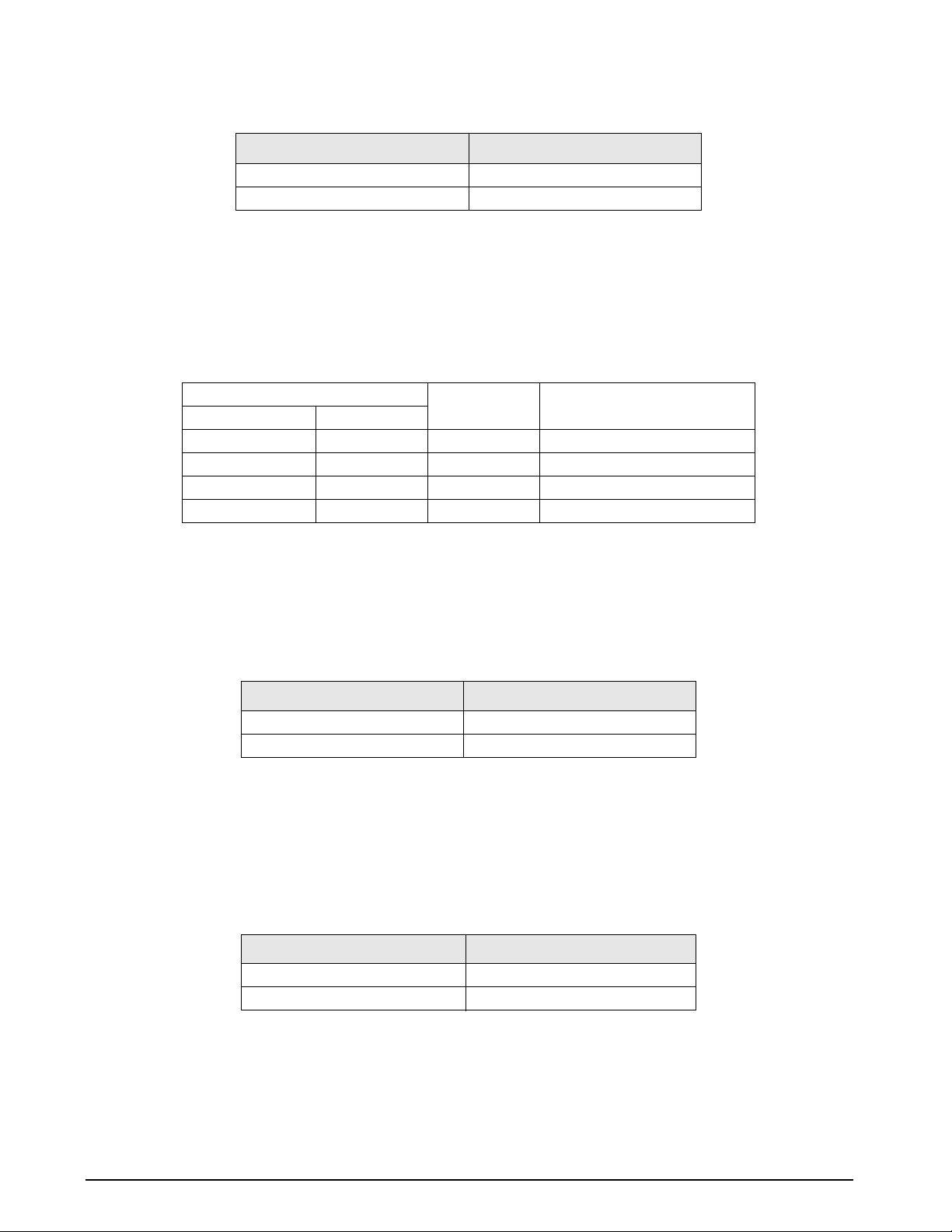
2.4.1 APC4000/APC4001 Interface Option Enable
Switch Settings S1
Position 1 Position 2 Position 3 Position 4 Position 5 Position 6 Position 7 Position 8 UPS 3000
UPS 3110
UPS 3210
0 0 1 0 0 0 1 1 With Controller
0 0 1 0 0 0 1 0 Without
Controller
Table 2-1. APC 4000/APC 4001 Interface Enable Switch Settings
The APC4000 interface enable is activated only for models that are purchased and used with the PCM1000-1
controller or part of an APC4001 controller system. When UPS3000 or UPS3210 is used in conjunction with a
controller, Peak Hold, Freeze Mode or MIN/MAX Mode options are not available.
NOTE: UPS3110 is not used with a controller.
Approximately 1994 multi conversion software was added to UPS3000 models, therefore UPS3000 and PCM1000 units
made prior to this will not work with the ones manufactured after that date. Consult factory for information on upgrading
units.
2.4.2 Peak Hold or MAX/MIN Option Enable
See “Peak Hold Option” on page 54 or “Min and Max Mode Option” on page 55.
Switch Settings S1 Peak Hold or MAX/MIN Mode *ABS/GAGE Mode
Position 1 Position 2
0 0 Disabled ABS & Gauge (Front Panel Switch Selectable)
0 1 Disabled Gauge or ABS only
1 0 Enabled ABS & Gauge (Front Panel Switch Selectable)
1 0 Enabled Gauge or ABS only
Table 2-2. Peak Hold or MAX/MIN Enable Switch Settings
NOTE: * Absolute or Gage modes of operation are factory set, depending upon the style of transducer supplied and the
type of internal memory configuration utilized.
When the Absolute/Gage switching is not utilized; the front panel ABS/GAGE push-button switch will be
programmed to inactive and covered with a blank overlay.
When the PEAK HOLD Option or MAX/MIN option is supplied switching from Absolute to Gauge mode via
the front panel is possible and the Freeze Mode option, if supplied, is operable.
NOTE: When the PEAK HOLD or MAX/MIN option is supplied, the CONV button is no longer active or present on front
panel. Therefore, the required conversion must be set thru reconfiguration. See
HOLD or MAX/MIN Option” on page 12 for applicable method to change to required conversion.
“Engineering Conversion with PEAK
Operation 9
2.4.3 Conversion Enable
Switch Setting S1 Position 3 Front Panel Conv Key Mode
0 Disabled
1 Enabled
Table 2-3. Conversion Enable Switch Setting
As standard practice, the instruments are supplied with display indication in PSI (either Absolute, Gage or both)
and capable of being converted to a range of nine units via the front panel
NOTE: When the PEAK HOLD or MAX/MIN option is supplied with a model having the ABS or GAGE mode, switch
selectable from front panel, the “CONV” button will be disabled and will not be present on the front panel. Therefore, the
required conversion must be set thru reconfiguration. See “Engineering Conversion with PEAK HOLD or MAX/MIN
Option” on page 12 for applicable method to change to required conversion.
2.4.4 Digital Averaging
Switch Setting S1 Average Select Approximate Update Rate
Position 4 Position 5
0 0 1 (Off) 12/sec.
1 0 2 6/sec.
0 1 4 3/sec.
1 1 Auto 3-12/sec.
Table 2-4. Digital Averaging Switch Setting
CONV push-button switch.
Digital Averaging is a technique whereby numerous update cycles are averaged together before the numerical
display data is changed. In essence, this feature acts as a variable rate electronic filter to provide a more stable
pressure indication reading.The “
AUTO” mode of this filter allows the display to update rapidly (12/sec.) when
the input pressure is being quickly changed and yet provides extremely stable display operation (3/sec.) when the
desired pressure input value has been obtained.
2.4.5 AUTO-ZERO Maintenance (AZM) Enable
Switch Setting S1 Position 6 AZM Mode
0 Disabled AZM
1 Enabled AZM
Table 2-5. AZM Enable Switch Setting
The Automatic Zero Maintenance (AZM) feature is used to “hold” the indicator reading to a “zero” value as long
as the actual pressure input is maintained at zero. If the input pressure changes by more than one half a least
significant display digit between two consecutive display update cycles, the “hold” feature is automatically
disabled and the exact magnitude of pressure being exerted will be displayed. In some applications, it may be
better to operate the instrument without the AZM circuit enabled. If so, pressing the
ZERO push-button switch,
with zero pressure applied to the instrument, will guarantee that each new pressure cycle begins at zero.
2.4.6 Automatic Span Maintenance (ASM) Enable
Switch Setting S1 Position 7 ASM Mode
0 Disabled ASM
1 Enabled ASM
Table 2-6. ASM Enable Switch Setting
The Automatic Span Maintenance (ASM) circuit operates in conjunction with the front panel CAL push-button to
provide a Self-Check feature that insures long-term accuracy by utilizing the computer to generate and control an
internal “shunt calibration mode” of operation wherein the indicator reading obtained is compared against, and if
necessary, corrected to the digitally-stored value for the same shunt calibration reading obtained at the time of
initial pressure calibration.
10 UPS3000/UPS3110/UPS3210 Operation & Maintenance Manual
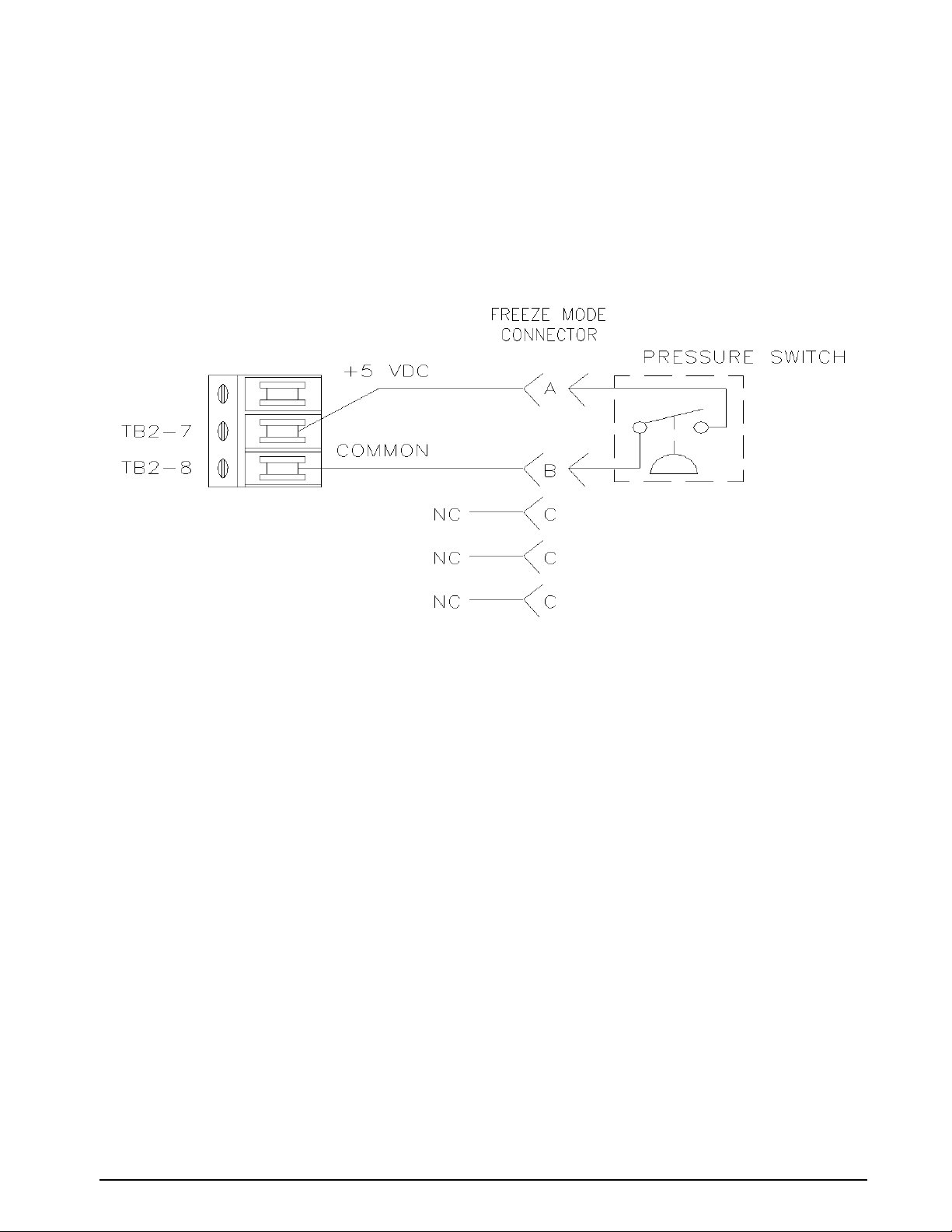
2.5 Freeze Mode Option Wiring
See Figure 2-7 on page 8 for TB location on CPU.
Connections may be made using the Freeze Mode Kit, see “Freeze Mode Option - PN 57778” on page 54. The
small five pin connector (pins A & B) which, in turn, are connected to the main CPU board via terminal bloc k
TB2-7 (+) (Pin A) and TB2-8 (Gnd Ret) (Pin B). The current through these wires is approximately 0.5 mA as a
non-inductive load. The voltage between these two wires is 5 VDC.
NOTE: Option may not be used with the APC4000/APC4001 Interface Option.
Figure 2-8. Freeze Mode Option Wiring
Operation 11
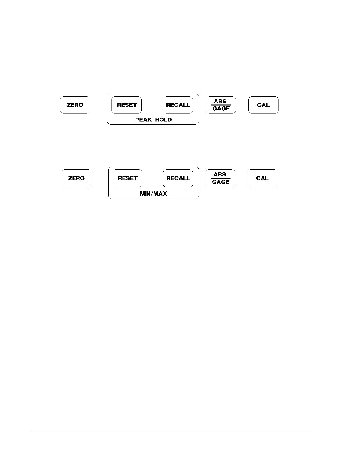
2.6 Engineering Conversion with PEAK HOLD or MAX/MIN Option
See Figure 2-7 on page 8 for location of “Data Enter” and rocker switches.
NOTE: When the PEAK HOLD or MAX/MIN option is supplied with a model having the ABS/GAGE mode, switch
selectable from front panel, the CONV button will be disabled and will not be present on the front panel.
Figure 2-9. Peak Hold Option Front Panel Switches
Figure 2-10. MIN/MAX Option Front Panel Switches
In order to step the light bar on conversion display to required conversion the following steps must be taken:
1. Open UPS3000/UPS3110/UPS3210 per Section 4.2.1 on page 28.
2. At this time, record the settings of rocker switches S1 and S3. These settings must be changed in order to
program the new conversion configuration.
3. Close the following rocker switches S1 position 3 and S3 positions 1 and 3.
4. Verify Numeric display has “1 XXX”, where X’s are some random number.
NOTE: If 1 is not on display open rocker switch S1 position 3 and rocker switch S3 positions 1 and 3, then restart at step
3 above.
5. Push the ABS/GAGE switch located on front panel as needed to move light bar on conversion disp lay to
required conversion.
6. Momentarily push the “Data Enter” switch S2 to enter new conversion.
7. Open the following rocker switches S1 position 3 and S3 positions 1 and 3.
NOTE: Verify rocker switches S1 and S3 conform to original settings which had been recorded earlier.
8. To verify proper conversion is active remove and restore power to the UPS3000/UPS3110/UPS3210.
12 UPS3000/UPS3110/UPS3210 Operation & Maintenance Manual

2.7 UPS3000 or UPS3210 Initial Setup Sequence
For UPS3000, refer to Figure 2-1 on page 5 and Figure 2-4 on page 6.
For UPS3210, refer to Figure 2-3 on page 6 and Figure 2-6 on page 8.
1. Connect the pressure source to the instrument via the INPUT PRESSURE port (16), 7/16-20, 37o-4 AN male
fitting provided on the rear panel. It is suggested that a Cheat Seal, PN 54854, be used between INPUT
PRESSURE port and pressure source fitting.
NOTE: Valves for venting and pressure input should be installed in line with the pressure source.
2. Apply power to the instrument using AC Cord (17) or, if applicable, by pressing POWER switch (13) on
front panel and allow it to stabilize for at least 5 to 10 minutes.
3. Select the desired full scale pressure range via the three-position rotary RANGE SELECT switch (6). For
the best accuracy, the selected range must be greater than, but close as possible to, the full scale range of
the Device-Under-Test.
NOTE: Do not switch pressure ranges during a pressure cycle.
4. If applicable or required, select the mode of operation by momentarily depressing the ABS/GAGE
push-button switch (2). The applicable “ABS” or “GAGE” light bar (4) will be lit to provide mode of
operation.
5. To select the desired measurement display units, depress CONV push-button switch (3).
NOTE: When the PEAK HOLD or MAX/MIN option is supplied with a model having the ABS or GAGE mode, switch
selectable from front panel, the “CONV” button will be disabled and will not be present on the front panel. Refer to
Section 2.6 on page 12.
6. If operating the unit in GAGE mode go to Section 2.7.1 or if operating the unit in ABS mode go to
Section 2.7.2.
Application of pressures greater than 1.5 times the highest pressure range of the indicator may cause
#AUTION
calibration errors or even permanent damage to the pressure transducer.
2.7.1 UPS3000 or UPS3210 Display of Pressure Sequence GAGE Mode
1. Vent the Input Pressure port (16) to atmosphere.
2. Momentarily depress the ZERO push-button switch (1). The display will indicate 0.00.
3. The instrument is now fully configured and ready to display the applied pressure.
2.7.2 UPS3000 or UPS3210 Display of Pressure Sequence Absolute (ABS) Mode
NOTE: If local barometric pressure is not 14.7, ABS/GAGE switch selectable units only, may need barometric offset. See
“Barometric Offset - Absolute/Gage Switch Selectable Units ONLY” on page 23.
1. If only pressure measurements greater than barometric are required, continue to Step 1.1. If pressure
measurements above and below atmospheric pressure are required go to step 2.
1.1.To apply pressure, close the customer supp lied vent valve attached in line with the INPUT PRESSURE port
(16). Unit will display applied pressure.
2. If pressure measurements above and below atmospheric pressure are required, connect a VACUUM
PUMP in line with the
INPUT PRESSURE port (16).
3. Close the customer supplied vent and input valve attached in line with the INPUT PRESSURE port (16).
4. Apply power to the vacuum pump and allow it to evacuate the system for several minutes or until the
digital display reading reaches equilibrium near Zero psia. Momentarily press the
ZERO push-button
switch (1) to establish a zero reference on the display.
5. The instrument is now fully configured and ready to display the applied pressure.
Operation 13

2.8 UPS3110 Initial Setup Sequence
Refer to Figure 2-2 on page 5 and Figure 2-5 on page 7.
1. Connect the pressure source to the instrument via the INPUT PRESSURE port (16), 7/16-20, 37o-4 AN male
fitting provided on the rear panel. It is suggested that a Cheat Seal, PN 54854, be used between INPUT
PRESSURE
2. Check that the INPUT valve (10) is closed (rotate clockwise until it stops) and that the VENT valve (12) is
open (two turns counter-clockwise from its stop).
3. Plug in the power cord (17) and energize the unit by pushing the POWER switch located on front panel.
Allow at least 10 minutes warm-up time.
4. Select the desired full scale pressure range via the three-position rotary RANGE SELECT switch (6). For
the best accuracy, the selected range must be greater than, but close as possible to, the full scale range of
the Device-Under-Test (DUT).
NOTE: Do not switch pressure ranges during a calibration cycle.
5. Using the PRESSURE LIMIT CONTROL regulator (7), adjust the maximum system input pressure, as read by
the
full-scale range of the DUT. Using this technique, the DUT is fully protected from being accidentally
over-pressurized.
NOTE: UPS3110 []A[] and UPS3110 []G[] units do not have PRESSURE LIMIT CONTROL or MONITOR.
6. Connect the male end of the test hose to the TEST PORT (9) fitting.
7. Connect the swivel fitting end (7/16-20) of the Test (output) hose to the DUT using adapters if required.
Tighten all connections properly.
8. If applicable or required, select the mode of operation by momentarily depressing the ABS/GAGE (2)
switch. The applicable “ABS” or “GAGE” light bar (4) will be lit to provide mode of operation.
9. To select the desired measurement display units, depress CONV (3) switch.
NOTE: When the PEAK HOLD or MAX/MIN option is supplied with a model having the ABS or GAGE mode, switch
selectable from front panel, the “CONV” button will be disabled and will not be present on the front panel. Refer to
Section 2.6 on page 12.
10. If operating the unit in GAGE mode go to Section 2.8.1 or if operating the unit in ABS mode go to
Section 2.8.2.
port and pressure source fitting.
PRESSURE LIMIT MONITOR (8), to any desired value higher (typically 20–50% higher) than the
2.8.1 UPS3110 Pressure Measurement Sequence GAGE Mode
1. Press the ZERO push-button switch (1), display will return to a normal “Zero” reading. The instrument
may be zeroed at anytime, as long as the
VENT valve (12) is open, by momentarily depressing the ZERO
push-button switch (1).
2. T o apply pressure, close the VENT valve (12), approximately two turn s, until it stops, then open the INPUT
valve (10) approximately 1/2 turn counter-clockwise until the numerical display begins to move. The
pressure may change rapidly until reaching approximately 90% of the desired final value.
3. Use either the INPUT (10) or VENT valve (12) to obtain a specific pressure reading. Both provide precise
control. As the pressure approaches the desired value, the valve being used for control should be rotated
slowly clockwise to its closed position. With a little experience, pressure values very close to the desired
final value may be quickly achieved.
4. To obtain exact pressure readings, slowly rotate the VERNIER control (11) knob in the direction required
(clockwise to increase pressure) as indicated by the electronic numerical display.
Application of pressures greater than 1.5 times the highest pressure range of the indicator may cause
#AUTION
calibration errors or even permanent damage to the pressure transducer.
14 UPS3000/UPS3110/UPS3210 Operation & Maintenance Manual

2.8.2 UPS3110 Pressure Measurement Sequence Absolute (ABS) Mode
NOTE: If local barometric pressure is not 14.7, ABS/GAGE switch selectable units only, may need barometric offset. See
“Barometric Offset - Absolute/Gage Switch Selectable Units ONLY” on page 23.
1. If only pressure measurements greater than barometric are required, continue to step 1.1. If pressure
measurements above and below atmospheric pressure are required go to step 2.
To apply pressure, close the VENT valve (12), approximately two turns, until it stops, then open the INPUT
valve (10) approximately 1/2 turn counter-clockwise until the numerical display begins to move. The
pressure may change rapidly until reaching approximately 90% of the desired final value.
1.1. Use either the INPUT (10) or VENT valve (12) to obtain a specific pressure reading. Both provide
precise control. As the pressure approaches the desired value, the valve being used for control should
be rotated slowly clockwise to its closed position. With a little experience, pressure values very close
to the desired final value may be quickly achieved.
1.2. To obtain exact pressure readings, slowly rotate the VERNIER control (11) knob in the direction
required (clockwise to increase pressure) as indicated by the electronic numerical display
Application of pressures greater than 1.5 times the highest pressure range of the indicator may cause
#AUTION
calibration errors or even permanent damage to the pressure transducer.
2. If pressure measurements above and below atmospheric pressure are required, connect a VACUUM
PUMP to the VACUUM/VENT port (19).
3. Open the VENT valve (12), close the INPUT valve (10) and apply power to the vacuum pump and allow it
to evacuate the system for several minutes or until the digital display reading reaches equilibrium near
Zero psia. Press the
ZERO push-button switch (1) to establish a zero reference on the display.
4. With the vacuum pump still running, close the VENT valve (12) (approximately two turns to its stop) and
check for system leaks. If there are none, continue to step 4.1.
4.1. To apply pressure, open the INPUT valve (10) (approximately 1/2 turn counter-clockwise until the
numerical display begins to move). In ge neral, the pressure m ay be changed rapidly until reaching
approximately 90% of it desired final value.
4.2. Use either the INPUT (10) or VENT (12) valve to obtain a specific pressure reading. Both provide
precise control. As the pressure approaches the desired value, the valve being used for control should
be rotated slowly clockwise to its closed position. With a little experience, pressure values very close
to the desired final value may be quickly achieved.
4.3. To obtain exact pressure readings, slowly rotate the VERNIER control (11) knob in the direction
required (clockwise to increase pressure) as indicated by the electronic numerical display.
2.9 GAGE Mode Self-Check
For UPS3000, refer to Figure 2-1 on page 5 and Figure 2-4 on page 6.
For UPS3110, refer to Figure 2-2 on page 5 and Figure 2-5 on page 7.
For UPS3210, refer to Figure 2-3 on page 6 and Figure 2-6 on page 8.
NOTE: Use of this Self -Check is not required for the proper operation of unit. CAL key is non-functional in absolute
mode due to the inability to simulate a perfect vacuum reference.
1. Vent the Input Pressure port (16) to atmosphere.
2. Momentarily depress the ZERO push-button switch (1). The display will indicate 0.00.
3. Momentarily depress the CAL push-button switch (5). The display will immediately blank except for two
“- -” which indicate that the unit is performing the self-check. If the self-check is successful, the display
will flash “
100.00” and revert to its normal zero indication.
Operation 15

2.10 Battery Operation
For replacement, see “Replacement Kits” on page 57.
When supplied with the battery, the UPS3000/UPS3110/UPS3210 has an internal, rechargeable 12 volt, lead
acid battery which provides a minimum of 6 hours of completely portable usage before having to be re-charged.
The UPS3000/UPS3110/UPS3210 may be operated and/or recharged by simply connecting to a standard AC
outlet via the line cord supplied. The battery re-charge cycle time is approximately 16 to 20 hours with the
OFF
switch in the OFF position. The charging circuit is designed to be left on indefinitely without adversely
ON/
affecting battery life.
The battery voltage reading will typically be between 11.5 and 12.6 volts. When the battery voltage reads 11.5
volts there are approximately 1 to 2 hours of useful operation left and a
red LED in the lower left corner of unit near the
POWER switch will turn on. The instrument will cease to
LOW BATT indicator will be illuminated. A
function when the battery voltage is 11.0 volts or less.
2.11 Serial Output: 20 mA Loop
NOTE: This may not be used with the following options in “DEMAND FORMAT”, APC4000 or APC4001 interface, Peak
hold, Min/Max or Battery. This may not be used with the following options in “CONTINUOUS FORMAT”, APC 4000 or
APC4001 interface or Battery.
Their are two modes of operation, Continuous or Demand.
Continuous Mode: Model is continuously sending data.
Demand Mode: Must be done from the front panel of the UPS3000/UPS3110/UPS3210 using a button. The
button is the hidden one between the
externally by PC.
CONV and CAL button’s This is not a two-way mode and cannot be done
2.11.1 Hardware Configuration
NOTE: See “Case Removal and Installation” on page 28.
UPS3000 Required Parts: PN 60607 Quantity 1, PN 58707 Quantity 1, PN 14839 Quantity 2, PN 58302,
Quantity 1.
UPS3110 and UPS3210 Required Parts: Contact factory for requirements.
NOTE: Because of soldering it may be beneficial to have this installed at factory.
Solder Brown Wire to E13 and Red Wire to E14
The serial output is accessed at J3, a 15-pin D-subminiature female connector at the rear of the unit. Pin
designations are as follows:
J3-8 +Tx (Brown wire)
J3-9 -Tx (Red Wire)
2.11.2 Serial Output Software Configuration
NOTES:
1. See “Case Removal and Installation” on page 28.
2. See Figure 2-7 on page 8 to locate DIP switches S1 and S3,as well as, switch S2 on CPU board.
3. See Figure 3-2 on page 20 for “STEPPER” and “ENTER” switch locations.
1. Open up the unit and power it up.
2. On the main circuit board, close S3-1. The unit will display the following:
6 0 _ X X X where “X” can be any number
3. Momentarily hit the STEPPER push-button switch until the number 64 is on the left side of the display.
The unit will display the following:
6 4 _ X X X where “X” can be any number
4. Refer to the “DATA FORMAT TABLE” in this section to determine the appropriate output format.
16 UPS3000/UPS3110/UPS3210 Operation & Maintenance Manual

5. At this time, record the settings of switch S1. These settings must be changed in order to program the
serial output configuration.
6. After the data format and baud rate have been selected, refer to the “SERIAL OUTPUT
CONFIGURATION TABLE” in this section for the appropriate values for the M.S.D. “M” and the
L.S.D. “L.”
7. Set up switch S1 with the data derived from the “Serial Output Configuration Table”.
8. After switch S1 has been set, push the ENTER button on front panel to enter the data.
9. The selected values for “M” and “L” should now appear at location 64 in the correct order. If this is not
the case, go back and perform step “7” and try again.
10. To store this information permanently, close switch S3-2. The unit will display the following:
_ 1 _ X X X where “X” can be any number
11. Push swit ch S2 momentarily. As switch S2 is held down, the XXX on the display (see step “10”) becomes
377. Release switch S2.
12. Return switch S1 to the original settings which had been recorded ea rlier in step “5”. Open switches on
switch S3 to resume normal operation.
2.11.3 DATA FORMAT TABLE
Format # 1 3 _ _ _ 0. 0 0 2 _ K G / C M 2 _ G <CR> <LF>
Format # 1 Data String
A) PRESSURE RANGE + 1 SPACE (IF POSITIVE DATA) OR "-" IF NEGATIVE
B) DATA* + 1 SPACE.
C) CONVERSION + 1 SPACE.
D) MODE + <CR> + <LF>.
Format # 2 3 _ 0 0 0 . 0 0 2 _ G <ST> <CR> <LF>
Format # 2 Data String
A) PRESSURE RANGE + 1 SPACE (IF POSITIVE DATA) OR “-” IF NEGATIVE
B) DATA* + 1 SPACE.
C) MODE + <ST> + <CR> + <LF>
<ST> Conversion Pressure Range Mode
“O” Over Range PSI mBar “1” High Range “G” Gage
“U” Under Range KPa cm H20 “2” Mid Range “A” Absolute
“M” Motion mm Hg
“ D” Default Bar in H2O
in Hg % F. S.
Table 2-7. Data Format Settings
<CR> CARRIAGE RETURN, <LF> LINE FEED
NOTE: * Data consists of seven characters including the decimal point. In format #1, leading zeros are located only one
character to the left of the decimal point. In format # 2, all unused characters will be leading zeros.
Kg/cm
2
“3” Low Range
Operation 17
2.11.4 SERIAL OUTPUT CONFIGURATION TABLE
EEPROM LOCATION 64
6 4 _ _ M L
LSD
M
0 0 0 0 0 Format #1 Demand
1 1 0 0 0 Format #2 Demand
2 0 1 0 0 Format #1 Continuous
3 1 1 0 0 Format #2 Continuous
S1 Settings
Serial Output Data Format1 2 3 4
Table 2-8. M Serial Output Configuration
LSD
L
0 0 0 0 0 300
1 1 0 0 0 600
2 0 1 0 0 1200
3 1 1 0 0 2400
4 0 0 1 0 4800
5 1 0 1 0 9600
5 6 7 8
S1 Setting
Serial Output
Baud Rate
Table 2-9. L Serial Output Configuration
0 = OPEN, 1 = CLOSED
MSD = MOST SIGNIFICANT DIGIT, LSD = LEAST SIGNIFICANT DIGIT
All serial characters are ASCII and consist of the following:
1 Start Bit
7 Data Bits
Odd Parity
2 Stop Bits
Table 2-10. Serial Character Settings
18 UPS3000/UPS3110/UPS3210 Operation & Maintenance Manual
3.0 Calibration and Adjustment Procedure
The simple step-by-step calibration sequence provided on the following pages will permit a qualified technician
to calibrate an entire UPS3000, UPS3110 or UPS3210 instrument in a matter of 45 minutes.
However, it must be strongly emphasized that when performing these tests, the computer within the instrument is
actually being re-programmed and as such, it is imperative that the pressure standard being used be in
satisfactory operating condition and that the technician fully understands its operating characteristics and
methods of usage. In addition, the
(approximately 10 minutes) and electrically stabilized prior to performing a calibration cycle.
NOTE: The CONDEC Repair Lab is equipped to do calibrations on CONDEC calibrators and pressure
standards.Calibrations include a certification and are traceable to N.I.S.T (see
Material Authorization Form”).
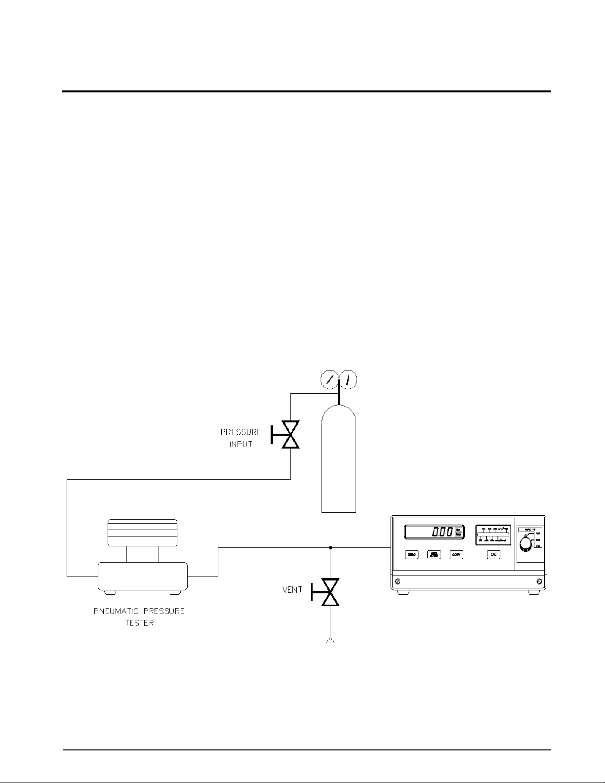
3.1 Pneumatic Calibration Set-Up
Figure 3-1 defines a typical gage or absolute/gage calibration set-up using a floating piston type dead weight
tester. While doing an ABSOLUTE Only Unit calibration, a vacuum pump with an indicator capable of reading
PSIA will be required where the dead weight tester/pressure source is shown in
below local barometric pressure.
NOTE: Any type of precision pressure or vacuum standard is acceptable as long as its basic accuracy is ±0.025% of
point or better.
To permit proper calibration at least an “ON/OFF” and a “VENT” valve, connected as shown in Figure 3-1 must
be provided.
UPS3000/UPS3110/UPS3210 itself must be properly warmed up
“UPS3000/UPS3110/UPS3210 Return
Figure 3-1. This enables going
Figure 3-1. Instrument Calibration Set-Up
NOTE: UPS3000 shown, AC Input and Pressure Ports are on back side of all models.
Calibration and Adjustment Procedure 19
3.2 Instrument Calibration Set-Up
NOTE: See“Case Removal and Installation” on page 28 and Figure 2-7 on page 8 to locate DIP switch S3 on CPU board.
UPS3000 is placed into its calibrate mode by momentarily opening instrument drawer and setting the DIP
switch, S3 in accordance with
UPS3110, disconnect the input pressure and power lines and remove the unit from its rack. Remove the top
cover. Set the DIP switch, S3 in accordance with
UPS3210, disconnect the input pressure and power lines and remove the unit from its rack. Remove the top
cover. Set the DIP switch, S3 in accordance with
0 0 0 0 Operate
1 0 1 0 Calibrate
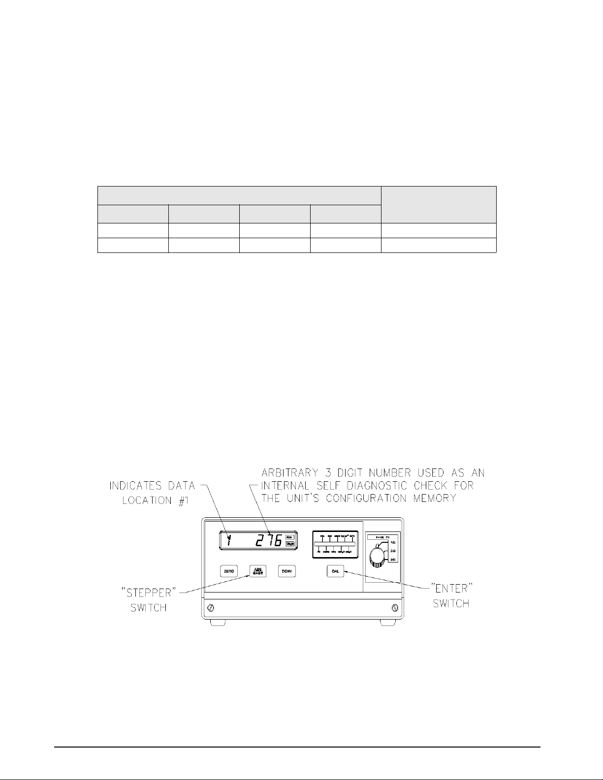
In the CALIBRATE mode the UPS3000/UPS3110/UPS3210’s digital displays are used to provide the operator with
prompting symbols, as well as displaying the various data formats employed. The front panel button switch,
under the middle of the display, becomes a sequential
functions (Zero/Span, Linearity/Hysteresis, Shunt Resister Calibration) and the push-button (CAL) directly
beneath the conversion display is used as the
All calibration functions will be performed in PSI engineering units, as “Gauge” (atmospheric reference)
measurements, unless the instrument being calibrated has been configured as an “Absolute Only” unit. If so, the
procedures in this section should be followed, except that an absolute (0 psia) reference must be utilized. A good
2-stage vacuum pump should be employed to attain greater than 100 microns Hg. vacuum.
Figure 3-2 depicts the location of the above described front panel switches as well as showing the display format
obtained as soon as the unit has been placed in the CALIBRATE mode.
Table 3-1. Connect Test Standard to UPS3000 Input Port.
Table 3-1 and connect Test Standard to UPS3110 Test Port.
Table 3-1 and connect Test Standard to UPS3210 Input Port.
Switch Settings S3
Program Switch ModePosition 1 Position 2 Position 3 Position 4
Table 3-1. CALIBRATE/OPERATE Switch Settings
STEPPER key used to select the various programming
ENTER switch.
Figure 3-2. Calibration Keys
NOTE: UPS3000 shown Input Port located on back of unit.
20 UPS3000/UPS3110/UPS3210 Operation and Maintenance Manual
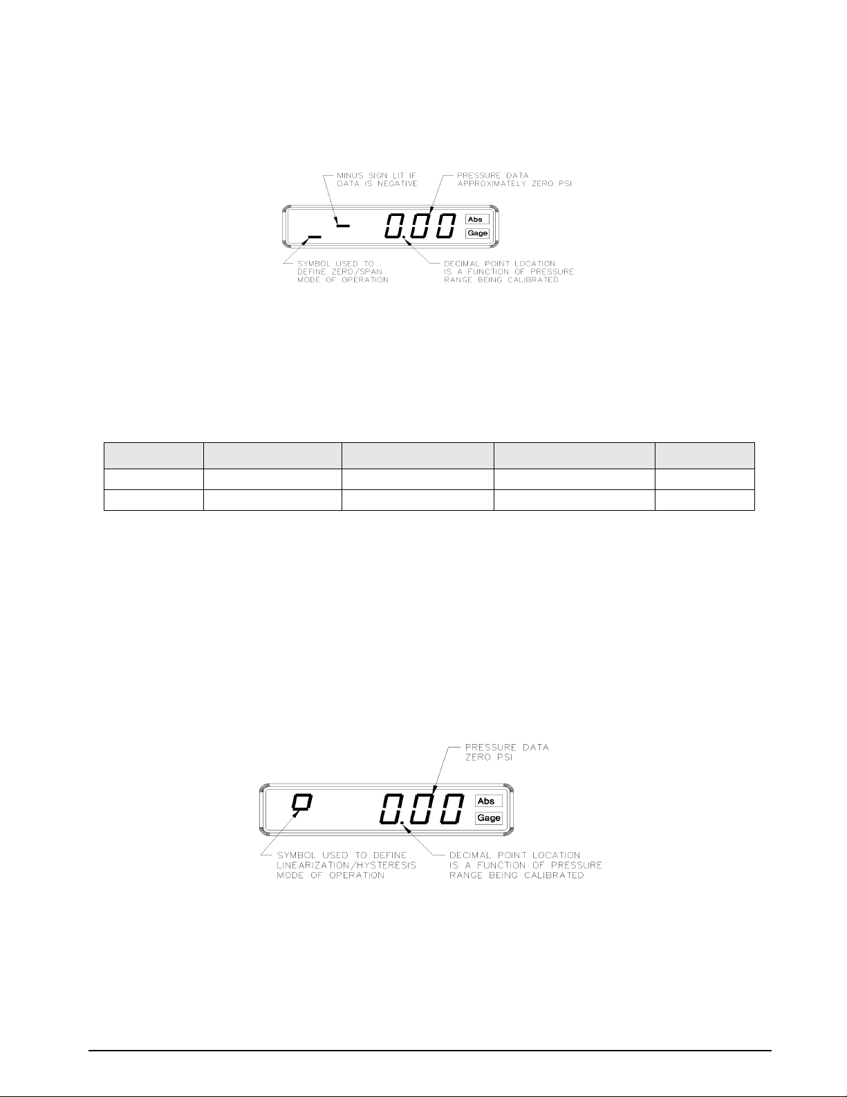
3.3 Zero/Span Calibration
Pressing the STEPPER push-button switch once places the instrument into its ZERO/SPAN calibration mode. The
display will be shown in
Starting with the instrument’s lowest pressure range, sequentially perform steps 1 and 2 shown in Table 3-2 for
each pressure range. Perform the following for each step.
NOTE: Perform Step 1 in all ranges prior to doing Step 2.
1. Adjust input pressure to the appropriate (either 0 or 100%) value.
2. Perform the action indicated by the table when pressure input readings are stable.
Step Number Pressure Input Valve Operator Action Required Resulting Display Indication Remarks
1 0% Press ENTER Switch 0% Note 1
2 100% Press ENTER Switch 100% Note 2
Figure 3-3.
Figure 3-3. Zero/Span Calibration for Gage Only Units (Each Range)
Table 3-2. Zero and Span Calibration Sequence
NOTES:
1. If readings are not stable or are not within ± 20% of zero, the zero correction cannot be entered.
2. If readings are not stable or are not within ± 5% of 100%, the span correction cannot be entered.
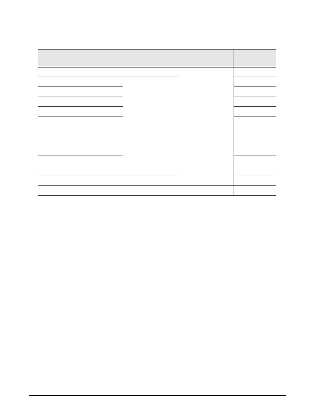
3.4 Linearity and Hysteresis Calibration
The unit can be placed in LINEARIZATION/HYSTERESIS mode by pressing the STEPPER push-button under the
middle of the display as shown in
NOTE: The zero/span calibration needs to be performed prior to linearity and hysteresis calibration. For Absolute Only
Unit, vacuum pump with PSIA indicator must be used to obtain readings below local barometric pressure.
Figure 3-2. The display is shown in Figure 3-4.
Figure 3-4. Linearity and Hysteresis Calibration
Starting with the instrument's lowest pressure range, sequentially perform the thirteen steps described in
Table 3-3 on page 22, for each pressure range being calibrated. Perform the following for each step.
1. Adjust input pressure to the appropriate value without overshooting the setting.
Calibration and Adjustment Procedure 21
2. Perform the action as indicated when the readings are stable.
INPUT PRESSURE,
STEP NO.
1 0 Press ZERO Switch “Upper Circle” Zero on Display
2 10 Press ENTER Switch Notes 1 & 2
3 20 Notes 1 & 2
4 30 Notes 1 & 2
5 40 Notes 1 & 2
6 50 Notes 1 & 2
7 60 Notes 1 & 2
8 70 Notes 1 & 2
9 80 Notes 1 & 2
10 90 Notes 1 & 2
11 100 No Action Required “Lower Circle” Note 3
12 50 Press ENTER Switch Notes 1 & 2
13 0 No Action Required “L”
% OF RANGE
OPERATOR ACTION
REQUIRED
STATUS SYMBOL IN
LEFT MOST DIGIT
REMARKS
Table 3-3. LINEARIZATION & HYSTERESIS CALIBRATION SEQUENCE
When step number 11 is reached, the display will change so that the left most status symbol will be “H”. This
will remain for step 12 and down to approximately 0.00 psi.
NOTES:
1. If reading is in motion or correction required is not within ±0.8% of Full-Scale, no entry will be made.
2. If entry is valid, the display will momentarily indicate the correction value (in percent) and the memory location at
which it is stored.
3. If 100% ±0.05% is not obtained, repeat the Zero/Span calibration sequence.
22 UPS3000/UPS3110/UPS3210 Operation and Maintenance Manual
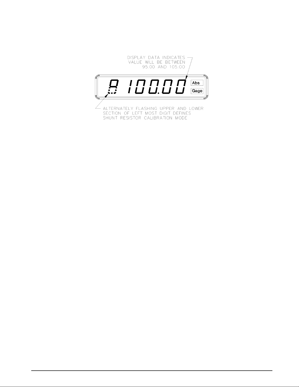
3.5 Shunt Resistor Calibration
Press the STEPPER push-button again to select the SHUNT RESISTOR CALIBRATION mode. The display will be as
shown in
With the UPS3000/UPS3110/UPS3210’s highest pressure range selected, perform the four step sequence
described below:
NOTE: For Absolute Only Unit, vacuum pump with PSIA indicator must be used to obtain zero reading.
Figure 3-5.
Figure 3-5. Shunt Resistor Calibration
1. Be sure the input pressure to the UPS3000/UPS3110/UPS3210 is at zero psig.
2. Press and hold the ZERO push-button switch on the front panel until a stable zero indication is obtained.
3. Release the ZERO push-button switch and allow the display to stabilize at its shunt resistor calibration
number, (100 ± 5.00%).
4. Press the ENTER push-button switch, as shown in Figure 3-2 on page 20, on the front panel. If accepted,
the bottom half of all display digits will momentarily illuminate.
3.6 Permanent Data Storage
After completing the above calibration procedures, the new data that has been entered into the computer must
be permanently stored. The sequence to do this is as follows:
1. Pressing the STEPPER push-button again, as shown in Figure 3-2 on page 20, will bring the indicator
back to its initial Data Recall display condition as shown in Figure 3-2.
2. Open the instrument and depress the DATA ENTER switch, S2, located approximately in the middle of the
circuit board.
NOTE: See “Case Removal and Installation” on page 28 and for "DATA ENTER" switch location see Figure 2-7 on
page 8.
3. If the data is accepted, the three-digit number on the right side of the display will indicate 1 377 for as
long as the
DATA ENTER switch, S2, is depressed.
4. The calibration is now complete and CALIBRATE /O PER ATE switch, S3, must be returned to its normal
operating positions as shown in
Table 3-1 on page 20. The pressure standard may now be disconnected.
3.7 Barometric Offset - Absolute/Gage Switch Selectable Units ONLY
NOTES: This section is only required if barometric conditions are higher or lower than 14.7 PSIA.
See“Case Removal and Installation” on page 28. See Figure 2-7 on page 8 for S3, CALIBRATE/OPERATE
configuration switch and S2 "DATA ENTER" switch location. See Figure 3-2 on page 20 for STEPPER and ENTER
push-button switch locations.
If required, obtain the current barometric pressure from a pressure standard with an accuracy of.025% or better,
to calibrate the absolute zero at the current barometric pressure. Remove top cover and
switch, S3, must be changed to its calibrate positions as shown in
Table 3-1 on page 20. Using the STEPPER
push-button place the unit into ZERO/SPAN calibration mode as shown in Figure 3-3 on page 21.
CALIBRAT E/ OPE RAT E
Calibration and Adjustment Procedure 23

3.7.1 For UPS3000/UPS3210 Absolute/Gage Switch Selectable Units ONLY
If the current barometric pressure is below 14.7 PSIA, the offset is positive, see Example 1. If the current
barometric pressure is above 14.7 PSIA, the offset is negative, see Example 2. If the current barometric pressure
is 14.7 PSIA, then no offset is needed.
Example 1:
If the current barometric pressure is lower than 14.70 PSIA, subtract the current barometric pressure from 14.70.
14.70 PSI: UPS3110 reference point
-14. 55 PSI: Current barometric pressure
0.15 PSI: Positive Delta Offset
Complete the following steps
NOTE: UPS3000 refer to Figure 2-1 on page 5 and Figure 2-4 on page 6. UPS3210 refer to Figure 2-3 on page 6 and
Figure 2-6 on page 8.
1. Connect Test Standard to UPS3000/UPS3210 Input Port similar to Figure 3-1 on page 19.
2. Open the vent valve connected between Test Standard and UPS3000/UPS3210.
3. Using the RANGE SELECT switch (6), select the lowest pressure range on the UPS3000/UPS3210.
4. Press the ENTER push-button, as shown in Figure 3-2 on page 20, on the UPS3000/UPS3210. The
display reads zero. Repeat this step for the middle and high ranges.
5. Close the vent valve connected between Test Standard and UPS3000/UPS3210. Select the lowest
pressure range of the UPS3000/UPS3210.
6. Input a pressure into the UPS3000/UPS3210 until the display reads the value of the Positive Delta
Pressure, 0.15 PSI as in this example.
7. Depress the ENTER push-button on the UPS3000/UPS3210. The display reads zero. W ithout touching the
input pressure repeat this step for the middle and high ranges.
8. Using the STEPPER push-button, as shown in Figure 3-2 on page 20, place the unit into SHUNT RESISTOR
CALIBRATION mode. The display will be as shown in Figure 3-5 on page 23.
9. With UPS3000/UPS3210 RANGE SELECT switch (6) switched in the high range, depress the ZERO
push-button on the front panel. Verify that the display reads 0.00. Upon release of the push-button the
display will be as shown in Figure 3-5 on page 23.
10. Depress the ENTER push-button. The display will respond with “[] [] [] [] [] []” until the button is
released.
11. Pressing the STEPPER push-button bring the indicator back to its initial Data Recall display condition as
shown in Figure 3-2 on page 20. The display shows 1 XXX (three arbitrary digits).
12. Depress the DATA ENTER switch, S2, located approximately in the middle of the circuit board. See Figure
2-7 for the switch location.
13. If the data is accepted, the three-digit number on the right side of the display will indicate 377 for as long
as the DATA ENTER switch, S2, is depressed.
14. The barometric offset is now complete and CALIBRATE/OPERATE switch, S3, must be returned to its
normal operating positions as shown in
disconnected.
Table 3-1 on page 20. The Test Standard may now be
24 UPS3000/UPS3110/UPS3210 Operation and Maintenance Manual
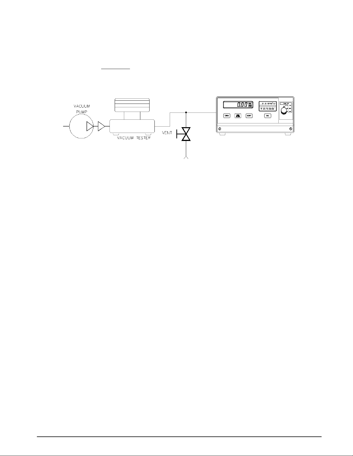
Example 2:
If the current barometric pressure is above 14.70 PSIA, subtract the current barometric pressure from 14.70.
14.70 PSI: UPS3110 reference point
-14.75 PSI: Current barometric pressure
-.05 PSI: Negative Delta Offset
Figure 3-6. Vacuum Pump Setup
Complete the following steps:
NOTE: UPS3000 refer to Figure 2-1 on page 5 and Figure 2-4 on page 6. UPS3210 refer to Figure 2-3 on page 6 and
Figure 2-6 on page 8.
1. Connect Vacuum Test Standard to UPS3000/UPS3210 Input Port similar to Figure 3-6. A vacuum pump
will need to be connected such that the Vacuum Test Standard controls the ou tput coming from the
vacuum pump going into the
INPUT PRESSURE port (16) of the UPS3000/UPS3210.
2. Open the vent valve connected between Test Standard and UPS3000/UPS3210.
3. Using the RANGE SELECT switch (6), select the lowest pressure range on the UPS3000/UPS3210.
4. Press the ENTER push-button, as shown in Figure 3-2 on page 20, on the UPS3000/UPS3210. The
display reads zero. Repeat this step for the middle and high ranges.
5. Close the vent valve connected between Vacuum Test Standard and UPS3000/UPS3210. Select the
lowest pressure range of the UPS3000/UPS3210.
6. Turn the vacuum pump on creating a vacuum. Using the Vacuum Test Standard to control the vacuum
until the UPS3000/UPS3210 display reads the value of the Negative Delta Pressure, -0.05 PSI as in this
example.
7. Depress the ENTER push-button on the UPS3110. The display reads zero. Without touching the Vacuum
Test Standard settings repeat this step for the middle and high ranges.
8. Using the STEPPER push-button, as shown in Figure 3-2 on page 20, place the unit into SHUNT RESISTOR
CALIBRATION mode. The display will be as shown in Figure 3-5 on page 23.
9. With UPS3000/UPS3210 RANGE SELECT switch (6) switched in the high range, depress the ZERO
push-button on the front panel. Verify that the display reads 0.00. Upon release of the push-button the
display will be as shown in
Figure 3-5 on page 23.
10. Depress the ENTER push-button. The display will respond with “[] [] [] [] [] []” until the button is
released.
11. Pressing the STEPPER push-button bring the indicator back to its initial Data Recall display condition as
shown in
12. Depress the DATA ENTER switch, S2, located approximately in the middle of the circuit board. See Figure
2-7 for the switch location
13. If the data is accepted, the three-digit number on the right side of the display will indicate 377 for as long
as the
14. The barometric offset is now complete and CALIBRATE/OPERATE switch, S3, must be returned to its
normal operating positions as shown in
disconnected.
Figure 3-2 on page 20. The display shows 1 XXX (three arbitrary digits).
DATA ENTER switch, S2, is depressed.
Table 3-1 on page 20. The Va cuum Test Standard may now be
Calibration and Adjustment Procedure 25