

Page 1

UVC1000/UVC1010
Table Top & Rack-mountable Pneumatic
Vacuum Generator/Pressure Controller
Operation and Maintenance
Manual
Condec Sales Phone Number: (888) 295-8475
Condec Web Site: www.4condec.com
69481
Page 2

Contents
About This Manual. . . . . . . . . . . . . . . . . . . . . . . . . . . . . . . . . . . . . . . . . . . . . . . . . . . . . . 1
1.0 Introduction. . . . . . . . . . . . . . . . . . . . . . . . . . . . . . . . . . . . . . . . . . . . . . . . . . . . . . 1
2.0 Operation. . . . . . . . . . . . . . . . . . . . . . . . . . . . . . . . . . . . . . . . . . . . . . . . . . . . . . . . 3
2.1 Input Air Pressure Supply. . . . . . . . . . . . . . . . . . . . . . . . . . . . . . . . . . . . . . . . . . . . . . . . . 3
2.2 Pressure Measurement Sequence. . . . . . . . . . . . . . . . . . . . . . . . . . . . . . . . . . . . . . . . . . 3
3.0 Maintenance . . . . . . . . . . . . . . . . . . . . . . . . . . . . . . . . . . . . . . . . . . . . . . . . . . . . . 4
3.1 Troubleshooting . . . . . . . . . . . . . . . . . . . . . . . . . . . . . . . . . . . . . . . . . . . . . . . . . . . . . . . . 4
3.2 Test and Maintenance Procedures . . . . . . . . . . . . . . . . . . . . . . . . . . . . . . . . . . . . . . . . . 4
3.2.1 Test Procedure. . . . . . . . . . . . . . . . . . . . . . . . . . . . . . . . . . . . . . . . . . . . . . . . . . . . . . . . . . . 4
3.2.2 UVC1000/UVC1010 Cover - Removal and Installation . . . . . . . . . . . . . . . . . . . . . . . . . . . . . 4
3.2.3 Pressure Limit Control (PN 58409) - Regulator Removal and Installation. . . . . . . . . . . . . . . . 5
3.2.4 Vacuum Monitor (PN 59230) and Pressure Limit Monitor (PN 59706) Gauges -
Removal and Installation. . . . . . . . . . . . . . . . . . . . . . . . . . . . . . . . . . . . . . . . . . . . . . . . . . . . 5
3.2.5 Pressure and Vacuum Port Quick-Connect Fitting (PN 59997) -
Removal and Installation. . . . . . . . . . . . . . . . . . . . . . . . . . . . . . . . . . . . . . . . . . . . . . . . . . . . 6
3.2.6 Input Port (PN 59761) - Removal and Installation . . . . . . . . . . . . . . . . . . . . . . . . . . . . . . . . . 6
3.2.7 Input Port Filter (PN 54188) - Removal, Cleaning and Installation . . . . . . . . . . . . . . . . . . . . . 7
3.2.8 Vacuum Generator (PN 57960) - Removal, Cleaning and Installation . . . . . . . . . . . . . . . . . . 8
4.0 Specifications. . . . . . . . . . . . . . . . . . . . . . . . . . . . . . . . . . . . . . . . . . . . . . . . . . . . 9
UVC1000/UVC1010 Warranty and Return Policy . . . . . . . . . . . . . . . . . . . . . . . . . . . . . . 10
UVC1000/UVC1010 Return Material Authorization Form. . . . . . . . . . . . . . . . . . . . . . . . 11
Copyright © 2001 Rice Lake Weighing Systems. All rights reserved. Printed in the United States of America.
Specifications subject to change without notice.
September 2001
Page 3

About This Manual
The UVC1000/UVC1010 is a rugged, compact
instrument manufactured by Condec, designed to
provide ease of operation, for the calibration of a wide
variety of pressure sensing and measuring devices.
Equipped to perform rapid on-site calibrations, these
instruments have proven to substantially reduce the
cost, system down-time and man-hours of labor
normally associated with these routine service
functions.
This instrument is an all-mechanical device that
provides up to 29 inches Hg vacuum in areas that are
off limits to vacuum pumps.The operator uses e xisting
shop air lines working with a built in vacuum
converter inside the unit. The unit has multiple ports,
including one for low pressure and one for vacuum.
Front panel gages tell the operator system pressure. A
pressure regulator will act as a pressure limiter so that
the operator can not over pressure a unit under test.
Adapter fittings are supplied for the customer to put
on their fill hose and test hose.
This manual has been written to give the user a simple
and clear explanation of how to operate, and
troubleshoot these instruments.
While a substantial effort has been
Warning
dangerous conditions could be produced through
negligent handling or operation of the
UVC1000/UVC1010.
These units are strictly for use with pneumatic
pressures. Erroneous readings and potential
damage could result from the introduction of
hydraulic fluids into the internal tubing lines.
expended to make this equipment
safe, simple and fool-proof to
operate, it is strongly
recommended that only personnel
formally trained in the use of
pneumatic pressure equipment be
permitted to operate it. Potentially
Authorized distributors and their
employees can view or download this
manual from the Condec distributor
site at
www.4condec.com
.
1.0 Introduction
The UVC1000/UVC1010 offers a combination of features, performance, versatility and reliability. Some of the
more outstanding features are listed below:
• Two models available: table top and 19" rackmount.
• Portable: These compact, self-contained systems are easily carried and operated by only one person. Total
weight is approximately 7 pounds.
• An internal input filter: Easily removed for inspection and cleaning.
• Simple Operation: All control regulator, gages, vacuum port and pressure port are accessible from the front
panel. The input port is located on the rear of unit. Accompan ying operator's manual pro vides clear , concise
instructions for system operation.
• Safe, Clean Operation: All pressure components are made of brass, aluminum or stainless steel and
proof-tested to at least 150% of maximum operating pressure.
Overpressure protection and clean line pressure must be provided by the customer. By virtue of this technique,
the UVC1000/UVC1010 and unit under test is fully protected from being inadvertently overpressurized.
Introduction
1
Page 4
2
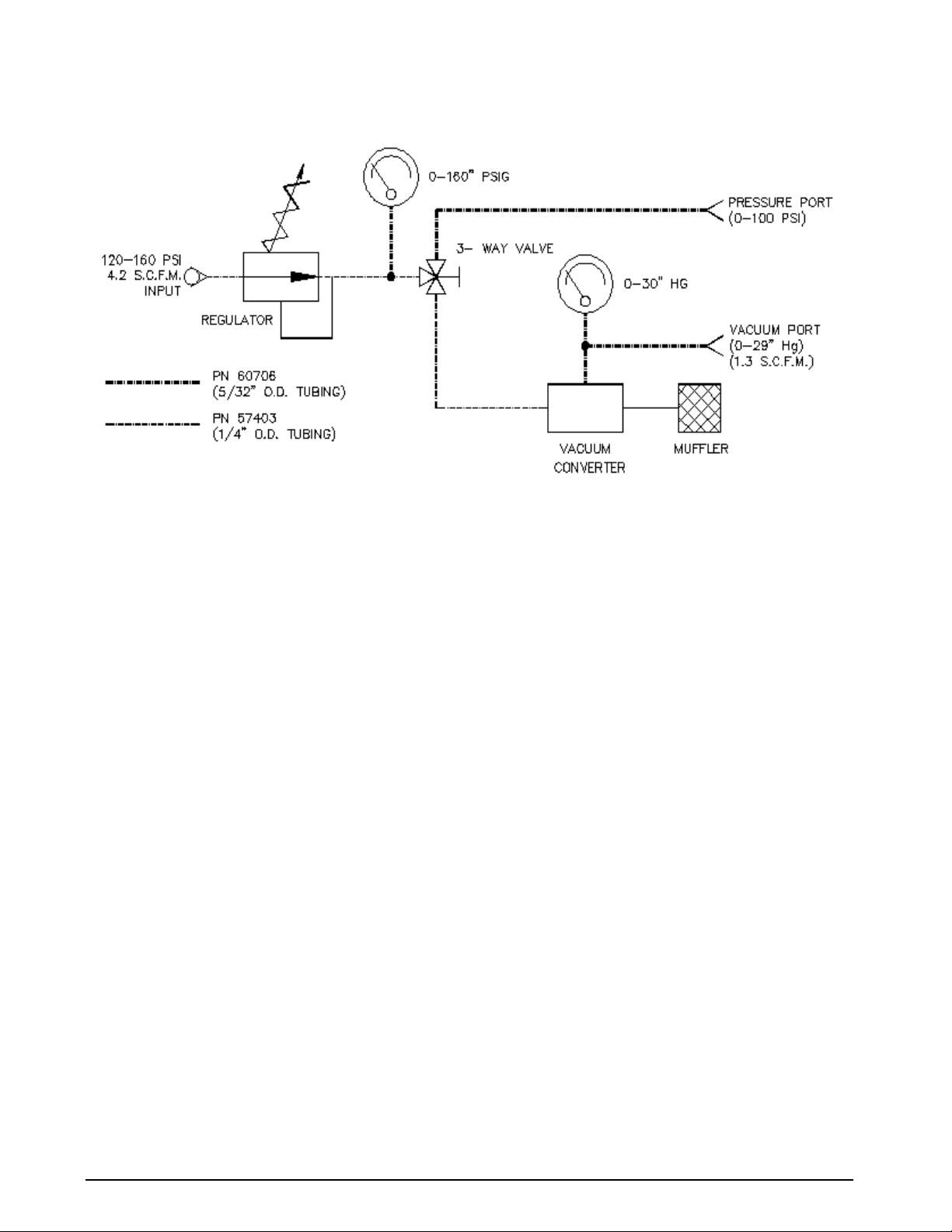
The following schematic provides an overview of the UVC1000/UVC1010’s function.
Figure 1-1. UVC1000/UVC1010 Flow Diagram
UVC1000/UVC1010 Operation and Maintenance Manual
Page 5
2.0 Operation
2.1 Input Air Pressure Supply
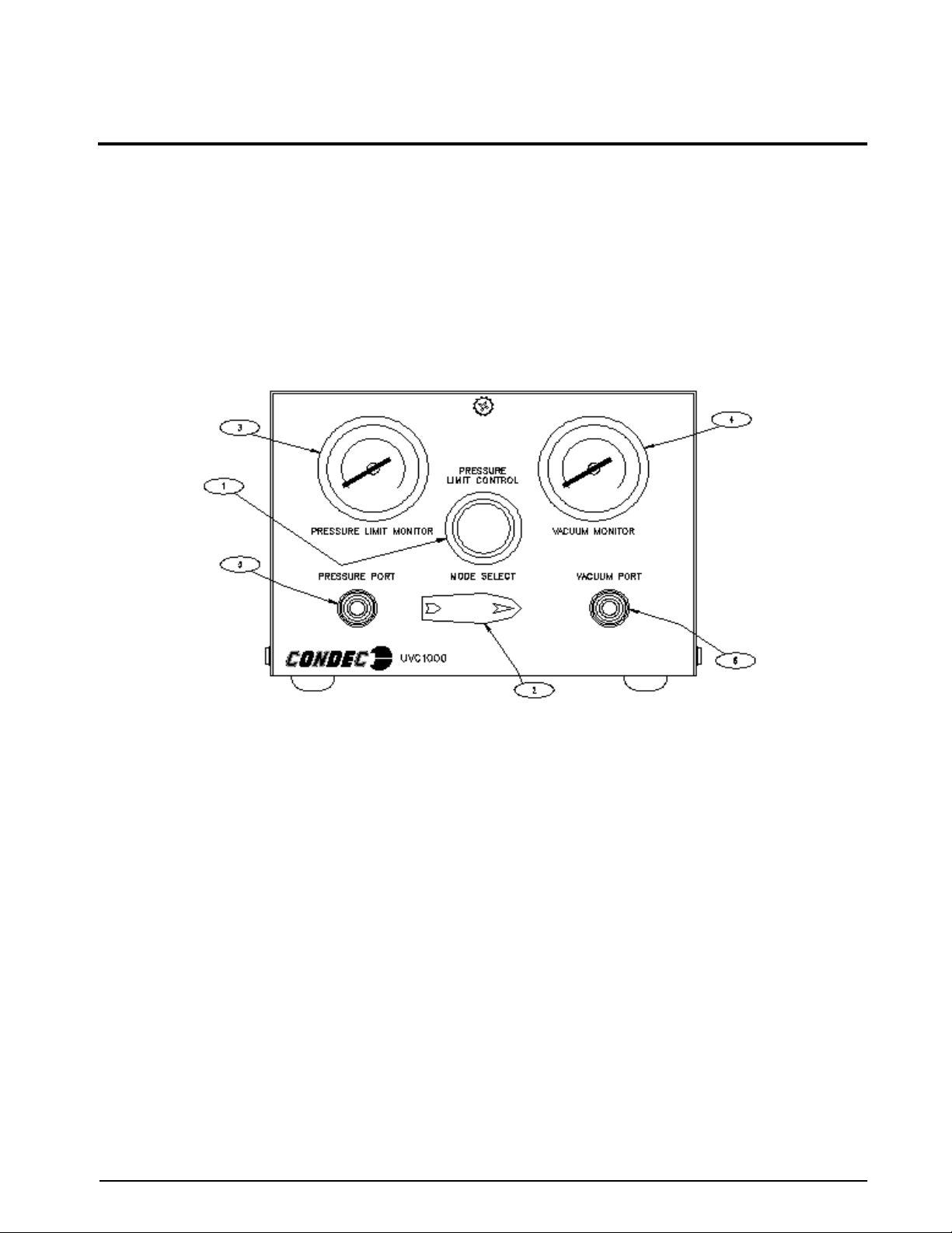
See Figure 2-1 below and proceed as described below.
NOTE:
PSIG.
The air pressure source used must have a vent valve and be regulated to provide a maximum output of 160
1. Pull
PRESSURE LIMIT CONTROL
(1) knob outward and rotate counter-clockwise until it stops.
2. Connect the input hose, supplied by customer, to a clean regulated shop air source.
3. Connect the other end of the input hose, supplied by customer, to the male input port fitting located on
rear of unit. Use a customer supplied AN-4 37° adapter fitting, and cheat seal pad (recommended)
between input hose & input port.
Figure 2-1. Input Operation Procedure
NOTE:
UVC1000 shown, UVC1010 Rack Mount unit also has an input port on back of unit.
2.2 Pressure Measurement Sequence
To prepare for actual calibration usage, see Figure 2-1 above and proceed as follows:
1. Check that the
until it stops). Turn MODE SELECT knob to the required mode of operation.
2. Connect the male quick disconnect end of the port hose, supplied by customer, to one of the ports,
Pressure Port (5) or Vacuum Port (6). Use supplied 1/4 female NPT quick disconnect fitting, (PN 60195)
between port hose and Pressure Port or Vacuum Port.
3. Connect the other end of the port hose, supplied by customer, to the unit under test, using adapters if
required. Tighten all connections properly.
4. Set the customer regulated input pressure to a maximum of 160 PSI.
5. Pressure Mode: Using the
pressure, as read by the PRESSURE LIMIT MONITOR (3), to any desired value (100 PSI max.) within
scale range of the device under test. Using this technique, the device under test is fully protected from
being accidentally over-pressurized.
Vacuum Mode: Using the
pressure, as read by the VACUUM MONITOR (4), to any desired value within scale range of the device
under test (-29 in Hg max).
PRESSURE LIMIT CONTROL
PRESSURE LIMIT CONTROL
PRESSURE LIMIT CONTROL
valve (1) is closed (pull knob outward and rotate clockwise
regulator (1), adjust the maximum system input
regulator (1), adjust the maximum system input
Operation
3
Page 6
4
3.0 Maintenance
3.1 Troubleshooting
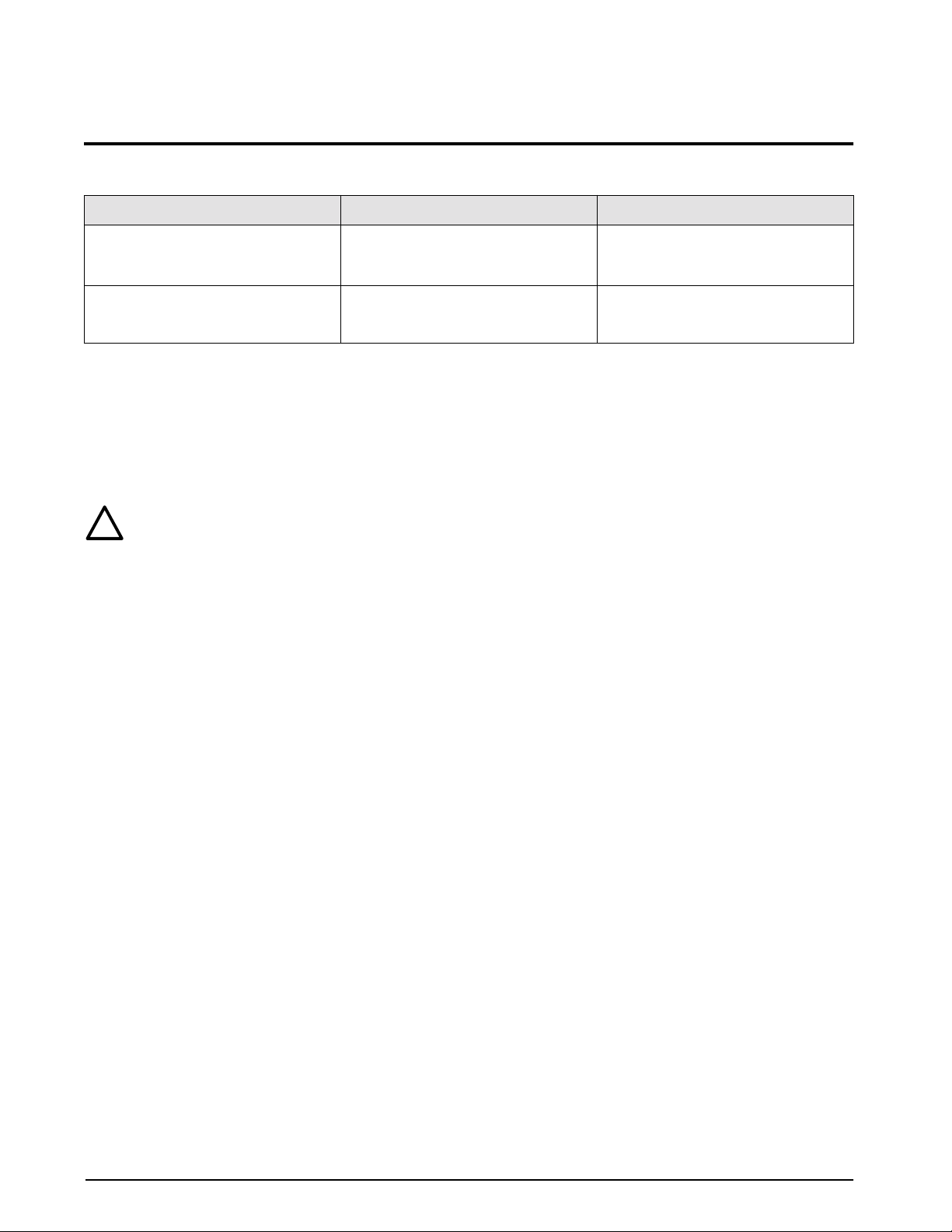
Symptom
Pressure Limit Monitor gauge or Vacuum
Monitor gauge slowly decreases over
time
Applicable gauge does not respond
when Pressure Limit Control knob is
turned
Table 3-1. UVC1000/UVC1010 Troubleshooting
Leak in system Check all compression and pipe fittings
No regulator control Try other mode of operation. If o.k,
Problem Remedy
with soap solution or Snoop
64781)
replace gauge, otherwise replace
Pressure Limit Control regulator
®
(PN
3.2 Test and Maintenance Procedures
This section outlines the test and mechanical repair procedures for the UVC1000/UVC1010 Vacuum
Generator/Pressure Controller. The repair procedures cover the major components and subassemblies which are
critical to the proper functioning of the UVC1000/UVC1010 and that will likely need periodic maintenance over
the life of the unit.
Only those persons who are formally trained as skilled technicians should attempt to repair these
Caution
!
3.2.1 Test Procedure
Tools required: Snoop
1. Remove cover from its enclosure as described in Section 3.2.2, and place on a bench top.
NOTE:
Do not remove Input hose.
2. Verify MODE SELECT is on PRESSURE, turn knob to the left.
3. Connect shop air to the unit, at the INPUT, on the rear of the unit.
NOTE:
PSIG.
The air pressure source used must have a vent valve and be regulated to provide a maximum output of 160
4. Pull out the PRESSURE LIMIT CONTROL, until you hear a click. Turn the knob clockwise until you
get a reading of 100 PSI. Push knob inward.
5. Check all pipe connections for leaks by using Snoop
6. Turn the MODE SELECT to VACUUM mode slowly.
7. Verify the vacuum gage is reading -28.5 to 29 psi.
NOTE:
(maximum 160 PSIG).
The air pressure source and PRESSURE LIMIT CONTROL may have to be increased to obtain reading
8. Install cover on its enclosure as described in Section 3.2.2.
units. Although some mechanical sub-assemblies could be replaced without venting line pressure, it
is not recommended. All safety precautions should be observed.
®
, liquid leak gas detector (PN 64781)
®
.
3.2.2 UVC1000/UVC1010 Cover - Removal and Installation
Tools required: Phillips screwdriver
UVC1000 Cover Removal:
1. Vent input line pressure and remove input and port hoses.
2. Pull out the PRESSURE LIMIT CONTROL knob, until you hear a click. To close regulator, rotate knob
counter-clockwise, until it stops. Push knob inward.
3. Loosen and remove the six screws (PN 14839) that secure the cover to the enclosure.
4. Lift and remove the cover.
UVC1000/UVC1010 Operation and Maintenance Manual
Page 7

UVC1000 Cover Installation:
1. Vent input line pressure.
2. Pull out the PRESSURE LIMIT CONTROL knob, until you hear a click. Close regulator, rotate knob
counter-clockwise, until it stops. Push knob inward.
3. Replace and align cover.
4. Install and tighten the six screws (PN 14839) that secure the cover to the enclosure.
5. Replace input hose, if not previously attached.
UVC1010 Cover Removal:
1. Vent input line pressure and remove input and port hoses.
2. Pull out the PRESSURE LIMIT CONTROL knob, until you hear a click. To close regulator, rotate knob
counter-clockwise, until it stops. Push knob inward.
3. Loosen and remove the two scre ws (PN 14839) on front of panel (1) and on rear of unit (1). These secure
the cover to the enclosure.
4. Lift and remove the cover.
UVC1010 Cover Installation:
1. Vent input line pressure.
2. Pull out the PRESSURE LIMIT CONTROL knob, until you hear a click. Close regulator, rotate knob
counter-clockwise, until it stops. Push knob inward.
3. Replace and align cover.
4. Install and tighten the two screws (PN 14839) that secure the cover to the enclosure.
5. Replace input hose, if not previously attached.
3.2.3 Pressure Limit Control (PN 58409) - Regulator Removal and Installation
Tools required: 7/16” open end wrench
hex wrench (.186")
channel locks
A/R 1/4" wide Teflon tape, (PN 60575)
Removal:
1. Remove cover from its enclosure as described in Section 3.2.2 on page 4, and place on a bench top.
2. Note the orientation and remove the tubing sections that connect to the regulator inlet and outlet fittings.
3. Loosen and remove regulator mounting nut from the front of panel, by using channel locks.
NOTE:
Be careful not to scratch front of panel.
4. Note the orientation, then remove the regulator by sliding out from the panel rear.
5. Note the orientation of the inlet and outlet fittings in the regulator. Remove the fittings and any remnants
of Teflon tape from the pipe threads.
Installation:
1. Wrap two layers of Teflon tape on the pipe threads of each fitting and install into the inlet and outlet of
the regulator and ensure that each is oriented properly.
2. Insert the new regulator into the panel through rear of panel and rotate to proper position. Thread and
tighten the mounting nut onto the regulator body from the panel front.
3. Attach the tubing sections to the inlet and outlet fittings.
4. Test UVC1000/UVC1010 as described in Section 3.2.1 on page 4.
Maintenance
5
Page 8

6
3.2.4 Vacuum Monitor (PN 59230) and Pressure Limit Monitor (PN 59706) Gauges - Removal and Installation
Tools required: 7/16" wrench
9/16" wrench
A/R 1/4" wide Teflon tape (PN 60575)
Removal:
1. Remove cover from its enclosure as described in Section 3.2.2 on page 4, and place on a bench top.
2. Disconnect the tubing section that connects to the gauge fitting.
3. Loosen the two thumb-nuts that hold the gauge mounting U-clamp.
4. While gripping the square portion of the gauge port with the 9/16" wrench, remove the female tube
connector (PN 57695) from the gauge.
5. Remove the two thumb-nuts, the mounting U-clamp, and the gauge.
Installation:
1. Before installing a new gauge, wrap two layers of new Teflon tape on the port.
2. Install gauge into panel, secure with U-clamp and tighten the two thumb screws.
3. While gripping the square portion of the gauge port with the 9/16" wrench, tighten the female tube
connector onto the gauge.
4. Attach the tubing section that connects to the gauge fitting.
5. Test UVC1000/UVC1010 as described in Section 3.2.1 on page 4.
3.2.5 Pressure and Vacuum Port Quick-Connect Fitting (PN 59997) - Removal and Installation
NOTE: If there is leakage out of the port, replace the test port quick-connect
Tools required: 1/2" open end wrench
5/8" open end wrench
11/16" open end wrench
A/R 1/4" wide Teflon tape (PN 60575)
A/R 1/2" wide Teflon tape (PN 60911)
Removal:
fitting.
1. Remove cover from its enclosure as described in Section 3.2.2 on page 4, and place on a bench top.
2. From inside of front panel, disconnect the tubing section that connects to the female tube connector (PN
57695) fitting.
3. Grasp the hex nut at the panel face with a 5/8" wrench and using a 1/2" wrench on the female tube
connector fitting on inside of front panel, turn the female tube connector fitting counter-clockwise and
remove.
4. Grasp the hex nut at the panel face with a 5/8" wrench and using a 11/16" open end wrench on the lock
nut on rear side of panel, turn the lock nut counter-clockwise. Slide quick-connect fitting out of panel
from front.
Installation:
1. Before installing a new Quick-Connect Fitting, wrap two layers of new Teflon tape on the port.
2. Install the quick-connect fitting through front of panel. Thread and tighten lock nut on quick-connect
fitting, from inside of front panel.
3. Thread and tighten female tube connector (PN 57695) fitting into port.
4. Attach the tubing section that connects to the female tube connector fitting.
5. Test UVC1000/UVC1010 as described in Section 3.2.1 on page 4.
UVC1000/UVC1010 Operation and Maintenance Manual
Page 9

3.2.6 Input Port (PN 59761) - Removal and Installation
Tools required: Phillips screwdriver
7/16" open end wrench
9/16" open end wrench
5/8" open end wrench
Removal:
1. Remove cover from its enclosure as described in Section 3.2.2 on page 4, and place on a bench top.
2. From inside of back panel, disconnect the tubing section that connects to the male tube connector (PN
57705) fitting.
3. Remove the AN bulkhead end nut and ferrules, note orientation, from AN bulkhead fitting.
4. Remove from bulkhead, but leave assembled, tube adapter (PN 56223) and male tube connector (PN
57705) fittings. Remove filter (PN 54188) from inside tube adapter fitting.
5. Using a wrench on the AN bulkhead lock nut from inside of back panel, turn the lock nut
counter-clockwise. Slide input port AN bulkhead fitting out from outside of back panel.
Installation:
1. Before installing a new input port AN bulkhead fitting, remove the end nut and ferrules (note orientation)
from AN bulkhead fitting.
2. Slide input port AN bulkhead fitting in from outside of back panel. Adjust the AN bulkhead fitting to
line-up with the fastener.
3. Thread AN bulkhead lock nut and turn clockwise finger tight.
4. If required, install hex plate fastener (PN 59712) over AN bulkhead input port fitting and onto rear panel,
with screw (PN 14845). Adjust the AN bulkhead fitting to line-up the screw hole with the fastener.
5. Using a 5/8" wrench on the AN bulkhead lock nut from inside of back panel, turn the lock nut clockwise
to tighten.
6. Install filter (PN 54188) inside tube adapter fitting (PN 56223).
7. From inside of back panel, install the AN bulkhead end nut and ferrules (in proper orientation) on AN
bulkhead fitting. Thread end nut loosely.
8. Slide assembled, tube adapter (PN 56223) and male tube connector (PN 57705) fittings (with filter) into
AN bulkhead fitting.
9. Tighten the AN bulkhead end nut approximately 1-1 /4 turns beyond finger tight, using 9/16" wrench.
10. Attach the tubing section that connects to the male tube connector (PN 57705) fitting.
11. Test UVC1000/UVC1010 as described in Section 3.2.1 on page 4.
3.2.7 Input Port Filter (PN 54188) - Removal, Cleaning and Installation
The port filter is a sintered element filter that can be easily removed for inspection and cleaning.
Tools required: 7/16" open end wrench
9/16" open end wrench
A/R solvent (de-natured alcohol)
Removal and Cleaning:
1. Remove cover from its enclosure as described in Section 3.2.2 on page 4, and place on a bench top.
2. From inside of rear panel, remove the AN bulkhead tubing end nut and ferrules (note orientation) from
input port AN bulkhead fitting. Remove filter (PN 54188) from inside tube adapter fitting (PN 56223).
NOTE:
Leave fittings attached to tubing.
3. Clean the filter in solvent (de-natured alcohol) and blow-dry with compressed air.
Installation:
1. Slide filter into fractional tube adapter fitting (PN 56223), attached to nylon tubing.
2. Slide tubing end nut and ferrules in proper order over AN bulkhead fitting. Thread end nut loosely.
Maintenance
7
Page 10

8
3. Slide fractional tube adapter fitting into input port AN bulkhead fitting
(PN 59761),
from inside of rear
panel.
4. Tighten the AN bulkhead end nut approximately 1-1 /4 turns beyond finger tight, using 9/16" wrench.
5. Test UVC1000/UVC1010 as described in Section 3.2.1 on page 4.
3.2.8 Vacuum Generator (PN 57960) - Removal, Cleaning and Installation
The vacuum generator is a Venturi device which creates a vacuum flow by use of a regulated air flow. The
generator can be removed for cleaning should any contamination be found.
Tools required: Phillips screwdriver
7/16" open end wrench
A/R 1/4" wide Teflon tape (PN 60575)
A/R 1/2" wide Teflon tape (PN 60911)
Removal and Cleaning:
1. Remove cover from its enclosure as described in Section 3.2.2 on page 4, and place on a bench top.
2. Note the orientation and remove the tubing sections that connect to the vacuum generators inlet and
outlet port fittings.
3. Remove and set aside the two mounting screws (PN 60811) that hold the vacuum generator to the rear
panel.
4. Unscrew the air inlet port elbow (PN 57708) and vacuum outlet port tee fitting (PN 57701). Remove any
remnants of Teflon tape from the pipe threads.
5. Using a wrench, unthread and remove the muffler (PN 56056) from the vacuum generator exhaust port.
Remove any remnants of Teflon tape from the pipe threads.
6. Blow clean dry compressed air through all passages to remove contamination.
Installation:
1. Wrap two layers of Teflon tape on vacuum generators air inlet port elbow and vacuum outlet port tee
fittings.
2. Install and tighten the fittings into the vacuum generator inlet and outlet ports.
3. Wrap two layers of Teflon tape on the muffler port. Using a wrench thread and tighten muffler into the
vacuum generator exhaust port.
4. Mount vacuum generator to inside of rear panel, using two screws (PN 60811). Muffler to be positioned
toward bottom of chassis and parallel with front panel VACUUM PORT marking.
5. Install the tubing sections that connect to the vacuum generator inlet port and outlet port fittings.
6. Test UVC1000/UVC1010 as described in Section 3.2.1 on page 4.
UVC1000/UVC1010 Operation and Maintenance Manual
Page 11
4.0 Specifications
Models:
UVC1000 (PN 56085): Table Top Unit
UVC1010 (PN 59415): 19” Rack Mount Unit
Operating Temperature:+40° to +110°F (+4.4° to +43.3° C)
Storage Temperature: 0° to +185° F (–17.8° to +85°C)
Pressure Media: Filtered shop air
Pressure Limit Monitor Gage:
Size: 2-in. diameter
Range: 0–160 PSIG
Pressure Media Filter:
Rating: 20 microns nominal
Type: Field replaceable
Internal Piping:
T ubing: 5/32 in. O.D., 0.025 in. wall thickness,
275 PSI working pressure rated.
1/4 in. O.D., 0.035 in. wall thickness,
250 PSI working pressure rated.
Couplings: Brass
Input Port:
Style: 1/4" 37° AN flare male
Pressure Rating: 3000 PSIG rated
Material: Brass
Pressure & Vacuum Port:
Pressure Rating: 2000 PSIG rated
Material: Brass
Pressure Hose Fittings:
Quantity Supplied: Two; one each for Pressure and
Vacuum port fittings.
Style: Quick-disconnect male one end, 1/8
NPT female on the other
Input, Pressure and Vacuum port
hoses are supplied by customer.
Enclosure:
Type: Steel case with cover
Material thickness: 0.059 in., nominal
Finish: Tan enamel paint, smooth finish.
Front of case black silkscreen
nomenclature.
UVC1010 Control Panel:
Material: Aluminum (5052-H32)
Thickness: 0.125 in.
Finish: Tan enamel paint, smooth finish, with
black silkscreen nomenclature.
Physical Specifications:
UVC1000 Weight: 6.6 lb (2.9 kg)
UVC1010 Weight: Approx. 7 lb (3 kg)
UVC1010 Control Panel Dimensions:
Height: 7” (177.8 mm)
Width: 19” (482.6 mm)
Depth: 7.03” (178.56 mm)
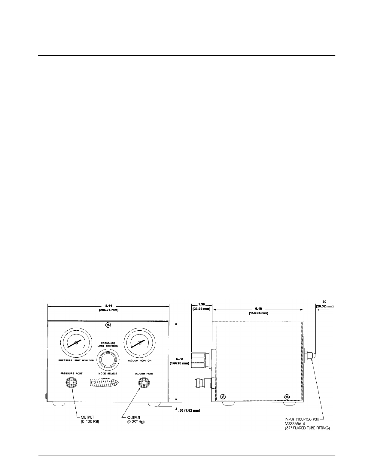
Enclosure Dimensions:
See Figure 4-1 on page 9 below.
Pressure Limit Control Regulator:
Type: Single stage, self-venting
Pressure Rating: 3000 PSIG max. inlet
Figure 4-1. Enclosure Dimensions
Page 12

10
UVC1000/UVC1010 Warranty and Return Policy
If possible, please save original packing material which is specifically designed for the unit. Should it be
necessary to ship the unit back to the factory, a suitable shipping container must be used along with sufficient
packing material. Do not put a shipping label on the unit as a "suitable shipping container." Some units ha v e been
severely damaged this way. This is a delicate, precision instrument. Any damage incurred because of poor
packaging procedures will ultimately result in added service charges and longer turn-around times.
Vent all pressure lines to the atmosphere before shipping.
Warning
When factory service is required, send in only the unit for repair. Retain fittings, manuals, etc. at your facility.
However, if there is a problem with a particular part, send in that part with the unit.
If a unit is found to be defective, it may be returned to our repair facility at the following address:
CONDEC
3 SIMM LANE
DOOR D, UNIT 2A
NEWTOWN, CT 06470
ATTN: PRESSURE PRODUCTS/REPAIR LAB
Each unit's I.D. plate is stamped with a date code (week/year) prior to shipment. Our warranty is twelve (12)
months from that date code and includes repair and/or replacement of the unit at our, Newtown facilities at no
charge. Units subjected to abuse or damaged by external influences, are not covered under warranty.
If the unit is found to be out of warranty, an evaluation char ge of not less than fifty (U.S.) dollars ($50.00) will be
charged. Please note on any attached paperwork if a repair estimate is required or if there are any other specific
instructions.
Please be explicit as to the nature of the problem and/or its symptoms. Your documentation will save needless
time and expense. Also, please include a return shipping address (with a street address) and a contact name with
fax and telephone numbers. Contact numbers are necessary to provide a job estimate and in case further
questions arise at the factory.
UVC1000/UVC1010 Operation and Maintenance Manual
Page 13
UVC1000/UVC1010 Return Material Authorization Form
The repair lab is also equipped to do calibrations on our calibrators and pressure standards. Calibrations include
a certification and are traceable to N.I.S.T.
COMPANY NAME:
STREET:
CITY, STATE, ZIP:
TELEPHONE:
FAX:
CONTACT PERSON:
MODEL NUMBER: _______________ SERIAL NUMBER: ______________________________
PROBLEM WITH UNIT (PLEASE BE SPECIFIC):
IS THIS A WARRANTY REPAIR? ( ) YES ( ) NO
SHIP TO Address:
COMPANY NAME:
STREET:
CITY, STATE, ZIP:
ATTN:
CONDEC • 3 SIMM LANE • DOOR D, UNIT 2A • NEWTOWN, CT 06470
ATTN: PRESSURE PRODUCTS/REPAIR LAB
TEL: 888-295-8475 • FAX: 203-364-1556 or 715-234-6967
WEB SITE: www.4condec.com
11
 Loading...