

Page 1

DLR334
PRESSURE INDICATOR
DUPLEX
SERIAL PROTOCOL
PAGE 1 74845
Page 2

CONTENTS
1.0 GENERAL……………………………………………………………… 3
2.0 FULL DUPLEX PROTOCOL……………………………………….… 3
3.0 COMMAND CODE <cmd> DESCRIPTION………………………… 3
4.0 DATA FORMAT…………………………………………………………4
5.0 RESPONSE…………………………………………………………….. 4
6.0 CHECK OPTION……………………………………………………….. 6
7.0 RS485…………………………………………………………………… 6
8.0 COMMAND CODE SUMMARY………………………………………. 6
9.0 RECALLED DATA…………………………………………………….. 9
10.0 STATUS RECALLED…………………………………………………. 10
11.0 CAPACITY/RESOLUTION ENTRY AND RECALL……………….. 11
12.0 BASE UNITS ENTRY AND RECALL……………………………….. 11
13.0 CALIBRATION…………………………………………………………. 11
14.0 SETUP DATA…………………………………………………………… 12
14.1 GENERAL………………………………..…………………………….. 12
14.2 COMMANDS……………………………………………………………. 12
14.3 PRESSURE………………………………………………………………13
14.4 FILTER SETUP………………………………………………………….13
14.5 PORT 1 SERIAL SETUP………………………………………………. 13
14.6 PORT 2 SERIAL SETUP………………………………………………. 14
14.7 INPUT SETUP………………………………………………………….. 14
14.8 TIME/ DATE SETUP…………………………………………………… 14
14.9 PARALLEL SETUP……………………………………………………. 15
14.10 ANALOG
SETUP……………………………………………………….. 15
14.11 SETPOINT (TRIP POINT)
SETUP……………………………………. 15
15.0 TEMPERATURE CALIBRATION…………………………………….. 16
16.0 COMMAND CODE LISTING BY ALPHABETICAL ORDER……… 18
PAGE 2 74845
Page 3

DLR334 PRESSURE DUPLEX SERIAL PROTOCOL
1.0 GENERAL:
! This document applies to the basic Pressure program KDG-1.
! The duplex protocol includes the following basic functions:
♦ Setup entry and recall.
♦ Current pressure data recall.
♦ Calibration and correction recall and entry.
♦ All front panel key functions.
♦ Temperature calibration and correction recall and entry.
! The protocol between the “standard” full duplex and the RS485 will only differ by the addition of
the origin and destination address characters.
! The protocol will be designed to be expandable for future growth and special applications.
2.0 FULL DUPLEX PROTOCOL:
Communications from the host computer into the DLR:
*<DD><OO><cmd><{><data entry><}><CHECK><CR>
Response from the DLR:
:<OO><DD><cmd r><{><data resp><}><CHECK><CR>
Where:
“<”,”>” Brackets are not sent
* = Message from master (host computer)(2AH).
: = Response from DLR (3AH).
DD = DLR unit address (two digit) if in RS485.
OO = Master address (fixed at 00) if in RS485.
If RS485 mode not selected the “DD” and “OO” are not transmitted.
Cmd = Three character command to DLR.
Cmd r = Three character command echoed from DLR.
{= Start of data character (7BH).
}= End of data character (7DH).
‘{‘ and ‘}’ only sent if data entry or recall.
Data entry= Data entered into DLR if entry command.
Data resp = Data response from DLR if in response.
CHECK = Optional two character check if selected.
CR = Message terminator (0DH).
A “LF” character following the “CR” will be ignored. All characters following
the “CR” and preceding the “*” will be ignored.
3.0 COMMAND CODE <cmd> DESCRIPTION:
The <cmd> consists of three (3) characters “ppt” where:
pp = the command parameter.
T = the command type.
The three (3) command types (t) are as follows:
Direct cmd code = < D > character (44H).
‘D’ Commands have no data associated with them.
PAGE 3 74845
Page 4

Data request code = < R > character (3FH).
Data entry code = < E > character (45H).
For complete listing of command codes see Table II.
4.0 DATA FORMAT:
4.1 GENERAL:
! When data is transmitted it is always bracketed with the ‘{‘ and ‘}’ characters.
! The separation character ‘|’ (7CH) is used to separate data in a string.
! All DLR recalled data has leading zero suppression with the zeros transmitted as spaces.
! All data entered into the DLR can have leading zero suppression with the zeros transmitted
as spaces but is not required.
! Summary of data formats:
PRESSURE: <value><units><par><stat>
STATUS:
SETUP: <par 1>|<par 2>| - - - <par x>
♦ General commands (Zero, etc.).
♦ Display commands (Min,Max, etc.).
♦ Pressure calibration (Zero Cal, etc.).
‘R’ commands requesting data from the host to the DLR.
♦ Pressure data.
♦ Status.
♦ Setup data.
Calibration data.
‘E’ commands with data sent from host to be entered into the DLR.
♦ Setup data.
♦ Calibration data.
WEIGHT: <stat>
INPUT: <I1>|<I2>
OUTPUT: <O1>|<O2>
5.0 RESPONSE:
! In the print/port 1/duplex setup the response by the DLR from the direct commands and data entry
commands can be selected for ‘None’ or Echo’.
‘None’: no response is given a direct cmd (D) or data entry cmd (E) if valid or invalid.
‘Echo’: the command (direct or entry) is echoed as received if valid; the start of transmission
character is returned with a ‘:’ not the ‘*’ character. If invalid a _NAK_ is returned
‘Ack/Nak’: instead of echoing back the received command code and entered data the DLR
responds with ‘ACK’ (41H, 43H & 48H) in place of the code. If an error in received data is
detected the DLR responds with ‘NAK’(4EH, 41H & 48H).
! An invalid input consists of the following:
Response in Echo or Ack/Nak mode = :NAK<CR>
Ack response: :ACK<CR>
Nak response: :NAK<CR>
♦ Parity error.
♦ Check error if enabled.
♦ Invalid command code.
♦ Invalid data format.
PAGE 4 74845
Page 5
! Commands received as valid but that can not be performed:
A valid command in the Echo or Ack/Nak mode that can not be performed will respond with:
:NAC<CA>
The conditions that give you a ‘NAC’ response are:
♦ Not in a valid mode for the command. For example, a ’Cal’ command in the
‘normal (run)’ mode (Refer to Command Performance Status Table Below).
♦ The Command is acting on a parameter that is disabled in Configuration. For
example, Peak data recall command when the Peak is configured for ‘off’.
(Refer to Command Performance Status Table I Below).
♦ The command is acting on a parameter that can not be performed due to the
unit conditions such as motion or over range.
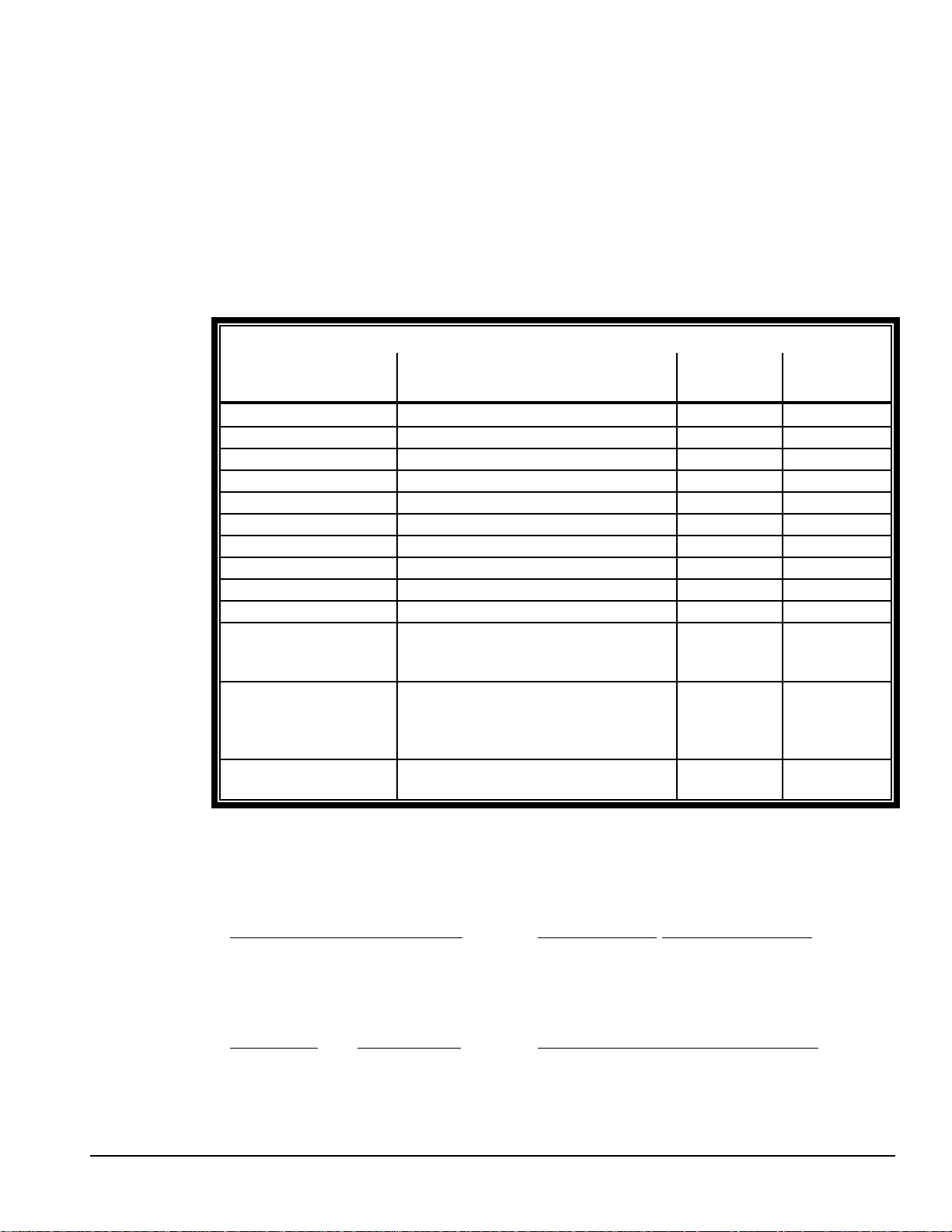
COMMAND ‘PERFORM’ STATUS TABLE I
CATEGORY COMMANDS
GENERAL ZED, TAD R UN YES
DATA RECALL PDR, PGR RUN/CAL N O
DATA RECALL PNR, PWR, PPR, PMR, PVR, PHR R U N YES
STATUS RECALL PSR, MSR, ISR, OSR R UN YES
DISPLAY SELECT MGD RUN/CAL N O
DISPLAY SELECT MND, MPD, MMD RU N YES
UNITS SELECT UxD RU N YES
UNITS SELECT UUE/UUR CAL NO
PRINT PR D RUN YES
CAPACITY/RES CPE/CPR, REE/RER CAL N O
CALIBRATION ZRD, RxD, LxE, ZFE/ZFR,
LXE/LXR, LFE/LFR, LCE/LCR , HCE,
HFE/HFR
SETUP SUE/SUR, FLE/FLR, P2E/P2R,
INE/INR, TME/TMR, DTE/DTR,
TIE/TIR, PAE/PAR, ANE/ANR,
TNE/TNR
TEMPERATURE CAL TPD, TXD, TRD, TFR, RZD, RSD,
HxD, CxD, TxE/TxR
MODE
VALID
CAL NO
CAL -
CAL NO
CONFIG.
ENABLED
! Protocol of responses:
♦ Direct cmd code: cmd = *<cmdD ><CR>
RESPONSE VALID ENTRY INVALID ENTRY
(NONE) = (NONE) (NONE) (NONE)
(ECHO) = :<cmd D><CR> :NAK<CR> :NAC<CR>
(ACK) = :ACK <CR> :NAK<CR> :NAC<CR>
♦ Data request code: cmd = *<cmdR><CR>
RESPONSE VALID ENTRY INVALID ENTRY CAN NOT PERFORM
(NONE) = :<cmdR><{data}><CR> (NONE) (NONE)
(ECHO) = :<cmdR><{data}><CR> :NAK<CR> :NAC<CR>
(ACK) = :<cmdR><{data}><CR> :NAK<CR> :NAC<CR>
♦ Data entry code: cmd= *<cmdE><{data}><CR>
CAN NOT PERFORM
PAGE 5 74845
Page 6
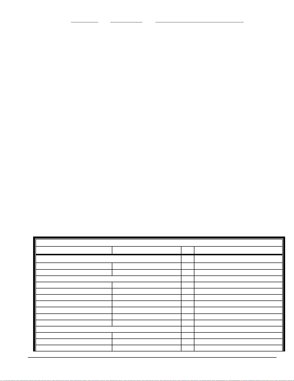
RESPONSE VALID ENTRY INVALID ENTRY CAN NOT PERFORM
)
(NONE) = (NONE) (NONE) (NONE)
(ECHO) = :<cmdE><CR> :NAK<CR> :NAC<CR>
(ACK) = :ACK<CR> :NAK<CR> :NAC<CR>
6.0 CHECK OPTION:
The check option is setup in the print duplex mode of port 1. It can be applied to the duplex serial in
the RS485 mode or in non addressable mode.
If check setup is set for ‘NONE’ (OFF), no characters are transmitted for check.
Checksum: if checksum is selected the check consists of two ASCII characters.
♦ All ASCII characters including the starting character and terminating character preceding
the checksum is included in the checksum.
♦ The ASCII characters are binary summed (not including the parity bit).
♦ The least significant byte is divided into four bits each “nibbles” and 30H is added to
each. Therefore a sum of 5EH will be transmitted as 35H and 3EH or ‘5>’.
Xor: if exclusive or is selected the check consists of two ASCII characters.
♦ All ASCII characters preceding the checksum are exclusively or’ed together.
♦ The check byte is then calculated to give a result of zero when it is exclusively or’ed in.
♦ The check byte is divided into four bits each and 30H is added to each.
7.0 RS485:
The RS485 protocol is the same as the standard duplex except the two character destination address
and two character origin address is included after the starting character.
The host computer’s address is fixed at ‘00’ and the DLR address can be set between 1 and 98.
When the setup is not set for the RS485 mode the RS485 transceiver is set for transmit only (RS422
applications).
8.0 COMMAND CODE SUMMARY:
The Response is shown in the ‘Ack/Nak’ mode.
The ‘D’ column represents the data character length including the ‘|’ seperator but not the ‘{‘or’}’
brackets.
COMMAND CODE SUMMARY TABLE II
COMMAND RESPONSE D DESCRIPTION
GENERAL:
ZED ACK TAD ACK - Tare. ;later
WEIGHT/PRESSURE/RATE DATA RECALL:
PDR PDR {pr,units,par,stat} 11 Display data recall.
PGR PGR {pr,units,par,stat} 11 Pressure recall.
PVR PVR {pr,units,par,stat} 11 R.P.M. recall
PHR PHR {pr,units,par,stat} 11 HP recall
PNR PNR {pr,units,par,stat} 11 ∆T recall. ;later
PPR PPR {pr,units,par,stat} 11 Max data recall.
PMR PMR {pr,units,par,stat} 11 Min data recall.
STATUS RECALL:
PSR PSR {stat} 1 Pressure status recall (motion, etc.
MSR MSR {units,mode} 3 Unit/mode status recall.
ISR ISR {I1|I2} 3 Input status recall.
Zero.
PAGE 6 74845
Page 7
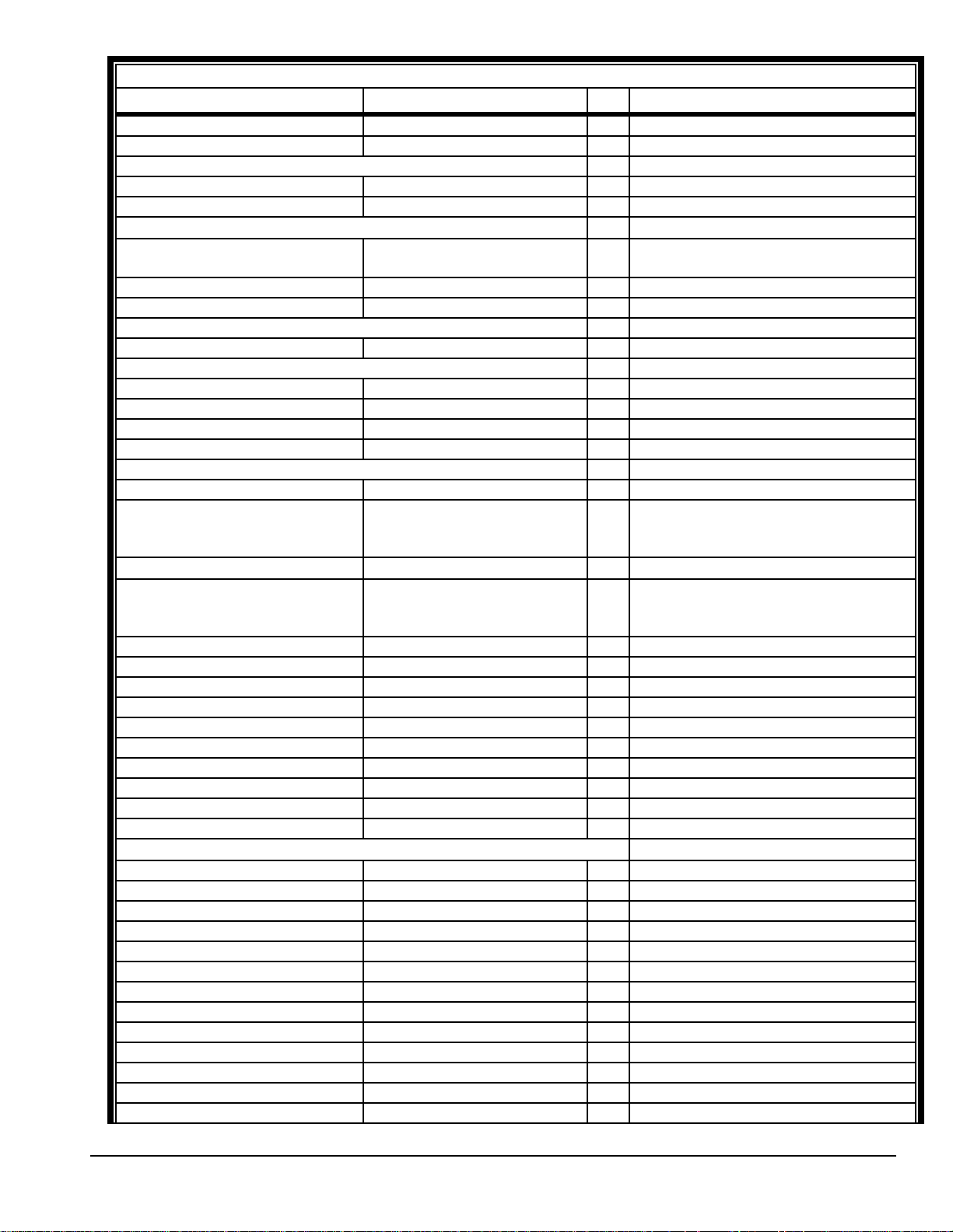
COMMAND CODE SUMMARY TABLE II
COMMAND RESPONSE D DESCRIPTION
OSR OSR {o1|o2} 3 Output status recall. :later
DISPLAY:
MPD ACK - Display to Max mode. ;later
MMD ACK - Display to Min mode. ;later
UNITS:
UxD ACK - Conv. Select units (x=A,B,C etc. per
Table III)
UUE {unit1| unit2} ACK 1 Base ‘Cal’ units entry.
UUR UUR {unit1|unit2} 3 Base ‘Cal’ units recall.
PRINT:
PRD ACK - Print to printer Port 2. ;later
CAPACITY:
CPE {cap} ACK 6 Capacity entry.
CPR CPR {cap} 6 Capacity recall.
REE {res} ACK 5 Resolution entry.
RER RER {res} 5 Resolution recall.
CALIBRATION:
ZCD ACK 6 Perform zero cal.
RxD ACK Perform linear reset at span x;
Where x is a # from 1 – 9 or letter
‘a’.
HCE {data} ACK 166
LxE {data} ACK 6 Perform linear cal at point x; Where
ZFE {x1|c1} ACK 17 Zero cal correction entry.
ZFR ZFR {x1/c1} 17 Zero cal correction recall.
LXE {x1|---x9|xA} ACK 89 Span cal linear corr. All X’s entry.
LXR LXR {x1|---x9|xA} 89 Span cal linear corr. All X’s recall.
LFE {x1|---x9|xA} ACK 89 Span cal linear corr. All S’s entry.
LFR LFR {x1|---x9|xA} 89 Span cal linear corr. All S’s recall.
LCE {x1|---x9|xA} ACK 89 Span cal linear corr. All C’s entry.
LCR LCR {x1|---x9|xA} 89 Span cal linear corr. All C’s recall.
HFE {x1|c1} ACK 17 Hysteresis (X and C) corr. Entry.
HFR HFR {x1|c1} 17 Hysteresis (X and C) corr. Recall.
SETUP DATA:
SUE {d/s|---min} ACK 13
SUR SUR {d/s|---min} 13 Main pressure setup recall.
FLE {fil} ACK Filter setup entry.
FLR FLR {fil} Filter setup recall.
INE {I1|I2} ACK Input setup entry.
INR INR {I1|I2} Input setup recall.
P2E {s1|---s7} ACK Port 2 serial setup entry.
P2R P2R {s1|---s7} Port 2 serial setup recall.
TME {hhmm} ACK Time entry.
TMR TMR {hhmm} Time recall.
DTE {mmddyy} ACK Date entry.
DTR DTR {mmddyy} Date recall.
TIE {time/date} ACK Time and Date setup entry.
Perform hysteresis correction.
x is a # from 1 – 9 or the letter ‘a’
(linear on).
PAGE 7 74845
Page 8
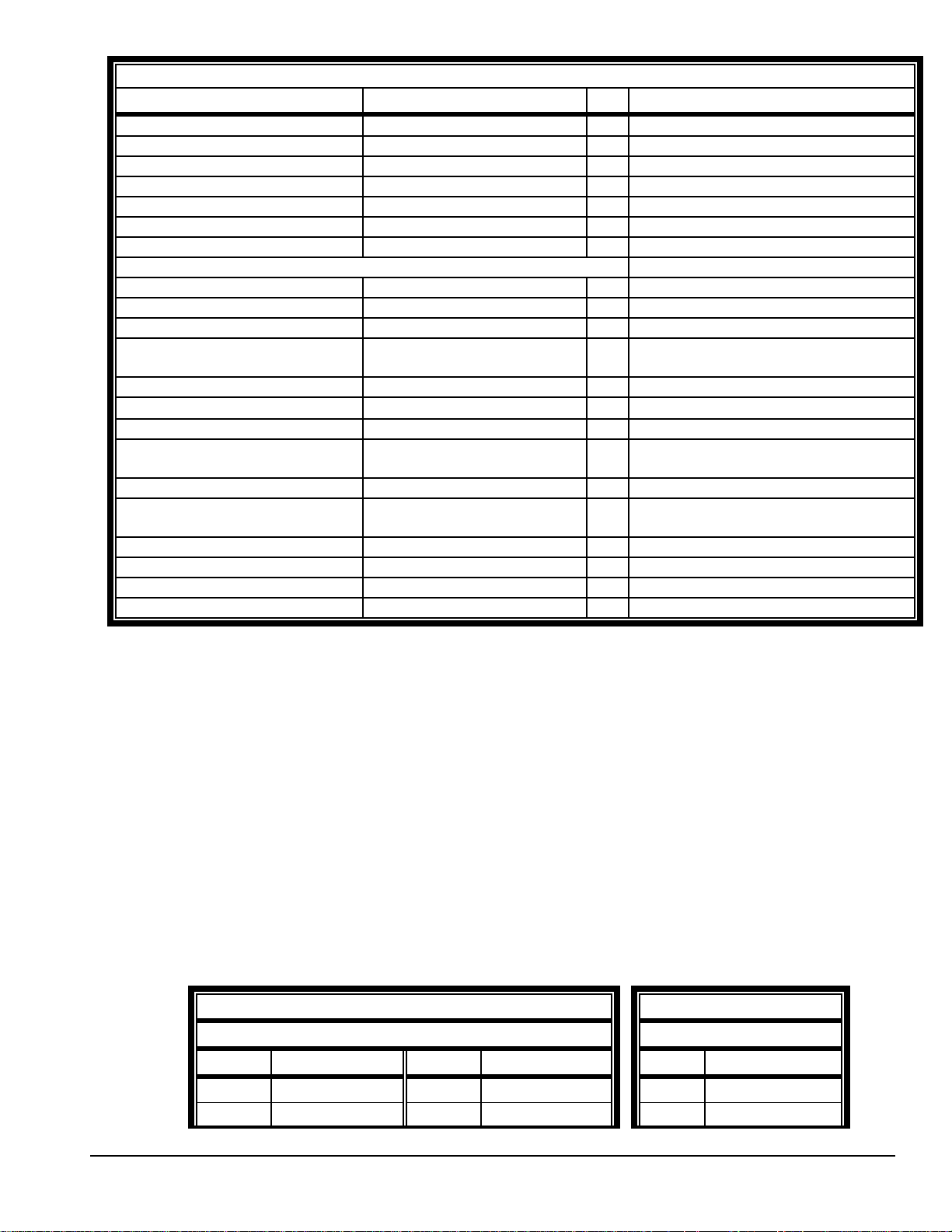
COMMAND CODE SUMMARY TABLE II
COMMAND RESPONSE D DESCRIPTION
TIR TIR {time/date} Time and Date setup recall.
PAE {p1} ACK Parrallel I/O setup entry.
PAR PAR {p1} Parrallel I/O setup recall.
ANE {anlg 1|---sp adj} ACK Analog setup entry.
ANR ANR { anlg 1|---sp adj } Analog setup recall.
TNE { } ACK Setpoint (Trip point) entry
TNR TNR { } Setpoint (Trip point) recall
TEMPERATURE CAL:
TPD ACK - Temperature Cal on.
TXD ACK - Temperature Cal off.
TRD ACK - Temperature Cal Reset.
TFR TFR {t data} 8 Temperature reading (current)
recall.
RZD ACK - Zero Temp Reference acquire.
RSD ACK - Span Temp Reference acquire.
HxD ACK - Zero Temp Hot acquire (x-1,2 or 3).
HxD ACK - Span Temp Hot acquire (x=X,Y or
Z).
CxD ACK - Zero Temp Cold acquire(x=1,2 or 3).
CxD ACK - Span Temp Cold acquire(x=X,Y or
Z).
DxE {---} ACK Temp. corrections entry (x=1 or 2).
DxR DxR {---} Temp. corrections recall (x=1 or 2).
TxR TxR {---} Temp. diag. data recall (x=1,2 or 3).
9.0 RECALLED DATA:
COMMANDS:
PDR = Display data.
PGR = Pressure data
PNR = Delta Pressure. ;later
PPR = Max data.
PMR = Min data.
RESPONSE DATA:
DATA FORMAT: <pr><unit1><unit2><par><stat>
LENGTH: fixed at 12 characters.
WHERE:
Unit 1 DESCRIPTION Unit 1 DESCRIPTION Unit 2 DESCRIPTION
A mmHgOΕCKKpa A ABSOLUTE
B BAR L Mbar G GAGE
pr: Eight (8) character data field for pressure including polarity and decimal point.
Has "space" for positive data and "minus" (-) for negative data.
Unit1 & 2:Two (2) characters (Refer to Table III and Table IV )
TABLE III TABLE IV
Pressure ‘unit 1’ Assignment Pressure ‘unit 2’
PAGE 8 74845
Page 9
C CmH2OMmmH2O4ΕCVVAC (SPECIAL)
D inHgOΕCNPASCAL
E Kg/cm
F FtseaH2OPPSI
G inH2O60F Q (SPARE)
H inH2O68F R (SPARE)
I inH2O4ΕCS(SPARE)
J MetrsH2OTTORR
par: one (1) character data field per Table V;
2
O (SPARE)
TABLE V
‘par’ ASSIGNMENT
<par> DESCRIPTION
‘sp’ Standard Pressure
N Net (pressure with Tare)
T Tare
HHP
P Max
M Min
F Freeze
stat: one (1) character data field;
10.0 STATUS RECALLED:
! COMMANDS:
PSR = Pressure status (motion, etc).
MSR = Unit/mode status
ISR = Input status.
OSR = Output status.
! Units/Mode status (MSR command)
DATA FORMAT: <unit1><unit2>|<mode>
LENGTH: Fixed at 4 characters.
WHERE:
Unit1&2: Two (2) character field. For character assignment refer to Table III &
Table IV.
par: One (1) character field. For character assignment refer to Table VI.
I= Invalid data O = Over range
U= Under range M = Motion
C= Center of zero 'Sp' = None of the above
TABLE VI
‘mode’ ASSIGNMENT
<mode> DESCRIPTION
N Standard
C Cal/config
PAGE 9 74845
Page 10
! Pressure status (PSR command)
DATA FORMAT: <stat>
LENGTH: Fixed at 1 character
WHERE:
stat: one character data field;
I = invalid data
O= over range
U= under range
M= motion
C = center of zero
'Sp' = none of the above
! Input status (ISR command):
DATA FORMAT: <i1>|<i2>
LENGTH: Fixed at 3 characters
WHERE:
i1 = input 1 status
i2 = input 2 status
0 represents an open input (logic 1)
1 represents a closed input (logic 0)
| = seperation character.
! Output status (OSR command):
DATA FORMAT: <o1>|<o2>
LENGTH: Fixed at 3 characters
WHERE:
o1 = output 1 status
o2 = output 2 status
0 represents an open output (logic 1)
1 represents a closed output (logic 0)
| = separation character.
T Temp
D Diagnostic ;later
11.0 CAPACITY/RESOLUTION ENTRY AND RECALL:
! COMMANDS:
CPE{} / CPR = Capacity.
REE{} / RER = Resolution.
! Capacity DATA entry (CPE{} command) and recall (CPR command):
DATA FORMAT: <data>
LENGTH: Fixed at 6 characters.
WHERE: data: Six (6) character data field with no polarity and decimal point.
-Entry with or without leading zero blanking.
-Recall with leading zero blanking.
! Resolution DATA entry (REE{} command) and recall (RER command):
DATA FORMAT: <data>
LENGTH: Fixed at 5 characters.
WHERE: data: Five (5) character data field including decimal point when required.
-On Entry and Recall, if a decimal point is included then use full
leading zeros; if no decimal point is included then begin data with
a space followed by leading zeros.
12.0 BASE UNITS ENTRY AND RECALL:
! COMMANDS:
UUE{}/UUR = BASE UNITS ENTRY AND RECALL
PAGE 10 74845
Page 11

! Cal Units DATA entry (UUE{} command) and recall ( UUR command)
FORMAT: <unit1><unit 2>
LENGTH: Fixed at two (2) characters.
WHERE:
13.0 CALIBRATION:
! General:
The unit must be set for Calibration (Mode Rocker switch 1 or 2 closed).
! COMMANDS:
ZCD = Perform Zero Cal
RxD = Perform Linear Reset at point x(x is # from 1 - 9 or letter ‘A’)
LxE{} = Perform Linear Cal at point x ( x is a # from 1 - 9 or the letter ‘A’).
ZFE{} / ZFR = Zero Cal correction.
LXE{} / LXR = Span Cal linear corr. All X's.
LFE{} / LFR = Span Cal linear corr. All S's.
LCE{} / LCR = Span Cal linear corr. All C's.
HCE{} = Perform Hysteresis cal.
HFE{} / HFR = Hysteresis correction.
! Calibration ‘Perform’ command data entry:
COMMANDS: LxE{}, HCE{}
DATA FORMAT: <data>
LENGTH: Fixed at 6 characters.
WHERE: data: Six (6) character data field with leading zeros and no
EXAMPLE: 10.00 PSI entered as {001000}
unit1 : Table III (P=PSI, etc.).
unit2 : Table IV (G=Gage,etc.).
decimal point.
! Calibration ‘Correction’ command data entry and recall:
♦ Zero Cal and Hysteresis correction data;
♦ Span Cal Linear corrections (all X’s,S’s, C’s) commands entry and recall data:
14.0 SETUP DATA:
14.1 GENERAL:
♦ FORMAT: <par 1>|<par 2>| - - - <par x>
♦ Setup data is set in a string using the separation character '|' between parameters.
♦ The parameters are listed in the order of the function diagram as they appear in the
♦ 'Arrow' select parameters are represented as a number starting with '0'.
♦ Numeric entered data is directly represented by its data value.
♦ When entering setup data, the full string of parameters need not be entered.
COMMANDS: ZFE{}/ZFR, HFE{}/HFR
DATA FORMAT: <x1>|<c1>
LENGTH: Fixed at 17 characters.
WHERE: x1, c1 = Eight (8) character data fields
each.
COMMANDS: LXE{}/LXR, LFE{}/LFR, LCE{}/LCR
DATA FORMAT: <x1><|><x2><|><x3><|><x4><|><x5><|><x6><|><x7><|>
<x8><|><x9><|><xA>
LENGTH: Fixed at 89characters.
WHERE: x1 - xA: Eight (8) character data field each.
manual.
14.2 COMMANDS:
SUE{}/ SUR = Main Pressure setup.
FLE{} / FLR = Filter setup.
P1E{} / P1R = Port 1 serial setup.
PAGE 11 74845
Page 12
P2E{} / P2R = Port 2 serial setup.
INE{} / INR = Input setup.
TME{} / TMR = Time.
DTE{} / DTR = Date.
TIE{} / TIR = Time/Date Setup
PAE{} / PAR = Parallel I/O setup
ANE{} / ANR = Analog setup.
14.3 PRESSURE:
COMMAND: SUE{}/SUR
DATA FORMAT: <d/s>|<ze%>|<z+%>|<azm>|<mot>|<ze set>|<min>
LENGTH: Fixed at 13 characters.
WHERE:
Note: The following parameters are not included:
d/s = Display per Second update rate fixed at 1 number code..
ze% = Zero Aperature % of FS ( Zero %) fixed at 1 number code.
z+% = Zero Band in % of FS (Zero+/-%) fixed at 1 number code.
azm = AZM Band in divisions (AZM +/-) fixed at 1 number code.
mot = Motion Band in divisions (Motion) fixed at 1 number code.
ze set = Auto Tare or Fixed Offset Zero Set) fixed at 1 number code.
min = Minimum Mode enable (Min) fixed at 1 number code.
max = Max Mode enable (Max) fixed at 1 number code
frez = Freeze mode select.
CODE#DSP/
SEC
0 AUT
120.5 0.05 0.5 1 Auto Tare ON
2310.1 13OffSet
3520.235
450.5 5 10
5 100 1 10 20
6 1.5 50
14.4 FILTER SETUP:
COMMAND: FLE/FLR
DATA FORMAT: <code>
LENGTH: Fixed at 2 characters.
WHERE:
code = Two (2) digit Filter code # from 00 to 20 per table below.
CODE# FILTR 1 CODE# FILTR 1 CODE# FILTR 1 CODE# FILTR 1 CODE# FILTR 1
CODE # / PARAMETER ASSIGNMENT
ZERO%ZERO
+/-%
OFF FULL OFF OFF OF F OFF
O
AZM+/- MOT
ION
ZERO
Set
MIN
CODE # / FILTER PARAMETER ASSIGNMENT (FILTR1)
00 1 05 6 10 12 15 25 20 50
01 2 06 7 11 14 16 30
PAGE 12 74845
Page 13
02 3 07 8 12 16 17 35
03 4 08 9 13 18 18 40
04 5 09 1014201945
EXAMPLE: A filter setting of 14 would be *FLE{11}<cr>
14.5 PORT 1 SERIAL SETUP:
Not supported at this time.
14.6 PORT 2 SERIAL SETUP:
COMMAND: P2E/P2R
DATA FORMAT: <mode>|<del>|<t&d>|<data>|<eol>|<sot>|<eot>
LENGTH: Fixed at 15 characters.
WHERE: (all codes fixed at one (1) number code; see code tables below)
mode = Format mode select.
del = Delay select.
t&d = Time and Date.
data = Data select.
eol = End of line terminator.
sol = Start of text character.
eot = End of text character.
CODE # PORT 2 PARAMETER ASSIGNMENT
CODE# MODE DELAY T & D DATA EOL SOT EOT
0 STD AUTO OF F DISP CR/LF STX NONE
1 MOD 1 SEC ON GTN CR NONE EOT
2 CUST 2 SEC ABOVE SOH ET X
33 SEC BELOW F F
44 SEC LF
55 SEC
14.7 INPUT SETUP:
COMMAND: INE/INR
DATA FORMAT: <I1>|<I2>
LENGTH: Fixed at 3 characters.
WHERE: (all codes fixed at one (1) number code; see code table below)
I1 = Input #1
I2 = Input #2
CODE # INPUT 1 and 2
PARAMETER ASSIGNMENT
CODE# MODE
0 OFF
1 Freeze
2 Zero
3 Tare
4 Print
PAGE 13 74845
Page 14
14.8 TIME/DATE SETUP:
COMMAND: TIE/TIR
DATA FORMAT: <t1>|<t2>|<t3>
LENGTH: Fixed at 5 characters.
WHERE: (all codes fixed at one (1) number code; see code table below)
t1 = 12 hour or 24 hour select.
t2 = Date format select.
t3 = Date number or letter select
TIME/DATE PARAMETER ASSIGNMENT
CODE# T1 T2 T3
0 24 HR MM/DD/YY NUMBER
1 12 HR DD/MM/YY LETTER
14.9 PARALLEL SETUP:
COMMAND: PAE/PAR
DATA FORMAT: <par>
LENGTH: Fixed at 1 character.
WHERE: par: code fixed at one (1) number code; see code table below
CODE # PARALLEL PARAMETER ASSIGNMENT
CODE# MODE
0 Parallel OFF
1 Parallel ON
14.10 ANALOG SETUP:
COMMAND: ANE{}/ANR
DATA FORMAT: <anlg 1>|<anlg 2>|<anlg 3>|<zero>|<fs>|<zr adj>|<sp adj>
LENGTH: Fixed at characters.
WHERE:
anlg 1 = Analog Option select.
anlg 2 = 10 or 5 volt output
anlg 3 = Select type of data for the analog output.
zero = Zero offset entry.
fs = Full scale entry.
zr adj = Zero adjust entry.
sp adj = Span adjust entry.
CODE # / PARAMETER ASSIGNMENT
CODE# anlg 1 anlg 2 angl 3 Zero fs zr adj sp adj
0 ANLG OFF 10
volts
1 ANLG ON 5 volts DELTA T
PRESSURE xxxxxxxxxxxxxxxxxxxxxxxx xxxxxxx
x
14.11 SETPOINT (TRIP POINT) SETUP:
COMMAND: TNE{}/TNR
DATA FORMAT: <trip>|<disp>|<recall>|<trip1>|<type1>|<tp1>|<tp1H>|<tp1L>|<h1H>|
<hy1H>|<h1L>|<hy1L>|<trip2>|<type2>|<tp2>|<tp2H>|<tp2L>|<h2H>|
<hy2H>|<h2L>|<hy2L>
LENGTH: Fixed at characters.
WHERE:
PAGE 14 74845
Page 15
trip = Setpoint (Trip Point) Option select.
disp = Display indication
recall = Trip point status.
TRIP 1 TRIP 2
trip1 trip2 = Trip point enable
type1 type2 = Trip point type
tp1 tp2 = Trip point polarity
tp1H tp2H = Trip point high value of eight (8) digits with leading zeros and no
decimal point.
tp1L tp2L = Trip point low value of eight (8) digits with leading zeros and no
decimal point.
h1H h2H = Trip point high hysteresis polarity
hy1H hy2H = Trip point high hysteresis value of six (6) digits with leading
zeros and no decimal point.
h1L h2L = Trip point low hysteresis polarity
hy1L hy2L = Trip point low hysteresis value of six (6) digits with leading
zeros and no decimal point.
CODE # / PARAMETER ASSIGNMENT 1 0f 2
COD
E#
0 OFF TRIP NONE OFF TRIP PT UNDER
1ONACCEPT VIEW O N BAND OVER
2 MODIFY
trip disp recall trip1 &
trip2
type1 &
type2
tp1 &
tp2
CODE # / PARAMETER ASSIGNMENT 2 0f 2
COD
E#
0 xxxxxxxxxxxxxxxxDESCEND xxxxxx DESCEND xxxxxx
1 ASCEND ASCEND
15.0 TEMPERATURE CALIBRATION:
! COMMANDS:
TPD = Temperature Cal on.
TXD = Temperature Cal off.
TRD = Temperature reset.
TFR = Temperature reading.
RZD = Zero Temp Reference acquire.
RSD = Zpan Temp Reference acquire..
HxD = Zero Temp Hot acquire (x=1,2 or 3).
HxD = Span Temp Hot acquire (x=X,Y or Z).
CxD = Zero Temp Cold acquire.
CxD = Span Temp Cold acquire.
DxE{}/DxR = Temperature corrections (x=1 or 2).
TxR = Temperature diagnostic data recall (x=1,2 or 3).
! TEMPERATURE READING RECALL:
COMMAND: TFR
DATA FORMAT: <t data>
LENGTH: Fixed at 8 characters
WHERE: <t data> = eight (8) character data field (temp data not in calibrated
tp1H &
tp2H
tp1L &
tp2L
standard units).
h1H &
h2H
hy1H &
hy2H
h1L &
h2L
hy1L &
hy2L
PAGE 15 74845
Page 16

! TEMPERATURE CORRECTIONS DATA ENTRY AND RECALL:
COMMANDS: D1E{}/D1R and D2E{}/D2R
DATA FORMAT (1): <zr>|<zl1>|<zl2>|<zl3>|<zh1>|<zh2>|<zh3>|<sr>|<sl1>|<sl2>|<sl3>|
<sh1>|<sh2>|<sh3>
DATA FORMAT (2): <tr>|<tl1>|<tl2>|<tl3>|<th1>|<th2>|<th3>|<fzl1>|<fzl2>|<fzl3>|<fsl1>|
<fsl2>|<fsl3>|<fzh1>|<fzh2>|<fzh3>|<fsh1>|<fsh2>|<fsh3>
DATA LENGTHS: Part (1)=Fixed at 126 characters
Part (2)=Fixed at 171 characters
WHERE (all parameters eight (8) characters in length):
zr = Zero Reference
zl1/2/3 = Zero low temperature a/d readings.
zh1/2/3 = Zero high temperature a/d readings.
sr = Span Reference
sl1/2/3 = Span low temperature a/d readings.
sh1/2/3 = Span high temperature a/d readings
tr = Reference temperature
tl1/2/3 = Low cal temperatures.
th1/2/3 = High cal temperatures.
fzl1/2/3 = Zero functions at low temperatures.
fsl1/2/3 = Span functons at low temperatures.
fzh1/2/3 = Zero functions at high temperatures.
fsh1/2/3 = Span functions at hight temperatures.
! TEMPERATURE DIAGNOSTICS DATA RECALL:
COMMANDS: T1R ,T2R and T3R
DATA FORMAT (1): <zc>|<sc>|<wa>|<ftl>|<ftl2>|<ftl3>|<fth>|<fth2>|<fth3>|<zr>|<zl1>|
<zl2>|<zl3>|<zh1>|<zh2>|<zh3>
DATA FORMAT (2): <sr>|<sl1>|<sl2>|<sl3>|<sh1>|<sh2>|<sh3>|<tr>|<tl1>|<tl2>|<tl3>|
<th1>|<th2>|<th3>
DATA FORMAT (3): <fzl1>|<fzl2>|<fzl3>|<fsl1>|<fsl2>|<fsl3>|<fzh1>|<fzh2>|<fzh3>|
<fsh1>|<fsh2>|<fsh3>
LENGTH: Part (1)= Fixed at 143 characters
Part (2)= Fixed at 125 characters
Part (3)= Fixed at 107 characters
WHERE (all parameters eight (8) characters in length):
zr = Zero Reference
zl1/2/3 = Zero low temperature a/d readings.
zh1/2/3 = Zero high temperature a/d readings.
sr = Span Reference
sl1/2/3 = Span low temperature a/d readings.
sh1/2/3 = Span high temperature a/d readings
tr = Reference temperature
tl1/2/3 = Low cal temperatures.
th1/2/3 = High cal temperatures.
fzl1/2/3 = Zero functions at low temperatures.
fsl1/2/3 = Span functons at low temperatures.
fzh1/2/3 = Zero functions at high temperatures.
fsh1/2/3 = Span functions at hight temperatures.
16.0 COMMAND CODE ALPHABETICAL (xxD=COMMAND, xxR=RECALL & XxE=ENTRY):
AxE / AxR = Fill Preact
CPE / CPR = Capacity.
CxD = Zero Temp Cold acquire (x=1,2 or 3).
CxD = Span Temp Cold acquire (x=X,Y or Z).
PAGE 16 74845
Page 17

DTE / DTR = Date.
DxE / DxR = Temperature Corrections entry and recall (x=1 or 2)
FLE / FLR = Filter setup.
HCD = Perform Hysteresis cal.
HFE/HFR = Hysteresis correction.
HNE/HNR = RPM/HP setup data.
HxD = Span Temp Hot Acquire.(x=X,Y or Z).
HxD = Zero Temp Hot Acquire (x=1,2 or 3).
INE / INR = Input setup.
ISR = Input status.
LCE / LCR = Span Cal Linear corr. All C's.
LFE / LFR = Span Cal Linear corr. All S's.
LxE = Perform Linear Cal at point x; Where x is a # from 1 - 9 or A
LXE / LXR = Span Cal Linear corr. All X's.
MGD = Display to pressure mode. ;later
MMD = Display to min mode. ;later
MND = Display to net mode. ;later
MPD = Display to max mode. ;later
MSR = Unit/mode status
OSR = Output status.
PAE/PAR = Parallel I/O setup.
PDR = Display data.
PGR = Pressure data.
PHR = HP data
PMR = Min data.
PNR = Applied tare. ;later
PPR = Max data.
PRD = Print to printer port 2.
PSR = Pressure status (motion, etc).
P2E / P2R = Port 2 serial setup.
REE / RER = Resolution.
RSD = Span temp reference acquire.
RxD = Linearization Reset (x = 1-9 or A)
RZD = Zero temp reference acquire.
SUE/SUR = Main Pressure setup.
TAD = Tare. / is function of motion etc. :later
TFR = Temperature reading.
TIE/TIR = Time and Date setup.
TME / TMR = Time.
TNE / TNR = Setpoint (Trip Point) setup
TPD = Temperature cal on.
TRD = Temperature reset.
TXD = Temperature cal off.
TxR = Temperature disgnostic recall (x=1,2 or 3)
UUE/UUR = Base ‘cal’ units config
UxD = Select units
ZCD = Perform Zero Cal.
ZED = Zero.
ZFE / ZFR = Zero cal correction.
PAGE 17 74845
 Loading...