


Comtrend AR5313U User Manual
75
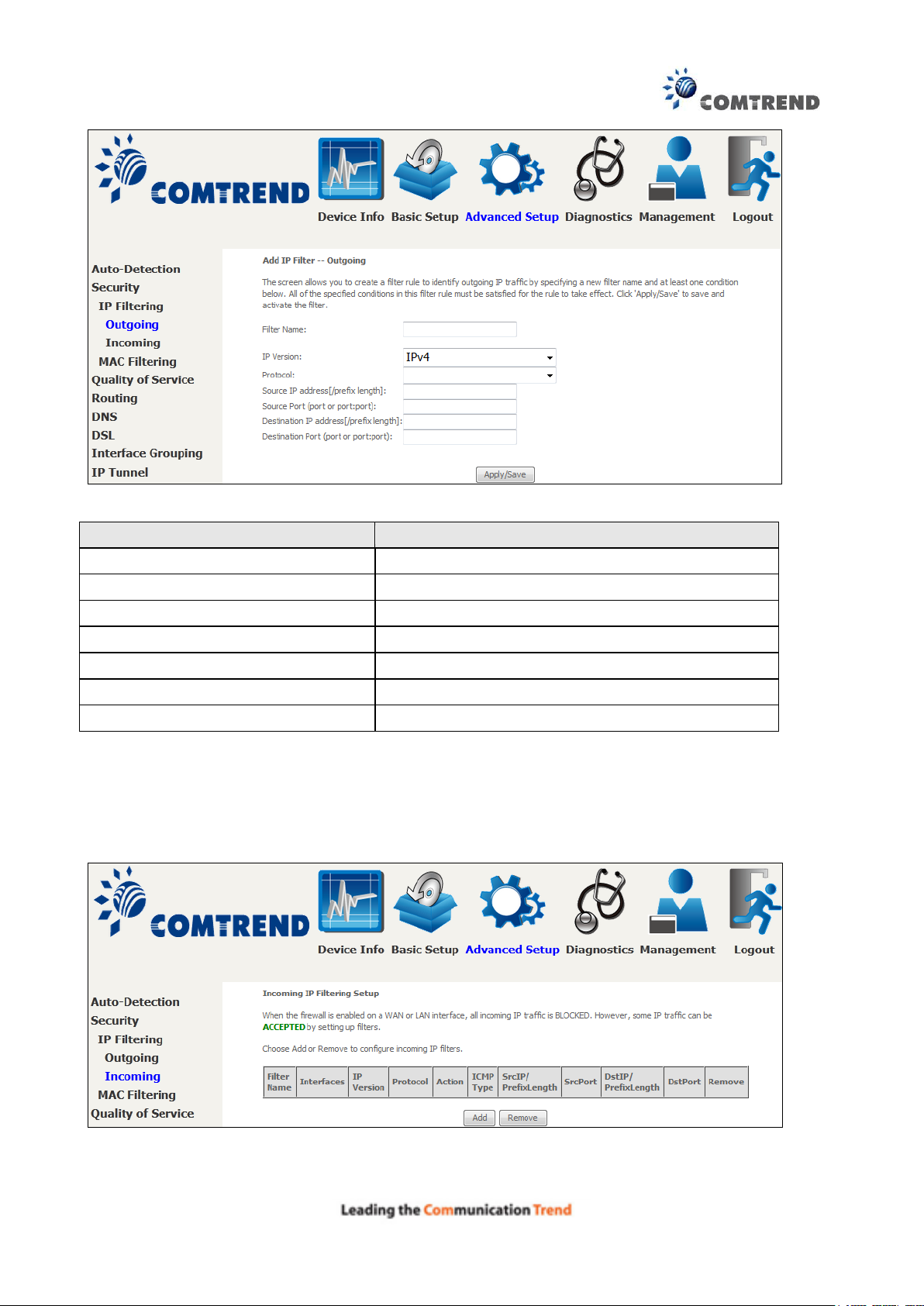
Field
Description
Filter Name
The filter rule label
IP Version
Select from the drop down menu.
Protocol
TCP, TCP/UDP, UDP, or ICMP.
Source IP address
Enter source IP address.
Source Port (port or port:port)
Enter source port number or range.
Destination IP address
Enter destination IP address.
Destination Port (port or port:port)
Enter destination port number or range.
Consult the table below for field descriptions.
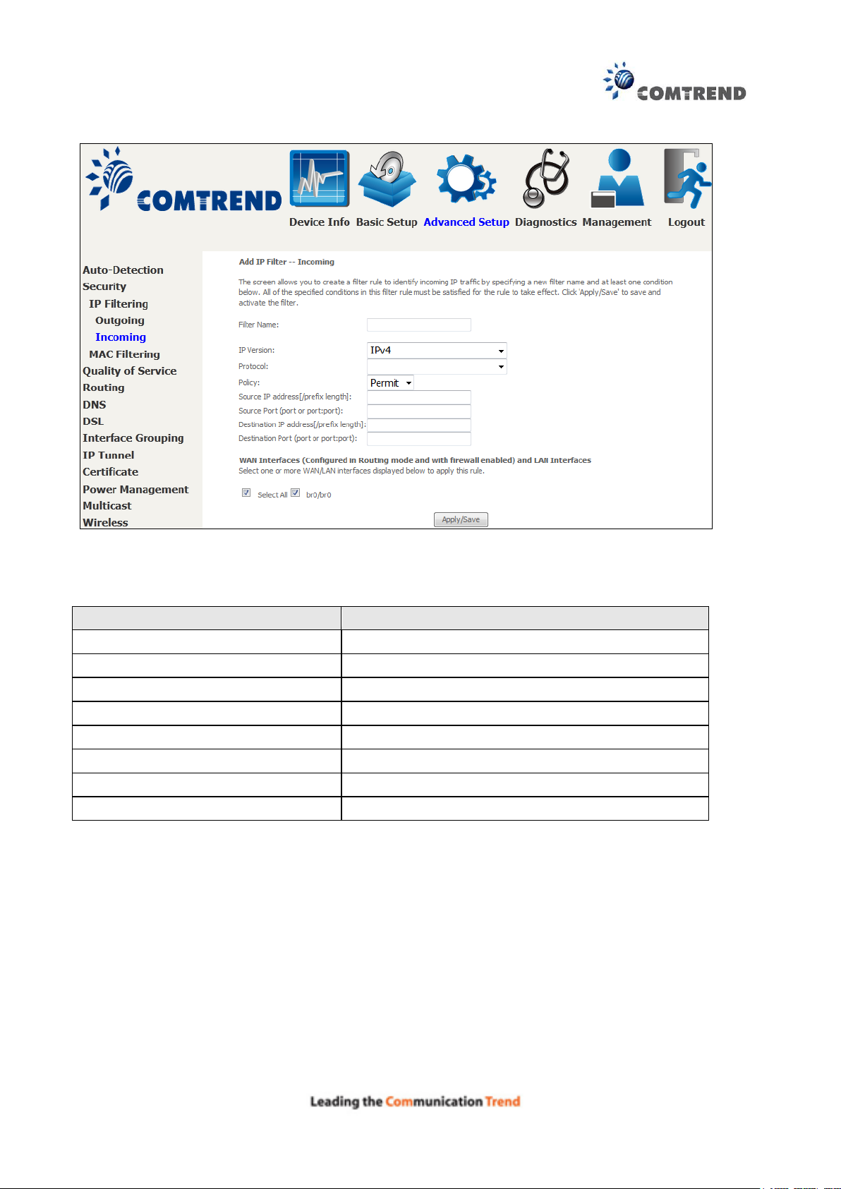
INCOMING IP FILTER
By default, all incoming IP traffic is blocked, but IP traffic can be allowed with filters.
To add a filter (to allow incoming IP traffic), click the Add button.
On the following screen, enter your filter criteria and then click Apply/Save.
76
Field
Description
Filter Name
The filter rule label.
IP Version
Select from the drop down menu.
Protocol
TCP, TCP/UDP, UDP, or ICMP.
Policy
Permit/Drop packets specified by the firewall rule.
Source IP address
Enter source IP address.
Source Port (port or port:port)
Enter source port number or range.
Destination IP address
Enter destination IP address.
Destination Port (port or port:port)
Enter destination port number or range.
Consult the table below for field descriptions.
At the bottom of this screen, select the WAN and LAN Interfaces to which the filter rule will apply.
You may select all or just a subset. WAN interfaces in bridge mode or without firewall enabled are
not available.
77
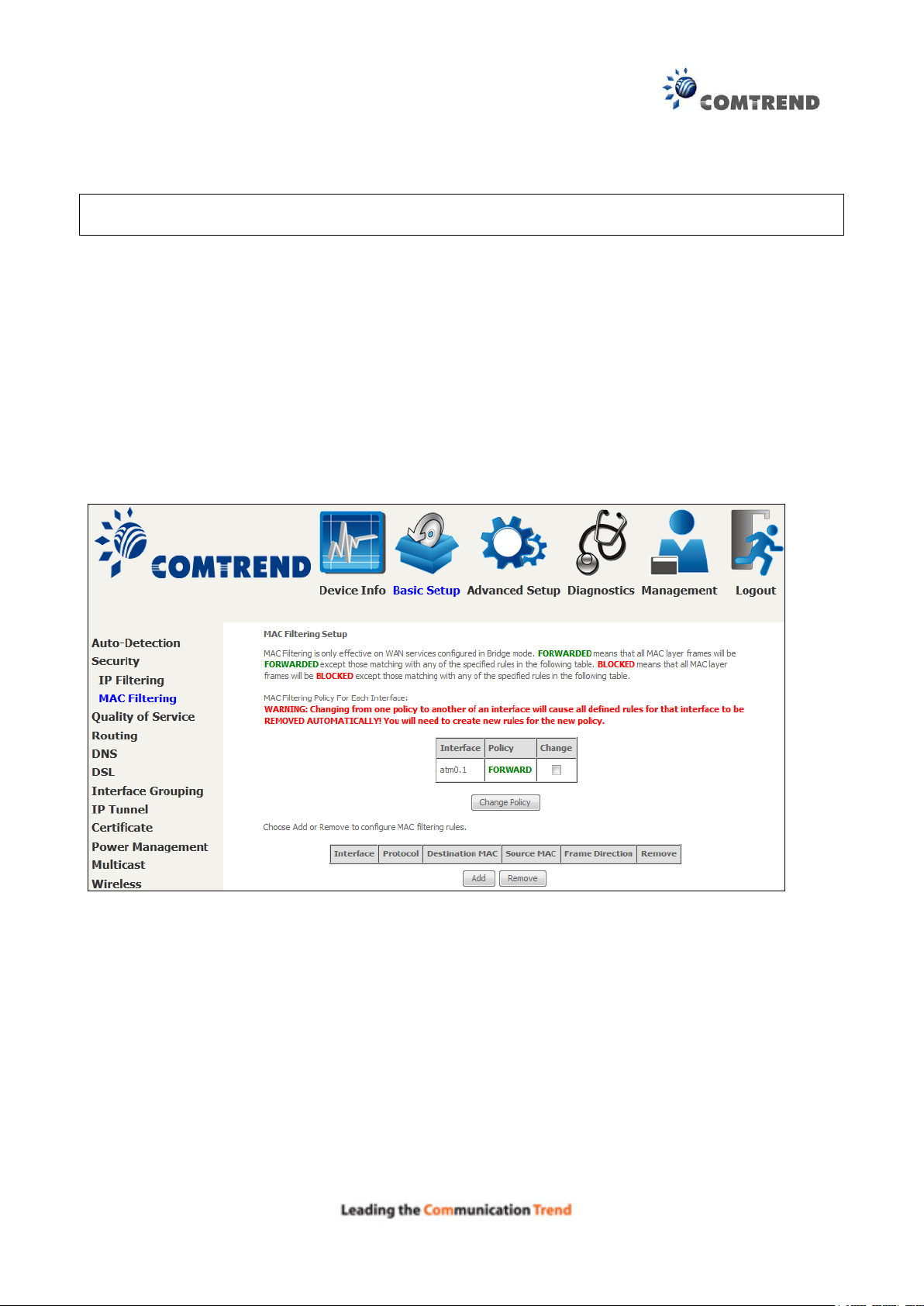
6.2.2 MAC Filtering
NOTE: This option is only available in bridge mode. Other modes use IP Filtering to perform a
similar function.
Each network device has a unique 48-bit MAC address. This can be used to filter (block or forward)
packets based on the originating device. MAC filtering policy and rules for the AR-5313u can be
set according to the following procedure.
The MAC Filtering Global Policy is defined as follows. FORWARDED means that all MAC layer
frames will be FORWARDED except those matching the MAC filter rules. BLOCKED means that
all MAC layer frames will be BLOCKED except those matching the MAC filter rules. The default
MAC Filtering Global policy is FORWARDED. It can be changed by clicking the Change Policy
button.
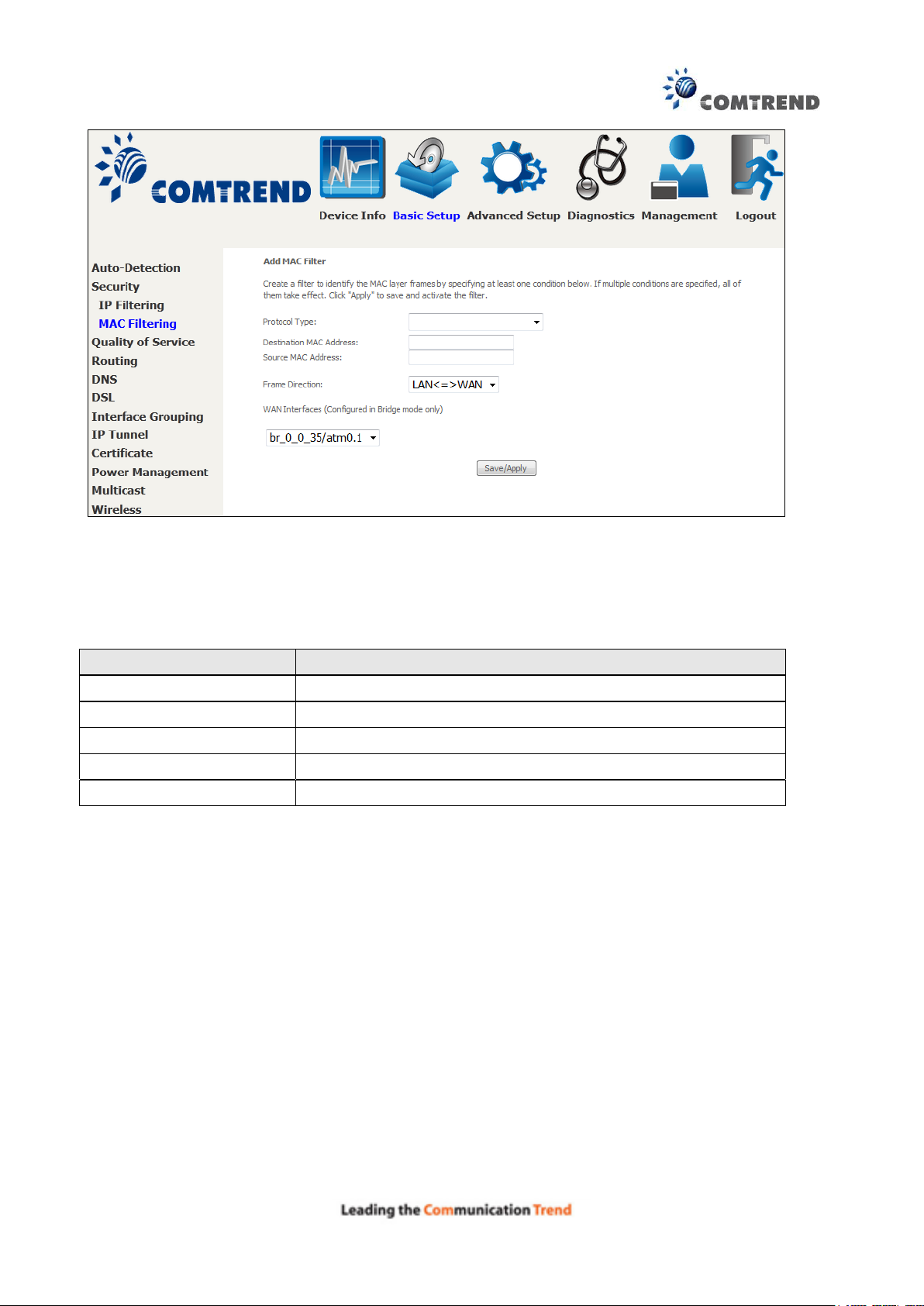
Choose Add or Remove to configure MAC filtering rules. The following screen will appear when
you click Add. Create a filter to identify the MAC layer frames by specifying at least one condition
below. If multiple conditions are specified, all of them must be met. Click Save/Apply to save
and activate the filter rule.
78
Field
Description
Protocol Type
PPPoE, IPv4, IPv6, AppleTalk, IPX, NetBEUI, IGMP
Destination MAC Address
Defines the destination MAC address
Source MAC Address
Defines the source MAC address
Frame Direction
Select the incoming/outgoing packet interface
WAN Interfaces
Applies the filter to the selected bridge interface
Click Save/Apply to save and activate the filter rule.
Consult the table below for detailed field descriptions.
79
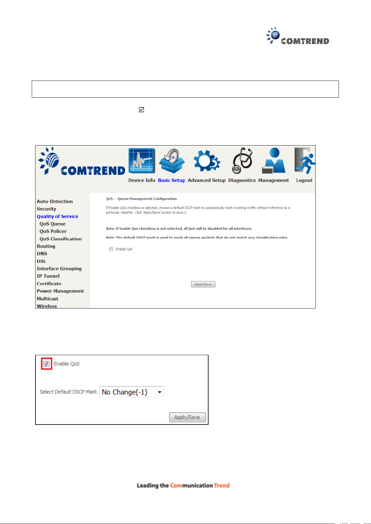
6.3 Quality of Service (QoS)
NOTE: QoS must be enabled in at least one PVC to display this option.
(See Appendix E - Connection Setup for detailed PVC setup instructions).
To Enable QoS tick the checkbox and select a Default DSCP Mark.
Click Apply/Save to activate QoS.
QoS and DSCP Mark are defined as follows:
Quality of Service (QoS): This provides different priority to different users or data flows, or
guarantees a certain level of performance to a data flow in accordance with requests from Queue
Prioritization.
Default Differentiated Services Code Point (DSCP) Mark: This specifies the per hop behavior for a
given flow of packets in the Internet Protocol (IP) header that do not match any other QoS rule.
80
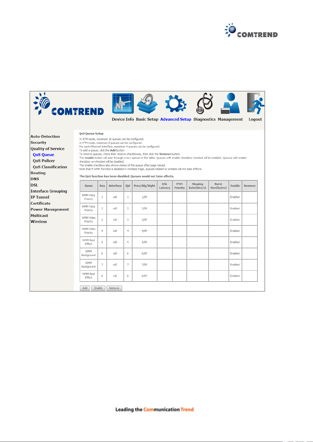
6.3.1 QoS Queue Setup
Configure queues with different priorities to be used for QoS setup.
In ATM mode, maximum 16 queues can be configured.
In PTM mode, maximum 8 queues can be configured.
For each Ethernet interface, maximum 4 queues can be configured.
To add a queue, click the Add button.
To remove queues, check their remove-checkboxes (for user created queues), then click the
Remove button.
The Enable button will scan through every queues in the table. Queues with enable-checkbox
checked will be enabled. Queues with enable-checkbox un-checked will be disabled.
The enable-checkbox also shows status of the queue after page reload.
Note that if WMM function is disabled in Wireless Page, queues related to wireless will not take
effect. This function follows the Differentiated Services rule of IP QoS. You can create a new
Queue entry by clicking the Add button.
Enable and assign an interface and precedence on the next screen. Click Save/Reboot on this
screen to activate it.
81
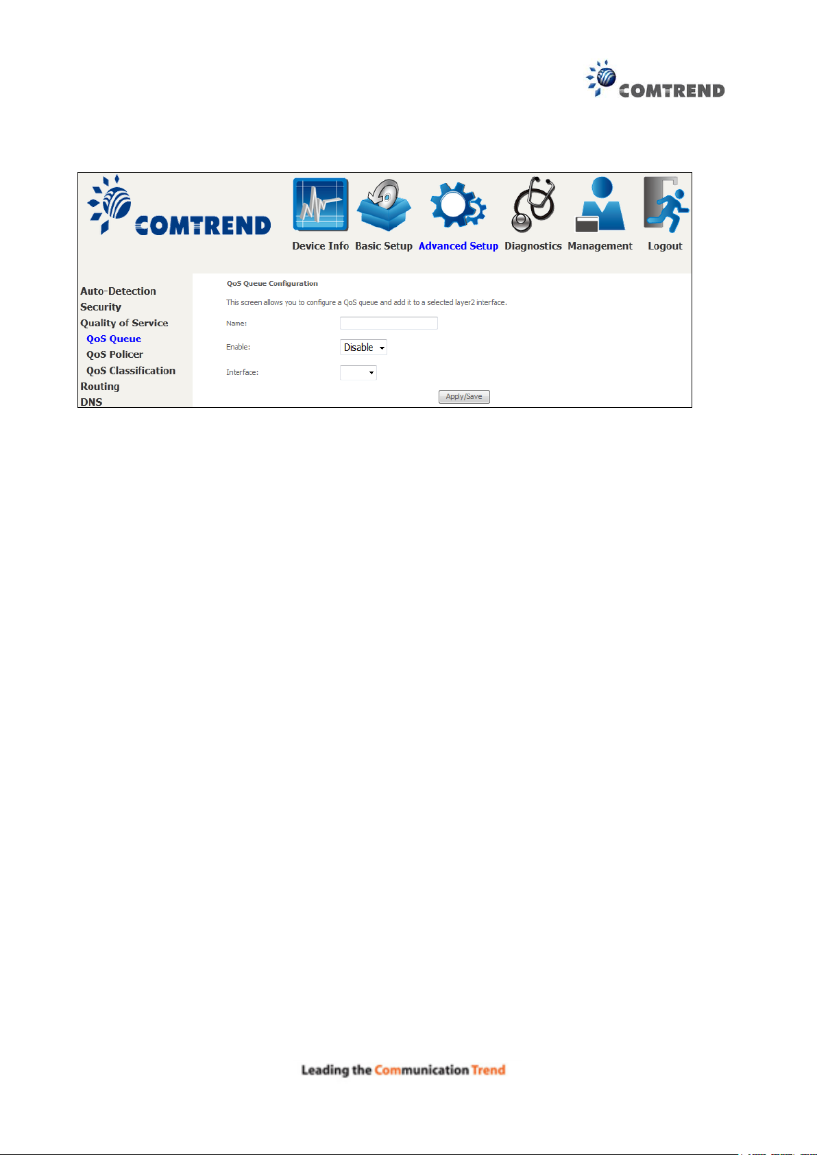
Click Add to display the following screen.
Click Apply/Save to apply and save the settings.
Name: Identifier for this Queue entry.
Enable: Enable/Disable the Queue entry.
Interface: Assign the entry to a specific network interface (QoS enabled).
82
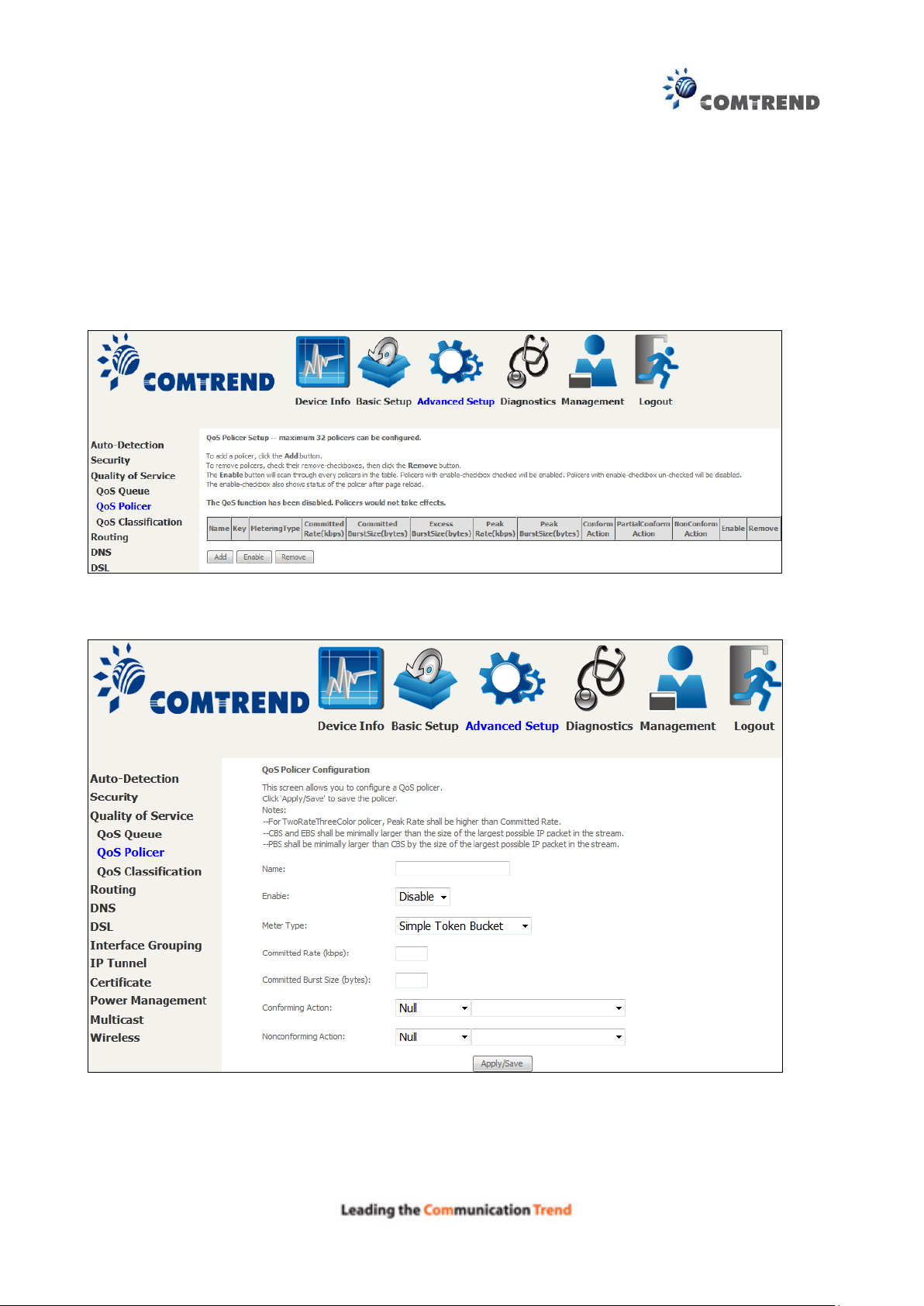
6.3.2 QoS Policer
To remove policers, check their remove-checkboxes, then click the Remove button.
The Enable button will scan through every policers in the table. Policers with enable-checkbox
checked will be enabled. Policers with enable-checkbox un-checked will be disabled.
The enable-checkbox also shows status of the policer after page reload.
To add a policer, click the Add button.
Click Apply/Save to save the policer.

83
Field
Description
Name
Name of this policer rule
Enable
Enable/Disable this policer rule
Meter Type
Meter type used for this policer rule
Committed Rate (kbps)
Defines the rate allowed for committed packets
Committed Burst Size
(bytes)
Maximum amount of packets that can be processed by this
policer
Conforming Action
Defines action to be taken if packets match this policer
Nonconforming Action
Defines actions to be taken if packets do not match this
policer
84
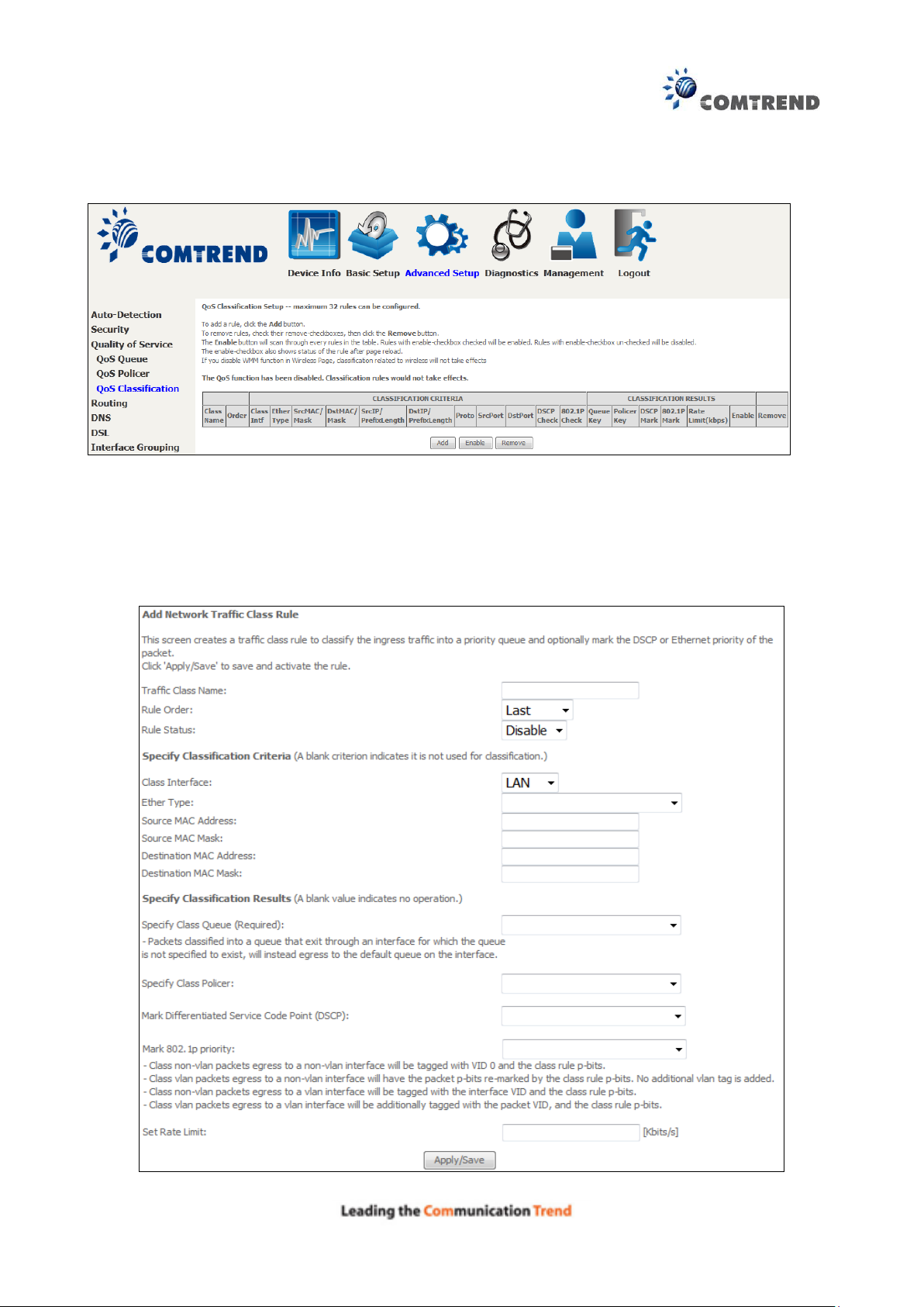
6.3.3 QoS Classification
The network traffic classes are listed in the following table.
Click Add to configure a network traffic class rule and Enable to activate it. To delete an entry
from the list, click Remove.
This screen creates a traffic class rule to classify the upstream traffic, assign queuing priority and
optionally overwrite the IP header DSCP byte. A rule consists of a class name and at least one
logical condition. All the conditions specified in the rule must be satisfied for it to take effect.

85
Field
Description
Traffic Class Name
Enter a name for the traffic class.
Rule Order
Last is the only option.
Rule Status
Disable or enable the rule.
Classification Criteria
Class Interface
Select an interface (i.e. Local, eth0-4, wl0)
Ether Type
Set the Ethernet type (e.g. IP, ARP, IPv6).
Source MAC Address
A packet belongs to SET-1, if a binary-AND of its source MAC
address with the Source MAC Mask is equal to the binary-AND of
the Source MAC Mask and this field.
Source MAC Mask
This is the mask used to decide how many bits are checked in
Source MAC Address.
Destination MAC Address
A packet belongs to SET-1 then the result that the Destination MAC
Address of its header binary-AND to the Destination MAC Mask
must equal to the result that this field binary-AND to the
Destination MAC Mask.
Destination MAC Mask
This is the mask used to decide how many bits are checked in
Destination MAC Address.
Classification Results
Specify Class Queue
Packets classified into a queue that exit through an interface for
which the queue is not specified to exist, will instead egress to the
default queue on the interface.
Specify Class Policer
Packets classified into a policer will be marked based on the
conforming action of the policer
Mark Differentiated
Service Code Point
The selected Code Point gives the corresponding priority to packets
that satisfy the rule.
Mark 802.1p Priority
Select between 0-7.
Set Rate Limit
The data transmission rate limit in kbps.
Click Apply/Save to save and activate the rule.
86
6.4 Routing
The following routing functions are accessed from this menu:
Default Gateway, Static Route, Policy Routing, RIP and IPv6 Static Route.
NOTE: In bridge mode, the RIP menu option is hidden while the other menu options are
shown but ineffective.
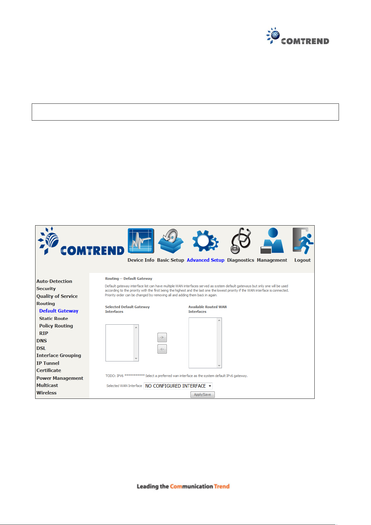
6.4.1 Default Gateway
Default gateway interface list can have multiple WAN interfaces served as system default
gateways but only one will be used according to the priority with the first being the highest and
the last one the lowest priority if the WAN interface is connected. Priority order can be changed by
removing all and adding them back in again.
87
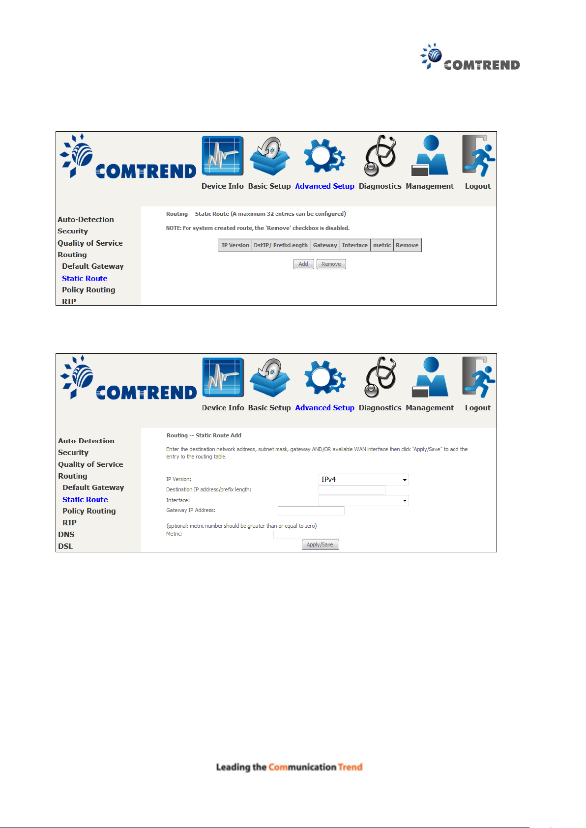
6.4.2 Static Route
This option allows for the configuration of static routes by destination IP.
Click Add to create a static route or click Remove to delete a static route.
After clicking Add the following will display.
IP Version: Select the IP version to be IPv4.
Destination IP address/prefix length: Enter the destination IP address.
Interface: select the proper interface for the rule.
Gateway IP Address: The next-hop IP address.
Metric: The metric value of routing.
After completing the settings, click Apply/Save to add the entry to the routing table.
88
Field
Description
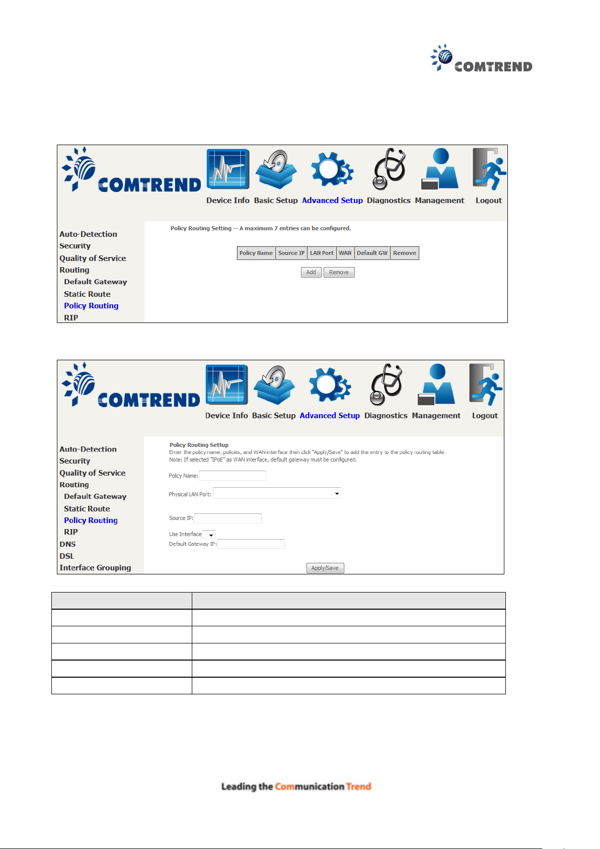
Policy Name
Name of the route policy
Physical LAN Port
Specify the port to use this route policy
Source IP
IP Address to be routed
Use Interface
Interface that traffic will be directed to
Default Gateway IP
IP Address of the default gateway
6.4.3 Policy Routing
This option allows for the configuration of static routes by policy.
Click Add to create a routing policy or Remove to delete one.
On the following screen, complete the form and click Apply/Save to create a policy.
89
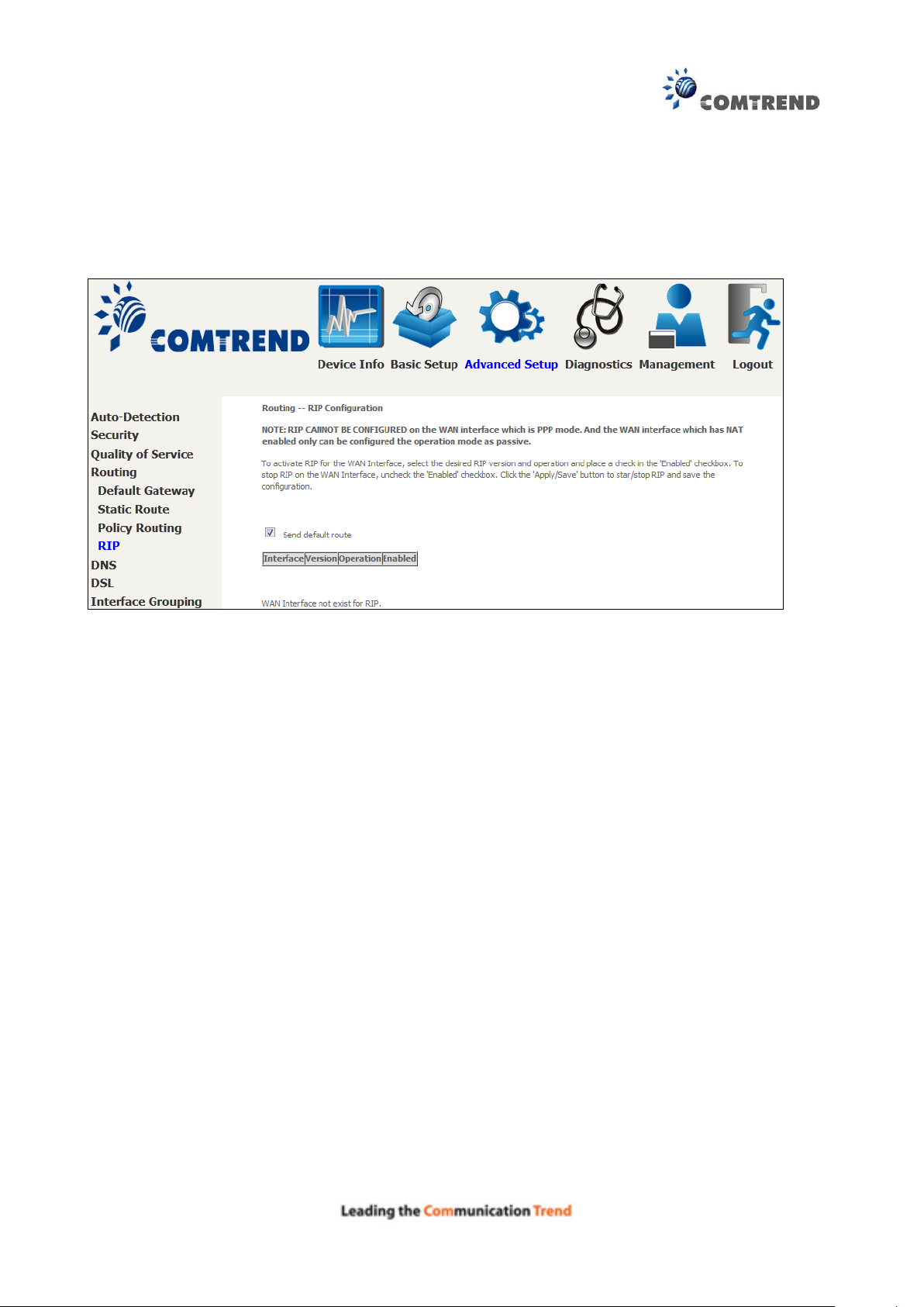
6.4.4 RIP
To activate RIP, configure the RIP version/operation mode and select the Enabled checkbox for
at least one WAN interface before clicking Save/Apply.
90
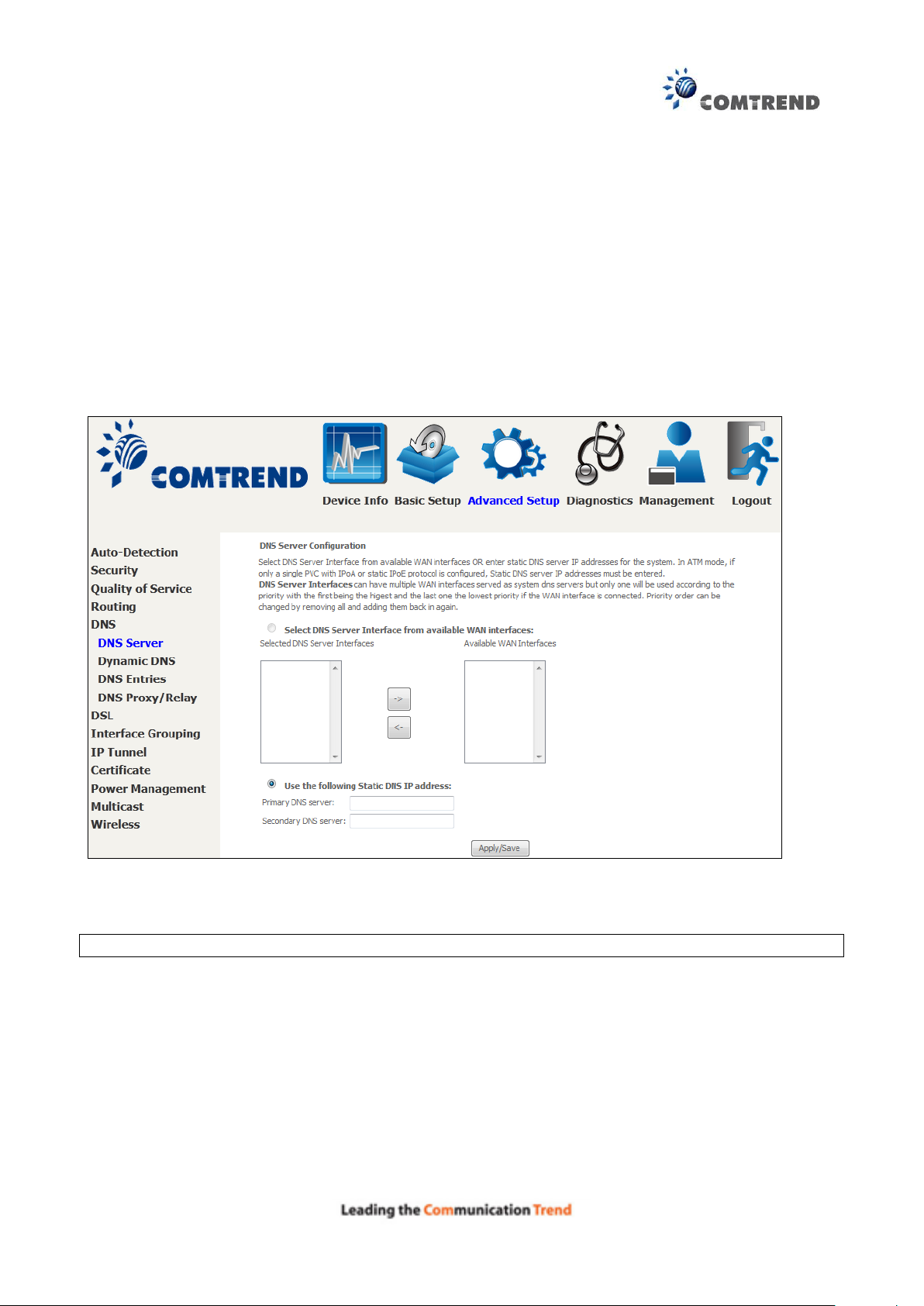
6.5 DNS
6.5.1 DNS Server
Select DNS Server Interface from available WAN interfaces OR enter static DNS server IP
addresses for the system. In ATM mode, if only a single PVC with IPoA or static IPoE protocol is
configured, Static DNS server IP addresses must be entered.
DNS Server Interfaces can have multiple WAN interfaces served as system dns servers but only
one will be used according to the priority with the first being the highest and the last one the
lowest priority if the WAN interface is connected. Priority order can be changed by removing all
and adding them back in again.
Click Apply/Save to save the new configuration.
NOTE: You must reboot the router to make the new configuration effective.
91
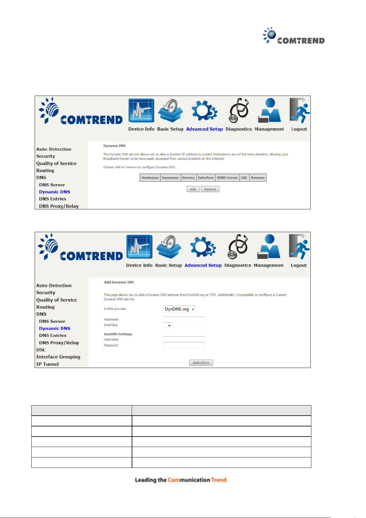
Field
Description
D-DNS provider
Select a dynamic DNS provider from the list
Hostname
Enter the name of the dynamic DNS server
Interface
Select the interface from the list
Username
Enter the username of the dynamic DNS server
Password
Enter the password of the dynamic DNS server
6.5.2 Dynamic DNS
The Dynamic DNS service allows you to map a dynamic IP address to a static hostname in any of
many domains, allowing the AR-5313u to be more easily accessed from various locations on the
Internet.
To add a dynamic DNS service, click Add. The following screen will display.
Click Apply/Save to save your settings.
Consult the table below for field descriptions.