

Comtrend 5374 Users Manual
CT-5374
Multi-DSL WLAN Router
User Manual
Version A2.1, April 30, 2010
261099-005

Preface
This manual provides information related to the installation and operation of this
device. The individual reading this manual is presumed to have a basic
understanding of telecommunications terminology and concepts.
If you find the product to be inoperable or malfunctioning, please contact technical
support for immediate service by email at
INT-support@comtrend.com
For product update, new product release, manual revision, or software upgrades,
please visit our website at
http://www.comtrend.com
Important Safety Instructions
With reference to unpacking, installation, use, and maintenance of your electronic
device, the following basic guidelines are recommended:
• Do not use or install this product near water, to avoid fire or shock hazard. For
example, near a bathtub, kitchen sink or laundry tub, or near a swimming pool.
Also, do not expose the equipment to rain or damp areas (e.g. a wet basement).
• Do not connect the power supply cord on elevated surfaces. Allow it to lie freely.
There should be no obstructions in its path and no heavy items should be placed
on the cord. In addition, do not walk on, step on, or mistreat the cord.
• Use only the power cord and adapter that are shipped with this device.
• To safeguard the equipment against overheating, make sure that all openings in
the unit that offer exposure to air are not blocked.
• Avoid using a telephone (other than a cordless type) during an electrical storm.
There may be a remote risk of electric shock from lightening. Also, do not use
the telephone to report a gas leak in the vicinity of the leak.
• Never install telephone wiring during stormy weather conditions.
CAUTION:
To reduce the risk of fire, use only No. 26 AWG or larger
telecommunication line cord.
Always disconnect all telephone lines from the wall outlet before servicing
or disassembling this equipment.
WARNING
Disconnect the power line from the device before servicing.
Power supply specifications are clearly stated in Appendix C -
Specifications
.
Copyright
Copyright©2010 Comtrend Corporation. All rights reserved. The information
contained herein is proprietary to Comtrend Corporation. No part of this document
may be translated, transcribed, reproduced, in any form, or by any means without
prior written consent of Comtrend Corporation.
1

NOTE: This document is subject to change without notice.
Protect Our Environment
This symbol indicates that when the equipment has reached the end of
its useful life, it must be taken to a recycling centre and processed
separate from domestic waste.
The cardboard box, the plastic contained in the packaging, and the parts that make
up this router can be recycled in accordance with regionally established regulations.
Never dispose of this electronic equipment along with your household waste; you
may be subject to penalties or sanctions under the law. Instead, please be
responsible and ask for disposal instructions from your local government.
FCC Compliance
This equipment has been tested and found to comply with the limits for a Class B
Digital Device, pursuant to part 15 of the FCC Rules. These limits are designed to
provide reasonable protection against harmful interference in a residential
installation. This equipment generates, uses and can radiate radio frequency energy
and, if not installed and used in accordance with the instruction, may cause harmful
interference to radio communication. However, there is no grantee that interference
will not occur in a particular installation. If this equipment dose cause harmful
interference to radio or television reception, which can be determined by turning the
equipment off and on , the user is encouraged to try to correct the interference by
one or more of the following measures:
Reorient or relocate the receiving antenna.
Increase the separation between the equipment and receiver.
Connect the equipment into an outlet on a circuit different from that to which
the receiver is connected.
Consult the dealer or an experienced radio/TV technician for help.
The changes or modifications not expressly approved by the party responsible for
compliance could void the user's authority to operate the equipment.
To comply with the FCC RF exposure compliance requirements, this device and its
antenna must not be co-located or operating to conjunction with any other antenna
or transmitter.
This equipment should be installed and operated with minimum distance 20cm
between the radiator & your body.
2

Table of Contents
CHAPTER 1 INTRODUCTION .......................................................................................................... 5
1.1 F
EATURES
1.2 A
PPLICATION
CHAPTER 2 INSTALLATION ............................................................................................................ 7
2.1 H
ARDWARE SETUP
2.2 LED I
CHAPTER 3 WEB USER INTERFACE ............................................................................................11
3.1 D
EFAULT SETTINGS
3.2 IP C
3.3 L
OGIN PROCEDURE
CHAPTER 4 DEVICE INFORMATION .......................................................................................... 16
4.1 WAN............................................................................................................................................. 17
4.2 S
TATISTICS
4.2.1 LAN Statistics................................................................................................................. 18
4.2.2 WAN Statistics ................................................................................................................ 18
4.2.3 ATM Statistics ................................................................................................................ 19
4.2.4 xDSL Statistics ............................................................................................................... 21
4.3 R
OUTE
4.4 ARP.............................................................................................................................................. 28
4.5 DHCP........................................................................................................................................... 29
CHAPTER 5 ADVANCED SETUP .................................................................................................... 30
5.1 L
AYER 2 INTERFACE
5.1.1 ATM Interface ................................................................................................................ 30
5.1.2 PTM Interface ................................................................................................................ 31
5.1.3 ETH WAN INTERFACE ................................................................................................. 31
5.2 WAN............................................................................................................................................. 32
5.3 LAN ............................................................................................................................................. 33
5.4 IPV6 LAN H
5.5 NAT.............................................................................................................................................. 36
5.5.1 Virtual Servers................................................................................................................ 36
5.5.2 Port Triggering .............................................................................................................. 38
5.5.3 DMZ Host....................................................................................................................... 39
5.6 S
ECURITY
5.6.1 IP Filtering..................................................................................................................... 40
5.6.2 MAC Filtering ................................................................................................................ 42
5.7 P
ARENTAL CONTROL
5.7.1 Time Restriction ............................................................................................................. 44
5.7.2 URL Filter...................................................................................................................... 45
5.8 Q
UALITY OF SERVICE (QO
5.8.1 Queue Management Configuration................................................................................ 46
5.8.2 Queue Configuration...................................................................................................... 46
5.8.3 QoS Classification.......................................................................................................... 47
5.9 R
OUTING
5.9.1 Default Gateway ............................................................................................................ 50
5.9.2 Static Route .................................................................................................................... 50
5.9.3 Policy Routing................................................................................................................ 51
5.9.4 RIP ................................................................................................................................. 52
5.9.5 IPv6 Static Route............................................................................................................ 53
5.10 DNS............................................................................................................................................ 54
5.10.1 DNS Server..................................................................................................................... 54
5.10.2 Dynamic DNS................................................................................................................. 54
5.11 DSL ............................................................................................................................................ 56
5.12 UPNP.......................................................................................................................................... 58
5.13 P
RINT SERVER
5.14 I
NTERFACE GROUPING
....................................................................................................................................... 5
................................................................................................................................... 6
.......................................................................................................................... 7
NDICATORS
ONFIGURATION
.......................................................................................................................................... 27
...................................................................................................................................... 40
....................................................................................................................................... 49
............................................................................................................................ 9
........................................................................................................................11
........................................................................................................................11
....................................................................................................................... 14
.................................................................................................................................... 17
...................................................................................................................... 30
OST
........................................................................................................................... 35
..................................................................................................................... 44
S) ......................................................................................................... 46
............................................................................................................................. 59
................................................................................................................ 59
3

5.15 C
ERTIFICATE
5.15.1 Local .............................................................................................................................. 62
5.15.2 Trusted CA ..................................................................................................................... 63
5.16 P
OWER MANAGEMENT
............................................................................................................................... 61
................................................................................................................ 65
CHAPTER 6 WIRELESS ................................................................................................................... 66
6.1 B
ASIC
............................................................................................................................................ 66
6.2 S
ECURITY
6.2.1 WPS....................................................................................................................................... 70
6.3 MAC F
6.4 W
IRELESS BRIDGE
6.5 A
DVANCED
6.6 S
TATION INFO
CHAPTER 7 DIAGNOSTICS ............................................................................................................ 81
CHAPTER 8 MANAGEMENT.......................................................................................................... 82
8.1 S
ETTINGS
8.1.1 Backup Settings .............................................................................................................. 82
8.1.2 Update Settings .............................................................................................................. 82
8.1.3 Restore Default............................................................................................................... 83
8.2 S
YSTEM LOG
8.3 SNMP A
8.4 TR-069 C
8.5 I
NTERNET TIME
8.6 A
CCESS CONTROL
8.6.1 Passwords ...................................................................................................................... 89
8.7 U
PDATE SOFTWARE
8.8 R
EBOOT
APPENDIX A - FIREWALL ............................................................................................................... 91
APPENDIX B - PIN ASSIGNMENTS ............................................................................................... 94
...................................................................................................................................... 68
ILTER
................................................................................................................................. 75
........................................................................................................................ 76
.................................................................................................................................... 77
................................................................................................................................ 79
...................................................................................................................................... 82
................................................................................................................................. 84
GENT
............................................................................................................................... 86
LIENT
............................................................................................................................. 87
............................................................................................................................. 88
......................................................................................................................... 89
....................................................................................................................... 89
........................................................................................................................................ 90
APPENDIX C - SPECIFICATIONS .................................................................................................. 95
APPENDIX D - SSH CLIENT ............................................................................................................ 98
APPENDIX E - WSC EXTERNAL REGISTRAR ........................................................................... 99
APPENDIX F - PRINTER SERVER ............................................................................................... 103
APPENDIX G - CONNECTION SETUP ........................................................................................ 109
4

Chapter 1 Introduction
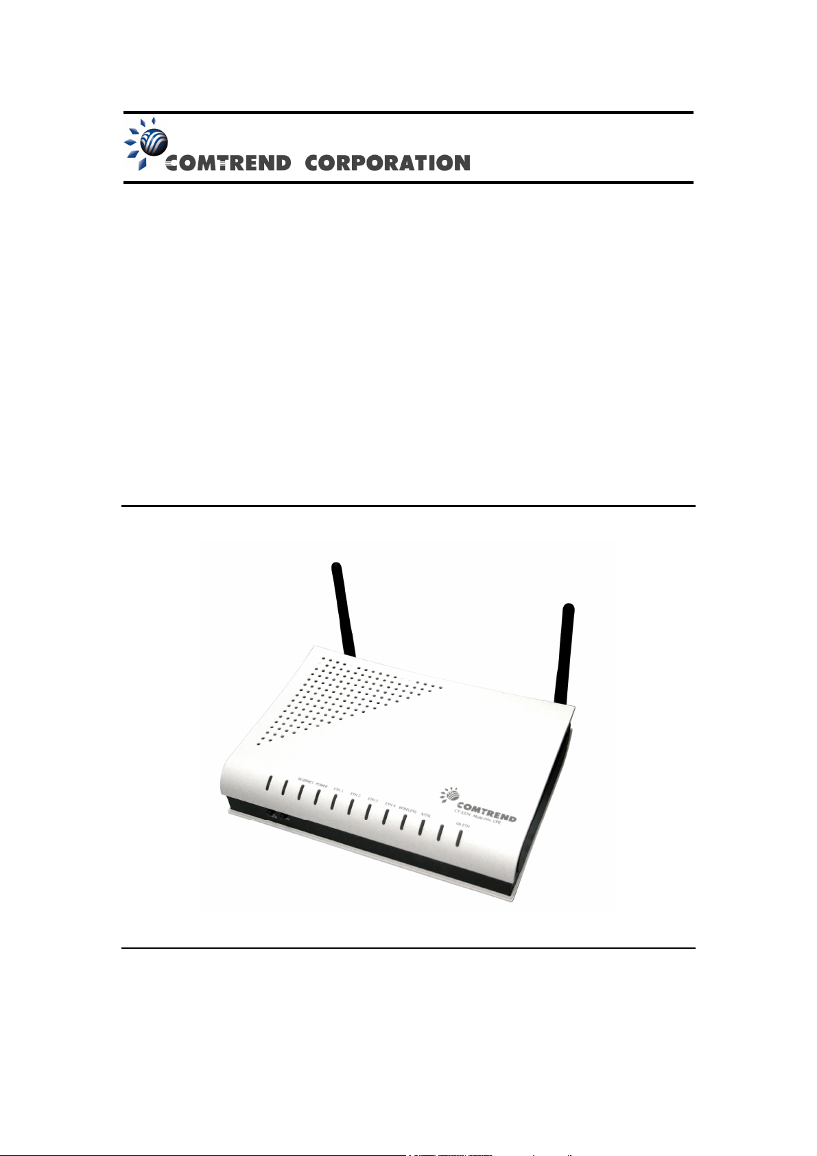
The CT-5374 Multi-DSL WLAN Router provides wired and wireless access for
high-bandwidth applications in the home or office. It includes four fast Ethernet
ports and supports ADSL2/2+ and VDSL2 connections
ADSL2+ connections support multiple simultaneous Internet connections while
VDSL2 connections are suitable for triple play (Video + Voice + Data) applications.
An integrated 802.11n (draft) WLAN Access Point (AP) provides faster wireless
connections with increased range, when compared with 802.11b and 802.11g,
without sacrificing backwards compatibility with these older wireless standards.
WPS (Wi-Fi Protected Setup) and Wi-Fi On/Off buttons are positioned on the front
panel for easy wireless network setup and control.
1.1 Features
with DSLAM switching.
• Integrated 802.11n AP
(802.11b/g backward-compatible)
• VDSL2 17a profile support • Auto PVC configuration
• IP and Per-VC packet level QoS • Supports up to 16 VCs
• WPA/WPA2 and 802.1x • WMM & UPnP
• RADIUS client • IP/MAC filtering
• Static routing & RIP/RIP v2 • Dynamic IP assignment
• NAT/PAT • Parental Control
• IGMP Proxy and fast leave • DHCP Server/Relay/Client
• Web-based management • DNS Relay/Proxy
• Supports remote administration • FTP/TFTP server
• Configuration backup and restoration
• Firmware upgrade and configuration
• Automatic ADSL2+ / VDSL2
switching based on DSLAM setting
• TR-069/TR-098/TR-104/TR-111
5
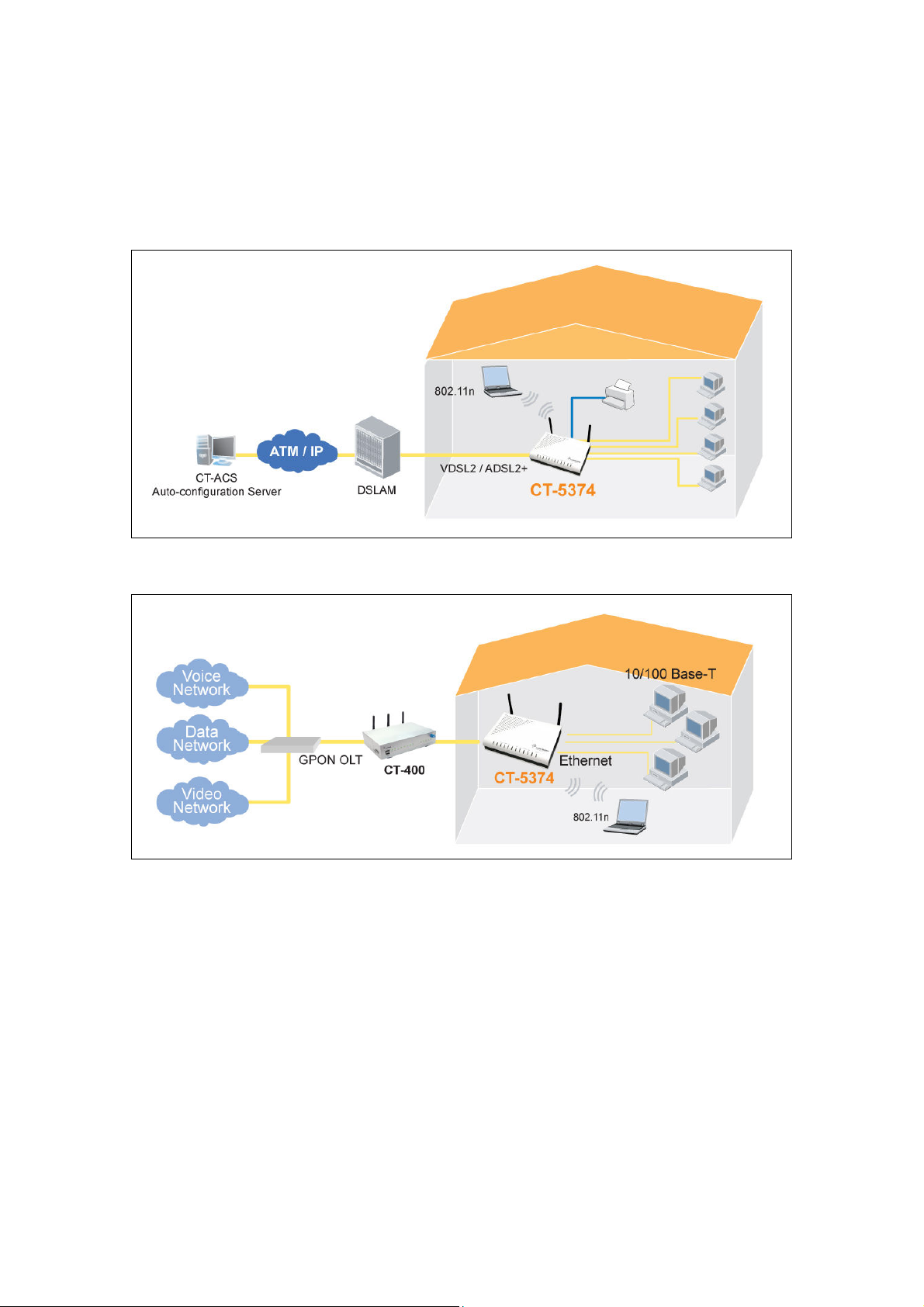
1.2 Application
The following diagrams depict typical applications of the CT-5374.
6
Chapter 2 Installation
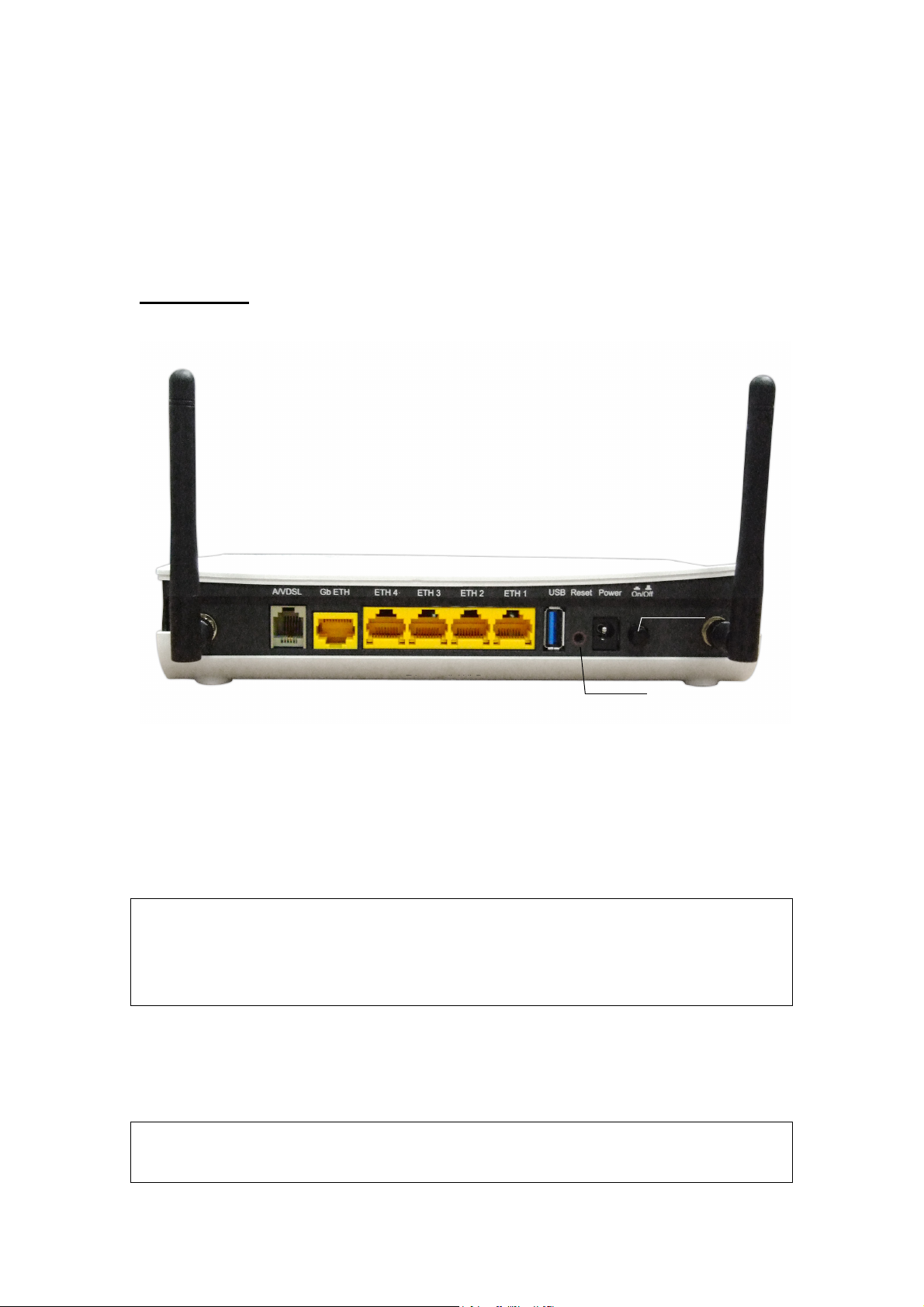
Reset Button
Ethernet (LAN) Ports
2.1 Hardware Setup
Follow the instructions below to complete the hardware setup.
BACK PANEL
The figure below shows the back panel of the device.
A/VDSL Port
Power Button
Power Port
Power ON
Press the power button to the OFF position (OUT). Connect the power adapter to the
power port. Attach the power adapter to a wall outlet or other AC source. Press the
power button to the ON position (IN). If the Power LED displays as expected then
the device is ready for setup (see section
2.2 LED Indicators).
Caution 1: If the device fails to power up, or it malfunctions, first verify that the
power cords are connected securely and then power it on again. If the
problem persists, contact technical support.
Caution 2: Before servicing or disassembling this equipment, disconnect all power
cords and telephone lines from their outlets.
Reset Button
Restore the default parameters of the device by pressing the Reset button for 5 to
10 seconds. After the device has rebooted successfully, the front panel should
display as expected (see section
2.2 LED Indicators for details).
NOTE: If pressed down for more than 20 seconds, the CT-5374 will go into a
firmware update state (CFE boot mode). The firmware can then be
updated using an Internet browser pointed to the default IP address.
7

Ethernet (LAN) Ports
Use 10/100 BASE-T RJ-45 cables to connect up to four network devices. These ports
are auto-sensing MDI/X; so either straight-through or crossover cable can be used.
DSL Port
Connect to an ADSL2/2+ or VDSL with this RJ11 Port. This device contains a micro
filter which removes the analog phone signal. If you wish, you can connect a
regular telephone to the same line by using a POTS splitter.
FRONT PANEL
The Wi-Fi & WPS buttons are located on the bottom-left of the front panel, as shown.
WiFi Switch
Press this button to enable/disable the wireless LAN (WLAN).
WPS Button
Press this button to begin searching for WPS clients. These clients must also enable
WPS push button mode (see 6.2.1 WPS for instructions).
8
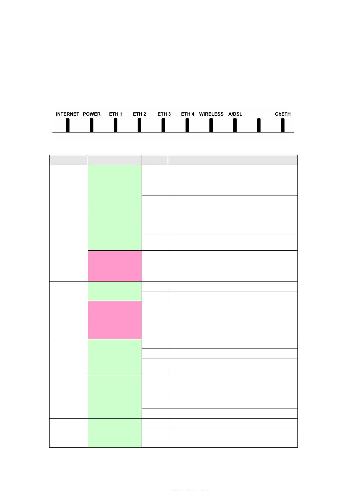
2.2 LED Indicators
The front panel LED indicators are shown below and explained in the following table.
This information can be used to check the status of the device and its connections.
LED Color Mode Function
On IP connected and no traffic detected. If
an IP or PPPoE session is dropped due to
an idle timeout, the light will remain green
if an ADSL connection is still present.
Green
INTERNET
Green
POWER
ETH 1X-4X
WIRELESS
A/DSL Green
Green
Green
Red On
Red On
Off Modem power off, modem in bridged mode
or ADSL connection not present. In
addition, if an IP or PPPoE session is
dropped for any reason, other than an idle
timeout, the light is turned off.
Blink IP connected and IP Traffic is passing thru
the device (either direction)
Device attempted to become IP connected
and failed (no DHCP response, no PPPoE
response, PPPoE authentication failed, no
IP address from IPCP, etc.)
On The device is powered up.
Off The device is powered down.
POST (Power On Self Test) failure or other
malfunction. A malfunction is any error of
internal sequence or state that will prevent
the device from connecting to the DSLAM
or passing customer data.
On An Ethernet Link is established.
Off An Ethernet Link is not established.
Blink Data transmitting or receiving over
Ethernet.
On The wireless module is ready.
(i.e. installed and enabled).
Off
Blink Data transmitting or receiving over WLAN.
On xDSL Link is established.
Off xDSL Link is not established.
Blink fast: xDSL Link is training or data
The wireless module is not ready.
(i.e. either not installed or disabled).
9

Green
GbETH
(for 10/100
Base-T)
Amber
(for 10/100/1000
Base-T)
transmitting.
slow: xDSL training failed.
On Powered device connected to the
associated port.
Off No activity, modem powered off, no cable
or no powered device connected to the
associated port.
Blink Traffic is passing.
On
Powered device connected to the
associated port.
No activity, modem powered off, no cable
Off
or no powered device connected to the
associated port.
Blink Traffic is passing.
10

Chapter 3 Web User Interface
This section describes how to access the device via the web user interface (WUI)
using an Internet browser such as Internet Explorer (version 5.0 and later).
3.1 Default Settings
The factory default settings of this device are summarized below.
• LAN IP address: 192.168.1.1
• LAN subnet mask: 255.255.255.0
• Administrative access (username: root , password: 12345)
• User access (username: user, password: user)
• Remote (WAN) access (username: support, password: support)
• WLAN access:
enabled
Technical Note
During power on, the device initializes all settings to default values. It will then
read the configuration profile from the permanent storage section of flash memory.
The default attributes are overwritten when identical attributes with different values
are configured. The configuration profile in permanent storage can be created via
the web user interface or telnet user interface, or other management protocols.
The factory default configuration can be restored either by pushing the reset button
for more than five seconds until the power indicates LED blinking or by clicking the
Restore Default Configuration option in the Restore Settings screen.
3.2 IP Configuration
DHCP MODE
When the CT-5374 powers up, the onboard DHCP server will switch on. Basically, the
DHCP server issues and reserves IP addresses for LAN devices, such as your PC.
To obtain an IP address from the DCHP server, follow the steps provided below.
NOTE: The following procedure assumes you are running Windows XP.
However, the general steps involved are similar for most operating
systems (OS). Check your OS support documentation for further details.
STEP 1: From the Network Connections window, open Local Area Connection (You
may also access this screen by double-clicking the Local Area Connection
icon on your taskbar). Click the Properties button.
STEP 2: Select Internet Protocol (TCP/IP) and click the Properties button.
STEP 3: Select Obtain an IP address automatically as shown below.
11
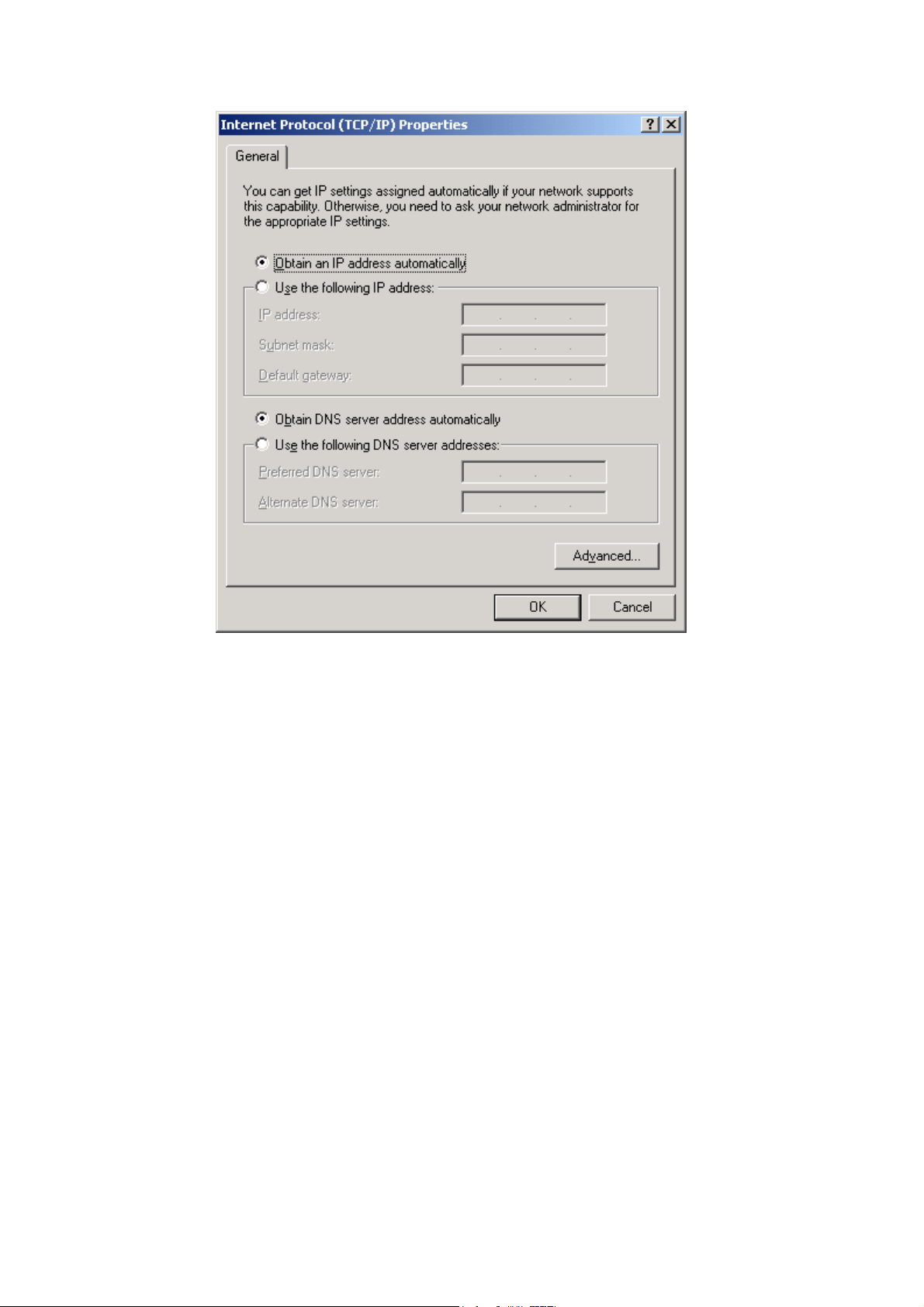
STEP 4: Click OK to submit these settings.
If you experience difficulty with DHCP mode, you can try static IP mode instead.
12
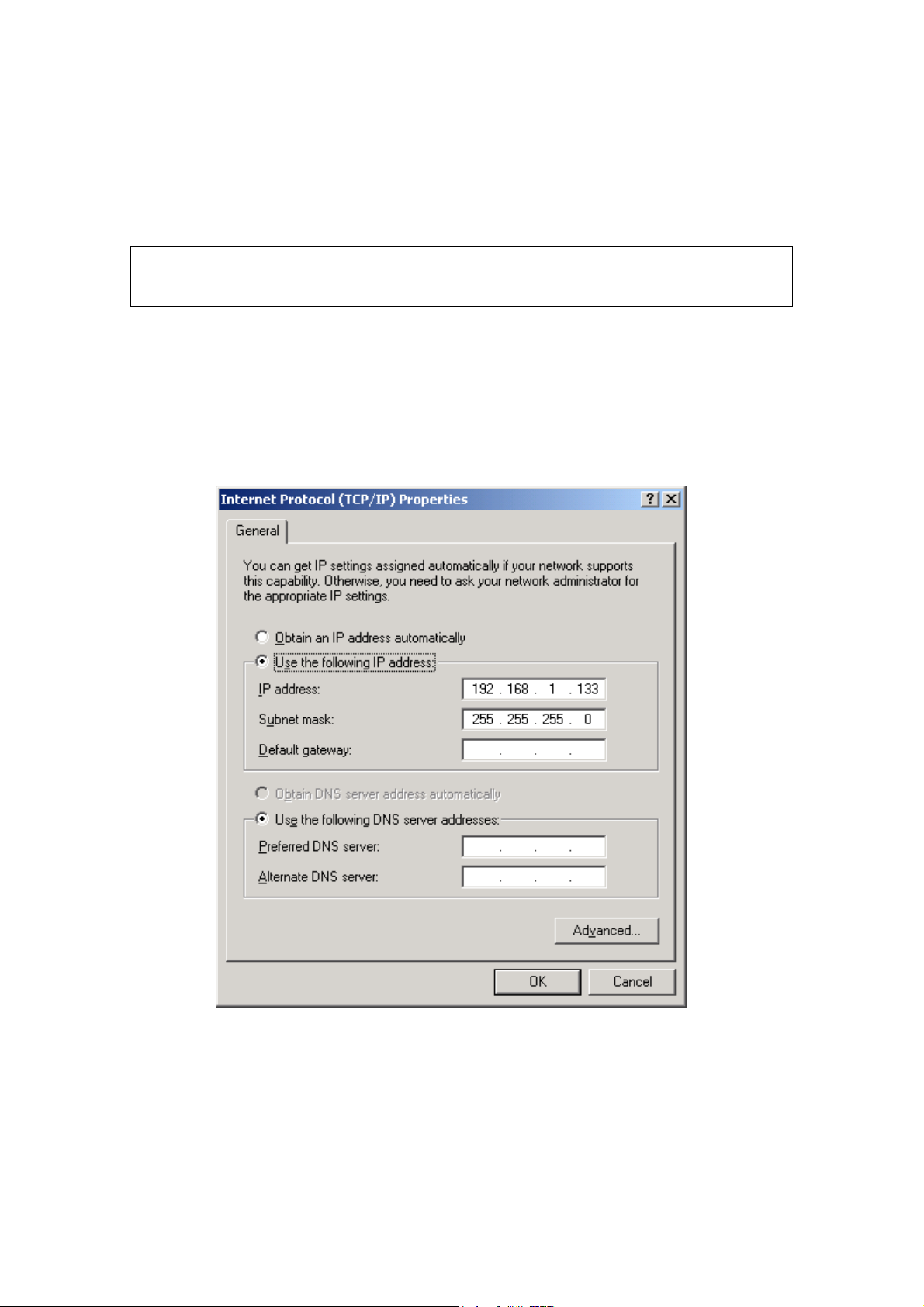
STATIC IP MODE
In static IP mode, you assign IP settings to your PC manually.
Follow these steps to configure your PC IP address to use subnet 192.168.1.x.
NOTE: The following procedure assumes you are running Windows XP.
However, the general steps involved are similar for most operating
systems (OS). Check your OS support documentation for further details.
STEP 1: From the Network Connections window, open Local Area Connection (You
may also access this screen by double-clicking the Local Area Connection
icon on your taskbar). Click the Properties button.
STEP 2: Select Internet Protocol (TCP/IP) and click the Properties button.
STEP 3: Change the IP address to the 192.168.1.x (1<x<255) subnet with subnet
mask of 255.255.255.0. The screen should now display as shown below.
STEP 4: Click OK to submit these settings.
13
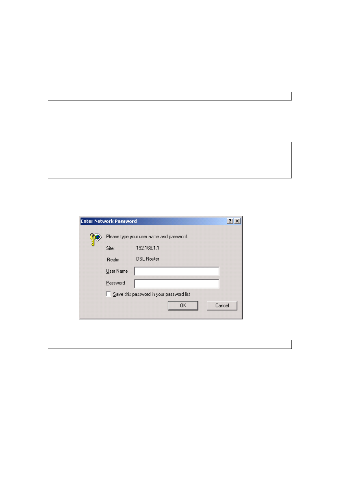
3.3 Login Procedure
Perform the following steps to login to the web user interface.
NOTE: The default settings can be found in 3.1 Default Settings.
STEP 1: Start the Internet browser and enter the default IP address for the device
in the Web address field. For example, if the default IP address is
192.168.1.1, type
NOTE: For local administration (i.e. LAN access), the PC running the browser
must be attached to the Ethernet, and not necessarily to the device.
For remote access (i.e. WAN), use the IP address shown on the Chapter 4
Device Information screen and login with remote username and
password.
STEP 2: A dialog box will appear, such as the one below. Enter the default
username and password, as defined in section
http://192.168.1.1.
3.1 Default Settings.
Click OK to continue.
NOTE: The login password can be changed later (see
14
8.6.1 Passwords).
 Loading...