

Comtrend 5374 User Manual

Step 3: On the Wireless Security screen, enable WSC by selecting Enabled
from the drop down list box and set the WSC AP Mode to Unconfigured.
100
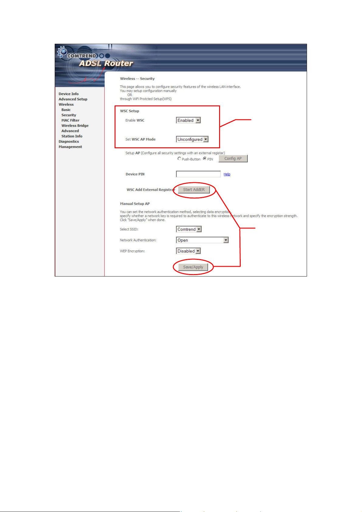
Step 3
Step 4
Step 4: Click the Save/Apply button at the bottom of the screen. The screen
will go blank while the router applies the new Wireless settings. When
the screen returns, press the Start AddER button, as shown above.
101
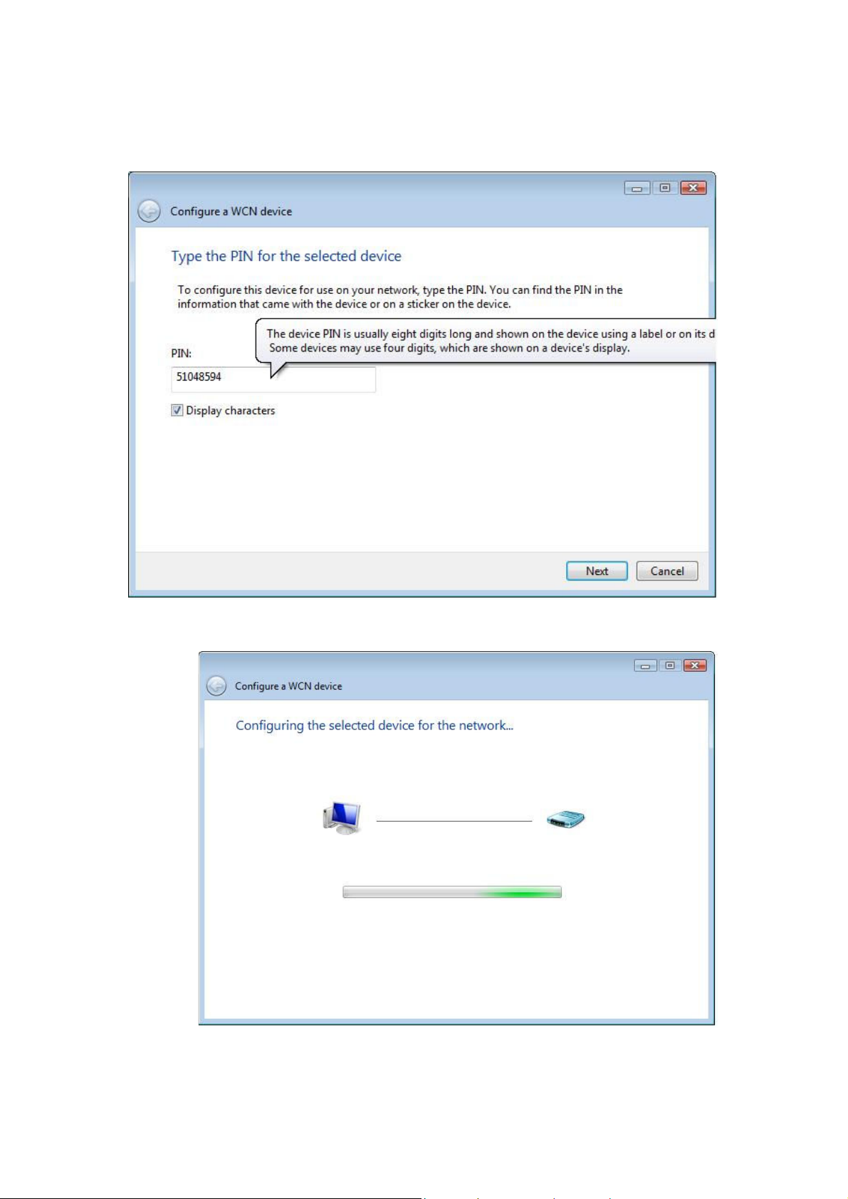
Step 5: Now return to the Network folder and click the BroadcomAP icon. A
dialog box will appear asking for the Device PIN number. Enter the
Device PIN as shown on the Wireless Security screen. Click Next.
Step 6: Windows Vista will attempt to configure the wireless security settings.
Step 7: If successful, the security settings will match those in Windows Vista.
102
Appendix F - Printer Server
These steps explain the procedure for enabling the Printer Server.
NOTE: This function only applies to models with an USB host port.
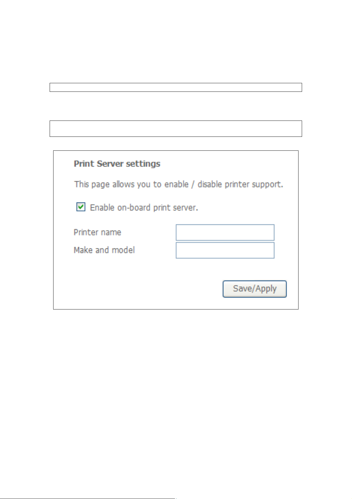
STEP 1: Enable Print Server from Web User Interface. Select Enable on-board
print server checkbox and enter Printer name and Make and model
NOTE: The Printer name can be any text string up to 40 characters.
The Make and model can be any text string up to 128 characters.
103
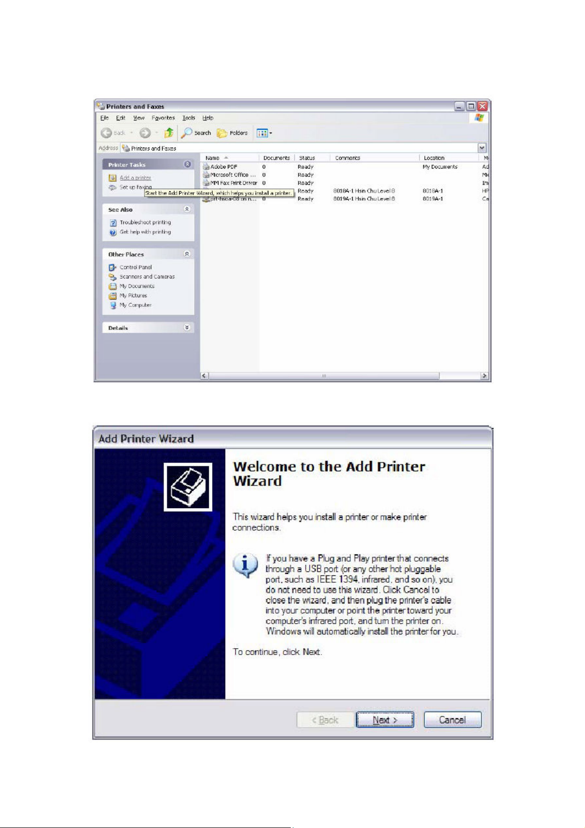
STEP 2: Go to the Printers and Faxes application in the Control Panel and
select the Add a printer function (as located on the side menu below).
STEP 3: Click Next to continue when you see the dialog box below.
104
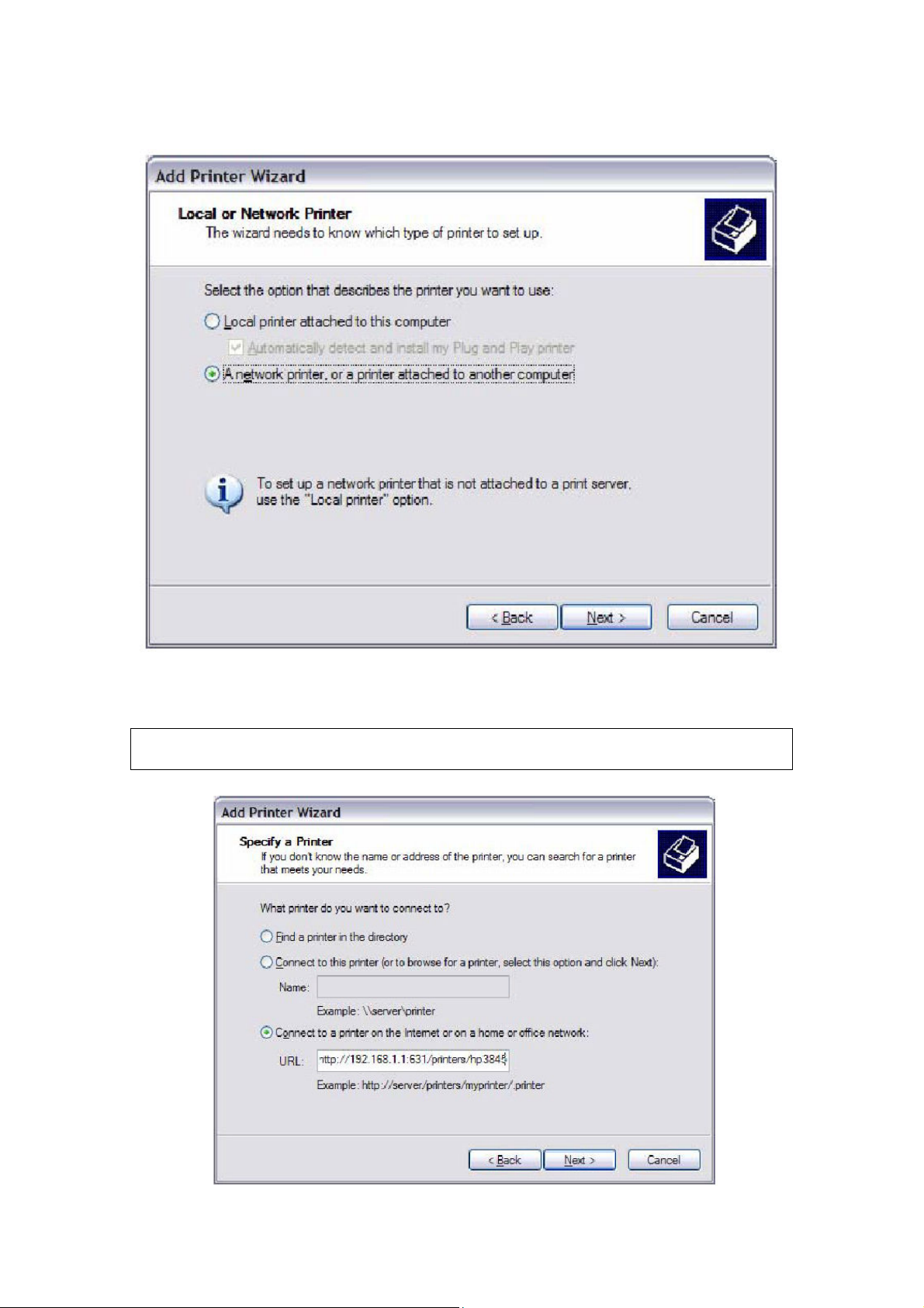
STEP 4: Select Network Printer and click Next.
STEP 5: Select Connect to a printer on the Internet and enter your printer link.
(e.g. http://192.168.1.1:631/printers/hp3845) and click Next.
NOTE: The printer name must be the same name entered in the ADSL modem
WEB UI “printer server setting” as in step 1.
105
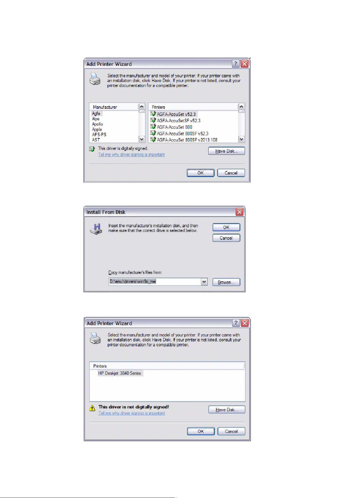
STEP 6: Click Have Disk and insert the printer driver CD.
STEP 7: Select driver file directory on CD-ROM and click OK.
STEP 8: Once the printer name appears, click OK.
106
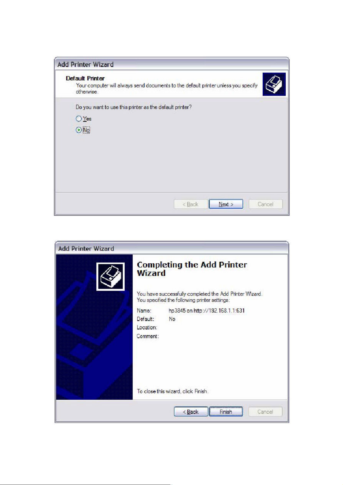
STEP 9: Choose Yes or No for default printer setting and click Next.
STEP 10: Click Finish.
107
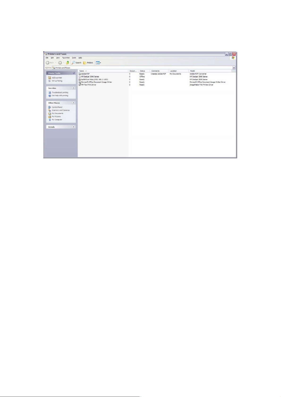
STEP 11: Check the status of printer from Windows Control Panel, printer window.
Status should show as Ready.
108
Appendix G - Connection Setup
Creating a WAN connection is a two-stage process.
1 - Setup a Layer 2 Interface (ATM, PTM or Ethernet).
2 - Add a WAN connection to the Layer 2 Interface.
The following sections describe each stage in turn.
G1 ~ Layer 2 Interfaces
Every layer2 interface operates in one of three modes: Default, VLAN Mux or MSC.
A short introduction to each of these three modes is included below for reference.
It is important to understand the differences between these connection modes, as
they determine the number and types of connections that may be configured.
DEFAULT MODE
In this mode there is a 1:1 relationship between interfaces and WAN connections, in
that an interface in default mode supports just one connection. However, unlike the
multiple connection modes described below, it supports all five connection types.
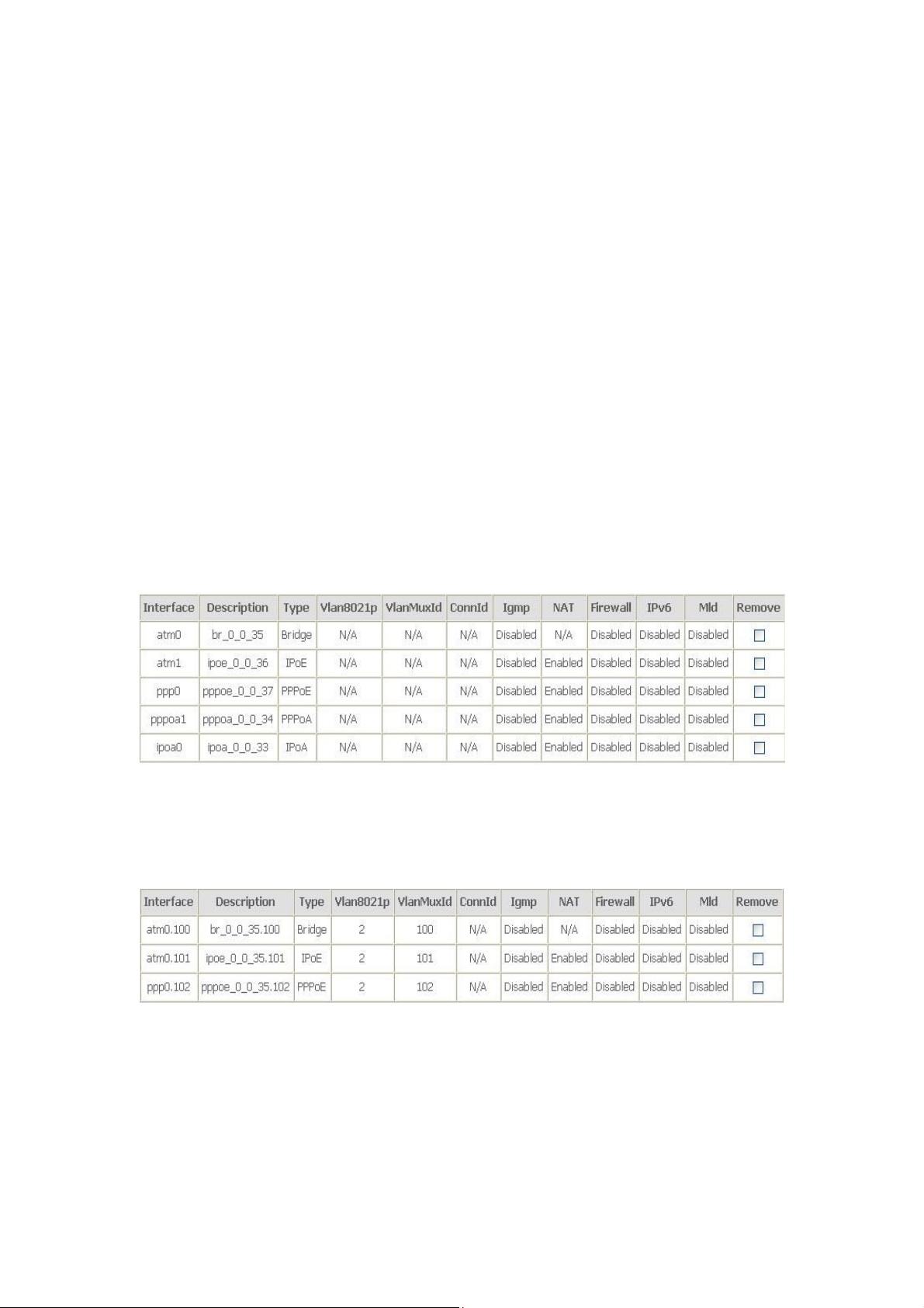
The figure below shows the five connection types available in ATM default mode.
VLAN MUX MODE
This mode uses VLAN tags to allow for multiple connections over a single interface.
PPPoE, IPoE, and Bridge are supported while PPPoA and IPoA connections are not.
The figure below shows multiple connections over a single VLAN Mux interface.
MSC MODE
Multi-Service Connection (MSC) mode supports multiple connections over a single
interface. As with VLAN Mux mode, PPPoA and IPoA connection types are not
supported, while Bridging is unavailable for Ethernet WAN interfaces. After adding
WAN connections to an interface, you must also create an Interface Group to
connect LAN/WAN interfaces (see
section G3 ~ More About MSC Mode).
109
G1.1 ATM Interfaces
Follow these procedures to configure an ATM interface.
NOTE: The CT-5374 supports up to 16 ATM interfaces.
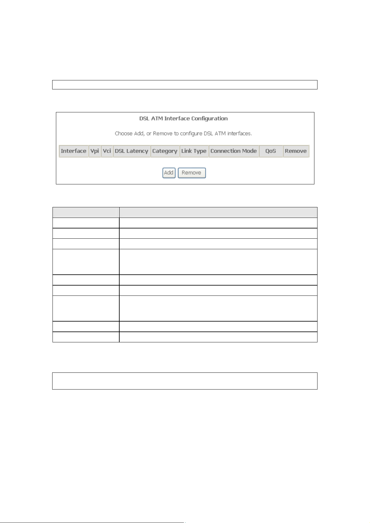
STEP 1: Go to Advanced Setup Layer2 Interface ATM Interface.
This table is provided here for ease of reference.
Heading Description
Interface WAN interface name.
VPI ATM VPI (0-255)
VCI ATM VCI (32-65535)
DSL Latency
{Path0} portID = 0
{Path1} port ID = 1
{Path0&1} port ID = 4
Category ATM service category
Link Type Choose EoA (for PPPoE, IPoE, and Bridge), PPPoA, or IPoA.
Connection Mode Default Mode – Single service over one connection
Vlan Mux Mode – Multiple Vlan service over one connection
MSC Mode – Multiple Service over one Connection
QoS Quality of Service (QoS) status
Remove Select items for removal
STEP 2: Click Add to proceed to the next screen.
NOTE: To add WAN connections to one interface type, you must delete existing
connections from the other interface type using the remove button.
110
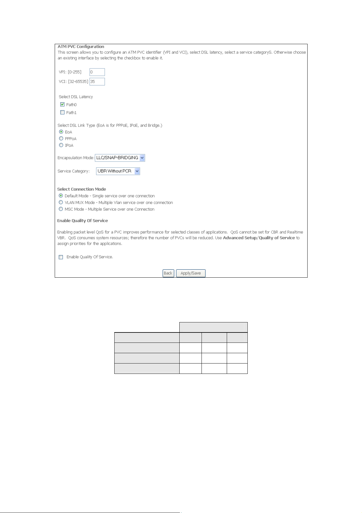
There are many settings here including: VPI/VCI, DSL Latency, DSL Link Type,
Encapsulation Mode, Service Category, Connection Mode and Quality of Service.
The table below shows xDSL Link Type availability with each Connection Mode.
xDSL Link Type
Connection Mode EoA* PPPoA IPoA
Default Mode OK OK OK
VLAN Mux Mode OK X X
MSC Mode OK X X
* EoA includes PPPoE, IPoE, and Bridge link types.
Here are the available encapsulations for each xDSL Link Type:
EoA- LLC/SNAP-BRIDGING, VC/MUX
PPPoA- VC/MUX, LLC/ENCAPSULATION
IPoA- LLC/SNAP-ROUTING, VC MUX
STEP 3: Click Apply/Save to confirm your choices.
111
 Loading...