

Page 1

Comtech EF Data is an
AS9100 Rev B / ISO9001:2000 Registered Company
RCS20
M:N Redundancy Switch
Installation and Operation Manual
IMPORTANT NOTE: The information contained in this document supersedes all previously published information
regarding this product. Product specifications are subject to change without prior notice.
MN-RCS20 Revision 14
Page 2

Page 3

Comtech EF Data is an
AS9100 Rev B / ISO9001:2000 Registered Company
RCS20
M:N Redundancy Switch
Installation and Operation Manual
Part Number MN-RCS20
Revision 14
Comtech EF Data, 2114 West 7th Street, Tempe, Arizona 85281 USA, 480.333.2200, FAX: 480.333.2161
Copyright © Comtech EF Data, 2012. All rights reserved. Printed in the USA.
Page 4

RCS20 M:N Redundancy Switch Rev. 14
Table of Contents MN-RCS20
This page is intentionally blank.
ii
Page 5

Table of Contents
TABLEOFCONTENTS.........................................................................................................................III
PREFACE..................................................................................................................................................XI
AboutthisManual.............................................................................................................................................xi
ReportingCommentsorSuggestionsConcerningthisManual................................................................................xi
Copyright............................................................................................................................... ............................ xi
PatentsandTrademarks....................................................................................................................................xi
ConventionsandReferences.............................................................................................................................xii
RelatedDocuments.................................................................................................................................................xii
MetricConversion...................................................................................................................................................xii
Warnings,Cautions,andNotes...............................................................................................................................xii
RecommendedStandardDesignations...................................................................................................................xii
SafetyandCompliance.....................................................................................................................................xiii
ElectricalSafetyandCompliance...........................................................................................................................xiii
ElectricalInstallation..............................................................................................................................................xiii
Battery....................................................................................................................................................................xiii
Grounding..............................................................................................................................................................xiii
Fuses.......................................................................................................................................................................xiv
OperatingEnvironment..........................................................................................................................................xiv
EuropeanUnionRadioEquipmentandTelecommunicationsTerminalEquipment(R&TTE)Directive(1999/5/EC)
andEN301489‐1....................................................................................................................................................xv
EuropeanUnionElectromagneticCompatibility(EMC)Directive(2004/108/EC)..............................................xv
EuropeanUnionLowVoltageDirective(LVD)(2006/95/EC)..............................................................................xv
EuropeanUnionRoHSDirective(2002/95/EC)..................................................................................................xvi
EuropeanUnionTelecommunicationsTerminalEquipmentDirective(91/263/EEC).......................................xvi
CEMark..............................................................................................................................................................xvi
WarrantyPolicy..............................................................................................................................................xvii
LimitationsofWarranty........................................................................................................................................xvii
ExclusiveRemedies..............................................................................................................................................xviii
GettingHelp....................................................................................................................................................xix
ContactingComtechEFData..................................................................................................................................xix
ReturningaProductforUpgradeorRepair............................................................................................................xx
CHAPTER1. INTRODUCTION......................................................................................................1–1
1.1 Overview............................................................................................................................................1–1
1.2 Features.............................................................................................................................................1–1
1.3 RCS20SwitchingSystemComponents.................................................................................................1–2
1.3.1 RCU20RedundancyControlUnit.............................................................................................................1–2
1.3.2 DigitalDataSwitch(DDS20)Configurations.............................................................................................1–3
1.3.2.1 UniversalDDS20..............................................................................................................................1–4
iii
Page 6

RCS20 M:N Redundancy Switch Rev. 14
Table of Contents MN-RCS20
1.3.2.2 DDS20‐ASI‐MorDDS20‐G703‐M(Modulator‐only)........................................................................1–5
1.3.2.3 DDS20‐ASIorDDS20‐G.703‐D(Demodulator‐only)........................................................................1–6
1.3.2.4 DDS20‐GigE(10/100/1000GigabitEthernet)BackupSwitch..........................................................1–7
1.3.3 IntermediateFrequencySwitch(IFS20)Configurations...........................................................................1–8
1.3.3.1 70/140IFS20....................................................................................................................................1–8
1.3.3.2 L‐BandIFS20(TransmitOnly)..........................................................................................................1–9
1.3.3.3 L‐BandIFS20(Transmit&Receive)................................................................................................1–10
CHAPTER2. INSTALLATION.......................................................................................................2–1
2.1 Overview............................................................................................................................................2–1
2.2 UnpackingtheUnit.............................................................................................................................2–2
2.2.1 TestDataSheet........................................................................................................................................2–2
2.3 RemovalandAssembly.......................................................................................................................2–3
2.4 MountingConsiderations....................................................................................................................2–3
2.5 Storage...............................................................................................................................................2–4
2.6 ConnectingtheRCS20.........................................................................................................................2–4
2.7 SystemCablingConfiguration.............................................................................................................2–4
2.8 ModemCheckoutandInitialPower‐Up...............................................................................................2–4
CHAPTER3. THEORYOFOPERATION.....................................................................................3–1
3.1 Overview............................................................................................................................................3–1
3.2 RCU20MajorAssemblies....................................................................................................................3–1
3.2.1 CentralProcessingUnit(CPU)Board.......................................................................................................3–1
3.2.2 FrontPanel...............................................................................................................................................3–2
3.2.3 ControllerInterfaceModule....................................................................................................................3–2
3.2.4 ClockDistributionModule(Optional)......................................................................................................3–2
3.2.5 RedundantPowerSupplies......................................................................................................................3–2
3.2.6 EthernetModule(Optional).....................................................................................................................3–2
3.2.7 BankControlModule...............................................................................................................................3–2
3.2.8 RCU20BackPanel....................................................................................................................................3–2
3.3 IFS20MajorAssemblies......................................................................................................................3–2
3.3.1 IFSwitchRelays............................................................................................................................... .........3–3
3.3.2 IFS20BackPanel/FrontPanel..................................................................................................................3–3
3.4 DDS20MajorAssemblies....................................................................................................................3–3
3.4.1 Motherboard............................................................................................................................................3–3
3.4.2 Slide‐InDataSwitchInterfaceModules...................................................................................................3–3
3.4.3 Housing....................................................................................................................................................3–3
3.4.4 DDS20BackPanel....................................................................................................................................3–4
3.5 RCS20ChannelDefinitions..................................................................................................................3–4
iv
Page 7

RCS20 M:N Redundancy Switch Rev. 14
Table of Contents MN-RCS20
CHAPTER4. USERINTERFACES.................................................................................................4–1
4.1 OperatingProcedures.........................................................................................................................4–1
4.2 FrontPanelInterface..........................................................................................................................4–2
4.2.1 ModemControlKeys................................................................................................................................4–3
4.2.1.1 MODEMMODCONFIG....................................................................................................................4–3
4.2.1.2 MODEMDEMODCONFIG................................................................................................................4–3
4.2.1.3 MODEMINTFCCONFIG...................................................................................................................4–3
4.2.1.4 MODEMMONITOR..........................................................................................................................4–3
4.2.1.5 MODEMTEST..................................................................................................................................4–3
4.2.1.6 MODEMALARMS............................................................................................................................4–3
4.2.2 LCDFrontPanelDisplay...........................................................................................................................4–3
4.2.3 ResetAlarmsKey......................................................................................................................................4–4
4.2.4 ModuleSelectKey............................................................................................................................... .....4–4
4.2.5 SwitchStatusLEDs...................................................................................................................................4–4
4.2.6 NumericKeypad............................................................................................................................... ........4–4
4.2.7 SoftKeys(S1‐S4).....................................................................................................................................4–5
4.2.8 SwitchControlKeys............................................................................................................................... ...4–5
4.2.8.1 SWITCHCONFIGSWITCH.................................................................................................................4–5
4.2.8.2 SWITCHCONFIGSYSTEM.................................................................................................................4–5
4.2.8.3 SWITCHMONITOR/ALARMS............................................................................................................4–5
4.2.8.4 SWITCHTEST...................................................................................................................................4–5
4.2.9 BasicFrontPanelControls.......................................................................................................................4–5
4.2.9.1 ChangingparametersfromtheFrontPanel....................................................................................4–5
4.2.9.2 MovingtotheNextScreeninaMenuTree....................................................................................4–6
4.2.9.3 MovingtothePreviousScreeninaMenuTree..............................................................................4–6
4.3 FrontPanelScreens............................................................................................................................4–7
4.3.1 CONFIGSWITCHMenuTree....................................................................................................................4–8
4.3.1.1 MODEMCHANNELCONNECTIONS..................................................................................................4–8
4.3.1.2 MODEMADDRESSES.......................................................................................................................4–9
4.3.1.3 MODEMCHANNELCONNECTIONTEST.........................................................................................4–10
4.3.1.4 MODEM9/BACKUP2CONFIGURATION......................................................................................4–11
4.3.1.4.1 MODEM9/BACKUP2MODE..................................................................................................4–12
4.3.1.5 BACKUPMODECONFIGURATION..................................................................................................4–13
4.3.1.5.1 BACKUPMODE1SELECT..........................................................................................................4–14
4.3.1.5.2 BACKUPMODE2SELECT..........................................................................................................4–15
4.3.1.6 MODEMSWITCHINGSTYLE...........................................................................................................4–16
4.3.1.7 AUTOMODEBACKUPASSIGNMENTSUMMARY...........................................................................4–17
4.3.1.7.1 AUTOMODEBACKUP1ASSIGNMENTPROGRAM...................................................................4–19
4.3.1.7.2 AUTOMODEBACKUP2ASSIGNMENTPROGRAM...................................................................4–20
4.3.1.7.3 BACKUPASSIGNMENTS,PRIORITIES........................................................................................4–21
4.3.1.8 IFS20LDEMODBKUPASSIGNMENTSUMMARY............................................................................4–22
4.3.1.9 LEARN/BACKUPTESTCONFIGURATION........................................................................................4–23
4.3.1.9.1 LEARNTESTCONFIGURATION..................................................................................................4–24
4.3.1.9.2 BACKUPTESTCONFIGURATION...............................................................................................4–25
4.3.1.9.3 COPYMODEMCONFIGURATION.............................................................................................4–26
4.3.1.9.4 MODFAULTDELAY...................................................................................................................4–27
4.3.1.9.5 DEMODFAULTDELAY..............................................................................................................4–28
4.3.1.9.6 DEMODAQUDELAY.................................................................................................................4–29
4.3.1.9.7 FORCEMANUALBACKUP.........................................................................................................4–30
4.3.1.9.7.1 FORCEMANUALBACKUP1...............................................................................................4–31
4.3.1.9.7.2 FORCEMANUALBACKUP2...............................................................................................4–32
v
Page 8

RCS20 M:N Redundancy Switch Rev. 14
Table of Contents MN-RCS20
4.3.2 CONFIGSYSTEMMenuTree...................................................................................................................4–33
4.3.2.1 CONTROLMODECONFIGURATION...............................................................................................4–33
4.3.2.2 TERMINALPORTCONFIGURATION...............................................................................................4–34
4.3.2.2.1 TERMINALPORTBAUDRATE...................................................................................................4–35
4.3.2.2.2 TERMINALPORTEMULATION..................................................................................................4–36
4.3.2.3 REMOTEPORTCONFIGURATION..................................................................................................4–37
4.3.2.3.1 REMOTEPORTBAUDRATECONFIGURATION..........................................................................4–38
4.3.2.3.2 REMOTEPORTADDRESS..........................................................................................................4–39
4.3.2.3.3 REMOTEPORTPROTOCOLCONFIGURATION..........................................................................4–40
4.3.2.4 MODEMPORTCONFIGURATION...................................................................................................4–41
4.3.2.4.1 MODEMPORTBAUDRATECONFIGURATION..........................................................................4–42
4.3.2.5 KEYCLICKCONFIGURATION..........................................................................................................4–43
4.3.2.6 TIME/DATECONFIGURATION......................................................................................................4–44
4.3.2.6.1 SETDATE..................................................................................................................................4–45
4.3.2.6.2 SETTIME...................................................................................................................................4–46
4.3.2.7 LCDCONTRASTADJUSTMENT.......................................................................................................4–47
4.3.2.8 LCDBACKLIGHTTIMEOUT.............................................................................................................4–48
4.3.2.9 BANKCONTROLCONFIGURATION................................................................................................4–49
4.3.2.9.1 IFSBANKCONTROLLER............................................................................................................4–50
4.3.2.9.2 DDSBANKCONTROLLER..........................................................................................................4–51
4.3.2.9.3 COMBINEIFL(IFSL‐BandDemodulatorOnly)..........................................................................4–52
4.3.2.9.4 CARRIER‐IN‐CARRIERMODEMS...............................................................................................4–53
4.3.2.9.5 CnCSWITCHING.......................................................................................................................4–54
4.3.2.9.6 SOFTWARE/FIRMWAREVERSIONS..........................................................................................4–55
4.3.2.9.7 REFERENCEDISTRIBUTIONCONFIGURATION..........................................................................4–56
4.3.2.9.8 RDMFALLBACKCONFIGURATION............................................................................................4–57
4.3.2.9.9 RDMFALLBACKCONFIGURATION............................................................................................4–58
4.3.2.9.10 MODEMSERVICEMODE........................................................................................................4–59
4.3.2.9.11 MODEMSERVICEMODESELECTION......................................................................................4–60
4.3.2.9.12 IFS20‐LDEMODBKUPAssignmentSummary........................................................................4–61
4.3.3 MONITOR/ALARMSMenuTree.............................................................................................................4–62
4.3.3.1 EXPANSIONSLOTMONITOR..........................................................................................................4–62
4.3.3.2 MOD/DEMODFAULTMONITOR..................................................................................................4–63
4.3.3.3 EVENTS..........................................................................................................................................4–64
4.3.3.4 NEXTEVENTSSCREEN...................................................................................................................4–64
4.3.3.5 SWITCHMAJORALARMS1............................................................................................................4–65
4.3.3.6 SWITCHMAJORALARMS2............................................................................................................4–66
4.3.3.7 SWITCHMINORALARMS1............................................................................................................4–67
4.3.3.8 SWITCHMINORALARMS2............................................................................................................4–68
4.3.4 TESTMenuTree.....................................................................................................................................4–69
4.3.4.1 SWITCHSYSTEMTESTS..................................................................................................................4–69
4.3.4.1.1 MODEMCHANNELCONNECTIONTEST....................................................................................4–70
4.3.4.1.2 MODEMPARAMETERCOMPATIBILITYTEST............................................................................4–71
4.3.4.1.3 LAMPTEST...............................................................................................................................4–72
4.3.4.2 SWITCHSYSTEMTESTSScreen2...................................................................................................4–73
4.3.4.2.1 REMOTEPORTTEST.................................................................................................................4–74
4.4 RemoteInterface..............................................................................................................................4–75
4.4.1 HostComputerRemoteCommunications.............................................................................................4–75
4.5 TerminalPortControl.......................................................................................................................4–76
4.5.1 TerminalInterface..................................................................................................................................4–76
vi
Page 9

RCS20 M:N Redundancy Switch Rev. 14
Table of Contents MN-RCS20
CHAPTER5. ELECTRICALINTERFACES...................................................................................5–1
5.1 Overview............................................................................................................................................5–1
5.2 RCU20BackPanelConnectors.............................................................................................................5–2
5.2.1 Slide‐OutRedundantPowerSupply/SwitchModules..............................................................................5–2
5.2.2 ChassisGround.........................................................................................................................................5–2
5.2.3 ExpansionSlots.........................................................................................................................................5–3
5.2.3.1 ReferenceDistributionModule.......................................................................................................5–3
5.2.3.1.1 J1|EXTAIN(ExternalInputA)..................................................................................................5–4
5.2.3.1.2 J2|EXTBIN(ExternalInputB)..................................................................................................5–5
5.2.3.1.3 InternalReference(Option1)....................................................................................................5–5
5.2.3.1.4 InternalReference(Option2)....................................................................................................5–5
5.2.3.1.5 ReferenceOutputs(J3|OUT1,J4|OUT2,J5|OUT3,J6|OUT4)........................................5–5
5.2.3.1.6 MicroprocessorInterface...........................................................................................................5–5
5.2.3.1.7 BoardOutline.............................................................................................................................5–6
5.2.3.2 CPUTerrestrialI/OCard..................................................................................................................5–6
5.2.3.2.1 J1|ALARMS...............................................................................................................................5–6
5.2.3.2.2 J2|TERMINAL............................................................................................................................5–7
5.2.3.2.3 J3|REMOTE...............................................................................................................................5–7
5.2.3.3 BankControlI/OCard.....................................................................................................................5–8
5.2.3.3.1 J1|MODEMREMOTE................................................................................................................5–8
5.2.3.3.2 J2|IFS20....................................................................................................................................5–9
5.2.3.3.3 J3|DDS20................................................................................................................................5–10
5.3 DDS20UniversalModemDataSwitch...............................................................................................5–11
5.3.1 DDS20–UniversalSwitchFrontPanelInterface....................................................................................5–11
5.3.1.1 DDS20DataSwitchModule...........................................................................................................5–11
5.3.1.1.1 ConfiguringDataSwitchModuleDIPSwitches........................................................................5–12
5.3.1.1.2 DDS20DataSwitchModuleConnectors..................................................................................5–14
5.3.1.1.2.1 J1|SD(SendData)...........................................................................................................5–14
5.3.1.1.2.2 J2|DDO(DropDataOut).................................................................................................5–14
5.3.1.1.2.3 J3|IDI(InsertDataIn)......................................................................................................5–15
5.3.1.1.2.4 J4|RD(ReceiveData)......................................................................................................5–15
5.3.1.1.2.5 J5|ESCVSC(EscapeAudio).............................................................................................5–15
5.3.1.1.2.6 J9|ES/ES(EarthStation‐to‐EarthStation).......................................................................5–16
5.3.1.1.2.7 J7|ESCALM(EngineeringServiceCircuitsAlarmInterface)...........................................5–17
5.3.1.1.2.8 J8|8KDATA(ESC8KDataInterface)...............................................................................5–18
5.3.1.1.2.9 J9|G.703(G.703Balanced).............................................................................................5–19
5.3.1.1.2.10 J10|SYNCDATA(SynchronousData)............................................................................5–20
5.3.2 DDS20–UniversalSwitchBackPanelConnectors.................................................................................5–22
5.3.2.1 J1|MODEM1throughJ8|MODEM868‐PinHighDensityMinDSUBConnectors....................5–22
5.3.2.2 J9|MODEM9|BACKUP268‐PinHighDensityMinDSUBConnector.......................................5–25
5.3.2.3 J10|BACKUP168‐PinHighDensityMinDSUBConnector..........................................................5–25
5.3.2.4 J31|RCU‐2015‐pinHigh‐DensityDSUBConnector.....................................................................5–25
5.4 DDS‐20GigE(10/100/1000Ethernet)BackupSwitch.........................................................................5–26
5.4.1 DDS‐20–GigESwitchFrontPanelConnectors......................................................................................5–26
5.4.1.1 J1|CH1DATAINthroughJ9|CH9DATAIN...............................................................................5–26
5.4.2 DDS‐20–GigESwitchBackPanelConnectors.......................................................................................5–26
5.4.2.1 J10|CH9DATAOUTthroughJ18|CH1DATAOUT....................................................................5–26
5.4.2.2 J19|BUDATAOUT.......................................................................................................................5–26
5.4.2.3 J20|MODEMFAULTMONITOR....................................................................................................5–27
5.4.2.4 J21|RCU20...................................................................................................................................5–28
vii
Page 10

RCS20 M:N Redundancy Switch Rev. 14
Table of Contents MN-RCS20
5.5 IFS20IntermediateFrequencySwitchUnits.......................................................................................5–29
5.5.1 IFS2070/140MHzUnit..........................................................................................................................5–29
5.5.1.1 IFS2070/140MHzUnitConnectors–FrontPanel........................................................................5–29
5.5.1.1.1 J1|UPAUX..............................................................................................................................5–29
5.5.1.1.2 J2|UP1....................................................................................................................................5–29
5.5.1.1.3 J3|UP2....................................................................................................................................5–29
5.5.1.1.4 J4|UP3....................................................................................................................................5–29
5.5.1.1.5 J5|UP4....................................................................................................................................5–30
5.5.1.1.6 J6|UP5....................................................................................................................................5–30
5.5.1.1.7 J7|UP6....................................................................................................................................5–30
5.5.1.1.8 J8|UP7....................................................................................................................................5–30
5.5.1.1.9 J9|UP8....................................................................................................................................5–30
5.5.1.1.10 J10|MODTEST2...................................................................................................................5–30
5.5.1.1.11 J12|MODTEST1...................................................................................................................5–30
5.5.1.1.12 J24|DNAUX2.......................................................................................................................5–30
5.5.1.1.13 J25|DNAUX1.......................................................................................................................5–30
5.5.1.1.14 J26|DN1...............................................................................................................................5–30
5.5.1.1.15 J27|DN2...............................................................................................................................5–31
5.5.1.1.16 J28|DN3...............................................................................................................................5–31
5.5.1.1.17 J29|DN4...............................................................................................................................5–31
5.5.1.1.18 J30|DN5...............................................................................................................................5–31
5.5.1.1.19 J31|DN6...............................................................................................................................5–31
5.5.1.1.20 J32|DN7...............................................................................................................................5–31
5.5.1.1.21 J33|DN8...............................................................................................................................5–31
5.5.1.2 IFS2070/140MHzUnitConnectors–BackPanel.........................................................................5–32
5.5.1.2.1 J11|MODBU2........................................................................................................................5–32
5.5.1.2.2 J13|MODBU1........................................................................................................................5–32
5.5.1.2.3 J14|MOD1.............................................................................................................................5–32
5.5.1.2.4 J15|MOD2.............................................................................................................................5–32
5.5.1.2.5 J16|MOD3.............................................................................................................................5–32
5.5.1.2.6 J17|MOD4.............................................................................................................................5–32
5.5.1.2.7 J18|MOD5.............................................................................................................................5–32
5.5.1.2.8 J19|MOD6.............................................................................................................................5–32
5.5.1.2.9 J20|MOD7.............................................................................................................................5–33
5.5.1.2.10 J21|MOD8...........................................................................................................................5–33
5.5.1.2.11 J22|DMDBU2...................................................................................................................... 5–33
5.5.1.2.12 J23|DMDBU1.......................................................................................................................5–33
5.5.1.2.13 J34|DMD1............................................................................................................................5–33
5.5.1.2.14 J35|DMD2............................................................................................................................5–33
5.5.1.2.15 J36|DMD3............................................................................................................................5–33
5.5.1.2.16 J37|DMD4............................................................................................................................5–33
5.5.1.2.17 J38|DMD5............................................................................................................................5–33
5.5.1.2.18 J39|DMD6............................................................................................................................5–33
5.5.1.2.19 J40|DMD7............................................................................................................................5–33
5.5.1.2.20 J41|DMD8............................................................................................................................5–34
5.5.1.2.21 J42|MCU‐20.........................................................................................................................5–34
5.5.2 IFS20LL‐BandUnit.................................................................................................................................5–35
5.5.2.1 IFS20LL‐BandUnitConnectors–FrontPanel...............................................................................5–35
5.5.2.1.1 J13|MODEM1........................................................................................................................5–35
5.5.2.1.2 J14|MODEM2........................................................................................................................5–35
5.5.2.1.3 J15|MODEM3........................................................................................................................5–35
5.5.2.1.4 J16|MODEM4........................................................................................................................5–35
5.5.2.1.5 J17|BUMODEM2|MODEM9..............................................................................................5–35
5.5.2.1.6 J18|MODEM5........................................................................................................................5–35
viii
Page 11

RCS20 M:N Redundancy Switch Rev. 14
Table of Contents MN-RCS20
5.5.2.1.7 J19|MODEM6........................................................................................................................5–36
5.5.2.1.8 J20|MODEM7........................................................................................................................5–36
5.5.2.1.9 J21|MODEM8........................................................................................................................5–36
5.5.2.1.10 J22|BUMODEM1................................................................................................................5–36
5.5.2.1.11 J23|DOWNCONVERTERPORTB..........................................................................................5–36
5.5.2.1.12 J24|DOWNCONVERTERPORTD..........................................................................................5–36
5.5.2.1.13 J25|DOWNCONVERTERPORTG..........................................................................................5–36
5.5.2.1.14 J26|DOWNCONVERTERPORTF..........................................................................................5–36
5.5.2.1.15 J27|DOWNCONVERTERPORTA..........................................................................................5–36
5.5.2.1.16 J28|DOWNCONVERTERPORTC..........................................................................................5–36
5.5.2.1.17 J29|DOWNCONVERTERPORTH..........................................................................................5–37
5.5.2.1.18 J30|DOWNCONVERTERPORTE..........................................................................................5–37
5.5.2.2 IFS20LL‐BandUnitConnectors–BackPanel................................................................................5–37
5.5.2.2.1 J1|UPCONV8.........................................................................................................................5–37
5.5.2.2.2 J2|UPCONV7.........................................................................................................................5–37
5.5.2.2.3 J3|UPCONV6.........................................................................................................................5–37
5.5.2.2.4 J4|UPCONV5.........................................................................................................................5–37
5.5.2.2.5 J5|UPCONV9.........................................................................................................................5–37
5.5.2.2.6 J6|UPCONV4..........................................................................................................................5–38
5.5.2.2.7 J7|UPCONV3..........................................................................................................................5–38
5.5.2.2.8 J8|UPCONV2..........................................................................................................................5–38
5.5.2.2.9 J9|UPCONV1..........................................................................................................................5–38
5.5.2.2.10 J10|DEMODBU2..................................................................................................................5–38
5.5.2.2.11 J11|DEMODBU1..................................................................................................................5–38
5.5.2.2.12 J12|POWER..........................................................................................................................5–38
CHAPTER6. MAINTENANCEANDTROUBLESHOOTING....................................................6–1
6.1 PeriodicMaintenance.........................................................................................................................6–1
6.2 AlarmMasks.......................................................................................................................................6–1
6.3 ActiveMajorAlarms...........................................................................................................................6–2
6.4 ActiveMinorAlarms...........................................................................................................................6–3
CHAPTER7. TECHNICALSPECIFICATIONS............................................................................7–1
7.1 GeneralSpecifications........................................................................................................................7–1
7.2 IFS20(70/140MHz)............................................................................................................................7–1
7.3 IFS20(L‐Band).....................................................................................................................................7–1
7.4 TerrestrialInterfaces...........................................................................................................................7–2
7.5 Options..............................................................................................................................................7–2
7.6 PowerandEnvironmental...................................................................................................................7–2
7.7 PhysicalCharacteristics.......................................................................................................................7–3
7.8 ComplementaryProducts...................................................................................................................7–3
ix
Page 12

RCS20 M:N Redundancy Switch Rev. 14
Table of Contents MN-RCS20
APPENDIXA. REMOTEOPERATIONS.....................................................................................A–1
A.1 HostComputerRemoteCommunications...........................................................................................A–1
A.1.1 ProtocolStructure...................................................................................................................................A–1
A.1.2 ProtocolWrapper....................................................................................................................................A–2
A.1.3 FrameDescriptionandBusHandshaking................................................................................................A–3
A.1.4 GlobalResponseOperationalCodes.......................................................................................................A–4
A.1.5 CollisionAvoidance.................................................................................................................................A–6
A.1.6 SoftwareCompatibility...........................................................................................................................A–7
A.1.7 FlowControlandTaskProcessing...........................................................................................................A–8
A.1.8 RLLPSummary.........................................................................................................................................A–9
A.2 RemotePortPacketStructure:.........................................................................................................A–10
A.2.1 RCS20SwitchCommandSet.................................................................................................................A–11
A.2.2 RCS20OpcodeCommandSet...............................................................................................................A–12
A.3 DETAILEDOPCODEDESCRIPTIONS....................................................................................................A–13
APPENDIXB. SYSTEMCABLINGCONFIGURATION.............................................................B–1
B.1 Overview............................................................................................................................................B–1
B.2 RCS20Interconnects...........................................................................................................................B–2
APPENDIXC. LBANDDEMODSWITCHSETUPANDCONFIGURATION........................C–1
x
Page 13

PREFACE
About this Manual
This manual describes the installation and operation for the Radyne RCS20 M:N Redundancy
Control, Switch. This is a document intended for the persons responsible for the operation and
maintenance of the RCS20.
Reporting Comments or Suggestions Concerning this Manual
Comments and suggestions regarding the content and design of this manual are appreciated. To
submit comments, please contact the Comtech EF Data Technical Publications Department:
TechnicalPublications@comtechefdata.com
Copyright
©2011, Comtech EF Data This manual is proprietary to Comtech EF Data and is intended for the
exclusive use of Comtech EF Data’s customers. No part of this document may in whole or in part,
be copied, reproduced, distributed, translated or reduced to any electronic or magnetic storage
medium without the express written consent of a duly authorized officer of Comtech EF Data.
Patents and Trademarks
See all of Comtech EF Data's Patents and Patents Pending at http://patents.comtechefdata.com.
Comtech EF Data acknowledges that all trademarks are the property of the trademark owners.
• DoubleTalk
• DoubleTalk
• Carrier-in-Carrier
®
is licensed from “Raytheon Applied Signal Technology”.
®
is a registered trademark of “Raytheon Applied Signal Technology”.
®
is a registered trademark of Comtech EF Data.
xi
Page 14
RCS20 M:N Redundancy Switch Rev. 14
Preface MN-RCS20
Conventions and References
Related Documents
The following documents are referenced in this manual:
• EN300-421 and EN301-210 ETSI
• ETSI EN302-307
• INTELSAT Earth Station Standards IESS-308, -309, -310, and -315
• EUTELSAT SMS
Metric Conversion
Metric conversion information is located on the inside back cover of this manual. This information
is provided to assist the operator in cross-referencing non-Metric to Metric conversions.
Warnings, Cautions, and Notes
A WARNING gives information about a possible hazard that MAY CAUSE
DEATH or SERIOUS INJURY.
A CAUTION gives information about a possible hazard that MAY CAUSE
INJURY or PROPERTY DAMAGE.
A NOTE gives important information about a task or the equipment.
Recommended Standard Designations
Recommended Standard (RS) Designations have been superseded by the new designation of the
Electronic Industries Association (EIA). References to the old designations are shown only when
depicting actual text displayed on the screen of the unit (RS-232, RS-485, etc.). All other references
in the manual will be shown with the EIA designations.
xii
Page 15
RCS20 M:N Redundancy Switch Rev. 14
Preface MN-RCS20
The user should carefully review the following information.
Safety and Compliance
Electrical Safety and Compliance
The RCS20 complies with the EN 60950 Safety of Information Technology Equipment
(Including Electrical Business Machines) safety standard.
IF THE UNIT IS OPERATED IN A VEHICLE OR MOVABLE INSTALLATION,
MAKE SURE THE UNIT IS STABLE. OTHERWISE, EN 60950 SAFETY IS NOT
GUARANTEED.
Electrical Installation
The RCS20 is rated for a nominal operating range of 100-240 volts AC; for the appropriately
equipped DC option, nominal operating range is 48 ±5 volts DC. The unit has a maximum power
consumption of 250 watts.
The installation and connection to the line supply must be made in compliance to local or national
wiring codes and regulations.
The RCS20 is shipped with line inlet cables suitable for use in the country of operation. If it is
necessary to replace these cables, ensure the replacement has an equivalent specification.
Examples of acceptable ratings for the cables include HAR, BASEC and HOXXX-X.
Examples of acceptable connector ratings include VDE, NF-USE, UL, CSA, OVE, CEBEC,
NEMKO, DEMKO, BS1636A, BSI, SETI, IMQ, KEMA-KEUR and SEV.
Battery
The RCS20 contains a Lithium Battery. DANGER OF EXPLOSION EXISTS
battery is incorrectly replaced. Replace only with the same or equivalent type
recommended by the manufacturer. Dispose of used batteries in accordance with local
and national regulations.
if the
Grounding
PROPER GROUNDING PROTECTION IS REQUIRED: The installation
instructions require that the integrity of the protective earth must be ensured and
that the equipment shall be connected to the protective earth connection at all times.
It is therefore imperative
user to ensure that the unit has been properly grounded using the ground stud
during installation, configuration, and operation for the
xiii
Page 16

RCS20 M:N Redundancy Switch Rev. 14
Preface MN-RCS20
provided on the rear panel of the unit.
• In Finland: "Laite on liitettävä suojamaadoituskoskettimilla varustettuun
pistorasiaan."
• In Norway: “Apparatet må tilkoples jordet stikkontakt.”
• In Sweden: “Apparaten skall anslutas till jordat uttag.”
Fuses
FOR CONTINUED OPERATOR SAFETY, ALWAYS REPLACE THE FUSES WITH
THE CORRECT TYPE AND RATING.
Typical for either slide-in power module on the rear panel of the RCU (Redundancy
Control Unit):
• For AC operation, the RCS20 requires two common 3.15 Amp/250 volts 20mm
x 5mm Slow-blow fuses that are contained within a fuse holder that is press-fit
into the body of the IEC power inlet module.
• For DC operation, no fuses are required.
Operating Environment
DO NOT OPERATE THE UNIT IN ANY OF THESE EXTREME OPERATING
CONDITIONS:
• AMBIENT TEMPERATURES LESS THAN 0°C (32°F) OR MORE THAN
50°C (122°F). (MAXIMUM STORAGE TEMPERATURE ALLOWED IS 20°C (-4°F) TO 70°C (158°F)).
• PRECIPITATION, CONDENSATION, OR HUMID ATMOSPHERES OF
MORE THAN 95% RELATIVE HUMIDITY.
• UNPRESSURIZED ALTITUDES OF MORE THAN 2000 METRES (6561.7
FEET).
• EXCESSIVE DUST.
• FLAMMABLE GASES.
• CORROSIVE OR EXPLOSIVE ATM OSPHERES.
xiv
Page 17
RCS20 M:N Redundancy Switch Rev. 14
Preface MN-RCS20
European Union Radio Equipment and Telecommunications Terminal Equipment (R&TTE) Directive (1999/5/EC) and EN 301 489-1
Independent testing verifies that the unit complies with the European Union R&TTE Directive, its
reference to EN 301 489-1 (Electromagnetic compatibility and Radio spectrum Matters [ERM];
ElectroMagnetic Compatibility [EMC] standard for radio equipment and services, Part 1:
Common technical requirements), and the Declarations of Conformity for the applicable
directives, standards, and practices that follow:
European Union Electromagnetic Compatibility (EMC) Directive (2004/108/EC)
• Emissions: EN 55022 Class B – Limits and Methods of Measurement of Radio
Interference Characteristics of Information Technology Equipment.
• Immunity: EN 55024 – Information Technology Equipment: Immunity Characteristics,
Limits, and Methods of Measurement.
• EN 61000-3-2 – Harmonic Currents Emission
• EN 61000-3-3 – Voltage Fluctuations and Flicker.
• Federal Communications Commission Federal Code of Regulation FCC Part 15,
Subpart B.
TO ENSURE THAT THE UNIT COMPLIES WITH THESE STANDARDS,
OBEY THESE INSTRUCTIONS:
• Use coaxial cable that is of good quality (e.g., RG58/U (50Ω) or RG59/U (75Ω)) for
connections to the IF Tx and Rx (transmit and receive) BNC female connectors.
• Use Type 'D' connectors that have back-shells with continuous metallic shielding.
Type ‘D’ cabling must have a continuous outer shield (either foil or braid, or both). The
shield must be bonded to the back-shell.
• Operate the unit with its cover on at all times.
European Union Low Voltage Directive (LVD) (2006/95/EC)
Symbol Description
<HAR> Type of power cord required for use in the European Community.
!
CAUTION: Double-pole/Neutral Fusing
ACHTUNG: Zweipolige bzw. Neutralleiter-Sicherung
xv
Page 18

RCS20 M:N Redundancy Switch Rev. 14
Preface MN-RCS20
International Symbols
Symbol Definition Symbol Definition
Alternating Current
Fuse
Protective Earth
Chassis Ground
For additional symbols, refer to Warnings, Cautions and Notes listed earlier in this
Preface.
European Union RoHS Directive (2002/95/EC)
This unit satisfies (with exemptions) the requirements specified in the European Union Directive
on the Restriction of Hazardous Substances in Electrical and Electronic Equipment (EU RoHS,
Directive 2002/95/EC).
European Union Telecommunications Terminal Equipment Directive (91/263/EEC)
In accordance with the European Union Telecommunications Terminal Equipment Directive
91/263/EEC, the unit should not be directly connected to the Public Telecommunications
Network.
CE Mark
Comtech EF Data declares that the unit meets the necessary requirements for the CE Mark.
xvi
Page 19

RCS20 M:N Redundancy Switch Rev. 14
Preface MN-RCS20
Warranty Policy
Comtech EF Data products are warranted against defects in material and workmanship
for a specific period from the date of shipment, and this period varies by product. In most
cases, the warranty period is two years. During the warranty period, Comtech EF Data
will, at its option, repair or replace products that prove to be defective. Repairs are
warranted for the remainder of the original warranty or a 90 day extended warranty,
whichever is longer. Contact Comtech EF Data for the warranty period specific to the
product purchased.
For equipment under warranty, the owner is responsible for freight to Comtech EF Data
and all related customs, taxes, tariffs, insurance, etc. Comtech EF Data is responsible for
the freight charges only for return of the equipment from the factory to the owner. Comtech
EF Data will return the equipment by the same method (i.e., Air, Express, Surface) as the
equipment was sent to Comtech EF Data.
All equipment returned for warranty repair must have a valid RMA number issued prior
to return and be marked clearly on the return packaging. Comtech EF Data strongly
recommends all equipment be returned in its original packaging.
Comtech EF Data Corporation’s obligations under this warranty are limited to repair or
replacement of failed parts, and the return shipment to the buyer of the repaired or
replaced parts.
Limitations of Warranty
The warranty does not apply to any part of a product that has been installed, altered,
repaired, or misused in any way that, in the opinion of Comtech EF Data Corporation,
would affect the reliability or detracts from the performance of any part of the product, or
is damaged as the result of use in a way or with equipment that had not been previously
approved by Comtech EF Data Corporation.
The warranty does not apply to any produ ct or pa rts thereof where th e serial number or the
serial number of any of its parts has been altered, defaced, or removed.
The warranty does not cover damage or loss incurred in transportation of the product.
The warranty does not cover replacement or repair necessitated by loss or damage from
any cause beyond the control of Comtech EF Data Corporation, such as lightning or other
natural and weather related events or wartime environments.
The warranty does not cover any labor involved in the removal and or reinstallation of
warranted equipment or parts on site, or any labor required to diagnose the necessity for
repair or replacement.
xvii
Page 20

RCS20 M:N Redundancy Switch Rev. 14
Preface MN-RCS20
The warranty excludes any responsibility by Comtech EF Data Corporation for incidental or
consequential damages arising from the use of the equipment or products, or for any inability
to use them either separate from or in combination with any other equipment or products.
A fixed charge established for each product will be imposed for all equipment returned
for warranty repair where Comtech EF Data Corporation cannot identify the cause of the
reported failure.
Exclusive Remedies
Comtech EF Data Corporation’s warranty, as stated is in lieu of all other warranties,
expressed, implied, or statutory, including those of merchantability and fitness for a
particular purpose. The buyer shall pass on to any purchaser, lessee, or other user of
Comtech EF Data Corporation’s products, the aforementioned warranty, and shall
indemnify and hold harmless Comtech EF Data Corporation from any claims or liability
of such purchaser, lessee, or user based upon allegations that the buyer, its agents, or
employees have made additional warranties or representations as to product preference or
use.
The remedies provided herein are the buyer’s sole and exclusive remedies. Comtech EF
Data shall not be liable for any direct, indirect, special, incidental, or consequential
damages, whether based on contract, tort, or any other legal theory.
xviii
Page 21

RCS20 M:N Redundancy Switch Rev. 14
Preface MN-RCS20
Getting Help
Review the Warranty Policy before contacting Comtech EF Data Technical Support or
Customer Service.
Contacting Comtech EF Data
Contact Comtech EF Data for:
• Technical Support – Product support or training.
• Customer Service – Information on returning an in-warranty or out-of-warranty product for
upgrade or repair. Be prepared to provide the product model number and its serial
number.
Contact Comtech EF Data Customer & Technical Support during normal business hours (Monday
through Friday, 8 A.M. to 5 P.M Mountain Standard Time (MST)):
For: Contact:
RCS20
Technical
Support and
Service
Comtech EF
Data Web Site
Comtech EF Data Main Number +1.480.333.2200
Mailing Address
Telephone +1.480.333.4357
Email service@comtechefdata.com
Fax +1.480.333.2500
Main Page http://www.comtechefdata.com
Customer and
Technical
Support
RMA
(Return Material
Authorization)
http://www.comtechefdata.com/support.asp
http://www.comtechefdata.com/rmaform.asp
2114 West 7th Street
Tempe, Arizona 85281 USA
xix
Page 22

RCS20 M:N Redundancy Switch Rev. 14
Preface MN-RCS20
Returning a Product for Upgrade or Repair
Step Task
Go to the Comtech EF Data Service page (http://www.comtechefdata.com/
1
service.asp) and read the Return Material Authorization section in its entirety.
2
Request a Return Material Authorization Number:
• On the Comtech EF Data Service page: Select the Return Material
Authorization hyperlink.
• On the Comtech EF Data Support page
(http://www.comtechefdata.com/support.asp):
Click [Send RMA Request] (http://www.comtechefdata.com/rmaform.asp);
• Fill out the RMA form completely;
• Click [Send Email].
• Alternately:
o Send an e-mail providing this same detailed information to Comtech EF
Data Customer Service (service@comtechefdata.com).
o Contact Comtech EF Data Customer & Technical Support by phone or fax.
Pack the product in its original shipping carton and protective packaging.
3
Ship the product back to Comtech EF Data. Shipping charges should be prepaid.
4
xx
Page 23

1.1 Overview
The Radyne RCS20 M:N Redundancy Switch provides backup switching/protection for up to
nine pairs of satellite modem channels (modulators/demodulators). The RCS20 is a companion
product to the Radyne DD240, DM240, DMD15, DMD20, DMD2401, and DMD50 units. The
RCS20 may be referred to in this manual as the RCS20, “the switch”, or “the unit”.
The RCS20 can be operated automatically, in which case an automatic backup of a failed online
modem occurs after a preprogrammed delay. The switch may also be operated manually,
allowing the operator to manually switch to a backup modem.
1.2 Features
• Backup Switching Protection for up to Nine Satellite Modems (1 for 9 Protection)
• Flexible Backup Configuration, 1:9, 2:8, 2 x (1:4), etc.
• Large Display With Easy-to-Use Menu Structure
• Automatic or Manual Modes of Operation
• Flexible Automatic Configuration Mode
• Independent Modulator and Demodulator Switching
• Two Fully-Redundant Power Supplies
• Passive Relay Switching for Terrestrial and IF Signals
Chapter 1. Introduction
1–1
Page 24
RCS20 M:N Redundancy Switch Rev. 14
Introduction MN-RCS20
1.3 RCS20 Switching System Components
The RCS20 is comprised of three separate units that make up the switching system:
• The Redundancy Control Unit (RCU20);
• The Digital Data Switch (DDS20);
• The Intermediate Frequency Switch (IFS20).
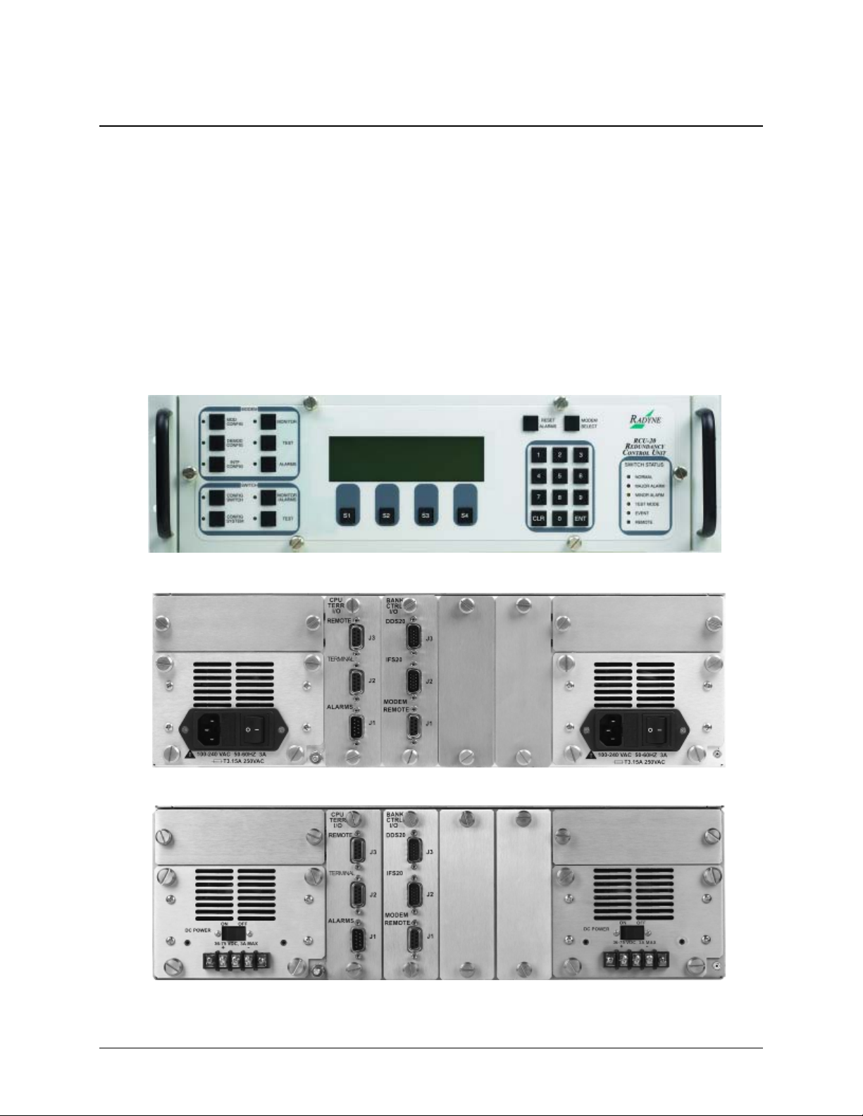
1.3.1 RCU20 Redundancy Control Unit
Front panel controls and indicators provide for auto/manual configuration, as well as display of
online/off line status information for all modems in the Redundancy configuration.
Figure 1-1 RCU20 Redundancy Control Unit – Front Panel
Figure 1-2 RCU20 Redundancy Control Unit – Back Panel (AC Powered)
Figure 1-3 RCU20 Redundancy Control Unit – Back Panel (DC Powered)
1–2
Page 25

RCS20 M:N Redundancy Switch Rev. 14
Introduction MN-RCS20
1.3.2 Digital Data Switch (DDS20) Configurations
The DDS20 provides all of the data interconnections between the online and backup modems.
The DDS20 also provides buffering of terrestrial data signals to backup modulators allowing
‘hot-standby’ modes of operation. The DDS20 receives control and DC power through an
interconnecting cable from the RCU20. Terrestrial interface options for the DDS20 include the
following options:
• Universal Interface: RS-449, V.35, RS-232, IDR & IBS Alarms
• ASI Interface: BNC Female
• G.703 Interface: Unbalanced T1, E1, T2, E2, T3, E3, STS-1
• Ethernet: RJ45 - 10/100/1000 Base-T.
The DDS20 is available in the following three configurations:
• Universal DDS20
• DDS20-ASI-M or DDS20-G.703-M (Modulator only)
• DDS20-ASI-D or DDS20-G.703-D (Demodulator only)
1–3
Page 26
RCS20 M:N Redundancy Switch Rev. 14
Introduction MN-RCS20
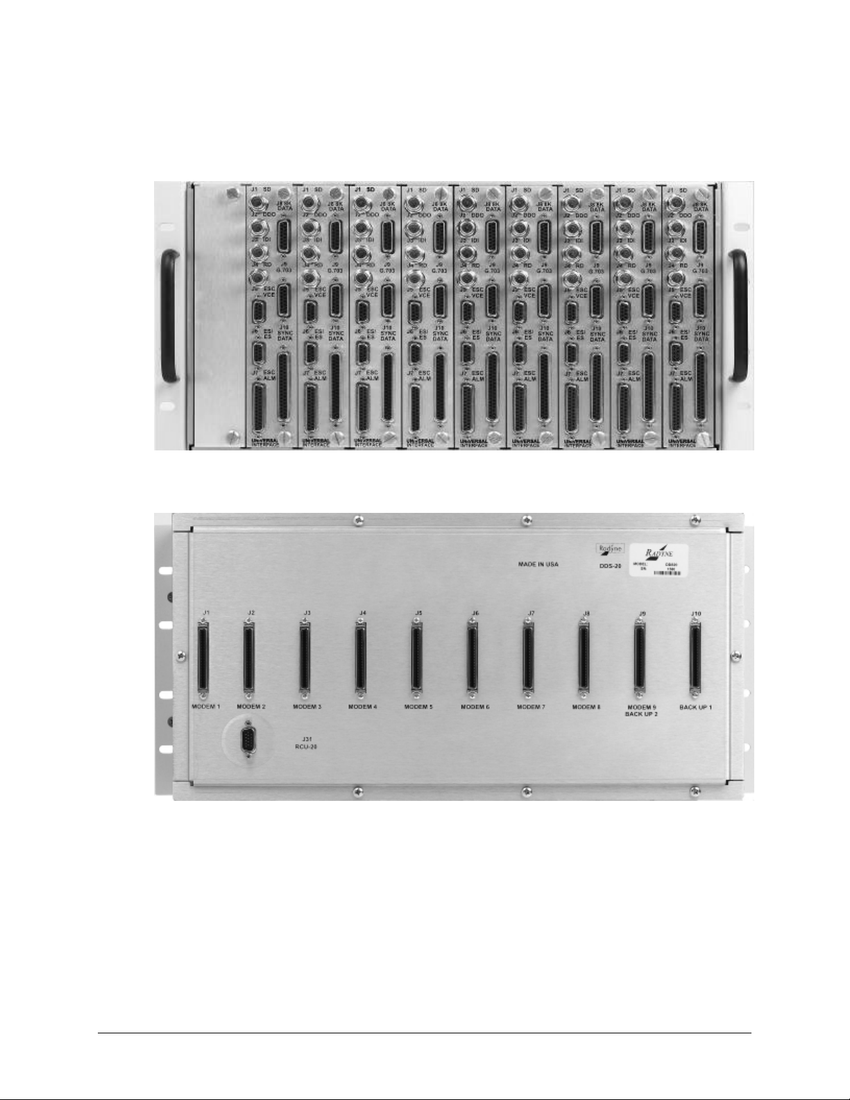
1.3.2.1 Universal DDS20
The Universal DDS20 has nine available slots supporting up to a 1:9 or 2:8 configuration.
Figure 1-4 Universal DDS20 Digital Data Switch – Front Panel
Figure 1-5 Universal DDS20 Digital Data Switch – Back Panel
1–4
Page 27
RCS20 M:N Redundancy Switch Rev. 14
Introduction MN-RCS20
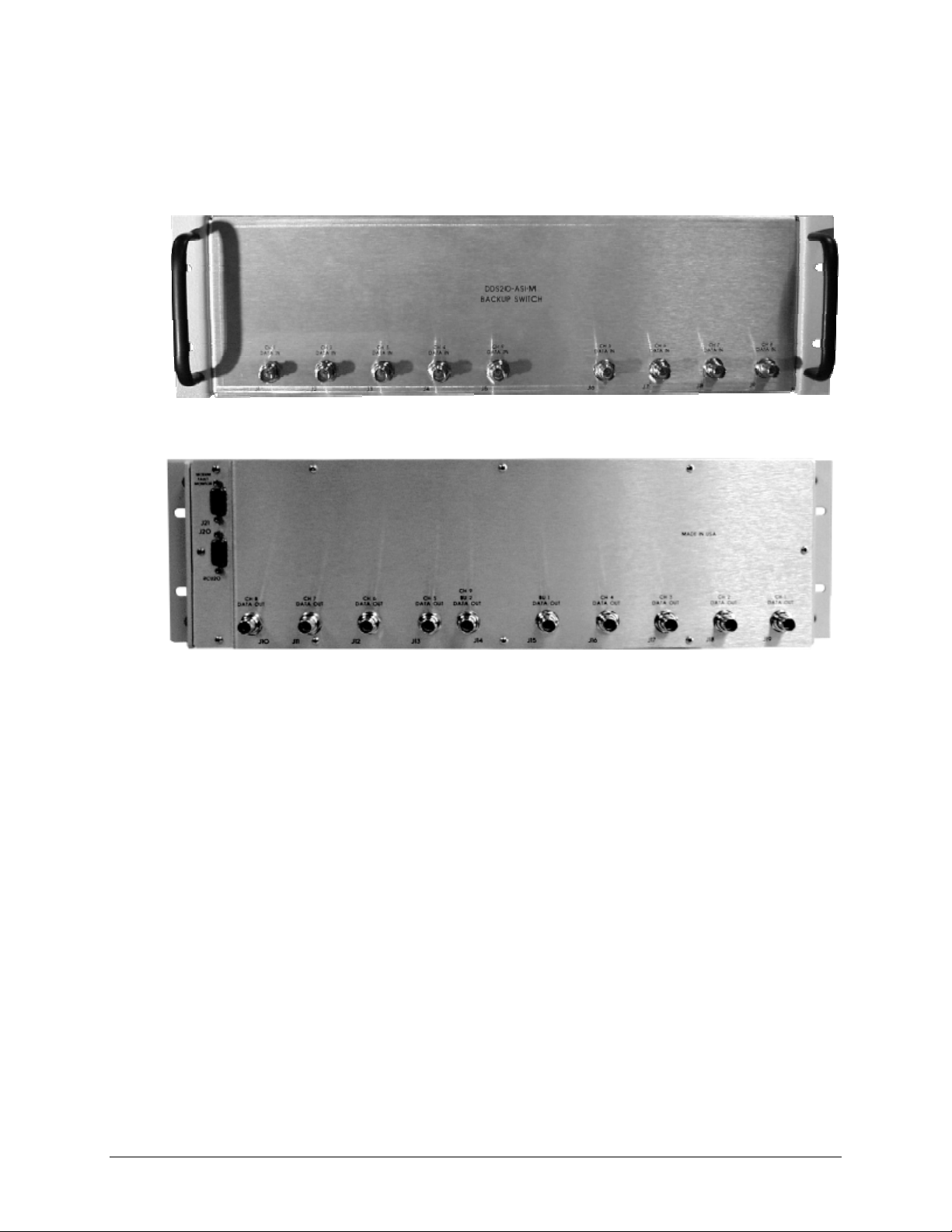
1.3.2.2 DDS20-ASI-M or DDS20-G703-M (Modulator-only)
The DDS20-ASI-M or G703-M is a modulator-only configuration.
Figure 1-6 DDS20 ASI or G703-M Digital Data Switch – Front Panel
Figure 1-7 DDS20 ASI or G703-M Digital Data Switch – Back Panel
1–5
Page 28
RCS20 M:N Redundancy Switch Rev. 14
Introduction MN-RCS20
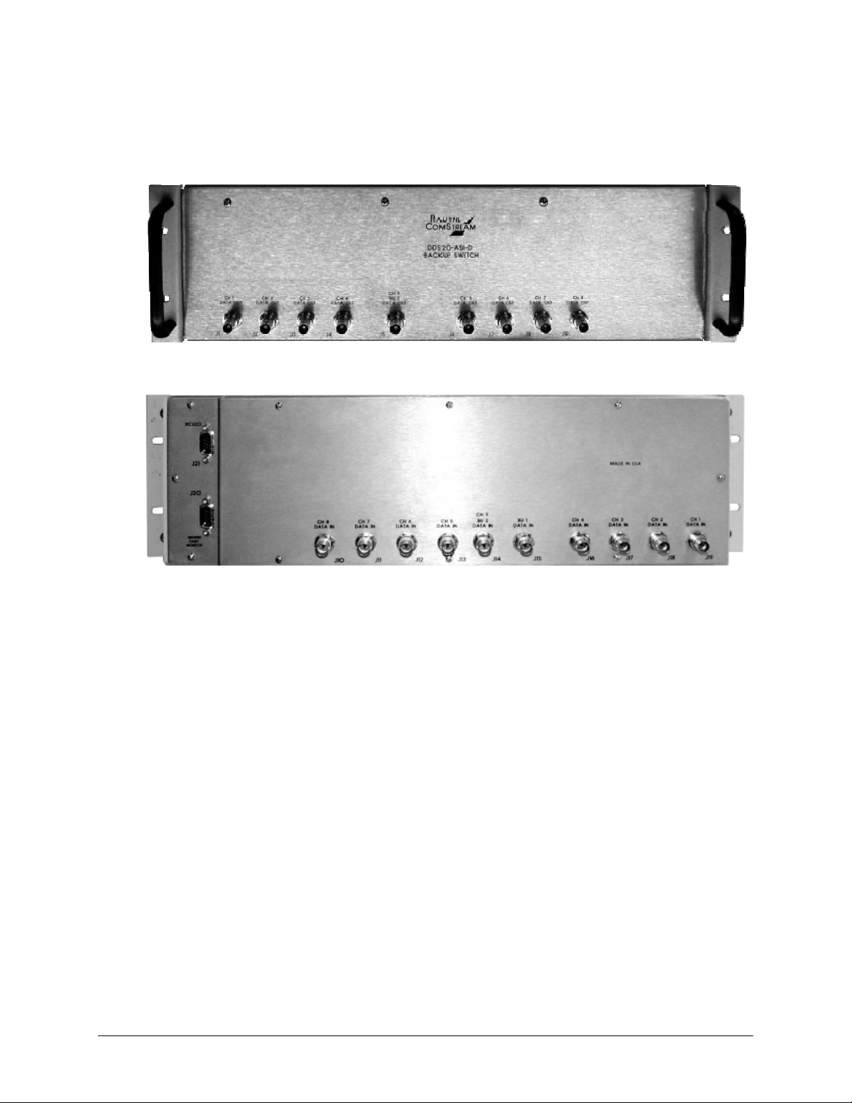
1.3.2.3 DDS20-ASI or DDS20-G.703-D (Demodulator-only)
The DDS20-ASI-D or DDS20-G.703-D is a demodulator-only configuration.
Figure 1-8 DDS20-ASI-D or DDS20-G.703-D Digital Data Switch – Front Panel
Figure 1-9 DDS20-ASI-D or DDS20-G.703-D Digital Data Switch – Back Panel
1–6
Page 29
RCS20 M:N Redundancy Switch Rev. 14
Introduction MN-RCS20
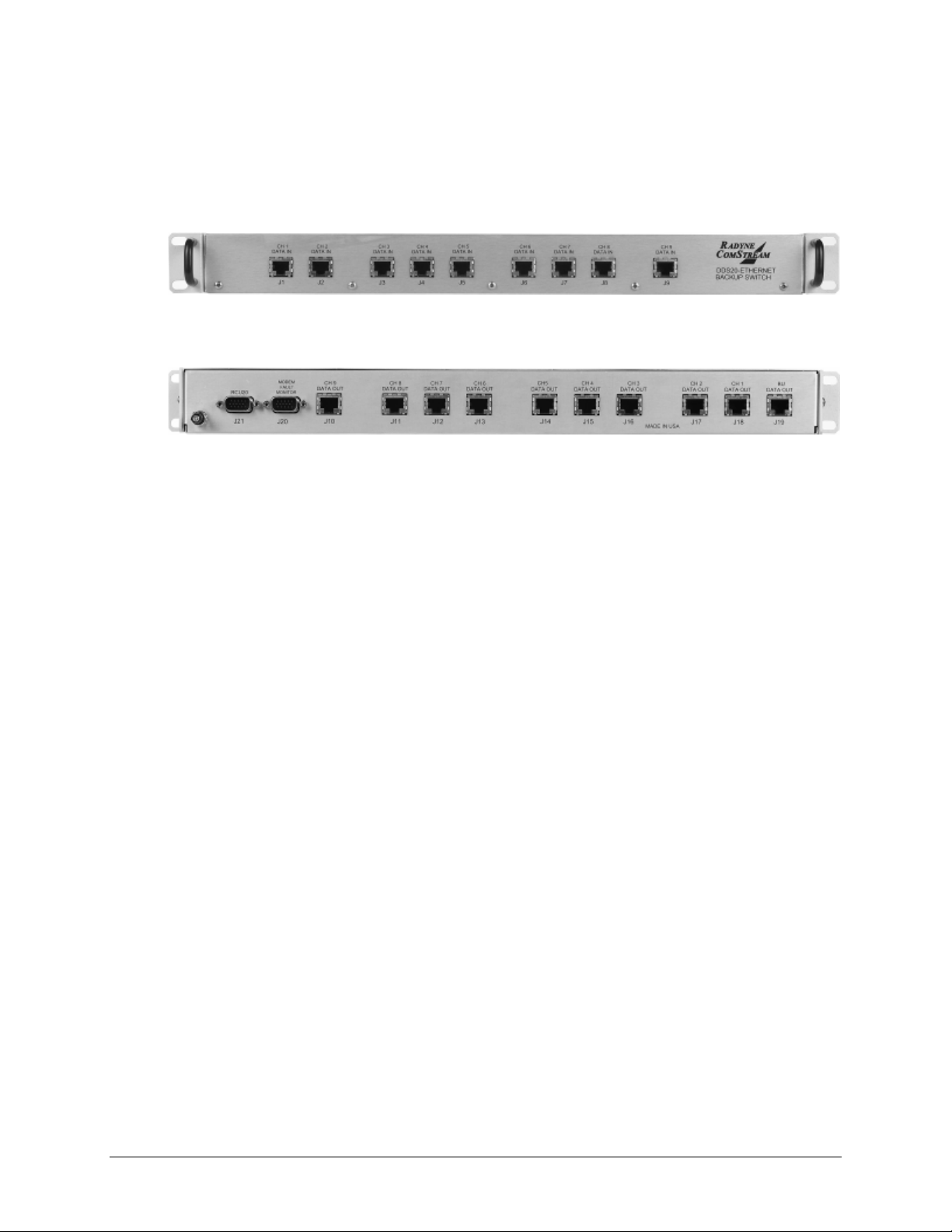
1.3.2.4 DDS20-GigE (10/100/1000 Gigabit Ethernet) Backup Switch
The DDS20-GigE Backup Switch configuration supports the DMD20, DMD50, DM240 and
DD240 products. The Ethernet switch can support up to a 1:9 system.
Figure 1-10 DDS20-GigE Backup Switch – Front Panel
Figure 1-11 DDS20-GigE Backup Switch – Back Panel
1–7
Page 30
RCS20 M:N Redundancy Switch Rev. 14
Introduction MN-RCS20
1.3.3 Intermediate Frequency Switch (IFS20) Configurations
The IFS20 Intermediate Frequency Switch interfaces the IF signals of the modems with the Earth
Station IF system and provides backup switching. The RCU20 can be configured with or without
the IFS20. When the system does not require independent uplink and downlink ports, then the
RCU20 will monitor the status of the primary modem and ensure backup when a primary modem
faults.
When the system is configured with an IFS20, it will provide all of the switching relays and
optional signal splitters that are necessary to connect any combination of up to nine Modulators
and Demodulators to nine independent uplink and nine independent downlink transponders. The
IFS20 receives control and DC power through an interconnecting cable from the RCU20. The
IFS20 is available in the following three configurations:
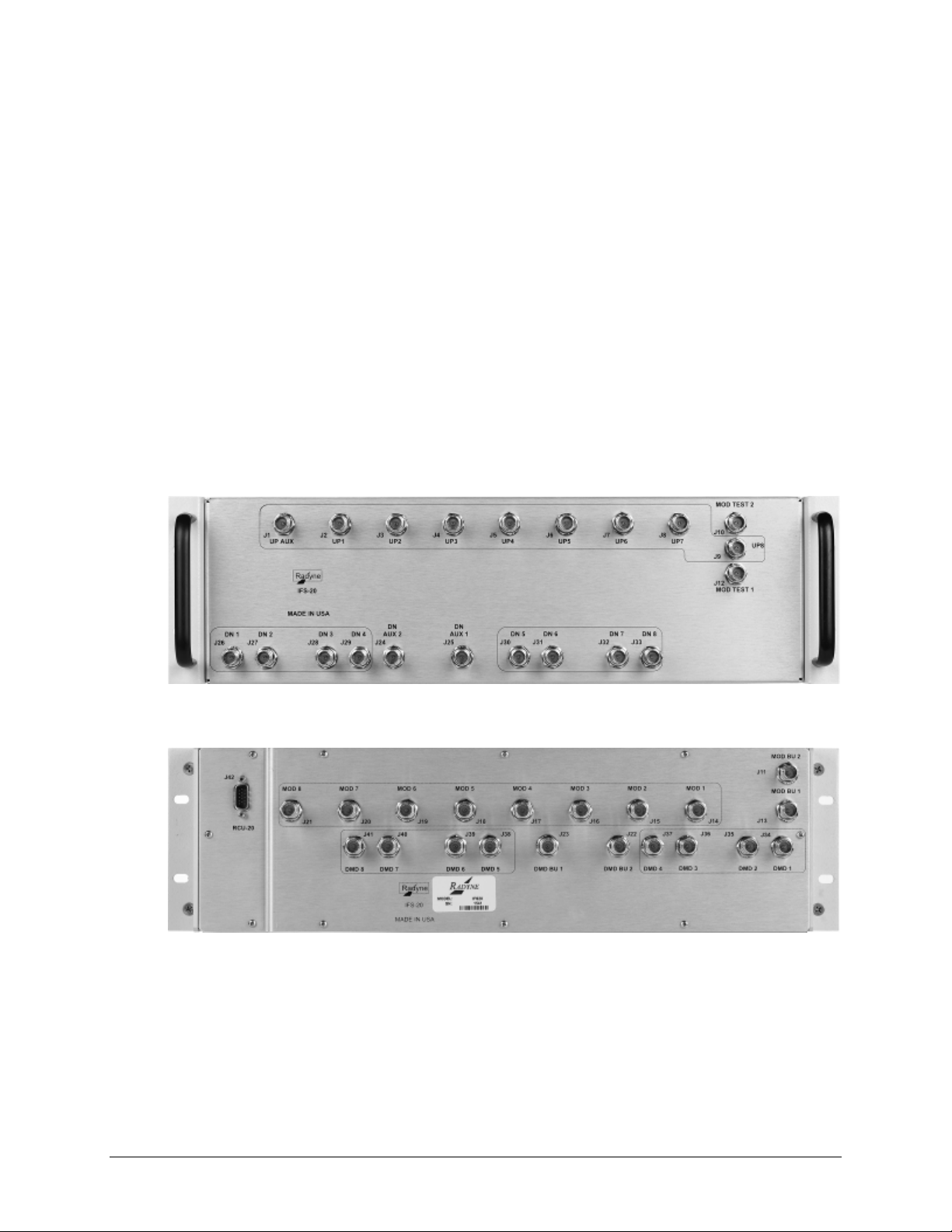
1.3.3.1 70/140 IFS20
The IFS20 configuration is used for 70/140 MHz.
Figure 1-12 70/140 IFS20 Intermediate Frequency Switch – Front Panel
Figure 1-13 70/140 IFS20 Intermediate Frequency Switch – Back Panel
1–8
Page 31

RCS20 M:N Redundancy Switch Rev. 14
Introduction MN-RCS20
1.3.3.2 L-Band IFS20 (Transmit Only)
This IFS20 configuration is used for L-Band transmit only systems.
Figure 1-14 L-Band (Transmit Only) IFS20 Intermediate Frequency Switch – Front Panel
Figure 1-15 L-Band (Transmit Only) IFS20 Intermediate Frequency Switch – Back Panel
1–9
Page 32

RCS20 M:N Redundancy Switch Rev. 14
Introduction MN-RCS20
1.3.3.3 L-Band IFS20 (Transmit & Receive)
This IFS20 configuration is used for L-Band transmit and receive systems.
Figure 1-16 L-Band (Transmit & Receive) IFS20 Intermediate Frequency Switch – Front Panel
Figure 1-17 L-Band (Transmit & Receive) IFS20 Intermediate Frequency Switch – Back Panel
1–10
Page 33

2.1 Overview
This chapter provides unpacking instructions, and instructions for installing an RCS20 M:N
Redundancy Switch into a Satellite Modem system with cabling configurations for up to nine
channels and nine transponders.
Chapter 2. Installation
The RCS20 organizes the modems connected to the switch according to
satellite communications channels. These channels are labeled on the
DDS20 and IFS20 panels, and are defined as follows:
Channel 0 - Backup 1
Channel 1 - Modem 1
Channel 2 - Modem 2
Channel 3 - Modem 3
Channel 4 - Modem 4
Channel 5 - Modem 5
Channel 6 - Modem 6
Channel 7 - Modem 7
Channel 8 - Modem 8
Channel 9 - Modem 9/Backup 2
2–1
Page 34

RCS20 M:N Redundancy Switch Rev. 14
Installation MN-RCS20
2.2 Unpacking the Unit
There are no user-serviceable parts or configuration settings located inside
the RCS20, DDS20, or IFS20 Chassis. There is a potential shock hazard
internally at the power supply module. DO NOT open any of these Chassis
under any circumstances.
The RCS20 M:N Redundancy Switch was carefully packaged to avoid damage and should arrive
complete with the following items for proper installation:
• RCS20 Redundancy Control Unit
• IFS20 70/140, L-Band Tx or L-Band Rx-Tx
• DDS20 Digital Data Switch, Ethernet Switch, ASI-M or ASI-D
• 2 ea. AC Power Cords
• 2 ea. Bank Control 15-Pin HD Sub-Cables
• M:N Switch System Test Data Sheet
• M:N Switch to Modem Cable(s) for Backup Modulator and Demodulator
• Test I/O Mating Connector
• Optional 1:N Switch to Modem, I/O and Coaxial Cables for Modems 1 – 9
• Optional Modem bypass cable(s) for Modems 1 – 9
Any cables ordered in addition to those listed above may arrive separately.
2.2.1 Test Data Sheet
Each RCS20 M:N Redundancy Switch system is shipped with a Test Data Sheet. This report
contains information on the results of the Switch quality control testing. The report also includes
information pertaining to the system settings that were made at the factory. It is recommended
that the customer/user save this report for future reference.
2–2
Page 35

RCS20 M:N Redundancy Switch Rev. 14
Installation MN-RCS20
2.3 Removal and Assembly
Carefully unpack the unit and ensure that all of the above items are in the carton. If the available
AC mains power at the installation site requires a different cordset from those included in the
package, then a suitable and approved cordset (for the country where the equipment is to be
installed) will be required before proceeding with the installation.
Should the Power Cable/AC Connector be of the wrong type for the installation, either the cable
or the power connector end should be replaced. The power supply itself is designed for universal
AC application. See specifications for appropriate voltages and currents.
2.4 Mounting Considerat ions
Adequate site planning and preparation simplifies the installation process and results in a more
reliable system. The user should ensure that the site has adequate electrical power. The power
sources should be properly grounded and as free as possible from electrical interference. If a
redundant configuration is to be used, then each power cord on the RCS20 must be plugged into
its own separate power circuit. Each circuit must have its own independent circuit breaker.
Grounding is achieved automatically when the three-prong power plug is inserted into a power
receptacle. Verify by testing that there is no voltage present between the chassis of the Switch and
the power line ground.
The protective ground must not be bypassed with a three prong to two-prong
adapter or defeated in any way. Defeating the ground may result in operator
injury or damage to the system.
When mounting The RCS20 in an equipment rack, adequate ventilation must be provided. The
ambient temperature in the rack should preferably be between 10° and 35°C, and held constant
for best equipment operation. The air available to the rack should be clean and relatively dry. The
units should not be placed immediately above a high-heat or EMF Generator to ensure the output
signal integrity and proper receive operation.
The RCS20 is designed so that it can be mounted in a standard 19-inch rack. The RCS20 is 5¼”,
3 Rack Units (3RU) high and must be mounted on the front of a rack with the front panel facing
forward
The DDS20 is 8¾” (5RU) high and is preferably mounted at the top of a rack unit with the
Terrestrial Interface connectors available at the top of the rack and the modem connections
available at the at the bottom of the DDU20 in the interior of the rack. The DDS20 may also be
mounted at the rear of a rack with the Terrestrial Interface connectors available at the rear of the
rack and the modem connections available in the interior of the rack.
The IFS20A is also 8¾” (5 RU) high and is designed to be mounted at the rear of a rack with the
Up/Downconverter interface connections facing to the rear of the rack with the modem IF
connections available in the interior of the rack. The IFS20A may also be mounted in the top of a
rack with the Up/Downconverter interface connections available at the top of the rack and the
modem IF connections available inside the rack.
2–3
Page 36

RCS20 M:N Redundancy Switch Rev. 14
Installation MN-RCS20
To allow for the easy installation of cables and adequate air circulation through the units, a
minimum of six inches of clearance must be provided at the sides and rear of the units. In
addition, the RCS20 requires a minimum of 1¾” (1 RU) of clearance on top of the unit.
If the Switch is mounted on slide mounts, the cables must be of sufficient length to allow the
units to be pulled forward on the mounts.
Do not mount the RCS20 in an unprotected outdoor location where there is direct contact with
rain, snow, wind or sun. The only tools required for rack mounting the RCS20 are four (4)
customer supplied rack-mounting screws and the appropriate screwdriver. Rack mounting
brackets are an integral part of the front bezel of the unit and are not removable.
2.5 Storage
It is recommended that the unit be stored in its original sealed packing. The unit should be stored
in a dry location where the temperature is stable, away from direct contact with rain, snow, wind,
sun, or anything that may cause damage.
2.6 Connecting the RCS20
1. Dangerous AC voltages exist inside of the RCS20 when either one of
the AC Plug-in Switch Modules are enabled or plugged in. Do not
remove cover when AC power is applied. Remove power cord from AC
modules if top cover needs to be removed.
See Chapter 5 for additional information on replacing the AC/DC
Plug-in Modules.
2. The RCU20 MUST
bank control I/O OR
CA3429 cables. Failure to do so can result in damage to the bank
control I/O and cause loss of redundancy in the system.
be powered down when installing / removing the
when cabling up to the IFS20 or DDS20 with the
2.7 System Cabling Conf igurati on
See Appendix B for the cabling configurations between the RCS20 and its various companion
products. The following figures are provided to illustrate the proper placement of the cables:
2.8 Modem Checkout and Initial Power-Up
The following descriptions assume that the RCS20 is installed in a suitable location with AC
power applied to both slide out power supplies. Before initial power-up of the RCS20, the IFS20
and DDS20 must be connected to the RCU20 via the supplied 15-Pin High-Density Female ‘D’
Connection Cables.
2–4
Page 37

RCS20 M:N Redundancy Switch Rev. 14
Installation MN-RCS20
apply power to the slide out power supply modules unless they are
Never
firmly seated in the RCU20, as there is a potential shock hazard at the
AC/DC Converter within the module
Turn the unit on by switching both AC power switches (located above the power entry connectors
at the rear of the RCU20) to the on position. At power-up, the switch processor will perform a
self-diagnostic before beginning the primary monitor/control program. If a failure is detected
during the power-up tests, the Major Alarm LED will illuminate. If there is no failure, there will
be no indication on the front panel.
The initial field checkout of the switch can either be accomplished from the front panel or from a
terminal connected to the Terminal Port. Using a terminal has the advantage of providing full
screen access to all of the switch parameters, but requires a separate terminal or computer with
terminal emulation software. If a terminal is used, the Terminal Port baud rate must first be set
from the front panel.
2–5
Page 38

RCS20 M:N Redundancy Switch Rev. 14
Installation MN-RCS20
Notes:
2–6
Page 39

Chapter 3. Theory of Operation
3.1 Overview
This chapter provides additional basic information on the RCU20, DDS20, and IFS20 hardware
and internal operation.
3.2 RCU20 Major Assemblies
The RCU20 Redundancy Control Unit contains the modules that control and monitor the
operation of the M:N Switch System. The RCU20 is composed of the following major assemblies
and components:
• Central Processor Unit (CPU) Board
• Front Panel Board
• Controller Interface Module
• Clock Distribution Module (optional)
• Redundant Power Supplies
• Ethernet Module (optional)
• Bank Control Module
3.2.1 Central Processing Unit (CPU) Board
The Central Processor Unit (CPU) Board contains the M:N Switch intelligence and memory
circuitry. The on-board microprocessor is an MC68302, which has a 24-bit address bus and a 16bit data bus. The microprocessor controls and coordinates all major functions of the Switch and
performs all necessary calculations. The non-volatile system memory on the board stores the
switching parameter settings for each Modem Channel. Control and data signals are routed to the
appropriate devices in the system through various latches and transceivers that are controlled by
the microprocessor.
3–1
Page 40

RCS20 M:N Redundancy Switch Rev. 14
Theory of Operation MN-RCS20
3.2.2 Front Panel
Front panel controls and indicators provide for auto/manual configuration, as well as display of
online/off line status information for all modems in the Redundancy configuration. See Section
4.1
3.2.3 Controller Interface Module
The controller interface module (CPU TERR I/O) provides ports for external monitoring and
control. See Section 5.2.3.2.
3.2.4 Clock Distribution Module (Optional)
Consult factory for availability. See Section 5.2.3.1.
3.2.5 Redundant Power Supplies
The M:N Switch comes equipped with two fully redundant internal power supplies (PS1 and PS2)
that supply DC voltage to the system. Each supply is fully independent of the other, including
their source of AC power and fusing.
The Switch can remain fully operational as long as it is supplied with a source of voltage from
either power supply. Only if the voltage output failed on both supplies would the Switch become
inoperative. PS1 and PS2 are located one on either side of the RCS20.
3.2.6 Ethernet Module (Optional)
Consult factory for availability.
3.2.7 Bank Control Module
The Bank Control Module provides connection to auxiliary equipment. See Section 5.2.3.3.
3.2.8 RCU20 Back Panel
Tthe RCS20 contains the plug-in slots for the Interface Control Module, the Clock Distribution
Modules, Bank Control Modules and Ethernet modules. Also contained in the back panel are the
two AC fuses and power receptacles.
3.3 IFS20 Major Assemblies
The IFS20 IF Switch interfaces the IF signals of the Modems with the earth station IF system and
provides backup switching. The unit provides all of the switching relays, signal combiners and
splitters, terminations and interconnecting cables that are necessary to connect any combination
of up to eight Modulators and Demodulators to eight independent uplink and eight independent
downlink transponders.
3–2
Page 41

RCS20 M:N Redundancy Switch Rev. 14
Theory of Operation MN-RCS20
The IFS20 has no internal power supply. It receives its DC power from the RCU20 through the
cable that connects to J35. The IFS20 internal connectors are SMB-type. The major parts of the
IFS20 are:
• IF Switch Relays (eight uplink, and eight downlink).
• Back Panel/Front Panel
3.3.1 IF Switch Relays
The IFS20 contains 16 IF Switch Relays; eight uplink and eight downlink. The relays switch the
IF signals to the Backup units. The signals to each downlink relay pass through a splitter with a
loss of about 3.5 dB (including the loss due to energy splitting).
3.3.2 IFS20 Back Panel/Front Panel
See Section 5.3.
3.4 DDS20 Major Assemblies
The DDS20 Data Switch provides terrestrial interface and data signal switching for up to nine
independent pairs of Modulators and Demodulators. There are two parallel and independent
backup busses allowing any of the eight on-line Modulators and Demodulators to be switched to
either of the backup Modulators or Demodulators. The DDS20 has no internal power supply, it
receives DC power from the RCU20 through the cable that connects at J31.
3.4.1 Motherboard
The DDS20 Motherboard contains the modem connectors and backup busses.
3.4.2 Slide-In Data Switch Interface Modules
The DDS20 contains one slide-in data switch interface module for each prime modem, containing
terrestrial interface connectors and data switch relays.
3.4.3 Housing
The housing contains the card guides and mounting ears for the motherboard.
3–3
Page 42

RCS20 M:N Redundancy Switch Rev. 14
Theory of Operation MN-RCS20
3.4.4 DDS20 Back Panel
The DDS20 back panel contains the electrical connections.
3.5 RCS20 Channel Definitions
The RCS20 organized the modems connected to the switch according to satellite communications
channels. These channels are labeled on the DDS20 and IFS20 panels, and are defined as follows:
Channel 0 - Backup 1
Channel 1 - Modem 1
Channel 2 - Modem 2
Channel 3 - Modem 3
Channel 4 - Modem 4
Channel 5 - Modem 5
Channel 6 - Modem 6
Channel 7 - Modem 7
Channel 8 - Modem 8
Channel 9 - Modem 9/Backup 2
3–4
Page 43

Chapter 4. User Interfaces
4.1 Operating Procedures
Operation of the RCS20 consists of controlling the unit operating parameters and monitoring
status and responses via one of the following control interfaces:
• Front Panel Interface
• Remote Port Interface
• Terminal Interface
Any of these methods may be used separately or together to monitor and control the RCS20.
4–1
Page 44

RCS20 M:N Redundancy Switch Rev. 14
User Interfaces MN-RCS20
4.2 Front Panel Interface
Figure 4-1. Front Panel Interface
The RSC20 front panel (Figure 4-1) allows complete control and monitoring of all Modem and
Switch parameters and functions via a k
eypad, LCD display and Modem and Switch status LEDs.
Table 4-1. Front Panel Interface Feature Descriptions
Feature
No.
1 MODEM
2 (---)
3
4
5
6 (---)
7 (---)
8 SWITCH
Label Description
Modem Control. This group of keys is used to control the modems that
are connected to the RCS20 from the RCS20 front panel. This feature
is presently not implemented for the RCS20
LCD Front Panel Display. This is the 8 lines by 40 characters Liquid
Crystal Display, used to communicate with the RCS20.
RESET
ALARMS
MODEM
SELECT
SWITCH
STATUS
Reset Alarms. This key resets all RCS20 current and latched major
and minor alarms.
Select Current Modem. This key selects which modem is currently
being controlled by the Modem group of keys. This feature is presently
not implemented for the RCS20.
Switch Status LEDs. Refer to Section 4.1.5 for a description of these
LEDs.
Numeric Keypad. This group of keys is used to enter numeric
parameters for the RCS20 and connected modems.
Soft keys. This group of keys is used for various functions as
described by the label shown above each key on the bottom line of the
LCD Display.
Switch Control. This group of keys is used to control the RCS20 and
decide which menu tree is displayed on the front panel.
4–2
Page 45

RCS20 M:N Redundancy Switch Rev. 14
User Interfaces MN-RCS20
4.2.1 Modem Control Keys
The following keys, when pressed, control the modems that are connected to the RCS20:
(Currently this feature is not implemented on the RCS20)
4.2.1.1 MODEM MOD CONFIG
Pressing this key brings up a series of menus on the LCD that allow control of the currently
selected modulator that is connected to the RCS20. The currently selected modulator and
demodulator can be changed by pressing the MODEM SELECT key. This feature is presently not
implemented on the RCS20
4.2.1.2 MODEM DEMOD CONFIG
Pressing this key brings up a series of menus on the LCD that allow control of the currently
selected demodulator that is connected to the RCS20. The currently selected modulator and
demodulator can be changed by pressing the MODEM SELECT key. This feature is presently not
implemented on the RCS20
4.2.1.3 MODEM INTFC CONFIG
Pressing this key brings up a series of menus on the LCD that allow control of the terrestrial
interface for the currently selected modem. The currently selected modem can be change by
pressing the MODEM SELECT key. This feature is presently not implemented on the RCS20.
4.2.1.4 MODEM MONITOR
Pressing this key brings up a series of menus on the LCD that allow the monitoring of status
parameters for modems connected to the RCS20. This feature is presently not implemented on the
RCS20.
4.2.1.5 MODEM TEST
Pressing this key brings up a series of menus on the LCD that allow testing of the modems
connected to the RCS20. This feature is presently not implemented on the RCS20.
4.2.1.6 MODEM ALARMS
Pressing this key brings up a series of menus on the LCD that allow monitoring of alarms for the
modems connected to the RCS20. This feature is presently not implemented on the RCS20.
4.2.2 LCD Front Panel Display
The front panel display is an 8 line by 40-character LCD display. The display is lighted and the
brightness can be set to increase when the front panel is currently in use. The LCD display
automatically dims after a period of inactivity.
The display has two distinct areas showing current information. The bottom row of the display
shows the functions of each of the four soft keys (labeled ‘S1’, ‘S2’, ‘S3’, and ‘S4’ in Figure 3-1).
If a soft key provides a function, then that function will be displayed just above the corresponding
key. If no function is displayed above a soft key, then there is no function associated with that
key, and pressing it will have no effect. The rest of the display shows current parameter and status
information. The LCD display is a window into a large matrix of switch and modem parameters
that can monitored and changed from the front panel.
4–3
Page 46

RCS20 M:N Redundancy Switch Rev. 14
User Interfaces MN-RCS20
The display backlight will extinguish after a programmable delay if no there is no keyboard
activity. The backlight will then turn on whenever a key is pressed. The backlight delay can be
adjusted from the menu.
4.2.3 Reset Alarms Key
This key resets all RCS20 current and latched major and minor alarms.
4.2.4 Module Select Key
This key selects which modem is currently being controlled by the Modem group of keys. This
feature is presently not implemented for the RCS20
4.2.5 Switch Status LEDs
Refer to Table 4-2 for the description and colors of the Switch Status LEDs. 4.2.1.6 MODEM
ALARMS.
Table 4-2. Switch Status LED Function
LED Color Description
Normal Green Indicates that the unit is currently under power.
Major Alarm Red
Minor Alarm Yellow
Minor Alarm Flashing Yellow
Test Mode Yellow Indicates that the switch is performing one of the system tests.
Event Yellow
Event Flashing Yellow Indicates a prime modem is currently being backed-up.
Remote Green
4.2.6 Numeric Keypad
This group of keys is used to perform various functions for the RCS20 and connected modems.
Table 4-3 describes the function of these keys.
Key Description
ENTER
CLEAR
Numeric keys 0-9 Used to edit numeric parameters.
Indicates that at least one satellite channel did not receive
Redundancy protection and is off-line.
Indicates that a Redundancy warning exists and the RCS20
may not be providing Redundancy protection.
Indicates a prime modem configuration. The configuration
change should be taught.
Indicates that a condition of system event as occurred that the
RCS20 has stored in memory. The events may be viewed
from the Front Panel or from the Terminal port.
Indicates that the unit is set to respond from either the
Terminal port or the Remote M&C port
Table 4-3. N
Loads edited values into memory and advances to next screen in the menu
tree.
Aborts loading values into memory and advances to the previous screen in
the menu tree.
umeric Keypad Function
4–4
Page 47

RCS20 M:N Redundancy Switch Rev. 14
User Interfaces MN-RCS20
4.2.7 Soft Keys (S1 - S4)
This group of keys is used for various functions as described by the label shown above each key
on the bottom line of the LCD Display.
Table 4-4. Soft Key Function
Key Description
soft key
(‘NEXT’)
soft key
(‘PREVIOUS’)
Aborts loading values into memory and advances to the next screen in the menu
tree.
Aborts loading values into memory and advances to the previous screen in the
menu tree.
4.2.8 Switch Control Keys
The following keys, when pressed, control the RCS20 and decide which of the menu trees is
displayed on the LCD front panel display.
4.2.8.1 SWITCH CONFIG SWITCH
Pressing this key brings up a series of menus on the LCD that allow control of the RCS20 switch
configuration parameters.
4.2.8.2 SWITCH CONFIG SYSTEM
Pressing this key brings up a series of menus on the LCD that allow control of the RCS20 system,
M&C, and communication parameters.
4.2.8.3 SWITCH MONITOR/ALARMS
Pressing this key brings up a series of menus on the LCD that allow monitoring of major and
minor alarms and control of alarm masking for the RCS20.
4.2.8.4 SWITCH TEST
Pressing this key brings up a series of menus on the LCD that allow testing of the RCS20
configurations and connections.
4.2.9 Basic Front Panel Controls
The following functions may be performed from the front panel:
• the parameters on the screen can be edited
• the next screen in the menu tree can be displayed
• the previous screen in the menu tree can be displayed
4.2.9.1 Changing parameters from the Front Panel
Whenever there is a parameter that can be changed or edited from the front panel, the first
character of the parameter value will highlight with a blinking box. This box is called the cursor,
and the cursor defines what parameter is currently being edited. If there are several parameters
on one screen, two of the soft keys will be labeled Å and Æ. These keys are used to move the
cursor from one parameter to the next, and therefore any of the configuration parameters
displayed on the screen can be edited. The left arrow ( Å ) moves the cursor to the left, and the
right arrow ( Æ ) moves the cursor to the right. If the cursor is at the beginning or end of a row
containing several parameters, the cursor will wrap to the opposite side of the display.
4–5
Page 48

RCS20 M:N Redundancy Switch Rev. 14
User Interfaces MN-RCS20
Editing a configuration parameter value is accomplished in one of several ways. If the parameter
is numerical, the desired value should be entered from the numeric keys. Occasionally, the
numeric values can be incremented and decremented by pressing soft keys labeled ‘UP’ and
‘DOWN’ respectively. In either case, when all of the numerical parameters have been edited to
the desired values, pressing the ENTER key will execute a load of the parameters into memory,
and then advance to the next screen in the menu tree. Pressing the CLEAR key will not execute a
load of parameters into memory (the original parameter values before editing will be retained),
and then advance to the previous screen in the menu tree.
If a parameter has a non-numeric value, the allowed values for that parameter can be edited by
pressing soft keys with the desired values. In cases where there are multiple parameters shown on
a screen, the values are edited with the soft keys and loaded by pressing the ENTER key, which
also advances to the next screen in the menu tree. Pressing the soft key labeled ‘NEXT’ or
‘PREVIOUS’ will abort loading the parameters into memory, and advance to the appropriate
screen. In cases where there is a single parameter shown on a screen, pressing the soft key labeled
with the desired value will immediately load the parameter into memory. In this case, the
parameter load can be aborted by pressing the CLEAR key, which will return to the previous
screen, or by pressing the soft key labeled ‘NEXT’, which will advance to the next screen in the
menu tree.
4.2.9.2 Moving to the Next Screen in a Menu Tree
If the user desires to advance to the next screen in the menu tree, the soft key labeled ‘NEXT’
should be pressed. Some submenu screens can only return to a previous screen, in this case a soft
key will be labeled ‘RETURN’. In either case, if any numerical parameters are being edited, the
values will not be loaded into memory. When the last screen of a menu tree is reached, advancing
to the next screen will wrap to the first screen of the menu tree.
4.2.9.3 Moving to the Previous Screen in a Menu Tree
If the user desires to return to the previous screen from a Subscreen in the menu tree, the CLEAR
key should be pressed. If any numerical parameters are being edited, the values will not be loaded
into memory. If the clear key is pressed while the first screen of a menu tree is displayed, the
previous screen will wrap to the last screen in the menu tree.
4–6
Page 49

RCS20 M:N Redundancy Switch Rev. 14
User Interfaces MN-RCS20
4.3 Front Panel Screens
There are four menu trees used to control the RCS20:
• CONFIG SWITCH
• CONFIG SYSTEM
• MONITOR/ALARMS
• TEST
These menu trees and their functions are discussed in the subsections that follow.
The screens as depicted in the subsections that follow are
representations. Your screens may vary slightly.
4–7
Page 50

RCS20 M:N Redundancy Switch Rev. 14
User Interfaces MN-RCS20
4.3.1 CONFIG SWITCH Menu Tree
4.3.1.1 MODEM CHANNEL CONNECTIONS
MODEM CHANNEL CONNECTIONS
BACKUP : B2 B1
MODEM : 1 2 3 4 5 6 7 8 9 0
CONNECT:md md md md md md md md md md
<--- ---> TOG MODE NEXT
This screen allows the user to assign connections to the channels. The RCS20 must be
programmed with satellite channel numbers used for redundancy protection. Channel 0 is the
dedicated backup, and Channel 9 may either be prime or backup. Channels 1 to 8 are dedicated
backups. These connections may be any of the following:
• m - modulator
• d - demodulator
• md - modulator/demodulator
• none - No Connection
Programming steps:
1. Press Å or Æ to move the blinking cursor to the channel to be programmed
2. Press <TOG MODE> to switch through the choices above.
3. Press <CLR> or <NEXT> to abort programming (no switch parameters will be changed).
4. Press <ENT> to load the information on the screen into the switch parameter table.
Key Label Function
S1
S2
S3
Å
Æ
TOG
MODE
S4 NEXT Press to cycle to the next screen.
Numeric
Keypad
---
Press to move the blinking cursor to the left. Used to select the channel
connection.
Press to move the blinking cursor to the left. Used to select the channel
connection.
Used to toggle through the choices above. Multiple connections may be
entered.
Press <CLR> or <NEXT> to abort programming (no switch parameters
will be changed).
Press <ENT> to load the information on the screen into the switch
parameter table.
4–8
Page 51

RCS20 M:N Redundancy Switch Rev. 14
User Interfaces MN-RCS20
4.3.1.2 MODEM ADDRESSES
MODEM ADDRESSES USE KEYPAD
B2 B1
1 2 3 4 5 6 7 8 9 0
101 102 103 104 105 106 107 108 109 110
<--- ---> NEXT
This screen allows the user to program the remote addresses of each modem connected to the
redundancy system. All addresses must be in the range of 32 to 255 decimal. All entries on this
screen are in decimal. Multiple addresses may be programmed.
Programming steps:
1. Press Å or Æ to move the blinking cursor to the channel to be programmed.
2. Use the numeric keypad to enter the address for the channel at the cursor
3. Enter an address for each modem connected to the redundancy system at the blinking cursor.
Addresses for channels that do not have a modem connected will be ignored.
4. Press <CLR> or <NEXT> to abort programming (no switch parameters will be changed).
5. Press <ENT> to load the information on the screen into the switch parameter table.
Key Label Function
S1
Å
Press to move the blinking cursor to the left. Used to select the modem
(labeled Modems 1 through 0) to which the address is to be changed.
S2
Æ
Press to move the blinking cursor to the right. Used to select the modem
(labeled Modems 1 through 0) to which the address is to be changed.
S3 --- N/A
S4 NEXT Press to cycle to the next screen.
Numeric
Keypad
--- Enter an address for each modem connected to the redundancy system at
the blinking cursor. Addresses for channels that do not have a modem
connected will be ignored.
Press <CLR> or <NEXT> to abort programming (no switch parameters will be
changed).
Press <ENT> to load the information on the screen into the switch parameter
table.
4–9
Page 52

RCS20 M:N Redundancy Switch Rev. 14
User Interfaces MN-RCS20
4.3.1.3 MODEM CHANNEL CONNECTION TEST
MODEM CHANNEL CONNECTION TEST
BACKUP : B2 B1
MODEM : 1 2 3 4 5 6 7 8 9 0
CONNECT:md md md md md md md md md md
ACTIVE :YY YY YY ** YY YY NN NN NN NN
<START> NEXT
This screen allows the user to test communication channels between the RCS20 and all modems
connected to the system. The ** indicates communication is in progress, and will move between
all configured channels before the test is complete.
Programming steps:
1. Press <START> to begin the test. The ** will move from Channel 0 to all configured
channels.
A ‘Y’ in the ACTIVE Row indicates normal communication, and an ‘N’ indicates
communication failure between the RCS20 and the modems. The MODEM Row lists the
communication channels for each modem. For example, an ‘N’ in the ACTIVE Row under
Modem 4 indicates a problem with the modem connected to Channel 4. Possible problems could
be a bad connection to the Modem 4 Remote Port, or an incorrect address for Modem 4, either at
the modem or at the RCS20.
This test is performed approximately every 30 seconds by the RCS20,
and the ** may appear without pressing <START>.
Key Label Function
Press to begin the test. As each modem is being tested, the screen will
S1 START
indicate astericks (**) at that location in the ACTIVE row. As the astericks
move across the screen, a ‘Y’ or N will appear indicating if the modulator
and/or demodulator has a valid connection.
S2 --- N/A
S3 --- N/A
S4 NEXT Press to cycle to the next screen.
Numeric
Keypad
--- N/A
4–10
Page 53

RCS20 M:N Redundancy Switch Rev. 14
User Interfaces MN-RCS20
4.3.1.4 MODEM 9 / BACKUP 2 CONFIGURATION
MODEM 9 / <BACKUP> 2 CONFIGURATION
MODEM9 MODE : BACKUP
MODE NEXT
This screen allows the user to select the mode operation for Channel 9. The Channel 9 Modem
can operate as a prime or backup.
Programming steps:
1. Press <MODE> to cycle to the MODEM 9 / BACKUP 2 MODE Subscreen.
Key Label Function
S1 MODE Press to go the MODEM 9 / BACKUP 2 MODE Subscreen.
S2 --- N/A
S3 --- N/A
S4 NEXT Press to cycle to the next screen.
Numeric
Keypad
--- N/A
4–11
Page 54

RCS20 M:N Redundancy Switch Rev. 14
User Interfaces MN-RCS20
4.3.1.4.1 MODEM 9 / BACKUP 2 MODE
MODEM 9 / <BACKUP> 2 CONFIGURATION
MODE: BACKUP
<BACKUP> <PREEMPT> <TRAFFIC> <RETURN>
This screen allows the user to select the mode operation for Channel 9. The channel 9 modem can
operate as a prime, a preemptable prime, or a dedicated backup.
Programming steps:
1. Press <BACKUP> to configure Channel 9 as a dedicated backup channel. The switch
parameter table will be updated immediately. In this mode, Channel 9 cannot be used as a
prime channel, and Modem 9 will not be connected to up/down converters.
2. Press <PREEMPT> to configure Channel 9 as a preemptable prime channel. The switch
parameter table will be updated immediately. In this mode, Channel 9 will normally carry
low priority data, but will drop the low priority data channel and serve as a backup if any of
the modems on the dedicated Prime Channels 1 tthrough 8 fail.
3. Press <TRAFFIC> to configure Channel 9 as a dedicated prime channel. The switch
parameter table will be updated immediately. In this mode, Channel 9 will be connected to an
up/down converter and will work the same as the other dedicated prime channels. Also,
Channel 9 data and IF will be switched to the backup channel if the modem connected to
Channel 9 fails.
Key Label Function
S1 BACKUP Press to Channel 9 as a dedicated backup channel.
S2 PREEMPT Press to configure Channel 9 as a preemptable prime channel.
S3 TRAFFIC Press to configure Channel 9 as a dedicated prime channel.
S4 RETURN
Numeric
Keypad
--- N/A
Press to return to the MODEM 9 / BACKUP 2 CONFIGURATION
Screen.
4–12
Page 55

RCS20 M:N Redundancy Switch Rev. 14
User Interfaces MN-RCS20
4.3.1.5 BACKUP MODE CONFIGURATION
<BACKUP> MODE CONFIGURATION
BACKUP 1 <BACKUP> MODE: MANUAL
BACKUP 2 <BACKUP> MODE: MANUAL
BU1 MODE BU2 MODE NEXT
This screen displays the mode of backup operation for Backup Channels 1 and 2. If Channel 9 is
configured as a prime channel, the selections for Backup Channel 2 will be unavailable.
Programming steps:
1. Press <BU1 MODE> to configure the mode of backup operation for Backup Channel 1
(Channel 0).
2. Press <BU2 MODE> to configure the mode of backup operation for Backup Channel 2
(Channel 9). The label for this key will not be displayed if Channel 9 is configured as a prime
channel.
Key Label Function
S1 BU1 MODE
S2 BU2 MODE
S3 --- N/A
Selects Backup Unit 1 for change and cycles to the BACKUP MODE
1 SELECT Subscreen.
Selects Backup Unit 2 for change and cycles to the BACKUP MODE
2 SELECT Subscreen. The label for this key will not be displayed if
Channel 9 is configured as a prime channel.
S4 NEXT Press to cycle to the next screen.
Numeric
Keypad
--- N/A
4–13
Page 56

RCS20 M:N Redundancy Switch Rev. 14
User Interfaces MN-RCS20
4.3.1.5.1 BACKUP MODE 1 SELECT
<BACKUP> MODE CONFIGURATION
BACKUP 1 <BACKUP> MODE: MANUAL
<MANUAL> <NON-REV> <REVERT> <RETURN>
This screen allows the user to select the mode of backup operation for Backup Channel 1
(Channel 0). The following backup modes are available:
• Manual - allows the operator to force backups to occur even if prime channel
modems have not failed.
• Non-Revertive - allows automatic backups to occur when prime channels fail, but
once a channel is backed up, it will remain backed up until manually reset by the
operator.
• Revertive - allows automatic backups to occur when prime channels fail, and after a
channel is backed up, if the prime channel clears its error, the backup can become
available for another prime channel.
Programming steps:
1. Press <MANUAL> to configure Backup Channel 1 for manual operation. The switch
parameter table will be updated immediately.
2. Press <NON-REV> to configure Backup Channel 1 for automatic non-revertive operation.
The switch parameter table will be updated immediately.
3. Press <REVERT> to configure Backup Channel 1 for automatic revertive operation. The
switch parameter table will be updated immediately.
4. Press <CLR> or <RETURN> to abort programming (no switch parameters will be changed).
The display will return to Config Switch Screen 4 (Backup Mode Configuration).
Key Label Function
S1 MANUAL
S2 NON-REV
S3 REVERT
Sets the backup unit for Manual Backup Mode. The switch parameter
table will be updated immediately.
Sets the backup unit for Non-Revertive Backup Mode. The switch
parameter table will be updated immediately.
Sets the backup unit for Revertive Backup Mode. The switch parameter
table will be updated immediately.
S4 RETURN Pressed to return to the Backup Mode Configuration Screen.
Numeric
Keypad
---
Press <CLR> or <RETURN> to abort programming (no switch
parameters will be changed). Returns to the Backup Mode Configuration
Screen.
4–14
Page 57

RCS20 M:N Redundancy Switch Rev. 14
User Interfaces MN-RCS20
4.3.1.5.2 BACKUP MODE 2 SELECT
<BACKUP> MODE CONFIGURATION
BACKUP 2 <BACKUP> MODE: MANUAL
<MANUAL> <NON-REV> <REVERT> <RETURN>
This screen allows the user to select the mode of backup operation for Backup Channel 2 (Prime
Channel 9), if this channel is configured as a backup channel. The following backup modes are
available:
• Manual - allows the operator to force backups to occur even if prime channel
modems have not failed.
• Non-Revertive - allows automatic backups to occur when prime channels fail, but
once a channel is backed up, it will remain backed up until manually reset by the
operator.
• Revertive - allows automatic backups to occur when prime channels fail, and after a
channel is backed up, if the prime channel clears its error, the backup can become
available for another prime channel.
Programming steps:
1. Press <MANUAL> to configure Backup Channel 2 for manual operation. The switch
parameter table will be updated immediately.
2. Press <NON-REV> to configure Backup Channel 2 for automatic non-revertive
operation. The switch parameter table will be updated immediately.
3. Press <REVERT> to configure Backup Channel 2 for automatic revertive operation. The
switch parameter table will be updated immediately.
4. Press <CLR> or <RETURN> to abort programming (no switch parameters will be
changed). The display will return to Config Switch Screen 4 (Backup Mode
Configuration).
Key Label Function
S1 MANUAL
S2 NON-REV
S3 REVERT
S4 RETURN Pressed to return to the Backup Mode Configuration Screen.
Numeric
Keypad
---
Sets the backup unit for Manual Backup Mode. The switch parameter
table will be updated immediately.
Sets the backup unit for Non-Revertive Backup Mode. The switch
parameter table will be updated immediately.
Sets the backup unit for Revertive Backup Mode. The switch
parameter table will be updated immediately.
Press <CLR> or <RETURN> to abort programming (no switch
parameters will be changed). Returns to the Backup Mode
Configuration Screen.
4–15
Page 58

RCS20 M:N Redundancy Switch Rev. 14
User Interfaces MN-RCS20
4.3.1.6 MODEM SWITCHING STYLE
MODEM SWITCHING STYLE
MODEM : 1 2 3 4 5 6 7 8 9 0
SW STYLE : U U U U U U U U U U
KEY: M = MOD/DEMOD SEPERATE SWITCHING
U = MOD/DEMOD LINKED SWITCHING
<--- ---> TOG MODE NEXT
This screen allows the user to perform:
• Linked Switching (U) - switching the modulator and demodulator together.
• Independent Switching (M) - switching the modulator and demodulator
separately.
When a prime channel is programmed for Linked Switching, both the modulator and the
demodulator will be switched to a backup channel if either the modulator or the demodulator fail.
When a prime channel is programmed for Independent Switching, only the modulator will be
backed up if the modulator fails, and only the demodulator will be backed up if the demodulator
fails.
Programming steps:
1. Press Å or Æ to move the blinking cursor the channel to be programmed
2. Press <TOG MODE> to toggle between U (linked switching) and M (independent
switching).
3. Select the desired switching styles for each prime channel.
4. Press <CLR> or <NEXT> to abort programming (no switch parameters will be changed).
5. Press <ENT> to load the information on the screen into the switch parameter table.
When using DoubleTalk
Independent Switching should NOT be used.
®
Carrier-in-Carrier® (CnC)1 switching mode,
Key Label Function
S1
S2
Å
Æ
1
DoubleTalk® is licensed from Raytheon Applied Signal Technology.
DoubleTalk
Carrier-in-Carrier
Pressed in conjunction with S2 (Æ) to position a blinking cursor to select
the switching style.
Pressed in conjunction with S1 (Å) to position a blinking cursor to select
the switching style.
®
is a registered trademark of Raytheon Applied Signal Technology.
®
is a registered trademark of Comtech EF Data.
4–16
Page 59

RCS20 M:N Redundancy Switch Rev. 14
User Interfaces MN-RCS20
Key Label Function
S3
TOG
MODE
Pressed to toggle toggle between U (linked switching) and M (inde pendent
switching).
S4 NEXT Press to cycle to the next screen.
Press <CLR> or <NEXT> to abort programming (no switch parameters will
Numeric
Keypad
---
be changed).
Press <ENT> to load the information on the screen into the switch
parameter table.
4.3.1.7 AUTO MODE BACKUP ASSIGNMENT SUMMARY
AUTO MODE <BACKUP> ASSIGNMENT SUMMARY
BACKUP : 1 2 3 4 5 6 7 8
BU1-AUTO :ML md md md md md md md
BU2-AUTO :md md md md md md md md
PRIOR : 1 1 1 1 1 1 1 1
SET BU1 SET BU2 PRIOR NEXT
This screen displays the assigned connections to the channels. The unit must be programmed with
the prime channels used for automatic backup protection. There are up to two backup channels
available for the up to nine prime channels. For the screen shown previously, the following letter
codes indicate backup assignment information:
• M - indicates that a modulator is programmed for automatic backup and is currently
in hot standby.
• D - indicates that a demodulator is programmed for automatic backup and is currently
in hot standby.
• L - indicates that a demodulator is programmed for automatic backup and is currently
in “Looped Back” standby. This means that the demodulator is looped to itself and is
not locked to the actual Rx signal. This is necessary in CnC switching mode.
• m - indicates that a modulator is programmed for automatic backup.
• d - indicates that a demodulator is programmed for automatic backup.
• B - indicates a modulator or demodulator is currently backed up.
The screen (shown above) displays the following information:
The MODEM Line shows all of the prime channels available for protection. This line displays
either the numbers 1 through 8, or 1 through 9 if Prime Channel 9 is configured as a backup.
The BU1 Line shows the prime channels that are programmed for automatic backup by Backup
Channel 1. This line will have the label BU1-MANUAL if Backup Channel 1 is configured for
manual backup. Note that the automatic backup assignments can be programmed into the RCS20
while the backup channel is in manual mode; the auto backup assignments will then become
active when the backup channel is placed into auto-revertive or auto-non-revertive backup mode.
4–17
Page 60

RCS20 M:N Redundancy Switch Rev. 14
User Interfaces MN-RCS20
The BU2 Line shows the prime channels that are programmed for automatic backup by Backup
Channel 2. This line will have the label BU2-AUTO if Backup Channel 2 is configured for autorevertive or auto-non-revertive backup.
The PRIOR Line on the above display shows the priority assignments for each prime channel.
Priority numbers range from 1 to 9, with 1 being the highest priority and 9 being the lowest
priority. Prime channels with the highest priority (1) assigned to a backup channel will be placed
in hot standby by that backup channel. When 2 or more prime channels have the same highest
priority, then the lowest channel number will be placed in hot standby. Priorities are also used
during automatic revertive backups, if more prime channels are faulted then there are backups
available, then the highest priority prime channels will be backed up and other priority failed
prime channel will drop traffic.
Key Label Function
S1 SET BU1
S2 SET BU2
S3 PRIOR Cycles to the BACKUP ASSIGNMENTS, PRIORITIES: Screen.
S4 NEXT Press to cycle to the next screen.
Numeric
Keypad
--- N/A
Selects Backup Unit 1 for change and cycles to the AUTO MODE
BACKUP 1 ASSIGNMENT PROGRAM Subscreen.
Selects Backup Unit 2 for change and cycles to the AUTO MODE
BACKUP 2 ASSIGNMENT PROGRAM Subscreen.
4–18
Page 61

RCS20 M:N Redundancy Switch Rev. 14
User Interfaces MN-RCS20
4.3.1.7.1 AUTO MODE BACKUP 1 ASSIGNMENT PROGRAM
AUTO MODE <BACKUP> ASSIGNMENT PROGRAM
MODEM : 1 2 3 4 5 6 7 8
SET BU1 :md md md md md md md md
<--- ---> TOG MODE RETURN
The Auto Mode Backup 1 Assignment Program Subscreen allows the user to program the RCS20
Backup Channel 1 to provide automatic switching for any or all of the prime channel modems.
The following letter codes indicate backup assignment information for Backup Channel 1 on this
screen:
• M - indicates that a modulator is programmed for automatic backup and is currently in
hot standby.
• D - indicates that a demodulator is programmed for automatic backup and is currently in
hot standby.
• m - indicates that a modulator is programmed for automatic backup.
• d - indicates that a demodulator is programmed for automatic backup.
• B - indicates a modulator or demodulator is currently backed up.
Programming steps:
1. Press Å or Æ to move the blinking cursor the channel to be programmed.
2. Press <TOG MODE> to switch from ' ' , to 'm', to 'd' to 'md' or vice-versa. The independent
switching modes 'm' and 'd' will not be available if a channel is programmed for linked
switching.
A blank (' ') indicates a prime channel is not assigned to Backup Channel 2.
'm' indicates the modulator only is assigned to backup 2.
'd' indicates the demodulator only is assigned to backup 2.
'md' indicates the modulator and demodulator is assigned to Backup Channel 2.
3. Select the desired Backup Channel 2 automatic backup assignments for each prime channel.
4. Press <CLR> or <NEXT> to abort programming (no switch parameters will be changed).
5. Press <ENT> to load the information on the screen into the Switch Parameter Table.
Key Label Function
Press to move the blinking cursor to the left. Used to select the
S1
S2
Å
Æ
modem (labeled Modems 1 through 8) to which the backup
assignment summary is to be changed.
Press to move the blinking cursor to the right. Used to select the
modem (labeled Modems 1 through 8) to which the is to be changed.
4–19
Page 62

RCS20 M:N Redundancy Switch Rev. 14
User Interfaces MN-RCS20
Key Label Function
S3 TOG MODE
S4 RETURN
Numeric
Keypad
--- N/A
Used to toggle through the choices above. Multiple connections may
be entered.
Press to return to the AUTO MODE BACKUP ASSIGNMENT
SUMMARY Screen.
4.3.1.7.2 AUTO MODE BACKUP 2 ASSIGNMENT PROGRAM
AUTO MODE <BACKUP> ASSIGNMENT PROGRAM
MODEM : 1 2 3 4 5 6 7 8
SET BU2 :md md md md md md md md
<--- ---> TOG MODE RETURN
This subscreen allows the user to program the RCS20 Backup Channel 2 to provide automatic
switching for any or all of the prime channel modems. The following letter codes indicate backup
assignment information for Backup Channel 2 on this screen:
• M - indicates that a modulator is programmed for automatic backup and is currently in
hot standby.
• D - indicates that a demodulator is programmed for automatic backup and is currently in
hot standby.
• m - indicates that a modulator is programmed for automatic backup.
• d - indicates that a demodulator is programmed for automatic backup.
• B - indicates a modulator or demodulator is currently backed up.
Programming steps:
1. Press Å or Æ to move the blinking cursor the channel to be programmed.
2. Press <TOG MODE> to switch from ' ' , to 'm', to 'd' to 'md' or vice-versa. The independent
switching modes 'm' and 'd' will not be available if a channel is programmed for linked
switching.
A blank (' ') indicates a prime channel is not assigned to Backup Channel 2.
'm' indicates the modulator only is assigned to backup 2.
'd' indicates the demodulator only is assigned to backup 2.
'md' indicates the modulator and demodulator is assigned to Backup Channel 2.
3. Select the desired Backup Channel 2 automatic backup assignments for each prime channel.
4. Press <CLR> or <NEXT> to abort programming (no switch parameters will be changed).
5. Press <ENT> to load the information on the screen into the Switch Parameter Table.
4–20
Page 63

RCS20 M:N Redundancy Switch Rev. 14
User Interfaces MN-RCS20
Key Label Function
Press to move the blinking cursor to the left. Used to select the modem
S1
Å
(labeled Modems 1 through 8) to which the backup assignment
summary is to be changed.
S2
Æ
S3 TOG MODE
S4 RETURN
Numeric
Keypad
--- N/A
Press to move the blinking cursor to the right. Used to select the
modem (labeled Modems 1 through 8) to which the is to be changed.
Used to toggle through the choices above. Multiple connections may be
entered.
Press to return to the AUTO MODE BACKUP ASSIGNMENT
SUMMARY Screen.
4.3.1.7.3 BACKUP ASSIGNMENTS, PRIORITIES
BACKUP ASSIGNMENTS, PRIORITIES
MODEM : 1 2 3 4 5 6 7 8
PRIORITY : 1 2 4 3 8 7 6 5 1
<--- ---> RETURN
This subscreen allows the user to program the RCS20 with priorities for each prime channel. A 1
indicates the highest priority channel and a 9 indicates the lowest priority channel. The highest
priority prime channel for each backup channel will have its modulator and/or demodulator
placed in hot standby. For revertive backup mode, the highest priority channel modulators and
demodulators will be backed up if multiple channels fail.
Key Label Function
S1
Å
Press to move the blinking cursor to the left. Used to select the
modem (labeled Modems 1 through 8) to which the backup priority
is to be changed.
S2
Æ
Press to move the blinking cursor to the right. Used to select the
modem (labeled Modems 1 through 8) to which the backup priority
is to be changed.
S3 --- N/A
S4 RETURN Press to return to the AUTO MODE BACKUP ASSIGNMENT
SUMMARY Screen.
Press the <CLR> or <NEXT> on the keypad to abort programming
(no switch parameters will be changed).
Press the <ENT> to load the information on the screen into the
switch parameter table.
Numeric
--- Used to enter the priority for the selected prime modem.
Keypad
4–21
Page 64

RCS20 M:N Redundancy Switch Rev. 14
User Interfaces MN-RCS20
4.3.1.8 IFS20L DEMOD BKUP ASSIGNMENT SUMMARY
AUTO MODE <BACKUP> ASSIGNMENT SUMMARY
MODEM : 1 2 3 4 5 6 7 8
BU1-DEMOD : A A A A B B B B
BU2-DEMOD : E E E E E E E E
SET BU1 SET BU2 NEXT
This screen is used to assign the channels. Channel assignments depend on whether the default or
Combined IFL configuration is in use. See Section 4.3.2.9.3 for more information about
Co
mbined IFL.
When the default configuration is used, assignments may be made as follows:
• A through D for Backup 1
• E through H for Backup 2
When Combined IFL (see Section 4.3.2.9.3) is used, a 1:9 confi
configuration, and assignments may be made only as follows:
• A through H for Backup 1
In all cases, multiple demodulator backups may be assigned to any channel.
Key Label Function
S1 SET BU1
S2 SET BU2
S3 --- N/A
Selects Backup Unit 1 for change and cycles to the IFS20L DEMOD BKUP
1 ASSIGNMENT PROGRAM Subscreen.
Selects Backup Unit 1 for change and cycles to the IFS20L DEMOD BKUP
2 ASSIGNMENT PROGRAM Subscreen.
guration is the only permitted
S4 NEXT Press to cycle to the next screen.
Numeric
Keypad
--- N/A
4–22
Page 65

RCS20 M:N Redundancy Switch Rev. 14
User Interfaces MN-RCS20
4.3.1.9 LEARN/BACKUP TEST CONFIGURA TION
LEARN/BACKUP TEST CONFIGURATION
(*=ConfigChanged, F=BackupTestFailed)
MODEM : 1 2 3 4 5 6 7 8 9 0
LEARNED :** md md md md md md md md md
BU1 TEST :F
BU2 TEST :
LEARN TEST COPY NEXT
This screen displays modem learn state and backing test status. The status may be one of the
following:
• * - Configuration Changed
• F - Backup Test Failed
Multiple modems may be tested. To modify parameters, press S1, S2, or S3.
Key Label Function
S1 LEARN Press to cycle to the LEARN TEST CONFIGURATION Subscreen.
S2 TEST Press to cycle to the BACKUP TEST CONFIGURATION Subscreen.
S3 COPY Press to cycle to the COPY MODEM CONFIGURATION Subscreen.
S4 NEXT Press to cycle to the next screen.
Numeric
Keypad
--- N/A
4–23
Page 66

RCS20 M:N Redundancy Switch Rev. 14
User Interfaces MN-RCS20
4.3.1.9.1 LEARN TEST CONFIGURATION
LEARN/BACKUP TEST CONFIGURATION
<ENT> to accept, <CLR> to abort.
LEARN MODEM #: ALL
UP DOWN CANCEL
This screen allows the user to select modems to learn.
Key Label Function
S1 UP
S2 DOWN
Press to cycle up through the modem test options (ALL, MODEM0,
MODEM1 - MODEM9).
Press to cycle down through the modem test options (ALL, MODEM9,
MODEM8 - MODEM0).
S3 --- N/A
S4 CANCEL
Numeric
Keypad
---
Press to cycle back to the LEARN/BACKUP TEST CONFIGURATION
Screen.
Press <ENT> to accept the selection from S1 and S2.
Press <CLR> to abort changes and cycle back to the LEARN/BACKUP
TEST CONFIGURATION Screen.
4–24
Page 67

RCS20 M:N Redundancy Switch Rev. 14
User Interfaces MN-RCS20
4.3.1.9.2 BACKUP TEST CONFIGURATION
BACKUP TEST CONFIGURATION
<ENT> to accept, <CLR> to abort.
TEST MODEM #: ALL
UP DOWN CANCEL
This screen allows the user to perform backup tests on a selected modem.
Key Label Function
S1 UP
S2 DOWN
Press to cycle up through the modem test options (ALL, MODEM0,
MODEM1 - MODEM9).
Press to cycle down through the modem test options (ALL, MODEM9,
MODEM8 - MODEM0).
S3 --- N/A
S4 CANCEL
Numeric
Keypad
---
Press to cycle back to the LEARN/BACKUP TEST CONFIGURATION
Screen.
Press <ENT> to accept the selection from S1 and S2.
Press <CLR> to abort changes and cycle back to the LEARN/BACKUP
TEST CONFIGURATION Screen.
4–25
Page 68

RCS20 M:N Redundancy Switch Rev. 14
User Interfaces MN-RCS20
4.3.1.9.3 COPY MODEM CONFIGURATION
COPY MODEM CONFIGURATION
<ENT> to accept, <CLR> to abort.
COPY FROM : MODEM1
COPY TO : MODEM8
CURSOR UP DOWN CANCEL
This screen allows the user to copy configurations between (from/to) modems.
Key Label Function
S1 CURSOR Press to toggle between COPY FROM and COPY TO.
S2 UP
S3 DOWN
S4 CANCEL
Numeric
Keypad
---
Press to cycle up through the modems in the line selected by pressing S1
(MODEM1 - MODEM9).
Press to cycle down through the modems in the line selected by pressing
S1 (MODEM9 - MODEM1).
Press to cycle back to the LEARN/BACKUP TEST CONFIGURATION
Screen.
Press <ENT> to accept the selection from S1, S2, and S3.
Press <CLR> to abort changes and cycle back to the LEARN/BACKUP
TEST CONFIGURATION Screen.
4–26
Page 69

RCS20 M:N Redundancy Switch Rev. 14
User Interfaces MN-RCS20
4.3.1.9.4 MOD FAULT DELAY
MOD FAULT DELAY (SECONDS) USE KEYPAD
MOD :MOD1 MOD2 MOD3 MOD4 Mod5
0.5 0.5 0.5 1.0 0.5
MOD6 MOD7 MOD8 MOD9
0.5 0.5 0.5 0.5
<--- ---> NEXT
This screen allows the user to program the modulator fault delays (in seconds) for each prime
channel on the RCS20. The fault delays for a modulator are used to debounce the modulator
faults, thus if a modulator fails, a timer is started and the failure will not be recognized by the
RCS20 until the timer reaches fault delay seconds. The fault delay can be from 0.0 seconds to
199.9 seconds for each of the modulators (each modulator may be set to a different time delay if
desired).
Programming steps:
1. Press Å or Æ to move the blinking cursor the prime channel to be programmed.
2. Use the numeric keypad to enter the modulator fault delay for the selected prime channel.
3. Select the desired modulator fault delays for each prime channel (each modulator may be set
to a different time delay if desired).
4. Press <CLR> or <NEXT> to abort programming (no switch parameters will be changed).
5. Press <ENT> to load the information on the screen into the switch parameter table.
Key Label Function
Press to move the blinking cursor to the left. Used to select the modulator
S1
S2
S3 --- N/A
Å
(labeled MOD1 through MOD9) to which the time delay is to be changed.
Press to move the blinking cursor to the left. Used to select the modulator
Æ
(labeled MOD1 through MOD9) to which the time delay is to be changed.
S4 NEXT Press to cycle to the next screen.
Used to enter the time delay for the selected modulator.
Numeric
Keypad
Press <CLR> or <NEXT> to abort programming (no switch parameters will
be changed).
--Press <ENT> to load the information on the screen into the switch
parameter table.
4–27
Page 70

RCS20 M:N Redundancy Switch Rev. 14
User Interfaces MN-RCS20
4.3.1.9.5 DEMOD FAULT DELAY
DEMOD FAULT DELAY (SECONDS) USE KEYPAD
DMD :DMD1 DMD2 DMD3 DMD4 DMD5
0.5 0.5 0.5 1.0 0.5
DMD6 DMD7 DMD8 DMD9
0.5 0.5 0.5 2.0
<--- ---> NEXT
This screen allows the user to program the demodulator fault delays (in seconds) for each prime
channel on the RCS20. The fault delays for a demodulator are used to debounce the demodulator
faults, thus if a demodulator fails, a timer is started and the failure will not be recognized by the
RCS20 until the timer reaches fault delay seconds. The fault delay can be from 0.0 seconds to
199.9 seconds for each of the demodulators (each demodulator may be set to a different time
delay if desired).
Programming steps:
1. Press Å or Æ to move the blinking cursor the prime channel to be programmed.
2. Use the numeric keypad to enter the demodulator fault delay for the selected prime
channel.
3. Select the desired demodulator fault delays for each prime channel (each demodulator
may be set to a different time delay if desired).
4. Press <CLR> or <NEXT> to abort programming (no switch parameters will be changed).
5. Press <ENT> to load the information on the screen into the switch parameter table.
Key Label Function
S1
S2
Å
Æ
S3 --- N/A
Press to move the blinking cursor to the left. Used to select the demodulator
(labeled DMD1 through DMD9) to which the time delay is to be changed.
Press to move the blinking cursor to the left. Used to select the demodulator
(labeled DMD1 through DMD9) to which the time delay is to be changed.
S4 NEXT Press to cycle to the next screen.
Used to enter the time delay for the selected demodulator.
Numeric
Keypad
---
Press <CLR> or <NEXT> to abort programming (no switch parameters will
be changed).
Press <ENT> to load the information on the screen into the switch
parameter table.
4–28
Page 71

RCS20 M:N Redundancy Switch Rev. 14
User Interfaces MN-RCS20
4.3.1.9.6 DEMOD AQU DELA Y
DEMOD FAULT DELAY (SECONDS) USE KEYPAD
DMD :DMD1 DMD2 DMD3 DMD4 DMD5
20.0 20.0 20.0 21.0 20.0
DMD6 DMD7 DMD8 DMD9
20.0 20.0 20.0 20.0
<--- ---> NEXT
This screen allows the user to set the length of time (in seconds) for each prime channel on the
RCS20. The fault delays for a demodulator are used to debounce the demodulator faults, thus if a
demodulator does not acquire, a timer is started and the failure will not be recognized by the
RCS20 until the timer reaches fault delay seconds. The fault delay can be from 0.0 seconds to
199.9 seconds for each of the demodulators (each demodulator may be set to a different time
delay if desired).
Programming steps:
1. Press Å or Æ to move the blinking cursor the prime channel to be programmed.
2. Use the numeric keypad to enter the demodulator fault delay for the selected prime channel.
3. Select the desired demodulator acquisition delays for each prime channel (each demodulator
may be set to a different time delay if desired).
4. Press <CLR> or <NEXT> to abort programming (no switch parameters will be changed).
5. Press <ENT> to load the information on the screen into the switch parameter table.
Key Label Function
Press to move the blinking cursor to the left. Used to select the demodulator
Å
S1
S2
S3 --- N/A
(labeled DMD1 through DMD9) to which the acquisition time is to be
changed.
Press to move the blinking cursor to the left. Used to select the demodulator
Æ
(labeled DMD1 through DMD9) to which the acquisition time is to be
changed.
S4 NEXT Press to cycle to the next screen.
Used to enter the acquisition time for the selected demodulator.
Numeric
Keypad
Press <CLR> or <NEXT> to abort programming (no switch parameters will be
---
changed).
Press <ENT> to load the information on the screen into the switch parameter
table.
4–29
Page 72

RCS20 M:N Redundancy Switch Rev. 14
User Interfaces MN-RCS20
4.3.1.9.7 FORCE MANUAL BACKUP
FORCE <MANUAL> BACKUP
MODEMS: 1 2 3 4 5 6 7 8
BU1:
BU2:
M=MOD, D=DEMOD, U=MODEM
SET BU1 SET BU2 NEXT
This screen allows the user to switch prime channels into backup manually. Backup Channel 1
must be in manual mode to force prime channels into backup. If a prime channel is configured for
linked switching, then switching the prime channel modulator only will also switch the
demodulator. Multiple modems may be set. These connections may be any of the following:
• M - Modulator
• D - Demodulator
• U - Modem
Programming steps:
1. Press SET BU1 to switch prime channels to Backup Channel 1.
2. Press SET BU2 to switch prime channels to Backup Channel 2.
3. Press <CLR> or <NEXT> to abort programming (no switch parameters will be changed).
4. Press <ENT> to load the information on the screen into the switch parameter table. Switching
will occur immediately after pressing <ENT>.
SET BU2 will be unavailable if Channel 9 is configured as a prime
channel.
Key Label Function
S1
S2
SET
BU1
SET
BU2
Selects Backup Unit 1 for change and cycles to the FORCE MANUAL
BACKUP 1 Subscreen.
Selects Backup Unit 2 for change and cycles to the FORCE MANUAL
BACKUP 2 Subscreen.
S3 --- N/A
S4 NEXT Press to cycle to the next screen.
Press <CLR> or <NEXT> to abort programming (no switch parameters
Numeric
Keypad
---
will be changed).
Press <ENT> to load the information on the screen into the switch
parameter table. Switching will occur immediately after pressing <ENT>.
4–30
Page 73

RCS20 M:N Redundancy Switch Rev. 14
User Interfaces MN-RCS20
4.3.1.9.7.1 FORCE MANUAL BACKUP 1
FORCE <MANUAL> <BACKUP> 1
FORCE <BACKUP> 1 -> MODULATOR: 0
FORCE <BACKUP> 1 -> DEMODULATOR: 0
ENTER MOD ONLY FOR MODEM TYPE SWITCHING
MOD DEMOD RETURN
This subscreen allows the user to switch prime channels to backup Channel 1 manually. Backup
Channel 1 must be in manual mode for to force prime channels into backup. If a prime channel is
configured for linked switching, then switching the prime channel modulator only will also
switch the demodulator.
Programming steps:
1. Press <MOD> or <DEMOD> to move the blinking cursor to the modulator or demodulator
selection.
2. Use the numeric keypad to enter the prime channel number to switch to Backup Channel 1.
3. Press <CLR> or <NEXT> to abort programming (no switch parameters will be changed).
4. Press <ENT> to load the information on the screen into the switch parameter table. Switching
will occur immediately after pressing <ENT>.
Key Label Function
S1 MOD Press to place the blinking cursor on MODULATOR.
S2 DEMOD Press to place the blinking cursor on DEMODULATOR.
S3 --- N/A
S4 RETURN
Press to return to the AUTO MODE BACKUP ASSIGNMENT SUMMARY
Screen.
Used to enter the prime channel number to switch to Backup Channel 1.
Numeric
Keypad
---
Press <CLR> or <NEXT> to abort programming (no switch parameters
will be changed).
Press <ENT> to load the information on the screen into the switch
parameter table. Switching will occur immediately after pressing <ENT>.
4–31
Page 74

RCS20 M:N Redundancy Switch Rev. 14
User Interfaces MN-RCS20
4.3.1.9.7.2 FORCE MANUAL BACKUP 2
FORCE <MANUAL> <BACKUP> 2
FORCE <BACKUP> 2 -> MODULATOR: 0
FORCE <BACKUP> 2 -> DEMODULATOR: 0
ENTER MOD ONLY FOR MODEM TYPE SWITCHING
MOD DEMOD RETURN
This subscreen allows the user to switch prime channels to backup Channel 2 manually. Channel
9 must be configured as Backup Channel 2, and Backup Channel 2 must be in manual mode to
force prime channels into backup. If a prime channel is configured for linked switching, then
switching the prime channel modulator only will also switch the demodulator.
Programming steps:
1. Press <MOD> or <DEMOD> to move the blinking cursor to the modulator or demodulator
selection.
2. Use the numeric keypad to enter the prime channel number to switch to Backup Channel 2.
3. Press <CLR> or <NEXT> to abort programming (no switch parameters will be changed).
4. Press <ENT> to load the information on the screen into the switch parameter table. Switching
will occur immediately after pressing <ENT>.
Key Label Function
S1 MOD Press to place the blinking cursor on MODULATOR.
S2 DEMOD Press to place the blinking cursor on DEMODULATOR.
S3 --- N/A
S4 RETURN
Press to return to the AUTO MODE BACKUP ASSIGNMENT SUMMARY
Screen.
Used to enter the prime channel number to switch to Backup Channel 2.
Numeric
Keypad
---
Press <CLR> or <NEXT> to abort programming (no switch parameters
will be changed).
Press <ENT> to load the information on the screen into the switch
parameter table. Switching will occur immediately after pressing <ENT>.
4–32
Page 75

RCS20 M:N Redundancy Switch Rev. 14
User Interfaces MN-RCS20
4.3.2 CONFIG SYSTEM Menu Tree
4.3.2.1 CONTROL MODE CONFIGURA
CONTROL MODE CONFIGURATION
CONTROL MODE: FRONT PANEL
<FT PANEL> <TERM> <COMPUTER> NEXT
This screen allows the user to modify the control mode. The Control Mode may be one of the
following:
• FT PANEL - Front Panel Control - Commands will only be accepted from the front
panel and keypad.
• TERM - Remote Terminal Control - Commands will only be accepted through the RS-
232 terminal connection.
• COMPUTER - Command Interface Control - Commands will only be accepted from the
RS-484 remote port connection.
Programming steps:
1. Press <FT PANEL>, <TERM>, or <COMPUTER> to select the desired control mode. The
mode will be selected immediately after pressing the appropriate key.
Key Label Function
TION
S1 FT PANEL Press to select Front Panel Control.
S2 TERM Press to select Remote Terminal Control.
S3 COMPUTER Press to select Command Interface Control.
S4 NEXT Press to cycle to the next screen.
Numeric
Keypad
---
Press <NEXT> to advance to next screen.
Press <CLR> to return to previous screen.
4–33
Page 76

RCS20 M:N Redundancy Switch Rev. 14
User Interfaces MN-RCS20
4.3.2.2 TERMINAL PORT CONFIGURATION
TERMINAL PORT CONFIGURATION
TERMINAL BAUD RATE : 19200
TERMINAL EMULATION : VT 100
BAUD EMUL NEXT
This screen displays both the Terminal Baud Rate and the Terminal Emulation Type, and allows
the user to cycle to Subscreens to change the configurations. The baud rate may be any of the
following:
• 19200
• 9600
• 2400
The emulation type may be any of the following:
• ADDS VP
• VT 100
• WYSE 50
Programming steps:
1. Press <BAUD> to cycle to the TERMINAL PORT BAUD RATE Subscreen to change the
configuration. Press <EMUL> to cycle to the TERMINAL PORT EMULATION Subscreen
to change the configuration.
After changing the Terminal Port Baud Rate, power must be cycled
before the baud rate change takes effect.
Key Label Function
S1 BAUD Press to cycle to the TERMINAL PORT BAUD RATE Subscreen.
S2 EMUL Press to cycle to the TERMINAL PORT EMULATION Subscreen.
S3 --- N/A
S4 NEXT Press to cycle to the next screen.
Numeric
Keypad
--- N/A
4–34
Page 77

RCS20 M:N Redundancy Switch Rev. 14
User Interfaces MN-RCS20
4.3.2.2.1 TERMINAL PORT BAUD RATE
TERMINAL PORT BAUD RATE
BAUD RATE: 19200
19200 9600 2400 CANCEL
This subscreen allows the user to modify the RCS20 terminal port baud rate.
Programming steps:
1. Press <19200>, <9600>, or <2400> to select the desired terminal port baud rate. The switch
parameter table will be updated immediately.
2. Press <CLR> or <NEXT> to abort programming.
After changing the Terminal Port Baud Rate, power must be cycled
before the baud rate change takes effect.
Key Label Function
S1 19200 Press to select 19200 bps.
S2 9600 Press to select 9600 bps.
S3 2400 Press to select 2400 bps.
S4 CANCEL Press to cycle back to the TERMINAL PORT CONFIGURATION Screen
Numeric
Keypad
---
Press <CLR> or <NEXT> to abort programming (no switch parameters
will be changed).
4–35
Page 78

RCS20 M:N Redundancy Switch Rev. 14
User Interfaces MN-RCS20
4.3.2.2.2 TERMINAL PORT EMULATION
TERMINAL PORT EMULATION
VT100
ADDS VP VT100 WYSESO RETURN
This subscreen allows the user to modify the RCS20 terminal port terminal emulation.
Programming steps:
1. Press <ADDS VP>, <VT 100>, or <WYSE 50> to select the desired terminal port emulation
type. The switch parameter table will be updated immediately.
2. Press <CLR> or <NEXT> to abort programming (no switch parameters will be changed).
Key Label Function
TERMINAL EMULATING:
S1 ADDS VP Selects ADDS VP as Term Emulation
S2 VT 100 Selects VT100 as Term Emulation.
S3 WYSE 50 Selects WYSESO as Term Emulation.
S4 RETURN
Numeric
Keypad
--- Press <CLR> to abort programming.
Press to cycle back to the TERMINAL PORT CONFIGURATION
Screen
4–36
Page 79

RCS20 M:N Redundancy Switch Rev. 14
User Interfaces MN-RCS20
4.3.2.3 REMOTE PORT CONFIGURATION
REMOTE PORT CONFIGURATION
RCU20 REMOTE PORT BAUD RATE : 1200
RCU20 REMOTE PORT ADDRESS : 32
RCU20 REMOTE PORT PROTOCOL : RLLP
BAUD ADDR PROTOCOL NEXT
This screen displays the Remote Port Baud Rate, the Remote Port Address, and the Terminal
Emulation Type, and allows the user to cycle to Subscreens to change the configurations. The
baud rate may be any of the following:
• 115200 • 57600 • 38400
• 19200 • 9600 • 4800
• 2400 • 1200
The Remote Port Address may be a value from 32 to 255, and is entered from the keypad.
The Remote Port Protocol may be one of the following:
• RLLP
• 2400
1. Press <BAUD> to cycle to the REMOTE PORT BAUD RATE CONFIGURATION
Subscreen to change the baud rate.
2. Press <ADDR> to cycle to the REMOTE PORT ADDRESS Subscreen to change the address.
3. Press <PROTOCOL> to cycle to the REMOTE PORT PROTOCO L CONFIGURATION
Subscreen to change the protocol type.
4. Press <CLR> to abort programming (no switch parameters will be changed).
Key Label Function
S1 BAUD
S2 ADDR Press to cycle to the REMOTE PORT ADDRESS Subscreen.
S3 PROTOCOL
S4 NEXT Press to cycle to the next screen.
Numeric
Keypad
---
Press to cycle to the REMOTE PORT BAUD RATE CONFIGURATION
Subscreen.
Press to cycle to the REMOTE PORT PROTOCOL CONFIGURATION
Subscreen.
Press <CLR> to abort programming (no switch parameters will be
changed).
4–37
Page 80

RCS20 M:N Redundancy Switch Rev. 14
User Interfaces MN-RCS20
4.3.2.3.1 REMOTE PORT BAUD RATE CONFIGURATION
REMOTE PORT BAUD RATE CONFIGURATION
RCU20 REMOTE PORT BAUD RATE : 1200
1200 2400 4800 NEXT
This subscreen allows the user to modify the Remote Port Baud Rate.
Programming steps:
1. Select either <115200>, <57600>, <38400>, <19200>, <9600>, <4800>, <2400>, or <1200>
to select the baud rate.
2. Press <CLR> or <NEXT> to abort programming (no switch parameters will be changed).
Key Label Function
S1 1200 Press to select 1200 bps.
S2 2400 Press to select 24800 bps.
S3 4800 Press to select 4800 bps.
S4 Next Press to show next available baud rates.
Numeric
Keypad
---
Press <CLR> to abort programming (no switch parameters will be
changed).
S1 9600 Press to select 9600 bps.
S2 19200 Press to select 19200 bps.
S3 38400 Press to select 38400 bps.
S4 Next Press to show next available baud rates.
S1 57600 Press to select 57600 bps.
S2 115200 Press to select 115200 bps.
S3 --- N/A
S4 Return Press to abort.
4–38
Page 81

RCS20 M:N Redundancy Switch Rev. 14
User Interfaces MN-RCS20
4.3.2.3.2 REMOTE PORT ADDRESS
REMOTE PORT ADDRESS : 32
RETURN
This subscreen allows the user to modify the RCS20 remote port baud address.
Programming steps:
1. Use the numeric keypad to enter the desired multi-drop address for the RCS20. Valid
addresses are 32 through 255.
2. Press <CLR> or <NEXT> to abort programming (no switch parameters will be changed).
3. Press <ENT> to load the information on the screen into the switch parameter table. Switching
will occur immediately after pressing <ENT>.
Key Label Function
S1 --- N/A
S2 --- N/A
S3 --- N/A
S4 RETURN
Press to select the value entered on the keypad and cycle back to the
TERMINAL PORT CONFIGURATION Screen
Use the numeric keypad to enter the desired multi-drop address for the
RCS20. Valid addresses are 32 through 255.
Numeric
Keypad
---
Press <CLR> or <NEXT> to abort programming (no switch parameters
will be changed).
Press <ENT> to load the information on the screen into the switch
parameter table. Switching will occur immediately after pressing <ENT>.
4–39
Page 82

RCS20 M:N Redundancy Switch Rev. 14
User Interfaces MN-RCS20
4.3.2.3.3 REMOTE PORT PROTOCOL CONFIGURATION
MODEM PORT PROTOCOL CONFIGURATION
MODEM MODEM PORT PROTOCOL : 9600
BAUD NEXT
This subscreen allows the user to modify the modem remote port communication protocol. The
remote port protocol determines the binary format for communication between the RCU20 and all
modems connected to the RCU20. Communication between the RCU20 and modems occurs over
a RS-485 connection found on the Bank Control Expansion Card found at the rear of the RCU20.
RLLP protocol is used by the following Radyne Products: DMD15, DMD2401, DVB3000 and
DVB3030. 2400 protocol is used by the DMD2400 only.
Programming steps:
1. Press <RLLP> or <2400> to select the desired modem remote port communication protocol.
The switch parameter table will be updated immediately.
2. Press <CLR> or <RETURN> to abort programming (no switch parameters will be changed)
Key Label Function
S1 RLLP Press to select Standard RLLP format.
S2 2400 Press to select Binary Protocol for use with DMD2400s
S3 --- N/A
S4 RETURN Press to cycle back to the REMOTE PORT CONFIGURATION Screen
Numeric
Keypad
---
Press <CLR> or <RETURN> to abort programming (no switch
parameters will be changed)
4–40
Page 83

RCS20 M:N Redundancy Switch Rev. 14
User Interfaces MN-RCS20
4.3.2.4 MODEM PORT CONFIGURATION
MODEM PORT CONFIGURATION
RCU20 MODEM PORT BAUD RATE : 9600
BAUD NEXT
This screen displays the Remote Port Baud Rate and allows the user to cycle to Subscreens to
change the configurations. The baud rate may be any of the following:
• 9600
• 19200
• 38400
• 57600
1. Press <BAUD> to cycle to the REMOTE PORT BAUD RATE CONFIGURATION
Subscreen to change the baud rate.
2. Press <CLR> to abort programming (no switch parameters will be changed).
3. Press <ENT> to load the information on the screen into the switch parameter table. Switching
will occur immediately after pressing <ENT>.
Key Label Function
S1 BAUD
S2 --- N/A
Press to cycle to the REMOTE PORT BAUD RATE CONFIGURATION
Subscreen.
S3 --- N/A
S4 NEXT Press to cycle to the next screen.
Numeric
Keypad
---
Press <CLR> to abort programming (no switch parameters will be
changed).
4–41
Page 84

RCS20 M:N Redundancy Switch Rev. 14
User Interfaces MN-RCS20
4.3.2.4.1 MODEM PORT BAUD RATE CONFIGURATION
MODEM PORT BAUD RATE CONFIGURATION
RCU20 MODEM PORT BAUD RATE : 1200
9600 19200 38400 57600
This subscreen allows the user to modify the Modem Port Baud Rate.
Programming steps:
1. Select either <9600>, <19200>, <38400>, or <57600> to select the baud rate.
2. Press <CLR> or <NEXT> to abort programming (no switch parameters will be changed).
3. Press <ENT> to load the information on the screen into the switch parameter table. Switching
will occur immediately after pressing <ENT>.
Key Label Function
S1 9600 Press to select 9600 bps.
S2 19200 Press to select 19200 bps.
S3 38400 Press to select 48400 bps.
S4 57600 Press to select 57600 bps.
Numeric
Keypad
--- Press <CLR> to abort programming (no switch parameters will be changed).
4–42
Page 85

RCS20 M:N Redundancy Switch Rev. 14
User Interfaces MN-RCS20
4.3.2.5 KEY CLICK CONFIGURATION
KEY CLICK CONFIGURATION
KEY CLICK : OFF
ON OFF NEXT
This screen allows the user to turn on/off the audible key click that is heard with every key press
on the front panel.
Key Label Function
S1 ON Press to turn on the key click.
S2 OFF Press to turn off the key click.
S3 --- N/A
S4 NEXT Press to cycle to the next screen.
Numeric
Keypad
--- N/A
4–43
Page 86

RCS20 M:N Redundancy Switch Rev. 14
User Interfaces MN-RCS20
4.3.2.6 TIME / DATE CONFIGURATION
TIME / DATE CONFIGURATION
DATE : 01 JAN 04
TIME : 00:00:00
DATE TIME NEXT
This screen displays the current real-time clock and date. The date and time are in the following
format:
• Date - DD MMM YY
• Time - HH:MM:SS
Programming steps:
1. Press <DATE> to cycle to the SET DATE Subscreen.
2. Press <TIME> to cycle to the SET TIME Subscreen.
Key Label Function
S1 DATE Press to cycle to the SET DATE Subscreen.
S2 TIME Press to cycle to the SET TIME Subscreen.
S3 --- N/A
S4 NEXT Press to cycle to the next screen.
Numeric
Keypad
--- N/A
4–44
Page 87

RCS20 M:N Redundancy Switch Rev. 14
User Interfaces MN-RCS20
4.3.2.6.1 SET DATE
SET DATE
DATE : 01 JAN 04
<--- ---> UP DOWN
This subscreen allows the user to configure the real-time clock date for the RCS20.
Programming steps:
1 Press Å or Æ to move the blinking cursor to the day, month, or year.
2. Press <UP> to increase the value of the day, month or year (at the location of the blinking
cursor), press <DOWN> to decrease the value of the day, month, or year (at the location of
the blinking cursor).
3. Press <CLR> to abort programming (no switch parameters will be changed).
4. Press <ENT> to load the information on the screen into the switch parameter table.
Key Label Function
S1
S2
Å
Æ
Press to move the blinking cursor to the left. Used to select Year, Month,
and/or Day to be changed.
Press to move the blinking cursor to the right. Used to select Day, Month,
and/or Year to be changed.
S3 UP Press to increment the selected field.
S4 DOWN Press to decrement the selected field.
Numeric
Keypad
---
Press <CLR> to abort changes and cycle back to the TIME / DATE
CONFIGURATION Screen.
Press <ENT> to accept the selected date.
4–45
Page 88

RCS20 M:N Redundancy Switch Rev. 14
User Interfaces MN-RCS20
4.3.2.6.2 SET TIME
SET TIME
TIME : 09:l5:59
<--- ---> UP DOWN
This subscreen allows the user to configure the real-time clock function for the RCS20.
Programming steps:
1. Press Å or Æ to move the blinking cursor the hour, minute, or second.
2. Press <UP> to increase the value of the hour, minute, or second (at the location of the
blinking cursor). Press <DOWN> to decrease the value of the hour, minute, or second (at the
location of the blinking cursor).
3. Press <CLR> to abort programming (no switch parameters will be changed).
4. Press <ENT> to load the information on the screen into the switch parameter table
The RCS20 real-time clock functions on 24-hour time.
Example: 13:40 hrs displayed on the unit is 1:40 pm.
Key Label Function
S1
S2
Å
Æ
Press to move the blinking cursor to the left. Used to select Seconds,
Minutes, and/or Hour to be changed.
Press to move the blinking cursor to the right. Used to select Hour, Minutes,
and/or Seconds to be changed.
S3 UP Press to increment the selected field.
S4 DOWN Press to decrement the selected field.
Numeric
Keypad
---
Press <CLR> to abort changes and cycle back to the TIME / DATE
CONFIGURATION Screen.
Press <ENT> to accept the selected date.
4–46
Page 89

RCS20 M:N Redundancy Switch Rev. 14
User Interfaces MN-RCS20
4.3.2.7 LCD CONTRAST ADJUSTMENT
LCD CONTRAST ADJUSTMENT
+----------------------------+
: :
: ABCDEFGHIJKLMNOPQRSTUVWXYZ :
: :
+----------------------------+
UP DOWN NEXT
This screen allows the user to adjust the contrast of the characters on the LCD screen. The switch
parameter table is immediately updated upon any changes.
Key Label Function
S1 UP Press to increase the contrast value of the LCD screen.
S2 DOWN Press to decrease the contrast value of the LCD screen.
S3 --- N/A
S4 NEXT Press to cycle to the next screen.
Numeric
Keypad
--- N/A
4–47
Page 90

RCS20 M:N Redundancy Switch Rev. 14
User Interfaces MN-RCS20
4.3.2.8 LCD BACKLIGHT TIMEOUT
LCD BACKLIGHT TIMEOUT USE KEYPAD
TIMEOUT : 60 SECONDS
NEXT
Whenever a button is pressed on the front panel, the LCD backlight illuminates. This screen
allows the user to adjust the length of time (in seconds) between the last key press and the LCD
backlight extinguishing.
Programming steps:
1. Use the numeric keypad to enter the desired backlight timeout value in seconds. Valid values
are 0 to 255 seconds.
2. Press <CLR> or <NEXT> to abort programming (no switch parameters will be changed).
3. Press <ENT> to load the information on the screen into the switch parameter table. Switching
will occur immediately after pressing <ENT>.
Key Label Function
S1 --- N/A
S2 --- N/A
S3 --- N/A
S4 NEXT Press to cycle to the next screen.
A value (in seconds) from 0 to 255 is entered.
Press <CLR> to disregard the value entered on the keypad, keep the
Numeric
Keypad
---
previous value, and cycle back to the LCD CONTRAST ADJUSTMENT
Screen.
Press <ENT> to select the value entered on the keypad and cycle to the next
screen.
4–48
Page 91

RCS20 M:N Redundancy Switch Rev. 14
User Interfaces MN-RCS20
4.3.2.9 BANK CONTROL CONFIGURATION
BANK CONTROL CONFIGURATION
DISABLE IFS: NO
DISABLE DDS: NO
COMBINE IFL: NO
IFS DDS IDL NEXT
This screen displays disabling of IFS and DDS and combining IFL. To modify parameters, press
S1, S2 or S3.
Key Label Function
S1 IFS Press to cycle to the IFS BANK CONTROLLER Screen.
S2 DDS Press to cycle to the DDS BANK CONTROLLER Screen.
S3 IDL Press to cycle to the COMBINE IFL Screen.
S4 NEXT Press to cycle to the next screen.
Numeric
Keypad
--- N/A
4–49
Page 92

RCS20 M:N Redundancy Switch Rev. 14
User Interfaces MN-RCS20
4.3.2.9.1 IFS BANK CONTROLLER
IFS BANK CONTROLLER
DISABLE IFS: NO
TOG MODE RETURN
This screen allows the user to disable IFS.
Key Label Function
S1 TOG MODE Press to toggle between NO and YES.
S2 --- N/A
S3 --- N/A
S4 RETURN Press to return to the BANK CONTROL CONFIGURATION Screen.
Numeric
Keypad
--- Press <ENT> to accept change.
4–50
Page 93

RCS20 M:N Redundancy Switch Rev. 14
User Interfaces MN-RCS20
4.3.2.9.2 DDS BANK CONTROLLER
DDS BANK CONTROLLER
DISABLE DDS: NO
TOG MODE RETURN
This screen allows the user to disable DDS.
Key Label Function
S1 TOG MODE Press to toggle between NO and YES.
S2 --- N/A
S3 --- N/A
S4 RETURN Press to return to the BANK CONTROL CONFIGURATION Screen.
Numeric
Keypad
--- Press <ENT> to accept change.
4–51
Page 94

RCS20 M:N Redundancy Switch Rev. 14
User Interfaces MN-RCS20
4.3.2.9.3 COMBINE IFL (IFS L-Band Demodulator Only)
COMBINE DEMOD IFL
COMBINE IFL: NO
TOG MODE RETURN
This screen allows the user to either combine the IFS L-Band (enable 8-input mode) or return the
switch to its original 2x4 (enable 4-input mode) configuration. The 8-input mode configuration is
available only in the 1:9 configuration and only for the IFS L-Band Demodulator.
Key Label Function
S1 TOG MODE Press to toggle between NO and YES.
S2 --- N/A
S3 --- N/A
S4 RETURN Press to return to the BANK CONTROL CONFIGURATION Screen.
Numeric
Keypad
--- Press <ENT> to accept change.
4–52
Page 95

RCS20 M:N Redundancy Switch Rev. 14
User Interfaces MN-RCS20
4.3.2.9.4 CARRIER-IN-CARRIER MODEMS
CARRIER-IN-CARRIER MODEMS
CNC SWITCHING: YES
CNC NEXT
This screen allows the user to use the RCS20 redundancy switch with CnC-capable Radyne/
Comtech EF Data modems.
The modems that are currently supported are as follows:
Modem Model Number Minimum Level of M&C Firmware needed
DMD20 F05058-CF (9.4)
DMD50 F05585-AF (4.2)
DMD2050 F05280-AF (4.2)
DMD2050E F05280-AH (4.4)
Programming Steps for setting up the link:
1. Establish a link from the prime channel to the far end modem using TX IF = RX IF and CnC
2. Learn Prime Modem
3. Test Prime Modem
4. Set BU modem to IF LOOPBACK
5. Verify no alarms
In Carrier and Carrier switching mode the RCS20 does NOT support Independent
Modulator and demodulator Switching as seen in Section 4.3.1.6 (Modem
Switching Style). Also, on the RCS20 you will want to set the Mod and Demod
Fault Delay (Sections 4.3.1.9.4 and 4.3.1.9.5) to 5 seconds minimum. You will
also need to set the Demod Acquisition Delay (Section 4.3.9.6) to a minimum of
30 seconds. This will account for the time it may take for CnC to properly
acquire.
Also note that the modems listed above must be configured to use the Base
Band Relays in CnC 1:1 SWITCH mode. This menu entry on the modems listed
above can be found under the Menu: INTERFACE -> GENERAL ->BB RELAYS
{CnC 1:1 SWITCH}.
4–53
Page 96

RCS20 M:N Redundancy Switch Rev. 14
User Interfaces MN-RCS20
Key Label Function
S1 CNC Press to change CnC Switching Mode.
S2 --- N/A
S3 --- N/A
S4 NEXT Press to cycle to next screen.
Numeric
Keypad
---
Press <CLR> to abort programming (no switch parameters will be
changed) and cycle back to the BANK CONTROL CONFIGURATION
Screen
4.3.2.9.5 CnC SWITCHING
CARRIER-IN-CARRIER MODEMS
CNC SWITCHING: YES
TOG MODE RETURN
This screen is the actual location where the user can configure the CnC Switching Mode.
Key Label Function
S1 TOG MODE Press to toggle between NO and YES.
S2 --- N/A
S3 --- N/A
S4 RETURN Press to return to the BANK CONTROL CONFIGURATION Screen
Numeric
Keypad
--- Press <ENT> to accept change.
4–54
Page 97

RCS20 M:N Redundancy Switch Rev. 14
User Interfaces MN-RCS20
4.3.2.9.6 SOFTWARE/FIRMWARE VERSIONS
SOFTWARE/FIRMWARE VERSIONS
FIRMWARE PART NUMBER : F0XXXXXX
SOFTWARE VERSION NUMBER : X.X
NEXT
This screen displays the current software version number and firmware part number for the
RCS20. No switch parameters are programmed from this screen.
Key Label Function
S1 --- N/A
S2 --- N/A
S3 --- N/A
S4 NEXT Press to cycle to the next screen.
Numeric
Keypad
--- N/A
4–55
Page 98

RCS20 M:N Redundancy Switch Rev. 14
User Interfaces MN-RCS20
4.3.2.9.7 REFERENCE DISTRIBUTION CONFIGURATION
REFERENCE DISTRIBUTION CONFIGURATION
NO RDM PRESENT
FALLBACK : EXTA ONLY
INTERNAL FREQ : 10.0 MHZ
( ‘***’ INDICATES CURRENT SOURCE)
FALL FREQ NEXT
This screen displays the configuration of the optional Reference Distribution Module Expansion
Card (RDM), located at the rear of the RCU20. The following are two configuration parameters
for the RDM:
• Fallback Programming - The fallback programming determines how the three
frequency sources (External A, External B, Internal) are automatically selected when any
of the sources are removed.
• Internal Reference Frequency - The internal frequency selects the frequency of the
internal reference.
The line directly above the FALLBACK Line displays the current source with '***'. This line will
display the message NO RDM PRESENT if the RDM is not installed in the RCS20 system.
Programming steps:
1. Press <FALL> to cycle to the RDM FALLBACK CONFIGURATION Screen for fallback
programming configuration.
2. Press <FREQ> to cycle to the RDM INTERNAL REFERENCE CONFIGURATION Screen
for internal frequency reference configuration.
Key Label Function
S1 FALL Press to cycle to the RDM FALLBACK CONFIGURATION Screen.
S2 FREQ
S3 --- N/A
S4 NEXT Press to cycle to the next screen.
Numeric
Keypad
--- N/A
Press to cycle to the RDM INTERNAL REFERENCE
CONFIGURATION Screen.
4–56
Page 99

RCS20 M:N Redundancy Switch Rev. 14
User Interfaces MN-RCS20
4.3.2.9.8 RDM FALLBACK CONFIGURATION
RDM INTERNAL REFERENCE CONFIGURATION
FALLBACK : EXTA ONLY
TOG MODE RETURN
This screen allows the user to configure the fallback programming for the optional Reference
Distribution Module (RDM). The RDM has two reference inputs (EXTA, EXTB) and an internal
frequency source (INT). The fallback programming allows automatic switching between these
three frequency sources. There are clock activity detectors on each frequency source, and
automatic switching (fallback) will occur if there is no activity for the current frequency source.
The following fallback modes are available:
• EXTA ONLY • INT ONLY
• EXTA Æ INT • INT Æ EXTA
• EXTA Æ EXTB • EXTA Æ EXTB Æ INT
• INT Æ EXTA Æ EXTB
For these modes, the system will switch to the leftmost source that has clock activity. For
example, if the fallback mode is EXTA Æ EXTB Æ INT, and there is no activity on EXTA or
EXTB, then the INT source will be selected. If activity returns to EXTB, then EXTB will be
selected, and if activity returns to EXTA, then EXTA will be selected.
Programming steps:
1. Press <TOG MODE> to change the displayed fallback mode.
2. Continue pressing <TOG MODE> until the desired fallback mode is displayed.
3. Press <CLR> or <RETURN> to abort programming (no switch parameters will be changed).
4. Press <ENT> to load the information on the screen into the switch parameter table.
Key Label Function
S1 TOG MODE Press to cycle through the above listed fallback configurations.
S2 --- N/A
S3 --- N/A
S4 RETURN
Numeric
Keypad
---
Press to cycle back to the REFERENCE DISTRIBUTION
CONFIGURATION Screen.
Press <CLR> or <RETURN> to abort programming (no switch
parameters will be changed).
Press <ENT> to load the information on the screen into the switch
parameter table.
4–57
Page 100

RCS20 M:N Redundancy Switch Rev. 14
User Interfaces MN-RCS20
4.3.2.9.9 RDM FALLBACK CONFIGURATION
RDM INTERNAL REFERENCE CONFIGURATION
INTERNAL FREQ : 10.0 MHZ
TOG MODE RETURN
This screen allows the user to configure the RDM Internal Reference Frequency. The internal
frequencies may be one of the following:
• 1.25 MHz
• 2.50 MHz
• 5.00 MHz
• 10.0 MHz
Programming steps:
1. Press <TOG MODE> to change the displayed internal frequency.
2. Continue pressing <TOG MODE> until the desired frequency is displayed.
3. Press <CLR> or <RETURN> to abort programming (no switch parameters will be changed).
4. Press <ENT> to load the information on the screen into the switch parameter table.
Key Label Function
S1 TOG MODE Press to cycle through the above listed internal frequencies.
S2 --- N/A
S3 --- N/A
S4 RETURN
Press to cycle back to the REFERENCE DISTRIBUTION
CONFIGURATION Screen.
Press <CLR> or <RETURN> to abort programming (no switch
Numeric
Keypad
---
parameters will be changed).
Press <ENT> to load the information on the screen into the switch
parameter table.
4–58
 Loading...