

Page 1

IMPORTANT NOTE: The information contained in this document supersedes all previously
published information regarding this product. This manual is subject to change without prior notice.
RCS11
1:1 Redundancy Switch
Installation and Operation Manual
Part Number MN-RCS11 Revision 9
Page 2

Page 3

Subject:
Errata A
Comtech EF Data Documentation Update
Changes to Chapter 4. Connection Hardware for Tables 4-3, 4-4, 4-5
Alarm Fault Cable name.
Date:
Original Manual
Part Number:
Errata Number /
Agile Document ID
July 9, 2010
MN-RCS11 Rev 9
ER-RCS11-EA9
Agile CO Number
C12397
Change Specifics:
This information will be incorporated into the next revision. Replace the following pages with the pages
below. Pages 4-6, 4-7, 4-8 in the MN-RCS11 manual.
Page 4
Errata ER-RCS11-EA9
Comtech EF Data Documentation Update
DMD20,DMD50orDMD2050withHSSIInterface
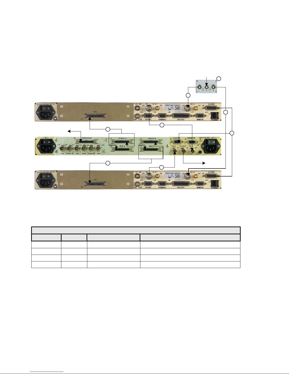
Figure 4-3 illustrates a 1:1 system using a RCS11 with the universal Interface connected to DMD20 or
DMD50 Modems with 70/140 MHz option and G.703/HSSI Interfaces. Table 4-3 describes the connectio n
hardware required.
RX IN
2
1
2
2
2
TX OUT
DATA IN / OUT
3
3
Figure 4-3. RCS11 with HSSI G.703 Interface Connected to DMD20, DMD50 or DMD2050
Modems with G.703 HSSI Interfaces
Table 4-3. Connection Hardware for 70/140 MHz Option
Item No. Quantity Part Number Discription
1 1 RF/ZSC-2-175 70/140 IF Splitter
2 4 CA/3598-36 3’ BNC to BNC 75 Ohm Coaxial Cable
3 2 CA/4181 HSSI Data Cable
4 1 CA/5162 Alarm Fault Cable
4
MN-RCS11 – Rev. 9
Page 5
Errata ER-RCS11-EA9
Comtech EF Data Documentation Update
DMD20,DMD50orDMD2050ASI/DVBwithRCS11ASIHSSI
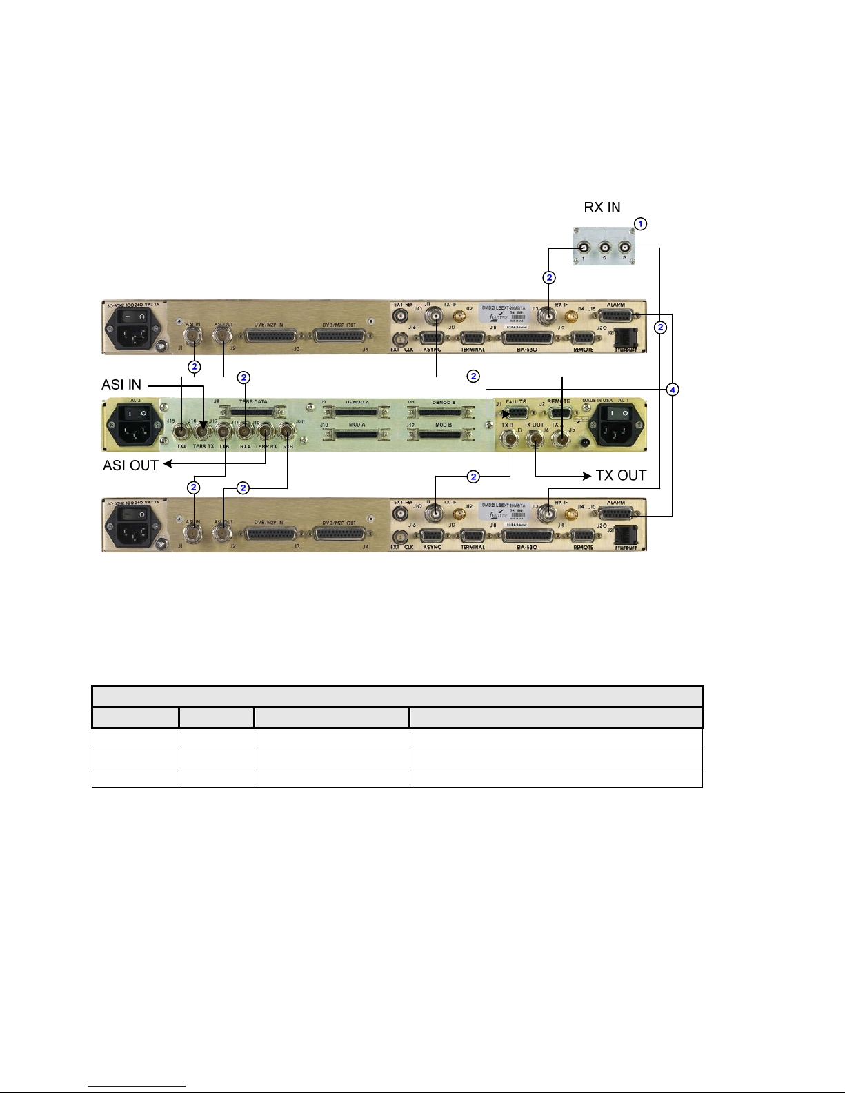
Figure 4-4 illustrates a 1:1 system using a RCS11 with the HSSI / ASI Interface connected to DMD20 or
DMD50 Modems with 70/140 MHz option utilizing the ASI DVB data Interfaces.
Table 4-4 describes the connection hardware required.
Figure 4-4. RCS11 with HSSI ASI Interface Connected to DMD20, DMD50 or DMD2050
Modems with ASI/DVB Interfaces
Table 4-4. Connection Hardware
Item No. Quantity Part Number Discription
1 1 RF/ZSC-2-175 70/140 IF Splitter
2 8 CA/3598-36 3’ BNC to BNC 75 Ohm Coaxial Cable
3 1 CA/5162 Alarm Fault Cable
MN-RCS11 – Rev. 9
Page 6
Errata ER-RCS11-EA9
Comtech EF Data Documentation Update
DMD20HSSI
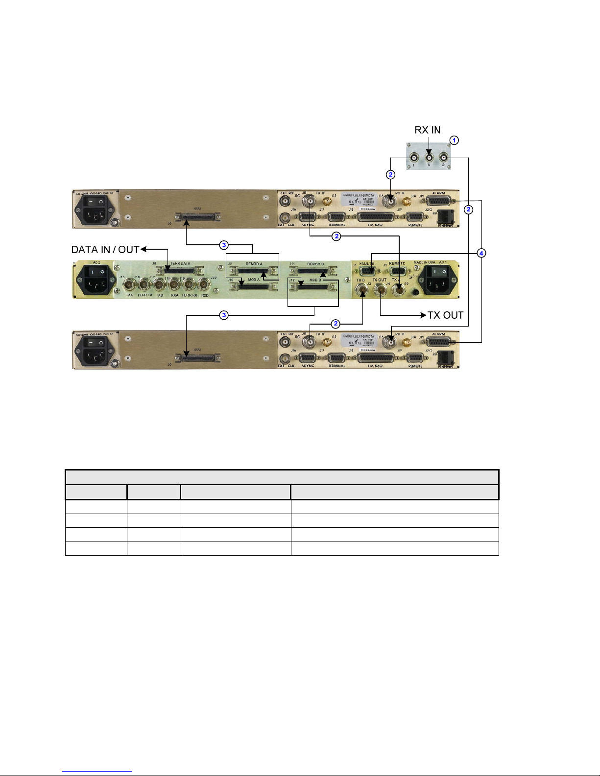
Figure 4-5 illustrates a 1:1 system using a RCS11 with the HSSI / ASI Interface connected to DMD20
Modems with HSSI Interfaces. Table 4-5 describes the connection hardware required.
Figure 4-5. RCS11 with HSSI/ASI Interface Connected to DMD20
Modems with HSSI Interfaces
Table 4-5. Connection Hardware
Item No. Quantity Part Number Discription
1 1 RF/ZSC-2-175 70/140 IF Splitter
2 4 CA/3598-36 3’ BNC to BNC 75 Ohm Coaxial Cable
3 2 CA/4181 HSSI Data Cable
4 1 CA/5162 Alarm Fault Cable
MN-RCS11 – Rev. 9
Page 7

RCS11
1:1 Redundancy Switch
Installation and Operation Manual
Part Number MN-RCS11
Revision 9
September 29, 2009
Copyright © 2009 Comtech EF Data. All rights reserved. Printed in the USA.
Comtech EF Data, 2114 West 7th Street, Tempe, Arizona 85281 USA, 480.333.2200, FAX: 480.333.2161
Page 8

This page is intentionally blank.
Page 9

Table of Contents
TABLE OF CONTENTS .............................................................................................................. III
CHAPTER 1. INTRODUCTION ................................................................................... 1–1
1.1 Description ................................................................................................................................... 1–1
1.2 Redundant Power Supplies ........................................................................................................ 1–1
1.3 Front Panel Controls .................................................................................................................. 1–1
1.4 Power-Up Defaults ...................................................................................................................... 1–2
CHAPTER 2. THEORY OF OPERATION ................................................................... 2–1
2.1 Theory of Operation ................................................................................................................... 2–1
2.2 RCS11 Operation ........................................................................................................................ 2–1
2.2.1 Operating Procedures ............................................................................................................ 2–1
2.2.2 Configuring the RCS11 (Refer to Figure 2-1) ...................................................................... 2–2
2.2.3 Manual Mode ........................................................................................................................ 2–2
2.2.4 Auto Mode ............................................................................................................................ 2–2
2.2.5 Power-Up Defaults ................................................................................................................ 2–2
2.3 RCS11 Major Assemblies ........................................................................................................... 2–2
2.3.1 Main Switch Board ............................................................................................................... 2–3
2.3.2 Front Panel Board ................................................................................................................. 2–3
2.3.3 Redundant Power Supplies ................................................................................................... 2–3
2.4 RCS11 General Operation ......................................................................................................... 2–3
2.4.1 Signals ................................................................................................................................... 2–3
2.4.2 Backup .................................................................................................................................. 2–3
2.4.3
Fail-Safe ................................................................................................................................ 2–4
2.4.4 Fault Relays .......................................................................................................................... 2–4
CHAPTER 3. USER INTERFACES ............................................................................. 3–1
3.1 User Interfaces ............................................................................................................................ 3–1
3.2 Front Panel Interface .................................................................................................................. 3–1
3.3 Rear Panel Interface ................................................................................................................... 3–2
3.3.1 System Installation and Connections .................................................................................... 3–2
3.3.1.1 RCS11 with Universal G.703 Interface ............................................................................ 3–2
iii
Page 10

RCS11 1:1 Redundancy SwitchTable of Contents Revision 9
Table of Contents MN-RCS11
3.3.1.2 ASI Interface with Optional Offline IF Monitor ............................................................... 3–3
3.3.1.3 RCS11 Parallel Interface ................................................................................................... 3–5
3.3.1.4 G.703 – HSSI Interface with G.703 or ASI E3/T3/DS3/STS1 ......................................... 3–6
3.3.1.5 Ethernet Interface .............................................................................................................. 3–7
3.3.1.6 T3/E3/STS1 Interface ....................................................................................................... 3–8
3.3.1.7 Serial Interface .................................................................................................................. 3–9
CHAPTER 4. INSTALLATION .................................................................................... 4–1
4.1 Installation Requirements .......................................................................................................... 4–1
4.2 Unpacking .................................................................................................................................... 4–2
4.2.1 Test Data Sheet ..................................................................................................................... 4–2
4.3 Site Considerations ..................................................................................................................... 4–2
4.3.1 Power Sources ....................................................................................................................... 4–2
4.4 Rack Mounting ............................................................................................................................ 4–3
4.5 System Connections .................................................................................................................... 4–3
4.6 Connections ................................................................................................................................. 4–4
4.6.1 DMD15 Universal ................................................................................................................. 4–4
4.6.2 DMD20 or DMD50 Universal with G.703 IBS/IDR Interface ............................................. 4–5
4.6.3 DMD20 or DMD50 with HSSI Interface .............................................................................. 4–6
4.6.4 DMD20 or DMD50 ASI / DVB with RCS11 ASI HSSI ...................................................... 4–7
4.6.5 DMD20 HSSI ........................................................................................................................ 4–8
4.6.6 DMD20/DMD50 ETHERNET ............................................................................................. 4–9
4.6.7
DMD50 T3 E3 STS1........................................................................................................... 4–10
4.6.8 DM240 PIIC ASI Interface ................................................................................................. 4–11
4.6.9 DM240XR ASI Data Interface ........................................................................................... 4–12
4.6.10 DD240XR Ethernet ............................................................................................................. 4–13
4.6.11 DM240XR Ethernet ............................................................................................................ 4–14
4.6.12 DM240XR HSSI ................................................................................................................. 4–15
4.6.13 DM240XR DVB Parallel .................................................................................................... 4–16
4.6.14 DD240XR HSSI .................................................................................................................. 4–17
4.6.15 DM240XR & DD240XR .................................................................................................... 4–18
4.6.16 DMD20 (RS530) to RCS11 RS449/422 Serial Data Interface ........................................... 4–19
4.6.17 DMD20LBST (RS530) to RCS11 RS449/422 Serial Data Interface ................................. 4–20
CHAPTER 5. CONNECTOR PINOUTS ....................................................................... 5–1
5.1 RCS11 Connections .................................................................................................................... 5–1
5.2 AC Power Input/Switch .............................................................................................................. 5–1
5.3 DC Power Input/Switch .............................................................................................................. 5–1
5.4 RCS11 COMMON CONNECTIONS ....................................................................................... 5–2
iv
Page 11

RCS11 1:1 Redundancy SwitchTable of Contents Revision 9
Table of Contents MN-RCS11
5.4.1 FAULTS (J1) ........................................................................................................................ 5–2
5.4.2 REMOTE (J2) ....................................................................................................................... 5–2
5.4.3 TX B (J3) .............................................................................................................................. 5–3
5.4.4 TX OUT (J4) ......................................................................................................................... 5–3
5.4.5 TX A (J5) .............................................................................................................................. 5–3
5.4.6 GND ...................................................................................................................................... 5–3
5.5 UNIVERSAL G.703/SYNCHROUNOUS INTERFACE ........................................................ 5–3
5.5.1 SYNC DATA (J7) ................................................................................................................. 5–3
5.5.2 MODEM A & B (J7 & J11) G703/RS422 Serial Universal Interface w/SCSI connectors . 5–4
5.5.3 ESC 8K DATA (J15) ............................................................................................................ 5–6
5.5.4 ESC VOICE (J16) ................................................................................................................. 5–7
5.5.5 ESC Alarms (J17) ................................................................................................................. 5–7
5.5.6 ES/ES (J18) Universal Interface ........................................................................................... 5–8
5.5.7 G.703 Balanced (J20) ............................................................................................................ 5–8
5.5.8 SD (DDI) (J23) ..................................................................................................................... 5–9
5.5.9 DDO (J24) ............................................................................................................................. 5–9
5.5.10 IDI (J25) ................................................................................................................................ 5–9
5.5.11 RD (IDO) (J26) ..................................................................................................................... 5–9
5.6 ASI Data Interface ...................................................................................................................... 5–9
5.6.1 DATA A (J7) ........................................................................................................................ 5–9
5.6.2 ASI TERR (J10) .................................................................................................................... 5–9
5.6.3 DATA B (J11) ....................................................................................................................... 5–9
5.6.4 Alarm A (J18) ....................................................................................................................... 5–9
5.6.5 Alarm B (J19) ..................................................................................................................... 5–10
5.7 DVB Parallel Interfaces ............................................................................................................ 5–10
5.7.1 Data A & Data B DVB Parallel Interface (J7) .................................................................... 5–10
5.7.1.1 Data A & Data B M2P Parallel Interface (J7 & J11) ...................................................... 5–11
5.7.2 Terrestrial Data (J10) DVB Parallel Interface .................................................................... 5–12
5.7.2.1 Terrestrial Data (J10) M2P Data Interface ...................................................................... 5–13
5.7.3 Alarm A (J18) ..................................................................................................................... 5–14
5.7.4 Alarm B (J19) ..................................................................................................................... 5–14
5.8 DMD50 UNIVERSAL G703 T3/E3 & RS422 SERIAL INTERFACE w/SCSI .................. 5–14
5.8.1 EIA 530 (J36) ...................................................................................................................... 5–14
5.8.2 MODEM A & B (J7 & J11) Universal Interface, G703/Synchrounous Data w/SCSI
connectors ........................................................................................................................................... 5–15
5.8.3 ESC 8K DATA (J15) .......................................................................................................... 5–17
5.8.4 ESC VOICE (J16) ............................................................................................................... 5–17
5.8.5 ESC Alarms (J17) ............................................................................................................... 5–18
5.8.6 ES/ES (J18) Universal Interface ......................................................................................... 5–19
5.8.7 RXB (J30) ........................................................................................................................... 5–19
5.8.8 TERR RX (J31) ................................................................................................................... 5–19
5.8.9 RXA (J32) ........................................................................................................................... 5–19
5.8.10
TXB (J33) ........................................................................................................................... 5–19
5.8.11 TERR TX (J34) ................................................................................................................... 5–19
5.8.12 TXA (J35) ........................................................................................................................... 5–19
v
Page 12

RCS11 1:1 Redundancy SwitchTable of Contents Revision 9
Table of Contents MN-RCS11
5.9 High-Speed Serial Interface (HSSI) & ASI or G703 Interface (Optional) .......................... 5–20
5.9.1 HSSI TERR DATA (J8) ..................................................................................................... 5–20
5.9.2 ASI or G703 Data Interface ................................................................................................ 5–20
5.9.2.1 TXA ASI or G703 (J15) ................................................................................................. 5–20
5.9.2.2 TERR TX ASI or G703 (J16) ......................................................................................... 5–20
5.9.2.3 TXB - ASI or G703 (J17) ............................................................................................... 5–21
5.9.2.4 RXA - ASI or G703 (J18) ............................................................................................... 5–21
5.9.2.5 TERR RX - ASI or G703 (J19) ....................................................................................... 5–21
5.9.2.6 RXB - ASI or G.703 (J20) .............................................................................................. 5–21
5.9.3 FAULTS (J1) ...................................................................................................................... 5–21
5.10 ETHERNET & RS530 DATA INTERFACE ......................................................................... 5–22
5.10.1 EIA 530 (J10) ...................................................................................................................... 5–22
5.10.2 Ethernet Interface ................................................................................................................ 5–23
5.10.2.1 DATA B (J27) ................................................................................................................. 5–23
5.10.2.2 TERR DATA (J28) ......................................................................................................... 5–23
5.10.2.3 DATA A (J29) ................................................................................................................ 5–23
5.10.2.4 SWITCH (S1) ................................................................................................................. 5–23
5.11 SERIAL INTERFACE ............................................................................................................. 5–23
5.11.1 TERRESTRIAL RS449/RS422 SERIAL DATA (J10) ...................................................... 5–24
5.11.2 DATA A & B (J7 & J11) .................................................................................................... 5–25
CHAPTER 6. MAINTENANCE AND TROUBLESHOOTING ...................................... 6–1
6.1 Basic Troubleshooting and Maintenance .................................................................................. 6–1
6.2 Basic User Checks ....................................................................................................................... 6–1
6.2.1 Checking the Fuses ............................................................................................................... 6–1
6.2.2 Checking the Cabling and Connectors .................................................................................. 6–2
6.3 Major and Minor Faults ............................................................................................................. 6–2
CHAPTER 7. TECHNICAL SPECIFICATIONS ........................................................... 7–1
7.1 Introduction ................................................................................................................................. 7–1
7.2 General ......................................................................................................................................... 7–1
7.3 Monitor and Control ................................................................................................................... 7–1
7.4 Terrestrial Interfaces .................................................................................................................. 7–1
7.5 Front Panel LED Indicators ....................................................................................................... 7–2
7.6 Front Panel Controls .................................................................................................................. 7–2
7.7 Power and Environmental .......................................................................................................... 7–2
vi
Page 13

RCS11 1:1 Redundancy SwitchTable of Contents Revision 9
Table of Contents MN-RCS11
7.8 Storage Temperature: -2 0 to 70°C, 99% Humidity, Noncondensing Physical ...................... 7–2
APPENDIX A. RCS11 DIP SWITCH CONFIGURATION ............................................. A–1
APPENDIX B. RCS11 REMOTE COMMUNICATIONS ............................................... B–1
B.1 Host Computer Remote Communications ............................................................................... B–1
B.1.1 Protocol Structure ................................................................................................................ B–1
B.1.2 Protocol Wrapper ................................................................................................................. B–2
B.1.3 Frame Description and Bus Handshaking ............................................................................ B–3
B.1.4 Global Response Operational Codes .................................................................................... B–4
B.1.5 Software Compatibility ........................................................................................................ B–5
B.1.6 RLLP Summary ................................................................................................................... B–5
B.2 Remote Port Packet Structure: ................................................................................................. B–6
APPENDIX C. TERMINAL COMMUNICATIONS ........................................................ C–1
vii
Page 14

RCS11 1:1 Redundancy SwitchTable of Contents Revision 9
Table of Contents MN-RCS11
Notes:
viii
Page 15

PREFACE
About this Manual
This manual describes the installation and operation for the Radyne RCS11. This is a technical
document intended for earth station engineers, technicians, and operators responsible for the
operation and maintenance of the RCS11.
Reporting Comments or Suggestions Concerning this Manual
Comments and suggestions regarding the content and design of this manual are appreciated. To
submit comments, please contact the Comtech EF Data Technical Publications department:
TechnicalPublications@comtechefdata.com
Conventions and References
Related Documents
The following documents are referenced in this manual:
MN-DMD20-20LBST
MN-DMD2050
MN-DMD50
MN-DM240XR
MN-DD240XR
MN-DD2401
Metric Conversion
Metric conversion information is located on the inside back cover of this manual. This information is
provided to assist the operator in cross-referencing non-Metric to Metric conversions.
i
Page 16

RCS11 1:1 Redundancy Switch Revision 9
Preface MN-RCS11
Cautions and Warnings
IMPORTANT or NOTE indicates a statement associated wi th the task
IMPORTANT
CAUTION
WARNING
being performed or information critical for proper equipment function.
CAUTION indicates a hazardous situation that, if not avoided, may result in
minor or moderate injury. CAUTION may also be used to indicate other
unsafe practices or risks of property damage.
WARNING indicates a potentially hazardous situation that, if not avoided,
could result in death or serious injury.
Examples of
Multi-Hazard Formats
Trademarks
Product names mentioned in this manual may be trademarks or registered trademarks of their
respective companies and are hereby acknowledged.
ii
Page 17
RCS11 1:1 Redundancy Switch Revision 9
Preface MN-RCS11
Safety Compliance
EN 60950
Applicable testing is routinely performed as a condition of manufacturing on all units to ensure
compliance with safety requirements of EN60950.This equipment meets the Safety of Information
Technology Equipment specification as defined in EN60950.
Low Voltage Directive (LVD)
The following information is applicable for the European Low Voltage Directive (EN60950):
<HAR> Type of power cord required for use in the European Community.
!
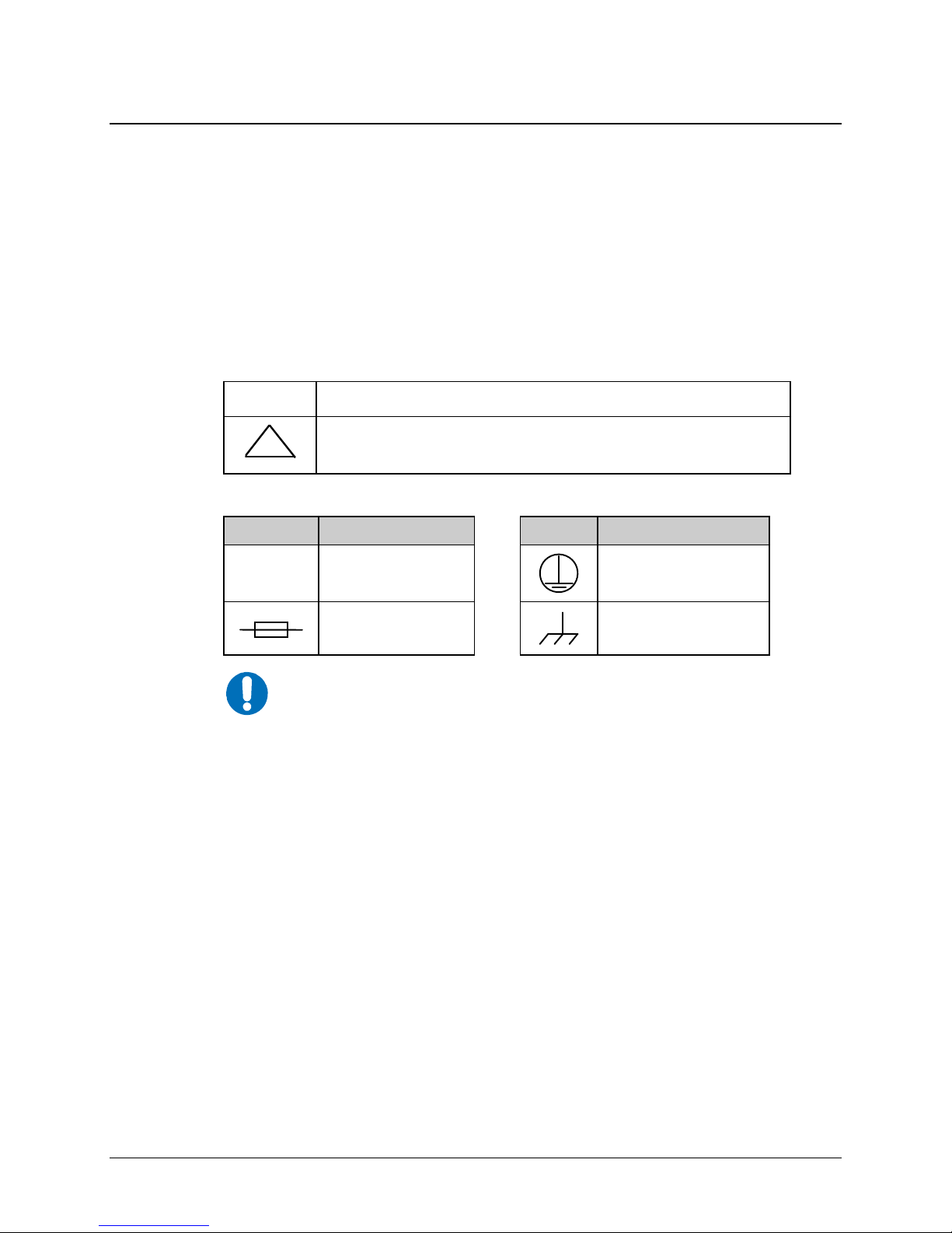
International Symbols:
Symbol Definition Symbol Definition
~
NOTE
CAUTION: Double-pole/Neutral Fusing
ACHTUNG: Zweipolige bzw. Neutralleiter-Siche rung
Alternating Current
For additional symbols, refer to Cautions and Warnings, listed
earlier in this Preface.
Fuse
Protective Earth /
Safety Ground
Chassis Ground
iii
Page 18

RCS11 1:1 Redundancy Switch Revision 9
Preface MN-RCS11
Warranty Policy
Comtech EF Data products are warranted against defects in material and
workmanship for a period of two years from the date of shipment. During the
warranty period, Comtech EF Data will, at its option, repair or replace products
that prove to be defective. Repairs are warranted for the remainder of the original
two year warranty, or a 90 day extended warranty, whichever is longer.
For equipment under warranty, the owner is responsible for freight to Comtech E F
Data and all related customs, taxes, tariffs, insurance, etc. Comtech EF Data is
responsible for the freight charges only for return of the equipment from the factory
to the owner. Comtech EF Data will return the equipment by the same method
(i.e., Air, Express, Surface) as the equipment was sent to Comtech EF Data.
All equipment returned for warranty repair must have a valid RMA number issued
prior to return and be marked clearly on the return packaging. Comtech EF Data
strongly recommends all equipment be returned in its original packaging.
Comtech EF Data Corporation’s obligations under this warranty are limited to
repair or replacement of failed parts, and the return shipment to the buyer of the
repaired or replaced parts.
Limitations of Warranty
The warranty does not apply to any part of a product that has been installed,
altered, repaired, or misused in any way that, in the opinion of Comtech EF Data
Corporation, would affect the reliability or detracts from the performance of any
part of the product, or is damaged as the result of use in a way or with equipment
that had not been previously approved by Comtech EF Data Corporation.
The warranty does not apply to any product or parts thereof where the serial number
or the serial number of any of its parts has been altered, defaced, or removed.
The warranty does not cover damage or loss incurred in transportation of the
product.
The warranty does not cover replacement or repair necessitated by loss or
damage from any cause beyond the control of Comtech EF Data Corporation,
such as lightning or other natural and weather related events or wartime
environments.
The warranty does not cover any labor involved in the removal and or
reinstallation of warranted equipment or parts on site, or any labor required to
diagnose the necessity for repair or replacement.
iv
Page 19

RCS11 1:1 Redundancy Switch Revision 9
Preface MN-RCS11
The warranty excludes any responsibility by Comtech EF Data Corporation for
incidental or consequential damages arising from the use of the equipment or
products, or for any inability to use them either separate from or in combination with
any other equipment or products.
A fixed charge established for each product will be imposed for all equipment
returned for warranty repair where Comtech EF Data Corporation cannot identify
the cause of the reported failure.
Exclusive Remedies
Comtech EF Data Corporation’s warranty, as stated is in lieu of all other
warranties, expressed, implied, or statutory, including those of merchantability
and fitness for a particular purpose. The buyer shall pass on to any purchaser,
lessee, or other user of Comtech EF Data Corporation’s products, the
aforementioned warranty, and shall indemnify and hold harmless Comtech EF
Data Corporation from any claims or liability of such purchaser, lessee, or user
based upon allegations that the buyer, its agents, or employees have made
additional warranties or representations as to product preference or use.
The remedies provided herein are the buyer’s sole and exclusive remedies.
Comtech EF Data shall not be liable for any direct, indirect, special, incidental, or
consequential damages, whether based on contract, tort, or any other legal
theory.
v
Page 20

RCS11 1:1 Redundancy Switch Revision 9
Preface MN-RCS11
Customer Support
Contact the Comtech EF Data Customer Support Department for:
Product support or training
Reporting comments or suggestions concerning manuals
Information on upgrading or returning a product
A Customer Support representative may be reached at:
Comtech EF Data
Attention: Customer Support Department
2114 West 7th Street
Tempe, Arizona 85281 USA
480.333.2200 (Main Comtech EF Data number)
480.333.4357 (Customer Support Desk)
480.333.2161 FAX
To return a Comtech EF Data product (in-warranty and out-of-warranty) for repair or replacement:
Contact the Comtech EF Data Customer Support Department. Be prepared to supply
the Customer Support representative with the model number, serial number, and a
description of the problem.
Request a Return Material Authorization (RMA) number from the Comtech EF Data
Customer Support representative.
Pack the product in its original shipping carton/packaging to ensure that the product is
not damaged during shipping.
Ship the product back to Comtech EF Data. (Shipping charges should be prepaid.)
Online Customer Support
An RMA number request can be requested electronically by contacting the Customer Support
Department through the online support page at www.comtechefdata.com/support.asp:
Click on the “Service” hyperlink, then read the “Return Material Authorization” section
for detailed instructions on our return procedures.
Click on the “RMA Request Form” hyperlink, then fill out the form completely before
sending.
Send e-mail to the Customer Support Department at service @comt echefdat a.com .
For information regarding this product’s warranty policy, refer to the Warranty Policy, p. xxii.
vi
Page 21
Chapter 1. INTRODUCTION
1.1 Description
The Radyne RCS11 1:1 Redundancy Switch provides simple backup redundancy protection for
most configurations of the DMD15, DMD20, DMD50 and DMD2050 Satellite Modems as well as
the DM240XR Video Modulator and DD240XR Video Demodulator. The backup functions of the
RCS11 may be performed manually via the front panel or from the Terminal Mode. Refer to
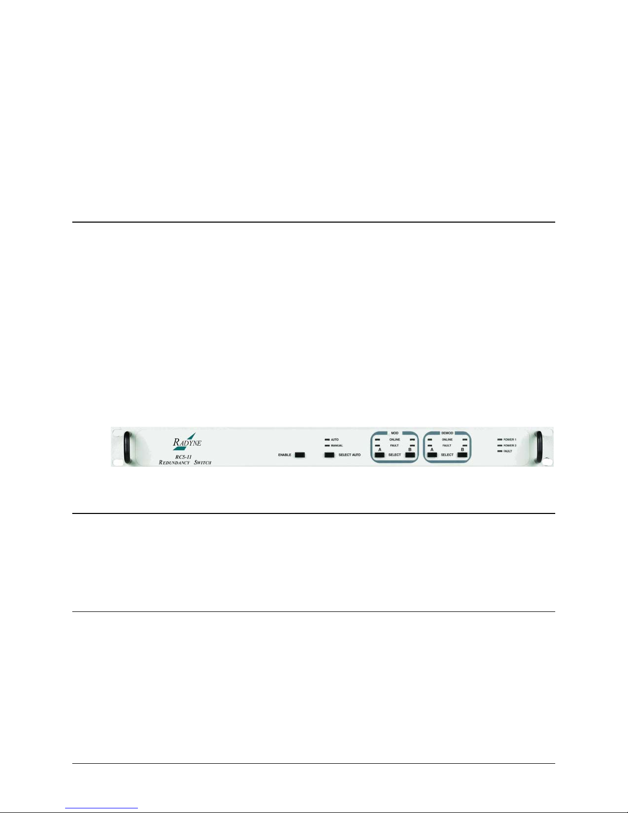
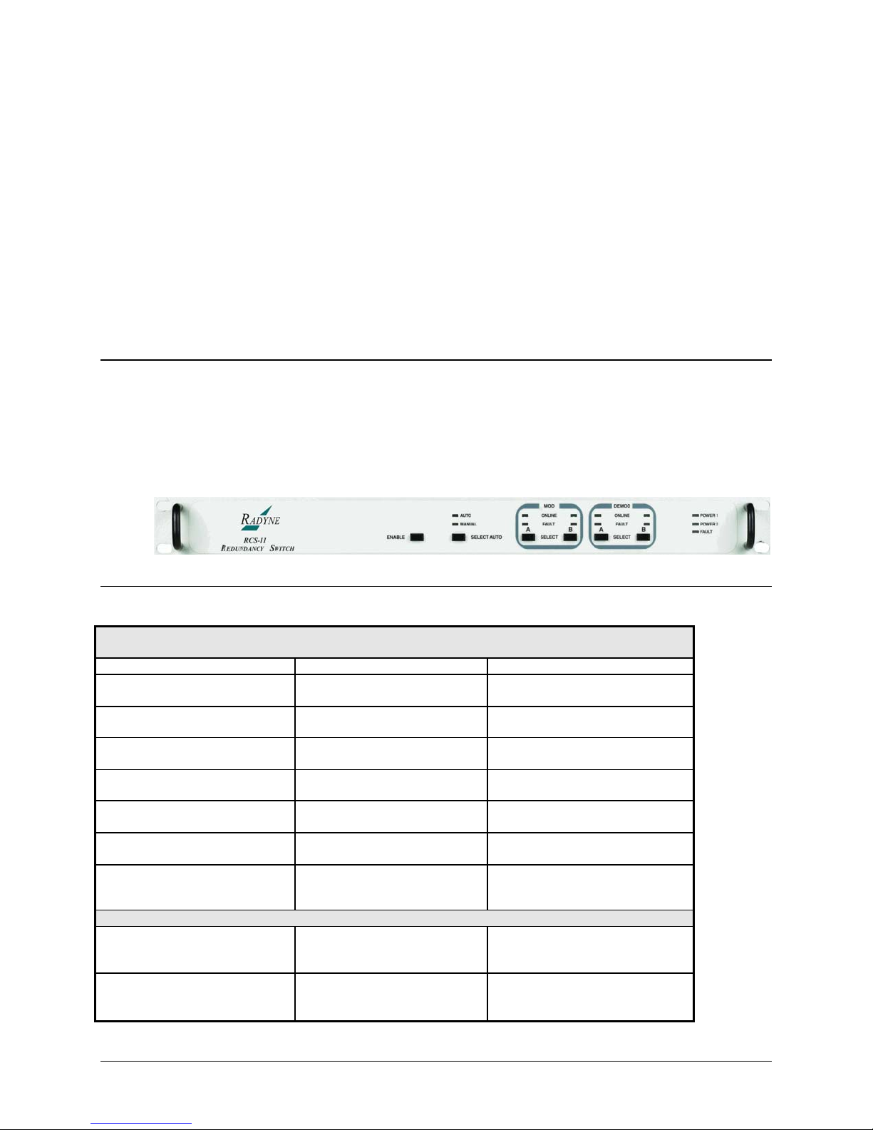
Figure 1-1 for an illustration of the RCS11 1:1 Redundancy Switch Front Panel, Figure 1-2 for the
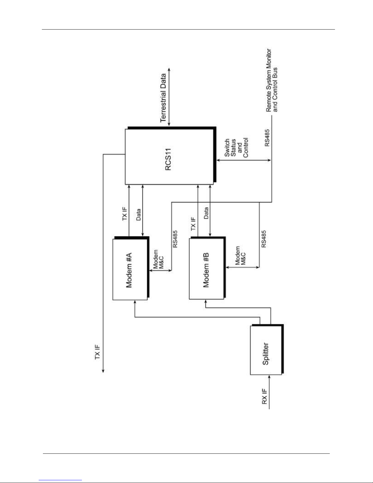
Interface options of the RCS11 and Figure 1-3 of a RCS11 Fucntional Block Diagram.
The RCS11 redundant 1:1 switch supports various product configurations that require different
setups. The switch can support a modem, modulator or demodulator only applications.
Operating in the Automatic Mode, the RCS11 immediately places a Backup Modem online in the
event of a Primary Online Modem failure. In the Manual Mode, the user may designate the
selected Online Primary Modem from either the Interactive Front Panel or a remote Terminal
Interface.
Figure 1-1. RCS11 1:1 Redundancy Switch Front Panel
1.2 Redundant Power Supplies
The RCS11 is equipped with two fully redundant internal power. Each power supply is fully
independent of the other, including their source of AC power and fusing. The RCS11 remains
fully operational as long as either power supply is providing a source of power. The power
supplies are located one on either side of the front of the RCS11 Chassis.
1.3 Front Panel Controls
The Front Panel of the RCS11 provides all of the necessary controls and LED indicators to
provide the operator with online status and backup status of the online and backup Modulators
and deModulators.
MN-RCS11 – Revision 9 1–1
Page 22
RCS11 1:1 Redundancy Switch Introduction
1.4 Power-Up Defaults
During power-up, the RCS11 initializes itself to the last mode set by the Front Panel Pushbuttons.
For example, if the operator desires the RCS11 to operate in the Auto Mode, with both the
Modulator and Demodulator set to Modem B, the operator places the RCS11 into this condition
using the Front Panel Pushbuttons and the RCS11 stores this configuration into nonvolatile
memory. If the power source was then to fail and be restored, the RCS11 would again power-up
in the Auto Mode with both the Modulator and Demodulator set to Modem B.
Universal with G.703 IBS/IDR Interface w/ 70/140 IF TX (used with DMD15/20/50)
Universal with G.703 IBS/IDR Interface w/L-Band IF (used with DMD15/20/50)
ASI Interface w/ 70/140 IF TX or RX only option (used with DM240XR or DD240XR)
ASI Interface w/ L-Band IF TX or RX only options (used with DM240XR or DD240XR)
Optional ASI Interface with Offline 70/140 IF Monitor (used with DM240XR)
Optional Parallel Interface (used with DM240XR or DD240XR)
MN-RCS11 – Revision 9 1–2
Page 23
RCS11 1:1 Redundancy Switch Introduction
Optional HSSI and G703 or ASI Interface used with DM240XR,
DD240XR, DMD20, DMD50
Optional Ethernet Interface (used with DM240XR, DD240XR, DMD20/50)
Optional T3/E3 Interface (used with DMD50 only)
Optional RS449/RS422 Serial interface
MN-RCS11 – Revision 9 1–3
Page 24
RCS11 1:1 Redundancy Switch Introduction
MN-RCS11 – Revision 9 1–4
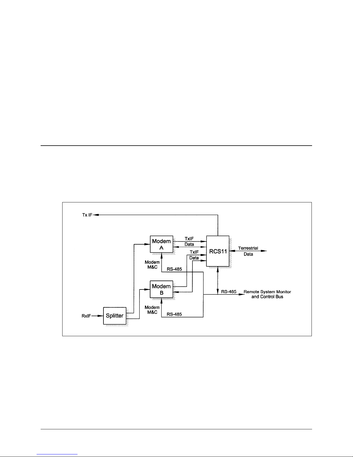
Figure 1-3. RCS11 Functional Block Diagram
Page 25
Chapter 2. Theory of Operation
2.1 Theory of Operation
2.2 RCS11 Operation
A block diagram of the signal flow is shown in Figure 2-1 below.
2.2.1 Operating Procedures
The RCS11 is designed to require minimal operator intervention and control during normal
operation. After initial setup, the unit should operate in a relatively ‘transparent’ manner,
providing trouble-free backup of the online Modems. The scope of this section is limited to
instruction on the various modes of control available to the operator. Refer to Section 3-1 for the
RCS11 Front Panel Controls and Indicators and Table 3-1 for a description of the Controls and
Indicators.
MN-RCS11 – Revision 9 2–1
Figure 2-1. Functional Block Diagram
Page 26

RCS11 1:1 Redundancy Switch Theory of Operation
2.2.2 Configuring the RCS11 (Refer to Figure 2-1)
The purpose of the ‘ENABLE’ pushbutton on the front panel is to reduce the risk of accidentally
changing the operating modes of the RCS11 by accidentally bumping any one of the front panel
pushbuttons. For any one of the front panel pushbuttons to function, the ‘ENABLE’ pushbutton
must be depressed simultaneously with the desired function pushbutton.
Depress the ‘ENABLE’ pushbutton. This pushbutton must be depressed to allow the operator to
proceed with any other configurations. The ‘MANUAL’ LED should illuminate and the FAULT
indicator may momentarily flash. Under the MOD region of the front panel, depress ‘SELECT A’
to bring Modem ‘A’ modulator online. The green LED should illuminate. Under the DEMOD
region of the front panel, depress ‘SELECT A’ to bring modem ‘A’ demodulator online. The
Green LED should illuminate. The RCS11 should now be in backup mode with modem ‘A’ on line.
2.2.3 Manual Mode
To manually select which MOD or DEMOD is to be placed online, simultaneousl y depress the
‘ENABLE’ pushbutton and the appropriate MOD or DEMOD ‘SELECT’ pushbutton. When a MOD
or DEMOD selection is made, the RCS11 enters Manual Mode to carry out the selection, and will
not respond to either modem’s MOD or DEMOD Fault signals until placed back into Auto Mode.
2.2.4 Auto Mode
To enable automatic backup in the event of a MOD or DEMOD failure, the RCS11 must be
placed into the Auto Mode. First, select which MOD and DEMOD are to be active by following
the ‘Manual Mode’ procedure in the previous paragraph. To enter the Auto Mode, simultaneously
depress the ‘ENABLE’ pushbutton and the ‘SELECT AUTO’ pushbutton. The RCS11 will then
enter into Auto Mode with the last selections made in Manual Mode. In the Auto Mode, the
decision to switch from one MOD or DEMOD to another is made automatically by monitoring the
Fault signals from each modem.
2.2.5 Power-Up Defaults
During power-Up, the RCS11 initializes itself to the last mode set by the operator on the front
panel pushbuttons. For example, if the operator desires the RCS11 to operate in the Auto Mode,
with both Mod and Demod set to Modem B, by placing the RCS11 into this condition using the
front panel pushbuttons, the settings are stored into non-volatile memory. If MOD B was to fail,
and the RCS11 was to backup with MOD A, the new backup setting would not be saved. If the
power was to be removed and restored, the RCS11 would again power-up in AUTO MODE, with
both MOD and DEMOD set to Modem B.
2.3 RCS11 Major Assemblies
The RCS11 Redundancy Control Unit contains the modules that control and monitor the
operation of the 1:1 Switch system. The 1:1 Switch is composed of the following major
assemblies and components:
Main Switch Board
Front Panel Board
Dual Redundant Power Supplies
MN-RCS11 – Revision 9 2–2
Page 27

RCS11 1:1 Redundancy Switch Theory of Operation
2.3.1 Main Switch Board
The Main Switch Board contains the RCS11 1:1 Switch Intelligence and Memory Circuitry and all
switching circuitry. The on-board microprocessor is an MC68HC11, which has a 16-bit address
bus and an 8-bit data bus. The microprocessor controls and coordinates all of the major
functions of the Switch and performs all necessary calculations. The non-volatile system memory
on the board stores the switching parameter settings for ea ch modem channel. Control and data
signals are routed to the appropriate devices in the system through various latches and
transceivers that are controlled by the microprocessor.
2.3.2 Front Panel Board
The Front Panel Board contains the LED Indicators and the pushbutton switches needed to
control and operate the RCS11. Refer to Figure 3.0 for a description of Front Panel Indicators.
2.3.3 Redundant Power Supplies
The 1:1 Switch comes equipped with two fully redundant internal power supplies (PS1 and PS2)
that supplies power to the system. Each supply is fully independent of the other, including their
source of AC power and fusing.
The Switch can remain fully operational as long as it is supplied with a source of voltage from
either power supply. PS1 and PS2 are located one on either side at the rear of RCS11 chassis.
2.4 RCS11 General Operation
2.4.1 Signals
All necessary Modem signals are backed-up through a passive switching system. Signals that
are required to maintain the modem in off-line (hot-standby) are buffered by appropriate circuitry
to minimize loading on incoming signals.
2.4.2 Backup
If an online MOD fault is sensed, and the off-line MOD is in a non-faulted state, the RCS11 will
switch to the MOD without the fault. The Fault Signal has a small debounce delay to prevent
false triggering. If the faulted MOD has its fault cleared, it stays off-line unless the other MOD
has subsequently faulted. The DEMOD faults are handled in a similar manner, but the fault
signals have longer debounce delays to allow for Demodulator acquisition time.
MN-RCS11 – Revision 9 2–3
Page 28

RCS11 1:1 Redundancy Switch Theory of Operation
2.4.3 Fail-Safe
If the RCS11 has a non-recoverable internal fault, the MOD and DEMOD both revert back to
Modem A, the Switch Fault LED is illuminated, and the Switch Fault Relay switches to a faulted
state.
If Power Supply 1 and Power Supply 2 simultaneously fail, the switching circuitry in the RCS11
reverts back to Modem A, and the Switch Fault Relay switches to a faulted state. Modem B does
not receive buffered signals in this condition.
2.4.4 Fault Relays
Fault Connector (J1), has Form-C contacts to indicate the state of the MOD and DEMOD
selections. An additional Form-C contact is available to indicate an RCS11 Fault.
MN-RCS11 – Revision 9 2–4
Page 29
Chapter 3. User Interfaces
3.1 User Interfaces
There are four user Interfaces available for the RCS11. These are:
Front Panel
Remote Port
Terminal
3.2 Front Panel Interface
Table 3-1. RCS11 Front Panel Controls and Indicators
Nomenclature Description Function
Power 1 Indicates PS1 has
Power 2 Indicates PS2 has
Fault Indicates a Switch
Auto (LED) Indicates RCS11 is in
Manual (LED) Indicates the RSC11
ENABLE (Pushbutton) ------------------- Enables Front Panel
SELECT AUTO
(Pushbutton)
Demodulator Controls and Indicators
Online LED Indicates which
Fault LED The RCS11 has
LED illuminates Green
power applied
power applied
Fault has occurred
the Auto Mode
is in the Manual Mode
------------------- Allows the operator to
Demodulator is
online: A or B
received a
Demodulator fault
for Power Available
LED illuminates Green
for Power Available
LED illuminates Red for
Switch Fault
LED illuminates Green
for Auto Mode
LED illuminates Green
for Manual Mode
controls to function
select Automatic Mode
of operation
LED illuminates green
for Online
LED illuminates Red for
Fault
MN-RCS11 – Revision 9 3–1
Page 30

RCS11 1:1 Redundancy Switch User Interfaces
from Modem A or B
SELECT Demod A or
B (Pushbutton)
Online LED Indicates which
Fault LED The RCS11 has
SELECT Mod A or B
(Pushbutton)
-------------------- Allows the operator to
Modulator Controls and Indicators
Modulator is online:
A or B
received a fault from
Modulator A or B
---------------------- Allows the operator to
3.3 Rear Panel Interface
3.3.1 System Installation and Connections
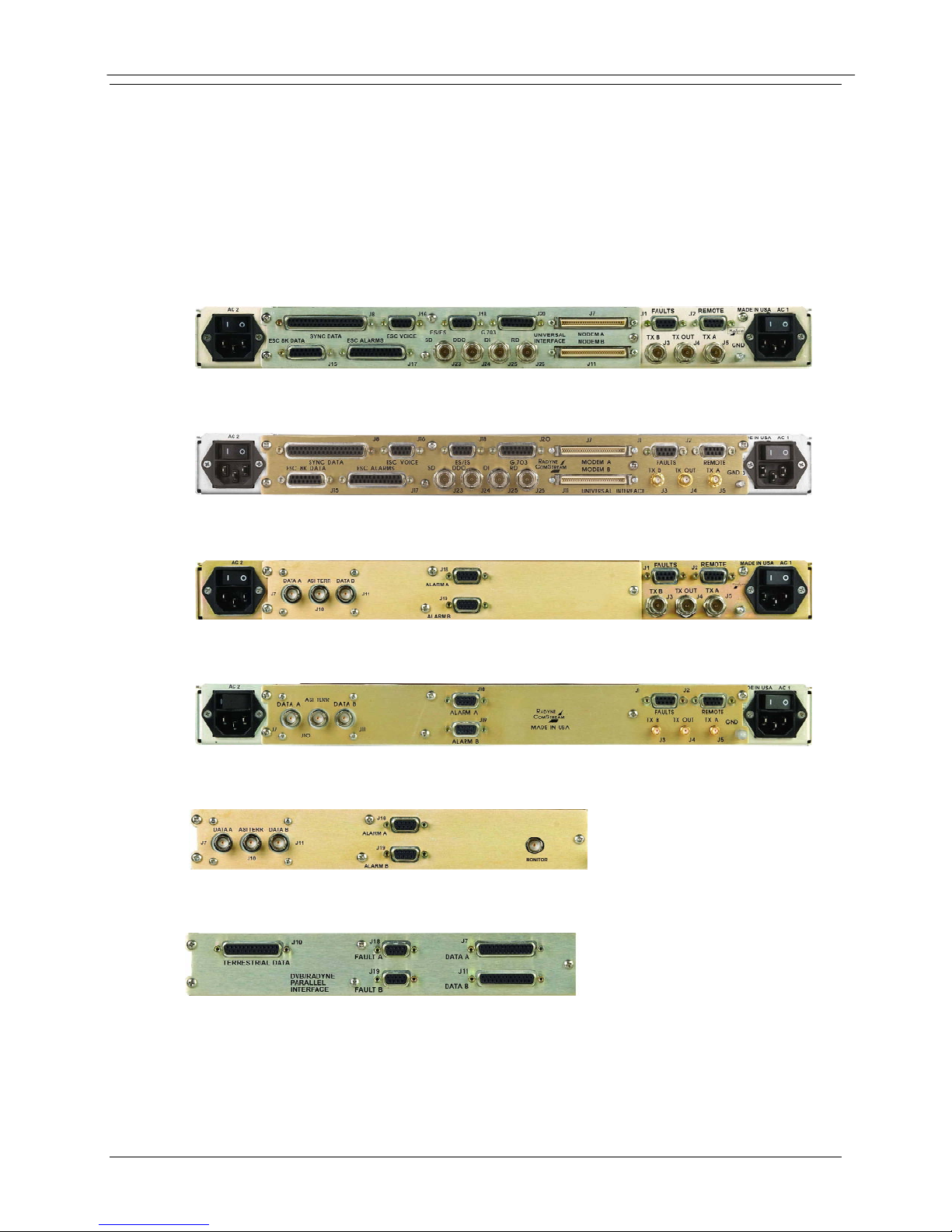
3.3.1.1 RCS11 with Universal G.703 Interface
Figure 3-1 illustrates the RCS11 with the Universal G.703 Interface available with either AC or DC
power entry and 70/140 or L-Band Intermediate Frequency. Table 3-1 describes the connect ion
hardware required.
select a Demodulator: A
or B
LED illuminates green
for Online
LED illuminates Red for
Fault
select a Modulator: A or
B
Figure 3-1. RCS11 with the Universal G.703 Interface
MN-RCS11 – Revision 9 3–2
Page 31

RCS11 1:1 Redundancy Switch User Interfaces
Table 3-1. Connection Hardware
LOCATION CONNECTOR DESCRIPTION
AC1 / AC2 IEC/EN60320/C/3
Power Entry Module for Primary and
Back Up AC
DC1 / DC2
MS3102A10SC3P
Power Entry Module for Primary and
Back Up DC
J1 FAULT 9-Pin F D Sub. Switch Fault Status
J2 REMOTE 9-Pin F D Sub. 232 or 485 Communications
J3 TX B BNC IF Transmit Input From Primary Device
J4 TX Out BNC Main IF Output
J5 TX A BNC IF Transmit Input From Back Up Device
J7 MODEM A SCSI Data and Fault Primary Device
J8 SYNC DATA 37-Pin F D Sub In and Out Synchronous Data
J11 MODEM B SCSI Data and Fault Back Up Device
J15 ECS 8K
15-Pin F D Sub Eng. Service Channel for Teletype
DATA
J16 ESC VOICE 9-Pin F D Sub.
Eng. Service Channel for Voice or 64K
Data
J17 ESC
25-Pin F D Sub
ALARMS
J18 ES/ES 9-Pin F D Sub.
Eng. Service Channel for Backward
Alarm Reporting
Earth Station To Earth Station
Communication
J20 G.703 15-Pin F D Sub Balanced Asynchronous Data
J23 SD BNC Serial Send Data
J24 DDO BNC Drop Data Output
J25 IDI BNC Insert Data Input
J26 RD BNC Serial Receives Data
3.3.1.2 ASI Interface with Optional Offline IF Monitor
Figure 3-2 illustrates the RCS11 ASI Interface with the optional offline IF monitor port. This is
used to monitor either the primary or back up data stream when in the offline state. The offline IF
monitor port is available with the ASI Interface only. Table 3-2 describes the connection hardware
required.
MN-RCS11 – Revision 9 3–3
Page 32

RCS11 1:1 Redundancy Switch User Interfaces
Figure 3-2. RCS11 ASI Interface for DM240XR or DD240XR
Table 3-2. Connection Hardware
LOCATION CONNECTOR DESCRIPTION
J7 DATA A BNC
J10 ASI TERR BNC
J11 DATA B BNC
J18 ALARM A 9-Pin D Sub
J19 ALARM B 9-Pin D Sub
Asynchronous Data
from Primary Device
Asynchronous Data
Out
Asynchronous Data
from Back Up Device
Alarm Fault Primary
Device
Alarm Fault Back Up
Device
J20 MONITOR BNC Offline IF Monitor
MN-RCS11 – Revision 9 3–4
Page 33

RCS11 1:1 Redundancy Switch User Interfaces
3.3.1.3 RCS11 Parallel Interface
Figure 3-3 illustrates the RCS11 DVB Parallel Data Interface (RS422 and LVDS Parallel). Table
3-3 describes the connection hardware required.
Figure 3-3: RCS11 DVB Parallel Interface (RS422 and LVDS)
Table 3-3. Connection Hardware
LOCATION CONNECTOR DESCRIPTION
J7 DATA A 25-Pin F D Sub Parallel RS422 and
LVDS Data A
J10 TERRESTRIAL
DATA
J11 DATA B 25-Pin F D Sub Parallel RS422 and
J18 FAULT A 9-Pin F D Sub Alarm Fault Primary
J19 FAULT B 9-Pin F D Sub Alarm Fault Back Up
25-Pin F D Sub Parall el Data Input
LVDS Data B
Device
Device
MN-RCS11 – Revision 9 3–5
Page 34

RCS11 1:1 Redundancy Switch User Interfaces
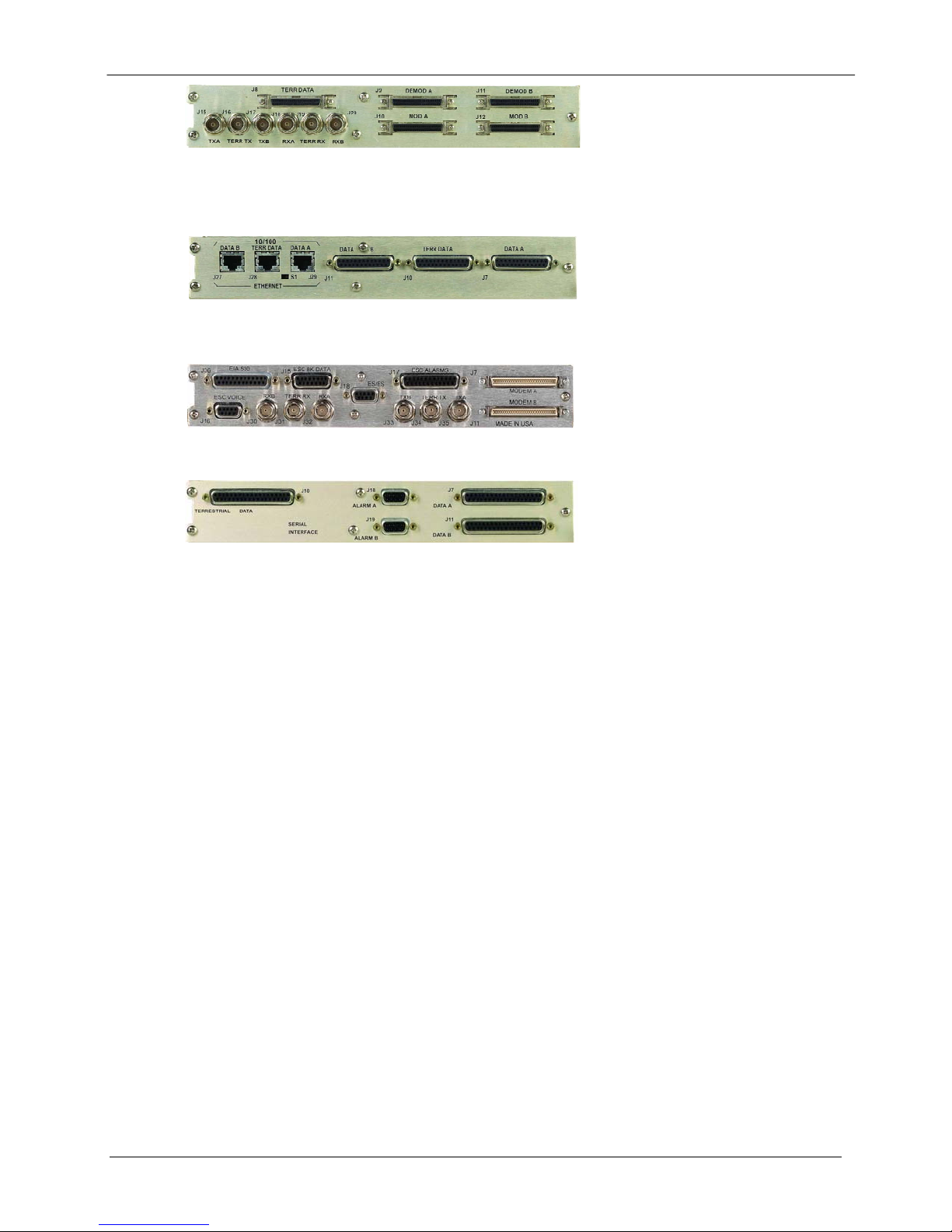
3.3.1.4 G.703 – HSSI Interface with G.703 or ASI E3/T3/DS3/STS1
Figure 3-4 illustrates the RCS11 HSSI Interface and optional G.703 or ASI data interface. The
RCS11 must be configured from the factory to support ASI or G703. The G703 rates supported
are E3, T3 and STS. Table 3-4 describes the connection hardware required. (For G.703 with IDR
ESC support Refer to 3.3.1.6)
IMPORTANT
G.703 Interface can be configured from the factory to support ASI.
(Asynchronous Serial Interface)
Figure 3-4. RCS11 HSSI / G.703 Interface
Table 3-4. Connection Hardware
LOCATION CONNECTOR DESCRIPTION
J8 TERR DATA HSSI Data Input / Output
J9 DEMOD A HSSI Demodulator Primary
J10 MOD A HSSI Modulator Primary
J11 DEMOD B HSSI Demodulator Back Up
J12 MOD B HSSI Modulator Back Up
J15 TX A BNC G.703 T3/E3 Optional ASI
Primary
J16 TERR TX BNC G.703 T3/E3 Optional ASI
Data In
J17 TX B BNC G.703 T3/E3 Optional ASI
Back Up
J18 RX A BNC G.703 T3/E3 Optional ASI
Primary
J19 TERR RX BNC G.703 T3/E3 Optional ASI
Data Out
J20 RX B BNC G.703 T3/E3 Optional ASI
Back Up
MN-RCS11 – Revision 9 3–6
Page 35

RCS11 1:1 Redundancy Switch User Interfaces
3.3.1.5 Ethernet Interface
Figure 3-5 illustrates the RCS11 that supports 10/100/1000 Data Rates. The RCS11 Ethernet
interface can be configured to support a modem or modulator/demodulator. The S1 switch must
be properly set to the correct position to support the modem or Modulator/Demodulator.
Table 3-5 describes the connection hardware required.
Figure 3-5. RCS11 Ethernet Interface (10/100/1000)
Table 3-5. Connection Hardware
LOCATION CONNECTOR DESCRIPTION
J7 DATA A 25-Pin D Sub EIA 530 Data Primary
J10 TERR DATA 25-Pin D Sub EIA 530 Data Input
J11 DATA B 25-Pin D Sub EIA 530 Data Back Up
J27 DATA B RJ45 Ethernet Data Back Up
J28 TERR DATA RJ45 Ethernet Data
Input/Output
J29 DATA A RJ45 Ethernet Data Primary
S1 Switch Modem or Mod/Demod
setting
Switch moving the switch to the left sets the unit to the Modem Feature, moving the
switch to the right sets the unit to the Mod/Demod Feature.
NOTE: Power must be cycled after changing S1 to desired setting for effect to take place.
N
O
T
E
:
O
n
t
h
e
S
1
MN-RCS11 – Revision 9 3–7
Figure 3-6. RCS11 S1 Switch Diagram
Page 36

RCS11 1:1 Redundancy Switch User Interfaces
3.3.1.6 T3/E3/STS1 Interface
Figure 3-7 illustrates the RCS11 T3/E3/STS1. Table 3-6 describes the connection hardware
required.
Figure 3-7. RCS11 T3 E3 STS1 Interface
Table 3-6. Connection Hardware
LOCATION CONNECTOR DESCRIPTION
J7 Modem A
J11 Modem B
J15 ESC 8K
Data
J16 ESC Voice 9-Pin D Sub Female
J17 ESC Alarms
J18 ES/ES 9-Pin D Sub Female
J30 Rx B BNC T3/E3 Rx Data from Backup Device
J31 Terr Rx BNC T3/E3 Rx Data - Out
J32 Rx A BNC T3/E3 Rx Data from Primary Device
J33 Tx B BNC T3/E3 Send Data to Backup Device
J34 Terr Tx BNC T3/E3 Send Data - In
68-Pin High Density
Female
68-Pin High Density
Female
15-Pin D Sub
Female
25-Pin D Sub
Female
Data and Fault Primary Device
Data and Fault Backup Device
Eng. Service Channel for Teletype
Eng. Service Channel for Voice or
64k Data
Eng. Service Channel for Backward
Alarm
Earth Station to Earth Station
Communication
J35 Tx A BNC T3/E3 Send Data to Primary Device
J36 EIA 530
MN-RCS11 – Revision 9 3–8
25-Pin D Sub
Female
In and Out Synchronous Data
Page 37

RCS11 1:1 Redundancy Switch User Interfaces
3.3.1.7 Serial Interface
Figure 3-8 illustrates the RCS11 RS449/422 Serial Interface. Table 3-7 describes the connecti on
hardware required.
Figure 3-8. RCS11 RS449/422 Serial Interface
Table 3-7. Connection Hardware
LOCATION CONNECTOR DESCRIPTION
J7 Data A 37-Pin D Sub Data Primary Device
J10 Terrestrial
Data
J11 Modem B 37-Pin D Sub Data Backup Device
J18 Alarm A 9-Pin D Sub Alarm Fault Primany Device
J19 Alarm B 9-Pin D Sub Alarm Fault Backup Device
37-Pin D Sub Terrestrial Data Device
MN-RCS11 – Revision 9 3–9
Page 38

RCS11 1:1 Redundancy Switch User Interfaces
Notes:
MN-RCS11 – Revision 9 3–10
Page 39

Chapter 4. Installation
4.1 Installation Requirements
The RCS11 can be installed within any standard 19-inch equipment cabinet or rack, and requires
1 rack unit (RU) of mounting space (1.75 inches) vertically and 21 inches of depth. Including
cabling, a minimum of 23-inches of rack depth is required.
WARNING
There are no user-serviceable parts or configuration settings located
inside the RCS11 Chassis. There is a potential shock hazard internally at
the power supply module. DO NOT open the RCS11 Chassis under any
circumstances.
CAUTION
Before initially applying power to the unit, it is a good idea to disconnect
the transmit output from the operating ground station equipment. This is
especially true if the current RCS11 configuration settings are unknown,
where incorrect setting could disrupt existing communications traffic.
MN-RCS11 – Revision 9 4–1
Page 40

RCS11 1:1 Redundancy Switch Installation
4.2 Unpacking
The RCS11 was carefully packaged to avoid damage and should arrive comple te with the
following items for proper installation:
RCS11 1:1 Redundancy Switch Unit
Two AC or DC Power Cords
1:1 Switch System Test Data Sheet
RCS11 Interconnect Cable and Materials as required
An Installation and Operation Manual
4.2.1 Test Data Sheet
Each RCS11 1:1 Redundancy Switch system is shipped with a Test Data Sheet. This report
contains information on the results of the Switch quality control testing. The report also includes
information pertaining to the system settings that were made at the factory. Radyne recommends
that the user save this report for future reference.
4.3 Site Considerations
Adequate site planning and preparation simplifies the installation process and results in a more
reliable system. The user should ensure that the site has adequate electrical power,
environmental controls and protection against sources of electrical radiation and interference.
4.3.1 Power Sources
The power sources should be properly grounded and as free as possible from electrical
interference. The RCS11 employs a dual redundant power supply configuration. Each power
cord on the RCS11 must be plugged into its own separate power circuit. Each circuit must have
its own independent circuit breaker.
Grounding is achieved automatically when the three-prong power plug is inserted into a power
receptacle. This should be checked by testing that there is no voltage present between the
chassis of the Switch and the power line ground.
The protective ground must not be bypassed with a three-prong to twoprong adapter or defeated In any way. Defeating the ground may result
in operator Injury or damage to the system.
WARNING
MN-RCS11 – Revision 9 4–2
Page 41

RCS11 1:1 Redundancy Switch Installation
4.4 Rack Mounting
To allow for the easy installation of cables and adequate air circulation through the units, a
minimum of six inches of clearance must be provided at the sides and rear of the units. In
addition, the RCS11 requires a minimum of 1¾” (1RU) of clearance on top of the unit.
If the Switch is mounted on slide mounts, the cables must be of sufficient length to allow the units
to be pulled forward on the mounts.
If either AC line cord remains connected to the RCS11, dangerous AC
voltages will be present within the Switch. The top cover of the RCS11
should not be removed for any reason other than fuse replacement. Refer
to Section 4, Basic Maintenance and Troubleshooting.
4.5 System Connections
For initial RCS11 setup and configuration, perform the following procedure:
1. Verify that the AC Power Cords to the RCS11 and units to be connected are unplugged.
2. Interconnect the units as shown in the figures below.
3. Attach the AC Power Cords to the RCS11 and the units to be connected.
4. Using the On/Off Switches located on either side of the rear panel of the RCS11, powerup both redundant power supplies. Power 1 and Power 2 (Green) LEDs should
illuminate.
If BOTH Green LEDs do not illuminate, there is a fault with one of the power supplies.
Refer to Section 6, Maintenance for the appropriate action.
5. Power up the units to be connected. Their Green Power LEDs should illuminate.
If not, refer to the appropriate Installation and Operation manual for further action to
be taken.
6. Proceed to Section 4, User Interface for information on the RCS11 controls and
indicators.
WARNING
MN-RCS11 – Revision 9 4–3
Page 42

RCS11 1:1 Redundancy Switch Installation
PROPER GROUNDING PROTECTION: During installation and setup, the
user must ensure that the unit is properly grounded. The equipment
shall be connected to the protective earth connection through the end
use protective earth protection.
In addition, the IF input and output coax cable shielding must be properly
terminated to the Chassis/unit ground
4.6 Connections
This section provides data and frequency connections in a typical one for one installation.
4.6.1 DMD15 Universal
Figure 4-1 illustrates a 1:1 system using a RCS11 with the Universal Interface connected to
DMD15 Modems. Table 4-1 describes the connection hardware required.
WARNING
Figure 4-1. RCS11 with Universal Interface Connected To DMD15 Modems
MN-RCS11 – Revision 9 4–4
Page 43

RCS11 1:1 Redundancy Switch Installation
Table 4-1. Connection Hardware
Item No. Quantity Part Number Discription
1 1 RF/ZSC-2-175 70/140 IF Splitter
2 4 CA/3598-36 3’ BNC to BNC 75 Ohm Coaxial Cable
3 2 CA/3407-3 3’ SCSI Data Cable
4.6.2 DMD20, DMD50 or DMD2050 Universal with G.703 IBS/IDR Interface
Figure 4-2 illustrates a 1:1 system using the RCS11 with the Universal Interface connected to
DMD20 Modems with 70/140 MHz IF configuration and G.703 IBS/IDR Interfaces. Table 4-2
describes the connection hardware required.
RX IN
2
3
3
2
TX OUT
2
Figure 4-2. RCS11 with Universal Interface Connected to DMD20, DMD50 or DMD2050
1
2
Table 4-2. Connection Hardware for 70/140 MHz Option
Item No. Quantity Part Number Discription
1 1 RF/ZSC-2-175 70/140 IF Splitter
2 4 CA/3598-36 3’ BNC to BNC 75 Ohm Coaxial Cable
3 2 CA/3407-3 3’ SCSI Data Cable
MN-RCS11 – Revision 9 4–5
Modems with G.703 IBS/IDR Interfaces
Page 44

RCS11 1:1 Redundancy Switch Installation
4.6.3 DMD20, DMD50 or DMD2050 with HSSI Interface
Figure 4-3 illustrates a 1:1 system using a RCS11 with the universal Interface connected to
DMD20 or DMD50 Modems with 70/140 MHz option and G.703/HSSI Interfaces. Table 4-3
describes the connection hardware required.
RX IN
2
1
2
2
2
DATA IN / OUT
3
3
Figure 4-3. RCS11 with HSSI G.703 Interface Connected to DMD20, DMD50 or DMD2050
Modems with G.703 HSSI Interfaces
Table 4-3. Connection Hardware for 70/140 MHz Option
Item No. Quantity Part Number Discription
1 1 RF/ZSC-2-175 70/140 IF Splitter
2 4 CA/3598-36 3’ BNC to BNC 75 Ohm Coaxial Cable
3 2 CA/4181 HSSI Data Cable
4 1 CA/3865 Alarm Fault Cable
4
TX OUT
MN-RCS11 – Revision 9 4–6
Page 45

RCS11 1:1 Redundancy Switch Installation
4.6.4 DMD20, DMD50 or DMD2050 ASI / DVB with RCS11 ASI HSSI
Figure 4-4 illustrates a 1:1 system using a RCS11 with the HSSI / ASI Interface connected to
DMD20 or DMD50 Modems with 70/140 MHz option utilizing the ASI DVB data Interfaces.
Table 4-4 describes the connection hardware required.
Figure 4-4. RCS11 with HSSI ASI Interface Connected to DMD20, DMD50 or DMD2050
Modems with ASI/DVB Interfaces
Table 4-4. Connection Hardware
Item No. Quantity Part Number Discription
1 1 RF/ZSC-2-175 70/140 IF Splitter
2 8 CA/3598-36 3’ BNC to BNC 75 Ohm Coaxial Cable
3 1 CA/3865 Alarm Fault Cable
MN-RCS11 – Revision 9 4–7
Page 46

RCS11 1:1 Redundancy Switch Installation
4.6.5 DMD20 HSSI
Figure 4-5 illustrates a 1:1 system using a RCS11 with the HSSI / ASI Interface connected to
DMD20 Modems with HSSI Interfaces. Table 4-5 describes the connection hardware required.
Figure 4-5. RCS11 with HSSI/ASI Interface Connected to DMD20
Modems with HSSI Interfaces
Table 4-5. Connection Hardware
Item No. Quantity Part Number Discription
1 1 RF/ZSC-2-175 70/140 IF Splitter
2 4 CA/3598-36 3’ BNC to BNC 75 Ohm Coaxial Cable
3 2 CA/4181 HSSI Data Cable
4 1 CA/3865 Alarm Fault Cable
MN-RCS11 – Revision 9 4–8
Page 47

RCS11 1:1 Redundancy Switch Installation
4.6.6 DMD20/DMD50/DMD2050 ETHERNET
Figure 4-6 illustrates a 1:1 system using a RCS11 with the Ethernet Interface connected to a
DMD20, DMD50 or DMD2050 Modem with 70/140 MHz and Ethernet Data Interfaces. Table 4-6
describes the connection hardware required.
RX IN
2
1
2
4
2
2
DATA IN / OUT
3
4
3
Figure 4-6. RCS11 with Ethernet Interface Connected to DMD20
Modems with Ethernet Interfaces
Table 4-6. Connection Hardware
Item No. Quantity Part Number Discription
1 1 RF/ZSC-2-175 70/140 IF Splitter
2 4 CA/3598-36 3’ BNC to BNC 75 Ohm Coaxial Cable
3 2 CA/CAT5E-5FT Cat 5
4 2 CA/5211-3 Data/Fault
TX OUT
MN-RCS11 – Revision 9 4–9
Page 48

RCS11 1:1 Redundancy Switch Installation
4.6.7 DMD50 or DMD2050 T3 E3 STS1 With IDR/ESC
Figure 4-7 illustrates a 1:1 system using a RCS11 with the T3 E3 STS1 Interface connected to
DMD50 or DMD2050 Modems with 70/140 MHz and T3/E3 Interface. Table 4-7 describes the
connection hardware required.
Figure 4-7. RCS11 with a E3/T3 STS1 Interface Connected to a DMD50 or DMD2050
Modems with a IDR/ESC Interface
Table 4-7. Connection Hardware
Item No. Quantity Part Number Discription
1 1 RF/ZSC-2-175 70/140 IF Splitter
2 8 CA/3598-36 3’ BNC to BNC 75 Ohm Coaxial Cable
3 2 CA/3407-3 3’ Data/Fault Cable
MN-RCS11 – Revision 9 4–10
Page 49

RCS11 1:1 Redundancy Switch Installation
4.6.8 DM240 PIIC ASI Interface
Figure 4-8 illustrates a 1:1 system using a RCS11 with the ASI Interface connected to DM240
PIIC Modulators with 70/140 MHz and ASI PIIC Card. Table 4-8 describes the connection
hardware required.
Figure 4-8. RCS11 with ASI Interface Connected to DM240 PIIC
Modulators with an ASI PIIC Card
Table 4-8. Connection Hardware
Item No. Quantity Part Number Discription
1 2 CA/3598-36 3’ BNC to BNC 75 Ohm Coaxial Cable
2 2 CA/3677-1 Alarm Fault Cable
3 2 CA/3598-36 3’ BNC to BNC 75 Ohm ASI Cable
MN-RCS11 – Revision 9 4–11
Page 50

RCS11 1:1 Redundancy Switch Installation
4.6.9 DM240XR ASI Data Interface
Figure 4-9 illustrates a 1:1 system using a RCS11 with 70/140 MHz, ASI Data Interface and
optional Offline IF Monitor connected to DM240XR Modulators. Table 4-9 describes the
connection hardware required.
ASI IN
1
1
2
2
Figure 4-9. RCS11 with ASI Interface and optional Offline IF Monitor connected to
DM240XR Modulators
Table 4-9. Connection Hardware
Item No. Quantity Part Number Discription
1 4 CA/3598-36 3’ BNC to BNC 75 Ohm Coaxial Cable
2 2 CA/3677-1 Alarm Fault Cable
1
TX OUT
1
MN-RCS11 – Revision 9 4–12
Page 51

RCS11 1:1 Redundancy Switch Installation
4.6.10 DD240XR Ethernet
Figure 4-10 illustrates a 1:1 system using a RCS11 with the Ethernet Interface connected to
DD240XR Demodulators. Table 4-10 describes the connection hardware re quired.
DATA OUT
RX IN
2
3
4
4
3
1
2
Figure 4-10. RCS11 with Ethernet Interface Connected to DD240XR Demodulators
Table 4-10. Connection Hardware
Item No. Quantity Part Number Discription
1 1 RF/ZSC-2-175 70/140 IF Splitter
2 2 CA/3598-36 3’ BNC to BNC 75 Ohm Coaxial Cable
3 2 CA/CAT5E-5FT Ethernet Cable
4 2 CA/5787 Alarm Fault Cable
MN-RCS11 – Revision 9 4–13
Page 52

RCS11 1:1 Redundancy Switch Installation
4.6.11 DM240XR Ethernet
Figure 4-11 illustrates a 1:1 system using a RCS11 with the Ethernet Interface connected to
DM240XR Demodulators. Table 4-11 describes the connection hardware required.
Figure 4-11. RCS11 with Ethernet Interface Connected to DM240XR Mod ulators
Table 4-11. Connection Hardware
Item No. Quantity Part Number Discription
1 2 CA/3598-36 3’ BNC to BNC 75 Ohm Coaxial Cable
2 2 CA/5786 Alarm Fault Cable
3 2 CA/CAT5E-5FT Ethernet Cable
MN-RCS11 – Revision 9 4–14
Page 53

RCS11 1:1 Redundancy Switch Installation
4.6.12 DM240XR HSSI
Figure 4-12 illustrates a 1:1 system using a RCS11 with the HSSI / ASI Interface connected to
DM240XR Demodulators with HSSI PIIC Cards. Table 4-12 describes the connection hardware
required.
DATA IN
2
2
Figure 4-12. RCS11 with HSSI / ASI Interface Connected to DM240XR Modulators with HSSI
PIIC Cards
Table 4-12. Connection Hardware
Item No. Quantity Part Number Discription
1 2 CA/3598-36 3’ BNC to BNC 75 Ohm Coaxial Cable
2 2 CA/3841-2 2” HSSI Data Cable
3 1 CA/3865 Alarm Fault Cable
1
3
TX OUT
1
MN-RCS11 – Revision 9 4–15
Page 54

RCS11 1:1 Redundancy Switch Installation
4.6.13 DM240XR DVB Parallel
Figure 4-13 illustrates a 1:1 system using a RCS11 with a DVB Parallel Interface connected to
DM240XR Modulators with DVB / M2P Parallel PIIC Cards. Table 4-13 describes the connection
hardware required.
2
2
DATA IN
3
3
Figure 4-13. RCS11 with Parallel Interface Connected to DM240XR Modulators
With DVB / Parallel PIIC Cards
Table 4-13. Connection Hardware
Item No. Quantity Part Number Discription
1 2 CA/3598-36 3’ BNC to BNC 75 Ohm Coaxial Cable
2 2 CA/3473-4 4” Parallel Data Cable
3 2 CA/3677-1 Alarm Fault Cable
1
1
TX OUT
MN-RCS11 – Revision 9 4–16
Page 55

RCS11 1:1 Redundancy Switch Installation
4.6.14 DD240XR HSSI
Figure 4-14 illustrates a 1:1 system using a RCS11 with the HSSI / ASI Interface connected to
DD240XR Demodulators with 70/140 MHz IF and HSSI Data Interfaces. Table 4-14 describes the
connection hardware required.
Figure 4-14. RCS11 with HSSI / ASI Interface connected to DD240XR Demodulators with
HSSI Interface
Table 4-14. Connection Hardware
Item No. Quantity Part Number Discription
1 1 RF/ZSC-2-175 70/140 IF Splitter
2 2 CA/3598-36 3’ BNC to BNC 75 Ohm Coaxial Cable
3 2 CA/3841-2 2” HSSI Data Cable
4 1 CA/3865 Alarm Fault Cable
MN-RCS11 – Revision 9 4–17
Page 56

RCS11 1:1 Redundancy Switch Installation
4.6.15 DM240XR & DD240XR
Figure 4-15 illustrates an RCS11 1:1 system with the HSSI / ASI Interface connected to
DM240XR Modulators and DD240XR Demodulators utilizing the HSSI Interfaces. Table 4-15
describes the connection hardware required.
Figure 4-15. RCS11 with HSSI / ASI Interface Connected to DM240XR Modulators and
Item No. Quantity Part Number Discription
1 1 RF/ZSC-2-175 70/140 IF Splitter
2 4 CA/3598-36 3’ BNC to BNC 75 Ohm Coaxial Cable
3 4 CA/3841-2 2' HSSI Data Cable
4 1 CA/3865 Alarm Fault Cable
MN-RCS11 – Revision 9 4–18
DD240XR Demodulators with HSSI Interfaces
Table 4-15. Connection Hardware
Page 57

RCS11 1:1 Redundancy Switch Installation
4.6.16 DMD20 (RS530) to RCS11 RS449/422 Serial Data Interface
Figure 4-16 illustrates an RCS11 1:1 system with the RS449 Serial Interface connected to
DMD20’s using the EIA-530 connection. Table 4-16 describes the connection hardware required.
Figure 4-16. RCS11 with Serial Interface Connected to DMD20’s
Table 4-16. Connection Hardware
Item No. Quantity Part Number Description
1 1 RF/ZSC-2-175 70/140 IF Splitter
2 4 CA/3598-36 3’ BNC to BNC 75 Ohm Coaxial Cable
3 2 CA/5165-3 RS530 to RS449 Data Cable
MN-RCS11 – Revision 9 4–19
Page 58

RCS11 1:1 Redundancy Switch Installation
4.6.17 DMD20LBST (RS530) to RCS11 RS449/422 Serial Data Interface
Figure 4-17 illustrates an RCS11 1:1 system with the RS449 Serial Data Interface connected to
DMD20LBST’s using the EIA-530 connection. RCS11 will not pass BUC Voltage. Table 4-17
describes the connection hardware required.
Figure 4-17. RCS11 with Serial Interface Connected to DMD20LBST’s
Table 4-17. Connection Hardware
Item No. Quantity Part Number Description
1 1 RF/ZAPD-1750-5 SMA L-Band Splitter
2 4 CA/5127AMNM-28 28” SMA to N-Type 50 Ohm Cable
3 2 CA/5165-3 RS530 to RS449 Data Cable
WARNING
The RCS11 will not pass DC BUC Voltage from the DMD20LBST. Enabling DC BUC
voltage will damage the RCS11 Switch.
MN-RCS11 – Revision 9 4–20
Page 59

Chapter 5. Connector Pinouts
5.1 RCS11 Connections
The RCS11 supports various rear panel hardware configurations. The following information
describes the rear panel connections. Any connection interfacing to the RCS11 must be the
appropriate mating connector.
5.2 AC Power Input/Switch
The AC Power Entry Modules (Figure 5-1) are located on the left and right sides of the unit.
Primary power applied to the two ports with the supplied power cables is 10 – 240 VAC, 50 – 60
Hz. Integrated into each of the power entry module is the Power On/Off Rocker Switch. Power
consumption for the unit is 1A. The Power Cord/Connector assembly is a supplied item.
A chassis ground connection (size 10-32 thread) stud, is located to the lower left of the AC Power
Cord.
5.3 DC Power Input/Switch
The Optional DC Power Input and Switch (Figure 5-1) is available for all RCS11 products. The
unit may be powered from a 36 – 75 VDC source with a maximum unit power consumption of 3A.
Figure 5-1 Illustrates the DC Power Input and Switch. Refer to Table 5-1 for pinouts.
Figure 5-1. DC Power Input and Switch
MN-RCS11 – Revision 9 5–1
Page 60

RCS11 1:1 Redundancy Switch Connector Pinouts
Table 5-1 DC Power
A
B Ground
C
-
+
5.4 RCS11 COMMON CONNECTIONS
5.4.1 FAULTS (J1)
The Fault Port is a 9-Pin Female ‘D’ Connector. This does not include the HSSI interface. Refer
to Table 5-2 for pinouts.
Table 5-2 Fault Port – 9-Pin Female ‘D’ Connector
Pin No. Description Status
1 Switch Fault Relay Common
2 Switch Fault Relay Normally Open
3 Mod B Selected Relay Normally Closed
4 Demod B Selected Relay Common
5 Demod B Selected Relay Normally Open
6 Switch Fault Relay Normally Closed
7 Mod B Selected Relay Common
8 Mod B Selected Relay Normally Open
9 Demod B Selected Relay Normally Closed
5.4.2 REMOTE (J2)
The Remote Control Port is a 9-Pin Female ‘D’ Connector. Refer to Table 5-3 for pinouts.
Table 5-3. Remote Port – 9-Pin Female ‘D’ Connector (J2)
Pin Number Description Signal
1 *RS-485 Remote RLLP Select
2 RX RS232 Input
3 TX RS232 Output
4 NC NA
5 Ground GND
6 RX (A) – RS485 Input
MN-RCS11 – Revision 9 5–2
Page 61

RCS11 1:1 Redundancy Switch Connector Pinouts
7 RX (B) + RS485 Input
8 TX (A) – RS485 Output
9 TX (B) + RS485 Output
* Note: Connect to Ground on power up to enable RS485 Mode
5.4.3 TX B (J3)
The TX B is the TX IF input from the modulator. If the RCS11 is configured for a 70 or 140 MHz
application, then this connector is either a 75 Ohm or 50 Ohm BNC connector. If the switch is
configured for L-Band, then this connector is a 50 Ohm SMA female connector.
5.4.4 TX OUT (J4)
The TX OUT is the TX IF Output from the switch. If the RCS11 is configured for a 70 or 140 MHz
application, then this connector is either a 75 Ohm or 50 Ohm BNC connector. If the switch is
configured for L-Band, then this connector is a 50 Ohm SMA female connector.
5.4.5 TX A (J5)
The TX A is the TX IF input from the modulator. If the RCS11 is configured for a 70 or 140 MHz
application, then this connector is either a 75 Ohm or 50 Ohm BNC connector. If the switch is
configured for L-Band, then this connector is a 50 Ohm SMA female connector.
5.4.6 GND
The Chassis Ground connection is located on the rear panel next to the AC input power entry
module. The Chassis ground connection is a #10-32 threaded stu d.
5.5 UNIVERSAL G.703/SYNCHROUNOUS INTERFACE
The RCS11 Unversal G703/Synchrounous Interface supports G703 (Balanced & Unbalance d)
and synchrounous data for the DMD15, DMD20 and the DMD50 products.
5.5.1 SYNC DATA (J7)
The Sync Data Port is a 37-Pin RS449 Female ‘D’ Connector. This port is the user interface for
Synchronous RS-422 / RS-485 / RS-232 / V.35 Data. Refer to Table 5-4 for pinouts.
Table 5-4. J8 SYNC DATA
Pin Number Discription Signal
1,19,20,37 Ground GND
2,10,12,14,18,28,30,32,34,36 Not Used NA
3 Transmit Octet (A) - Input
4 Send Data (A) - Input
5 Send Timing (A) - Output
MN-RCS11 – Revision 9 5–3
Page 62

RCS11 1:1 Redundancy Switch Connector Pinouts
6 Receive Data (A) - Output
7 Request To Send (A) - Input
8 Receive Timing (A) - Output
9 Cllear To Send (A) - Output
11 Data Mode (A) - Output
13 Receive Ready (A) - Output
15 External Clock (A) - Input
16 Receive Octet (A) - Output
17 Terminal Timing (A) - Input
21 Transmit Octet (B) + Input
22 Send Data (B) + Input
23 Send Timing (B) + Output
24 Receive Data (B) + Output
25 Request To Send (B) + Input
26 Receive Timing (B) + Output
27 Clear To Send (B) + Output
29 Data Mode (B) + Output
31 Receive Ready (B) + Output
33 External Clock (B) + Input
34 Receive Octet (B) + Output
35 Terminal Timing (B) + Input
5.5.2 MODEM A & B (J7 & J11) G703/RS422 Serial Universal Interface
w/SCSI connectors
The Modem Channel a Port is a 68-Pin High-Density Female SCSI Connector. This port is the
data interface used to connect to the primary and backup modems. This interface supplies the
RS422 Synchrounous, G703, IDR and IBS data information from the modems. Refer to Table 55 for pinouts.
Table 5-5 J7 & J11 MODEM A (68-Pin Female High Density Connector)
Pin No. Description Signal
1 G.703 Send Data (A) - Output
2 Synch Data Send Data (A) - Output
3 IDR ESC Backward Alarm 1 Common
4 G.703 Insert Data Input (A) - Output
5 Synch Data Send Timing (A) - Input
6 IDR ESC Backward Alarm 1 Normally Open
7 Synch Data Terminal Timing (A) - Output
8 IDR ESC Backward Alarm 2 Normally Closed
9 G.703 Drop Data Out (A) - / Synch Data Receive Timing (A) - Input
MN-RCS11 – Revision 9 5–4
Page 63

RCS11 1:1 Redundancy Switch Connector Pinouts
10 IDR ESC Backward Alarm 3 Common
11 G.703 Insert Data Out (A) - Synch Data Receive Data (A) Input
12 IDR ESC Backward Alarm 3 Normally Open
13 External Clock (A) - Output
14, 48, 57 Ground GND
15 IDR ESC Audio Input Channel 1 (A) - Output
16 IDR ESC Audio Input Channel 2 (A) - Output
17 IDR ESC Audio Output Channel 1 (A) - Input
18 IDR ESC Audio Output Channel 2 (A) - Input
19 IDR ESC Backward Alarm Input 3 Output
20 IBS ES Transmit Data (A) - / IDR ESC Backward Alarm 1 Output
21 Mod Fault Open Collector Input
22 IBS ES Receive Data (A) - Input
23 IBS ES Data Set Ready (RS-232 Only) Input
24 IDR ESC Transmit 8 Kbps Clock (A) - Input
25 IDR ESC Transmit 8 Kbps Data (A) - Output
26 IDR ESC Receive 8 Kbps Clock Input
27 IDR ESC Receive 8 Kbps Data Input
28 IDR ESC Backward Alarm Output 4 Normally Closed
29 IBS Transmit Octet (A) - Output
30 Synch Data Data Mode (A) - Input
31 Synch Data Clear to Send (A) - Input
32 IBS Receive Octet (A) - Input
33 Synch Data Request to Send (A) - Output
34 Synch Data Receiver Ready (A) - Input
35 G.703 Send Data (B) + Output
36 Synch Data Send Data Input (B) + Output
37 IDR ESC Backward Alarm 1 Normally Closed
38 G.703 Insert Data Input (B) + Output
39 Synch Data Send Timing (B) + Input
40 IDR ESC Backward Alarm Out 2 Common
41 Synch Data Terminal Timing (B) + Output
42 IDR ESC Backward Alarm 2 Normally Open
43 G.703 Drop Data Out (B) + / Synch Data Receive Timing (B) + Input
44 IDR ESC Backward Alarm 3 Normally Closed
45 G.703 Receive Data (B) + / Synch Data Receive Data (B) + Input
46 IDR ESC Backward Alarm 4 Common
47 External Clock (B) + Output
49 IDR ESC Audio Input Channel 1 (B) + Output
MN-RCS11 – Revision 9 5–5
Page 64

RCS11 1:1 Redundancy Switch Connector Pinouts
50 IDR ESC Audio Input Channel 2 (B) + Output
51 IDR ESC Audio Output Channel 1 (B) + Input
52 IDR ESC Audio Output Channel 2 (B) + Input
53 IDR ESC Backward Alarm 4 Output
54 IBS ES Transmit Data (B) + / Synch Data Receive Data (B) + Output
55 Demod Fault Open Collector Input
56 IBS ES Receive Data (B) + Input
58 IDR ESC Transmit 8 Kbps Clock (B) + Input
59 IDR ESC Transmit 8 Kbps Data (B) + Output
60 IDR ESC Receive 8 Kbps Clock (B) + Input
61 IDR ESC Receive 8 Kbps Data (B) + Input
62 IDR ESC Backward Alarm 4 Normally Open
63 IBS Transmit Octet (B) + Output
64 Synch Data - Data Mode (B) + Input
65 Synch Data - Clear to Send (B) + Output
66 IBS Receive Octet (B) + Input
67 Synchronous Data Request to Send (B) + Output
68 Synchronous Data Receiver Ready (B) + Input
5.5.3 ESC 8K DATA (J15)
The ESC 8K Data Port is a 15-Pin Female ‘D’ Connector. Refer to Table 5-6 for pinouts.
Table 5-6. ESC 8K Data Interface - 15-Pin Female ‘D’ Connector (J15)
Pin No. Description Signal
1 Rx Octet-B Output
2 Rx Clock-B Output
3 Rx Data-B Output
4,5 Not Used N/A
6 Tx Data-A Input
7 Tx Clock-A Output
8 Tx Octet-A Output
9 Rx Octet-A Output
10 Rx Clock-A Output
11 Rx Data-A Output
12 Ground GND
13 Tx Data-B Input
14 Tx Clock-B Output
15 Tx Octet-B Output
MN-RCS11 – Revision 9 5–6
Page 65

RCS11 1:1 Redundancy Switch Connector Pinouts
5.5.4 ESC VOICE (J16)
The ESC Voice Port is a 9-Pin Female ‘D’ Connector. Refer to Table 5-6 for pinouts.
Table 5-6. ESC Voice - 9-Pin Female ‘D’ Connector (J16)
Pin No. Description Signal
1 Tx Audio 1A Input
2 Rx Audio 1A Output
3 Ground GND
4 Tx Audio 2B Input
5 Rx Audio 2A Output
6 Tx Audio 1B Input
7 Rx Audio 1B Output
8 Tx Audio 2A Input
9 Rx Audio 2A Output
5.5.5 ESC Alarms (J17)
The ESC Alarm Port is a 25-Pin Female ‘D’ Connector. Refer to Table 5-7 for pinouts.
Table 5-7. J17 ESC ALARMS (25-Pin Female 'D')
Pin # Description Signal
1, 7 Ground GND
2 Backward Alarm Out 1 Normally Open
3, 5, 9, 12, 13, 24, 25 Not Used NA
4 Backward Alarm Out 2 Normally Open
6 Backward Alarm Out 3 Normally Open
8 Backward Alarm Out 4 Normally Open
10 Backward Alarm In 2 Input
11 Backward Alarm In 4 Input
14 Backward Alarm Out 1 Common
15 Backward Alarm Out 1 Normally Closed
16 Backward Alarm Out 2 Common
17 Backward Alarm Out 2 Normally Closed
18 Backward Alarm Out 3 Common
19 Backward Alarm Out 3 Normally Closed
20 Backward Alarm Out 4 Common
21 Backward Alarm Out 4 Normally Closed
22 Backward Alarm In 1 Input
23 Backward Alarm In 3 Input
MN-RCS11 – Revision 9 5–7
Page 66

RCS11 1:1 Redundancy Switch Connector Pinouts
5.5.6 ES/ES (J18) Universal Interface
The Earth Station to Earth Station (ES/ES) is a 9 Pin Female ‘D’ port.
Refer to Table 5-8 for pinouts.
Table 5-8. ES/ES Port - 9-Pin Female ‘D’ Connector (J18)
Pin No. Signal Name Description
1 RXD-B Receive Data B
6 DSR Date Set Ready
2 RXD-A Receive Data A
7 RTS Request to Send (Pin 7 & 8 Tied Together)
3 TXD-A Transmit Data A
8 CTS Clear to Send
4 TXD-B Transmit Data B
9 NC No Connection
5 GROUND Signal Ground
5.5.7 G.703 Balanced (J20)
The G.703 Port is a Balanced 15-Pin Female ‘D’ Connector. Refer to Table 5-9 for pinouts.
Table 5-9. J20 - G.703 (Balanced)(15-Pin Female ‘D’)
Pin # Description Signal
1 Send Data (A) - Input
2, 4 Ground GND
3 Receive Data (A) - Output
5 Drop Data Out (B) + Output
6 Insert Data In (B) +/EXC (B) + Input
7 External Clock (A) - Input
8 External Clock (B) + Input
9 Send Data (B) + Input
10, 14, 15 NC NA
11 Receive Data (B) + Output
12 Drop Data Out (A) - Output
13 Insert Data In (A) -/EXC (A) - Input
MN-RCS11 – Revision 9 5–8
Page 67

RCS11 1:1 Redundancy Switch Connector Pinouts
5.5.8 SD (DDI) (J23)
The Send Data (Drop Data In) Port (Unbalanced) is a 75-Ohm Female BNC Connector.
5.5.9 DDO (J24)
The Drop Data Out Port (Unbalanced) is a 75-Ohm Female BNC Connector.
5.5.10 IDI (J25)
The Insert Data In Port (Unbalanced) is a 75-Ohm Female BNC Connector.
5.5.11 RD (IDO) (J26)
The Receive Data (Insert Data Out) Port (Unbalanced) is a 75-Ohm Female BNC Conne ctor.
5.6 ASI Data Interface
The RCS11 ASI Data Interface supports ASI serial data for the DM240XR Modulator or
DD240XR Demodulator only application.
5.6.1 DATA A (J7)
The Data (A) is the serial ASI data interface from the modulator or demodulator (A). This
interface is a 75 Ohm BNC connector.
5.6.2 ASI TERR (J10)
The ASI Terrestrial is the user interface. This interface is a 75 ohm BNC connector.
5.6.3 DATA B (J11)
The Data (B) is the serial ASI data interface from the modulator or demodulator (B). This
interface is a 75 Ohm BNC connector.
5.6.4 Alarm A (J18)
The Alarm A Interface is a 9 Pin Female ‘D’ port. Refer to Table 5-10 for pinouts.
Table 5-10. J18 Alarm A (9-Pin Female 'D')
Pin # Signal Name Direction
1, 2, 3, 5, 7, 8, 9 NC NA
4 Ground GND
6 Mod Fault Open Collector Input
MN-RCS11 – Revision 9 5–9
Page 68

RCS11 1:1 Redundancy Switch Connector Pinouts
5.6.5 Alarm B (J19)
The Alarm B interface is a 9 Pin Female ‘D’ port. Refer to Table 5-11 for pinouts.
Table 5-11. J18 Alarm A (9-Pin Female 'D')
Pin # Signal Name Direction
1, 2, 3, 5, 7, 8, 9 NC NA
4 Ground GND
6 Mod Fault Open Collector Input
5.7 DVB Parallel Interfaces
The DVB Parallel Interface is a 25-Pin Female connector supporting DM240XR Modulator and
DD240XR Demodulator products. This port supports DVB/M2P Parallel RS422 or LVDS
protocols. The modulators or Demodulators must be configured to support RS422 or LVDS
protocol.
5.7.1 Data A & Data B DVB Parallel Interface (J7)
The Data A and Data B DVB Parallel Interface (J7 & J11) is a 25-Pin Female ‘D’ port. This
interface connects to (A) or (B) Modulator or Demodulator. Refer to Table 5-12 for pinouts.
Table 5-12. J7 Data A (DVB Parallel) (25-Pin Female 'D')
Pin No. Description Signal
1 Clock + Output
2, 15 System Ground GND
3 D7 + Output
4 D6 + Output
5 D5 + Output
6 D4 + Output
7 D3 + Output
8 D2 + Output
9 D1 + Output
10 D0 + Output
11 DVALID + Output
12 PSYNC + Output
13 Cable Shield Output
14 Clock - Output
16 D7 - Output
17 D6 - Output
18 D5 - Output
19 D4 - Output
MN-RCS11 – Revision 9 5–10
Page 69

RCS11 1:1 Redundancy Switch Connector Pinouts
20 D3 - Output
21 D2 - Output
22 D1 - Output
23 D0 - Output
24 DVALID - Output
25 PSYNC - Output
5.7.1.1 Data A & Data B M2P Parallel Interface (J7 & J11)
The Data A and Data B M2P Parallel Interface (J7 & J11) is a 25-Pin Female ‘D’ port. This
interface connects to (A) or (B) Modulator or Demodulator. Refer to Table 5-13 for pinouts.
Table 5-13. J7 Data A (M2P Parallel) (25-Pin Female 'D')
Pin No. Description Signal
1 OUTCLK + Input
14 OUTCLK - Input
2 CLK + Output
15 CLK - Output
3 SYNC + Output
16 SYNC - Output
4 VALID + Output
17 VALID - Output
5 D0 + Output
18 D0 - Output
6 D1 + Output
19 D1 - Output
7 D2 + Output
20 D2 - Output
8 D3 + Output
21 D3 - Output
9 D4 + Output
22 D4 - Output
10 D5 + Output
23 D5 - Output
11 D6 + Output
24 D6 - Output
12 D7 + Output
25 D7 - Output
13 NC NA
MN-RCS11 – Revision 9 5–11
Page 70

RCS11 1:1 Redundancy Switch Connector Pinouts
5.7.2 Terrestrial Data (J10) DVB Parallel Interface
The Terrestrial Data (J10) DVB Parallel Interface is a 25-Pin Female ‘D’ port. Refer to Table 5-14
for pinouts.
Table 5-14. J10 Terrestrial Data (DVB Parallel) (25-Pin Female 'D')
Pin # Description Signal
1 Clock + Input
2, 15 System Ground GND
3 D7 + Input
4 D6 + Input
5 D5 + Input
6 D4 + Input
7 D3 + Input
8 D2 + Input
9 D1 + Input
10 D0 + Input
11 DVALID + Input
12 PSYNC + Input
13 Cable Shield Input
14 Clock - Input
16 D7 - Input
17 D6 - Input
18 D5 - Input
19 D4 - Input
20 D3 - Input
21 D2 - Input
22 D1 - Input
23 D0 - Input
24 DVALID - Input
25 PSYNC - NA
MN-RCS11 – Revision 9 5–12
Page 71

RCS11 1:1 Redundancy Switch Connector Pinouts
5.7.2.1 Terrestrial Data (J10) M2P Data Interface
The Terrestrial Data (J10) M2P Interface is a 25-Pin Female ‘D’ port. Refer to Table 5-15 for
pinouts.
Table 5-15. J10 Terrestrial Data (M2P Parallel) (25-Pin Female 'D')
Pin No. Description Signal
1 OUTCLK + Output
14 OUTCLK - Output
2 CLK + Input
15 CLK - Input
3 SYNC + Input
16 SYNC - Input
4 VALID + Input
17 VALID - Input
5 D0 + Input
18 D0 - Input
6 D1 + Input
19 D1 - Input
7 D2 + Input
20 D2 - Input
8 D3 + Input
21 D3 - Input
9 D4 + Input
22 D4 - Input
10 D5 + Input
23 D5 - Input
11 D6 + Input
24 D6 - Input
12 D7 + Input
25 D7 - Input
13 NC NA
MN-RCS11 – Revision 9 5–13
Page 72

RCS11 1:1 Redundancy Switch Connector Pinouts
5.7.3 Alarm A (J18)
The Alarm A Interface is a 9 Pin Female ‘D’ port. Refer to Table 5-16 for pinouts.
Table 5-16. J18 Alarm A (9-Pin Female 'D')
Pin # Signal Name Direction
1, 2, 3, 5, 7, 8, 9 NC NA
4 Ground GND
6 Mod Fault Open Collector Input
5.7.4 Alarm B (J19)
The Alarm B interface is a 9 Pin Female ‘D’ port. Refer to Table 5-17 for pinouts.
Table 5-17. J18 Alarm A (9-Pin Female 'D')
Pin # Signal Name Direction
1, 2, 3, 5, 7, 8, 9 NC NA
4 Ground GND
6 Mod Fault Open Collector Input
5.8 DMD50 UNIVERSAL G703 T3/E3 & RS422 SERIAL INTERFACE w/SCSI
The RCS11 Unversal G703 Unbalanced/Synchrounous Interface supports RS422 Serial data and
G703 T3/E3 & STS1 data rates for the DMD50.
5.8.1 EIA 530 (J36)
The EIA-530 is a 25 Pin Female ‘D’ port. This port is the user interface for Synchronous RS-422/
V.35 Data Refer to Table 5-18 for pinouts.
Table 5-18. J36 EIA-530 (25-Pin Female 'D')
Pin No. Signal Name Direction
1 Shield GND
2 Send Data A (-) Input
3 Receive Data A (-) Output
4 Request To Send A (-) Input
5 Clear To Send A (-) Output
6 Data Mode A (-) Output
7 Signal Ground GND
8 Receiver Ready A (-) Output
9 Receive Timing B (+) Output
10 Receiver Ready B (+) Output
MN-RCS11 – Revision 9 5–14
Page 73

RCS11 1:1 Redundancy Switch Connector Pinouts
11 Terminal Timing B (+) Input
12 Send Timing B (+) Output
13 Clear T Send B (+) Output
14 Send Data B (+) Input
15 Send Timing A (-) Output
16 Receive Data B (+) Output
17 Receive Timing A (-) Output
18, 21, 25 NC NA
19 Request To Send B (+) Input
20 Data Terminal Ready A (-) Input
22 Data Mode B (+) Output
23 Data Terminal Ready B (+) Input
24 Terminal Timing A (-) Input
5.8.2 MODEM A & B (J7 & J11) Universal Interface, G703/Synchrounous
Data w/SCSI connectors
The Modem Channel a Port is a 68-Pin High-Density Female SCSI Connector. This port is the
data interface used to connect to the primary and backup modems. This interface supplies the
Synchrounous, G703, IDR and IBS data information from the modems. Refer to Table 5-19 for
pinouts.
Table 5-19 J7 & J11 MODEM A (68-Pin Female High Density Connector)
Pin No. Description Signal
1 G.703 Send Data (A) - Output
2 Synch Data Send Data (A) - Output
3 IDR ESC Backward Alarm 1 Common
4 G.703 Insert Data Input (A) - Output
5 Synch Data Send Timing (A) - Input
6 IDR ESC Backward Alarm 1 Normally Open
7 Synch Data Terminal Timing (A) - Output
8 IDR ESC Backward Alarm 2 Normally Closed
9 G.703 Drop Data Out (A) - / Synch Data Receive Timing (A) - Input
10 IDR ESC Backward Alarm 3 Common
11 G.703 Insert Data Out (A) - Synch Data Receive Data (A) Input
12 IDR ESC Backward Alarm 3 Normally Open
13 External Clock (A) - Output
14, 48, 57 Ground GND
15 IDR ESC Audio Input Channel 1 (A) - Output
16 IDR ESC Audio Input Channel 2 (A) - Output
17 IDR ESC Audio Output Channel 1 (A) - Input
MN-RCS11 – Revision 9 5–15
Page 74

RCS11 1:1 Redundancy Switch Connector Pinouts
18 IDR ESC Audio Output Channel 2 (A) - Input
19 IDR ESC Backward Alarm Input 3 Output
20 IBS ES Transmit Data (A) - / IDR ESC Backward Alarm 1 Output
21 Mod Fault Open Collector Input
22 IBS ES Receive Data (A) - Input
23 IBS ES Data Set Ready (RS-232 Only) Input
24 IDR ESC Transmit 8 Kbps Clock (A) - Input
25 IDR ESC Transmit 8 Kbps Data (A) - Output
26 IDR ESC Receive 8 Kbps Clock Input
27 IDR ESC Receive 8 Kbps Data Input
28 IDR ESC Backward Alarm Output 4 Normally Closed
29 IBS Transmit Octet (A) - Output
30 Synch Data Data Mode (A) - Input
31 Synch Data Clear to Send (A) - Input
32 IBS Receive Octet (A) - Input
33 Synch Data Request to Send (A) - Output
34 Synch Data Receiver Ready (A) - Input
35 G.703 Send Data (B) + Output
36 Synch Data Send Data Input (B) + Output
37 IDR ESC Backward Alarm 1 Normally Closed
38 G.703 Insert Data Input (B) + Output
39 Synch Data Send Timing (B) + Input
40 IDR ESC Backward Alarm Out 2 Common
41 Synch Data Terminal Timing (B) + Output
42 IDR ESC Backward Alarm 2 Normally Open
43 G.703 Drop Data Out (B) + / Synch Data Receive Timing (B) + Input
44 IDR ESC Backward Alarm 3 Normally Closed
45 G.703 Receive Data (B) + / Synch Data Receive Data (B) + Input
46 IDR ESC Backward Alarm 4 Common
47 External Clock (B) + Output
49 IDR ESC Audio Input Channel 1 (B) + Output
50 IDR ESC Audio Input Channel 2 (B) + Output
51 IDR ESC Audio Output Channel 1 (B) + Input
52 IDR ESC Audio Output Channel 2 (B) + Input
53 IDR ESC Backward Alarm 4 Output
54 IBS ES Transmit Data (B) + / Synch Data Receive Data (B) + Output
55 Demod Fault Open Collector Input
56 IBS ES Receive Data (B) + Input
58 IDR ESC Transmit 8 Kbps Clock (B) + Input
MN-RCS11 – Revision 9 5–16
Page 75

RCS11 1:1 Redundancy Switch Connector Pinouts
59 IDR ESC Transmit 8 Kbps Data (B) + Output
60 IDR ESC Receive 8 Kbps Clock (B) + Input
61 IDR ESC Receive 8 Kbps Data (B) + Input
62 IDR ESC Backward Alarm 4 Normally Open
63 IBS Transmit Octet (B) + Output
64 Synch Data - Data Mode (B) + Input
65 Synch Data - Clear to Send (B) + Output
66 IBS Receive Octet (B) + Input
67 Synchronous Data Request to Send (B) + Output
68 Synchronous Data Receiver Ready (B) + Input
5.8.3 ESC 8K DATA (J15)
The ESC 8K Data Port is a 15-Pin Female ‘D’ Connector. Refer to Table 5-20 for pinouts.
Table 5-20. ESC 8K Data Interface - 15-Pin Female ‘D’ Connector (J15)
Pin No. Description Signal
1 Rx Octet-B Output
2 Rx Clock-B Output
3 Rx Data-B Output
4,5 Not Used N/A
6 Tx Data-A Input
7 Tx Clock-A Output
8 Tx Octet-A Output
9 Rx Octet-A Output
10 Rx Clock-A Output
11 Rx Data-A Output
12 Ground GND
13 Tx Data-B Input
14 Tx Clock-B Output
15 Tx Octet-B Output
5.8.4 ESC VOICE (J16)
The ESC Voice Port is a 9-Pin Female ‘D’ Connector. Refer to Table 5-21 for pinouts.
Table 5-21. ESC Voice - 9-Pin Female ‘D’ Connector (J16)
Pin No. Description Signal
1 Tx Audio 1A Input
2 Rx Audio 1A Output
MN-RCS11 – Revision 9 5–17
Page 76

RCS11 1:1 Redundancy Switch Connector Pinouts
3 Ground GND
4 Tx Audio 2B Input
5 Rx Audio 2A Output
6 Tx Audio 1B Input
7 Rx Audio 1B Output
8 Tx Audio 2A Input
9 Rx Audio 2A Output
5.8.5 ESC Alarms (J17)
The ESC Alarm Port is a 25-Pin Female ‘D’ Connector. Refer to Table 5-22 for pinouts.
Table 5-22. J17 ESC ALARMS (25-Pin Female 'D')
Pin # Description Signal
1, 7 Ground GND
2 Backward Alarm Out 1 Normally Open
3, 5, 9, 12, 13, 24, 25 Not Used NA
4 Backward Alarm Out 2 Normally Open
6 Backward Alarm Out 3 Normally Open
8 Backward Alarm Out 4 Normally Open
10 Backward Alarm In 2 Input
11 Backward Alarm In 4 Input
14 Backward Alarm Out 1 Common
15 Backward Alarm Out 1 Normally Closed
16 Backward Alarm Out 2 Common
17 Backward Alarm Out 2 Normally Closed
18 Backward Alarm Out 3 Common
19 Backward Alarm Out 3 Normally Closed
20 Backward Alarm Out 4 Common
21 Backward Alarm Out 4 Normally Closed
22 Backward Alarm In 1 Input
23 Backward Alarm In 3 Input
MN-RCS11 – Revision 9 5–18
Page 77

RCS11 1:1 Redundancy Switch Connector Pinouts
5.8.6 ES/ES (J18) Universal Interface
The Earth Station to Earth Station (ES/ES) is a 9 Pin Female ‘D’ port.
Refer to Table 5-23 for pinouts.
Table 5-23. ES/ES Port - 9-Pin Female ‘D’ Connector (J18)
Pin No. Signal Name Description
1 RXD-B Receive Data B
6 DSR Date Set Ready
2 RXD-A Receive Data A
7 RTS Request to Send (Pin 7 & 8 Tied Together)
3 TXD-A Transmit Data A
8 CTS Clear to Send
4 TXD-B Transmit Data B
9 NC No Connection
5 GROUND Signal Ground
5.8.7 RXB (J30)
Modem B RX Data Port (SD) is a G703 Unbalanced 75-Ohm Female BNC Connector.
5.8.8 TERR RX (J31)
The TERR RX User Data Port is a G703 Unbalanced 75-Ohm Female BNC Connector.
5.8.9 RXA (J32)
Modem A RX Data Port (SD) is a G703 Unbalanced 75-Ohm Female BNC Connector.
5.8.10 TXB (J33)
Modem B TX Data Port (RD) is a G703 Unbalanced i5-Ohm Female BNC Connector.
5.8.11 TERR TX (J34)
The TERR TX User Data Port is a G703 Unbalanced 75-Ohm Female BNC Connector.
5.8.12 TXA (J35)
Modem A TX Data Port (RD) is a G703 Unbalanced 75-Ohm Female BNC Connector.
MN-RCS11 – Revision 9 5–19
Page 78

RCS11 1:1 Redundancy Switch Connector Pinouts
5.9 High-Speed Serial Interface (HSSI) & ASI or G703 Interface (Optional)
This interface supports HSSI and the G703 or ASI interface. The RCS11 must be configured with
either ASI or G703 when ordering. This interface is supported by the DMD20, DMD50, DD240XR
and DM240XR Modem.
5.9.1 HSSI TERR DATA (J8)
The HSSI (High-Speed Serial Interface) (J6) complies with the HSSI Functional and Electrical
Specifications. The physical interface is a 50-Pin SCSI-2 Type Connector. Electrical levels are
ECL. Gapped clocking not supported. The pinouts for this interface are listed in Table 5-24.
Table 5-24. J9 – HSSI (High-Speed Serial Interface) 50-Pin Connector
Pin No. (+) Pin No. (–) Signal Name Description Direction
1 26 SG Signal Ground --2 27 RT Receive Timing Output
3 28 CA DCE Available Output
4 29 RD Receive Data Output
6 31 ST Send Timing (SCT) Output
7 32 SG Signal Ground --8 33 TA DTE Available Input
9 34 TT Terminal Timing (SCTE) Input
11 36 SD Send Data Input
13 38 SG Signal Ground ---
14 - 18 39 – 43 5 Ancillary to
DCE
19 44 SG Signal Ground ---
20 - 23 45 - 48 4 Ancillary
from DCE
24 49 TM Test Mode Output
5.9.2 ASI or G703 Data Interface
5.9.2.1 TXA ASI or G703 (J15)
Modem A TX Data Port is an ASI or G703 Unbalanced 75-Ohm Female BNC Connector. RCS11
Switch must be ordered supporting either ASI or G703 interface.
Reserved Input
Reserved Output
5.9.2.2 TERR TX ASI or G703 (J16)
The TERR TX User Data Port is an ASI or G703 Unbalanced 75-Ohm Female BNC Connector.
RCS11 Switch must be ordered supporting either ASI or G703 interface.
MN-RCS11 – Revision 9 5–20
Page 79

RCS11 1:1 Redundancy Switch Connector Pinouts
5.9.2.3 TXB - ASI or G703 (J17)
Modem B TX Data Port (RD) is an ASI or G703 Unbalanced 75-Ohm Female BNC Connector.
RCS11 Switch must be ordered supporting either ASI or G703 interface..
5.9.2.4 RXA - ASI or G703 (J18)
Modem A RX Data Port (SD) is an ASI or G703 Unbalanced 75-Ohm Female BNC Connector.
RCS11 Switch must be ordered supporting either ASI or G703 interface.
5.9.2.5 TERR RX - ASI or G703 (J19)
The TERR RX User Data Port is an ASI or G703 Unbalanced 75-Ohm Female BNC Connector.
RCS11 Switch must be ordered supporting either ASI or G703 interface.
5.9.2.6 RXB - ASI or G.703 (J20)
Modem B RX Data Port (SD) is an ASI or G703 Unbalanced 75-Ohm Female BNC Connector.
RCS11 Switch must be ordered supporting either ASI or G703 interface.
5.9.3 FAULTS (J1)
The Fault Port is a 9-Pin Female ‘D’ Connector for HSSI/G703/ASI interface. The fault connector
is configured differently for this interface. Refer to Table 5-25 for pinouts.
Table 5-25. J1 Fault HSSI Interface Only (9-Pin Female 'D')
Pin No. Direction Status
1 Switch Fault Relay Common
2 Switch Fault Relay Normally Open
3 Mod Fault A Open Collector Input
4 Mod Fault B Open Collector Input
5 Ground GND
6 Switch Fault Relay Normally Closed
7 Demod A Fault Open Collector Input
8 Demod B Fault Open Vollector Input
9 No Connection NA
* Note: Connect to Ground on power up to enable RS485 Mode
MN-RCS11 – Revision 9 5–21
Page 80

RCS11 1:1 Redundancy Switch Connector Pinouts
5.10 ETHERNET & RS530 DATA INTERFACE
The RCS11 Ethernet Interface supports 10/100/1000 Base-T and RS530/422 Synchrounous
data. This interface is supported by the the DMD20, DMD50, DM240XR and DD240XR.
5.10.1 EIA 530 (J10)
The EIA-530 is a 25 Pin Female ‘D’ port. This port is the user interface for Synchronous RS-422
Data. Refer to Table 5-26 for pinouts.
Table 5-26. J36 EIA-530 (25-Pin Female 'D')
Pin
No.
1 Shield GND
2 Send Data A (-) Input
3 Receive Data A (-) Output
4 Request To Send A (-) Input
5 Clear To Send A (-) Output
6 Data Mode A (-) Output
7 Signal Ground GND
8 Receiver Ready A (-) Output
9 Receive Timing B (+) Output
10 Receiver Ready B (+) Output
11 Terminal Timing B (+) Input
12 Send Timing B (+) Output
13 Clear T Send B (+) Output
14 Send Data B (+) Input
15 Send Timing A (-) Output
16 Receive Data B (+) Output
17 Receive Timing A (-) Output
18,
21,
25 NC NA
19 Request To Send B (+) Input
20 Data Terminal Ready A (-) Input
22 Data Mode B (+) Output
23 Data Terminal Ready B (+) Input
24 Terminal Timing A (-) Input
Signal Name Direction
MN-RCS11 – Revision 9 5–22
Page 81

RCS11 1:1 Redundancy Switch Connector Pinouts
5.10.2 Ethernet Interface
The Ethernet interface can support 10/100/1000 Base-T.
5.10.2.1 DATA B (J27)
Modem B Data Port is an RJ45 Connector.
5.10.2.2 TERR DATA (J28)
The TERR TX User Data Port is an RJ45 Connector.
5.10.2.3 DATA A (J29)
Modem A Data Port is an RJ45 Connector.
5.10.2.4 SWITCH (S1)
The RCS11 Ethernet interface can be configured to support a modem or Modulator/Demodulator.
The S1 switch must be properly set to the correct position to support the modem or
Modulator/Demodulator.
NOTE: On the S1 Switch moving the switch to the left sets the unit to the Modem Feature,
moving the switch to the right sets the unit to the Mod/Demod Feature.
NOTE: Power must be cycled after changing S1 to desired setting for effect to take place.
Figure 5-2. RCS11 S1 Switch Diagram
5.11 SERIAL INTERFACE
The RCS11, RS449 Serial Interface supports RS422 Serial Data. This interface is supported by
the the DMD20 and DMD50.
MN-RCS11 – Revision 9 5–23
Page 82

RCS11 1:1 Redundancy Switch Connector Pinouts
5.11.1 TERRESTRIAL RS449/RS422 SERIAL DAT A (J10)
The Terrestrial Data (J10) is a 37-Pin Female ‘D’ port. Refer to Table 5-27 for pinouts.
Table 5-27. J10 TERRESTRIAL DATA
Pin Number Description Signal
1,19,20,37 Ground GND
2,10,12,14,18,28,30,32,34,36 Not Used NA
3 Transmit Octet (A) - Input
4 Send Data (A) - Input
5 Send Timing (A) - Output
6 Receive Data (A) - Output
7 Request To Send (A) - Input
8 Receive Timing (A) - Output
9 Cllear To Send (A) - Output
11 Data Mode (A) - Output
13 Receive Ready (A) - Output
15 External Clock (A) - Input
16 Receive Octet (A) - Output
17 Terminal Timing (A) - Input
21 Transmit Octet (B) + Input
22 Send Data (B) + Input
23 Send Timing (B) + Output
24 Receive Data (B) + Output
25 Request To Send (B) + Input
26 Receive Timing (B) + Output
27 Clear To Send (B) + Output
29 Data Mode (B) + Output
31 Receive Ready (B) + Output
33 External Clock (B) + Input
34 Receive Octet (B) + Output
35 Terminal Timing (B) + Input
MN-RCS11 – Revision 9 5–24
Page 83

RCS11 1:1 Redundancy Switch Connector Pinouts
5.11.2 DATA A & B (J7 & J11)
The RS449/422 Data ports are 37-Pin Female ‘D’ ports. These ports are the interface connection
between the modem and the RCS11 Switch. Refer to Table 5-28 for pinouts.
Table 5-28. J7 (Modem A) /J11 (Modem B) RS449/RS422 Data Interface
Modem A and Modem B Connector Pin Assignment
Pin # Signal Name Direction
1 Shield
3 External FIFO Buffer Output
Clock (A) -
4 Transmit Data (A) - Output
5 Transmit Clock (A) - Input
6 Receive Data (A) - Input
7 RTS (A) - Output
8 Receive Clock (A) - Input
9 CTS (A) - Input
11 Data Mode (A) - Input
12 DTR (A) - Output
13 Receive Ready (A) - Input
14 Mod Fault Alarm OC TTL Input
17 Terminal Timing (A) - Output
19 Signal GND GND
20 Common GND
21 External FIFO Buffer Output
Clock (B) +
22 Transmit Data (B) + Output
23 Transmit Clock (B) + Input
24 Receive Data (B) + Input
25 RTS (B) + Output
26 Receive Clock (B) + Input
27 CTS (B) + Input
29 Data Mode (B) + Input
30 DTR (B) + Output
31 Receive Ready (B) + Input
33 Demod Fault Alarm OC TTL Input
35 Terminal Timing (B) + Output
Output
Output
MN-RCS11 – Revision 9 5–25
Page 84

RCS11 1:1 Redundancy Switch Connector Pinouts
Notes:
MN-RCS11 – Revision 9 5–26
Page 85

Chapter 6. Maintenance and
Troubleshooting
6.1 Basic Troubles hooting and Maintenance
This section provides information on the basic troubleshooting and repair procedures for the
RCS11 1:1 Switch that may be performed on-site by qualified personnel. Only minor repairs will
be discussed. For serious failures, the user should not attempt to repair the unit without first
contacting the Comtech EF Data Customer Service Department at 480-333-4357 for further
information and instructions.
6.2 Basic User Checks
Upon the detection of an operational failure, the source of the failure must be determined. Basic
user checks include checking the power line fuses, and the various cables a nd connectors.
6.2.1 Checking the Fuses
WARNING
High voltage is present on the power supply heat sinks when the power
supply is energized. Use extreme caution when removing the RCS11 top
cover when the unit is powered up. Do not touch the top cover on any of
the internal components during removal or replacement.
MN-RCS11 – Revision 9 6–1
Page 86

RCS11 1:1 Redundancy Switch Maintenance and Troubleshooting
CAUTION
The appropriate AC power cord must be disconnected before the fuse
may be removed. To keep the RCS11 operational, be sure to disconnect
only one power cord at a time. Also be sure to replace the fuse and the
power cord before checking the other fuse.
The AC fuses are located at the front of the RCS11 on the Power Supply Boards inside the unit.
Test the fuse with an Ohmmeter or similar device. If necessary, replace the fuse with a new one
of the same size and rating. Failure to do so may result in damage to the equipment, void the
warranty, and may result in a fire hazard.
6.2.2 Checking the Cabling and Connectors
Problems that appear difficult to solve can often be traced to a loose or defective cable or
connector. The user should first verify the following:
• All cables within the system have no broken or loose connections. Cables that are suspect
should be replaced.
• All jacks on the units have no bent or broken pins.
• Both AC Power Cords are properly plugged into the rear of the RCS11.
6.3 Major and Minor Faults
Major faults are failure conditions or combinations of conditions that result in loss of service on
one or more channels. Minor faults are failure conditions that do not result in loss of service.
Possible Major Fault conditions are:
A Read-Only Memory (ROM) failure in the Switch;
A Random Access Memory (RAM) failure in the Switch;
A loss of Carrier Detect on a Demodulator Channel where this attribute is monitored;
A loss of Terrestrial Input Clock on a Channel where this attribute is monitored;
A failure of two monitored Modulators;
A failure of two monitored DeModulators;
A failure of both RCS11 power supplies.
Possible Minor Fault conditions are as follows:
A failure of one of the Switch’s two redundant power supplies;
A failure of one Demodulator that is being monitored (i.e., a Demodulator that has not been
locked out);
A failure of one Modulator that is being monitored;
A reference clock slip.
MN-RCS11 – Revision 9 6–2
Page 87

Chapter 7. Technical Specifications
7.1 Introduction
This section defines the technical performance parameters and specifications for the RCS11 1:1
Redundancy Switch.
7.2 General
Modes of Operation: Auto, Manual, Remote
Configurations: Modem, Mod Only, Demod Only
Modulator Switch Time: 50 msec Maximum
Demodulator Switch Time: 50 msec Maximum +Demod Lock Time
Modulator Switch Delay Time: 40 msec
Demodulator Switch Delay Time: 1 Second
IF Switching: 70/140 MHz
(50 Ohm Optional)
L-Band
: BNC (F) 75 Ohm Standard
: SMA (F) All L-Band Products
7.3 Monitor and Control
All operating parameters can be monitored and controlled via the front panel display/keypad or
the RS-485 or RS-232 serial control channel in either
terminal or command modes. The following modem
parameters may be controlled and/or monitored:
Parameters Monitored: Mode, Mod/Demod/Modem, Power Supply Status, Internal
Switch Settings, Software Revision, Auto/Manual, Select A,
Select B
Parameters Controlled: Mode, Mod/Demod/Modem, Auto/Manual, Select A, Select B
7.4 Terrestrial Interfaces
DMD15: Universal: RS449/V.35/RS232/G.703 Bal & Unbal/
IDR & IBS Alarms/Drop & Insert
DM240XR: ASI, M2P, DVB (RS422 or LVDS), HSSI,
Ethernet
DD240XR: Synch
Universal
Universal: G703 (T3, E3, STS1) / HSSI
Ethernet
MN-DMD20-20LBST – Rev. 11 7–1
: 100/1000 Base-T/RS-530
: ASI or ASI with offline IFMonitor or RS530
: M2P, DVB (RS-422 or LVDS),
: Ethernet 100/1000 Base-T/RS-530
Page 88

DMD20/DMD20LBST Universal Satellite Modem Technical Specifications
DMD20: Synch: RS530/ V.35/RS232
Universal: RS530/V.35/RS232/G.703/IDR & IBS
Alarms/Drop & Insert, ASI/Parallel, HSSI,
Ethernet
DMD50: Synch: RS530/ V.35/RS232
Universal
IDR & IBS Alarms/Drop & Insert,
Universal
Universal
Ethernet 10/100 Base-T/RS530
DMD2050: Synch
Universal: RS530/V.35/RS232/G.703/
IDR & IBS Alarms/Drop & Insert,
Universal
Universal: ASI
Ethernet 10/100 Base-T/RS530
: 10/100 Base-T/RS530
: RS530/V.35/RS232/G.703/
: G703 (T3, E3, STS1) / HSSI
: ASI
: RS530/ V.35/RS232 (MIL-188-144)
: G703 (T3, E3, STS1) / HSSI
7.5 Front Panel LED Indicators
Unit: Power Supply 1
Power Supply 2
Switch Fault
Auto
Manual
Demodulator: Online A/B
Fault A/B
Modulator: Online A/B
Fault A/B
Front Panel Controls
Enable
Select Auto
Mod Select A
Mod Select B
Demod Select A
Demod Select B
7.6 Power and Environmental
Prime Power: 100 to 240 VAC, 50 to 60 Hz, 40 Watts
Operating Temperature: 0 to 50°C, 95% Humidity, Noncondensing
7.7 Storage Temperature: -20 to 70°C, 99% Humidity, Noncondensing
Physical
Chassis Size Long: 21.75” L x 19” W x 1.75” H
(55.24 cm x 48.26 cm x 4.45 cm)
9 Pounds (4.08 Kg)
Chassis Size Short: 16.5” L x 19” W x 1.75” H
(41.91 cm x 48.26 cm x 4.45 cm)
8 Pounds (3.62 Kg)
MN-DMD20-20LBST – Rev. 11 7–2
Page 89

Appendix A. RCS11 DIP Switch
Configuration
The RCS11 has four internal DIP switches that are accessible only by removing the top cover. These DIP
switches S2, S3, S4 & S5 are used to configure Interface options, data rates and remote baud rates. An
upgrade or change from an existing interface or configuration to another may require a change to one or
more of the DIP switch settings. If you are having trouble with DIP switch settings, contact Radyne
Customer Service for any additional help.
Figure A-1 Illustrates the DIP switch positions for the various Radyne product types.
Figure A-2 Illustrates the unit Addressing for and Baud Rate switch positions for remote M&C.
Figure A-1. DIP Switch Positions for the Different Radyne Devices
MN-RCS11 – Revision 9 A–1
Page 90

RCS11 1:1 Redundancy Switch RCS11 DIP Switch Configurations
Figure A-2. DIP Switch showing Address and Baud Rate
Table A-1 identifies the various S3 dip switch positions. Pins 1 - 6 are utilized for M&C unit
addressing when using multiple switches. Pins 7 & 8 are utilized for baud rate for the terminal or
remote M&C. Address settings are also accessible through the Remote Port (J-20) with the
switch in Terminal Mode. An empty space in Table A-1: represents the (off) position.
Table A-1. Baud Rate Switch Positions
BAUD RATE SW-1 SW-2 SW-3 SW-4 SW-5 SW-6 SW-7 SW-8
9600
4800
2400
ADDRESS
32
33 ON
34 ON
35 ON ON
36 ON
37 ON ON
38 ON ON
39 ON ON ON
40 ON
41 ON ON
42 ON ON
43 ON ON ON
44 ON ON
45 ON ON ON
46 ON ON ON
47 ON ON ON ON
48 ON
49 ON ON
50 ON ON
51 ON ON ON
52 ON ON
53 ON ON ON
54 ON ON ON
55 ON ON ON ON
56 ON ON
57 ON ON ON
58 ON ON ON
59 ON ON ON ON
60 ON ON ON
61 ON ON ON ON
62 ON ON ON ON
63 ON ON ON ON ON
64 ON
65 ON ON
66 ON ON
67 ON ON ON
ON
ON
MN-RCS11 – Revision 9 A–2
Page 91

RCS11 1:1 Redundancy Switch RCS11 DIP Switch Configurations
68 ON ON
69 ON ON ON
70 ON ON ON
71 ON ON ON ON
72 ON ON
73 ON ON ON
74 ON ON ON
75 ON ON ON ON
76 ON ON ON
77 ON ON ON ON
78 ON ON ON ON
79 ON ON ON ON ON
80 ON ON
81 ON ON ON
Tabel A-1 Continued
82 ON ON ON
83 ON ON ON ON
84 ON ON ON
85 ON ON ON ON
86 ON ON ON ON
87 ON ON ON ON ON
88 ON ON ON
89 ON ON ON ON
90 ON ON ON ON
91 ON ON ON ON ON
92 ON ON ON ON
93 ON ON ON ON ON
94 ON ON ON ON ON
SOFT ON ON ON ON ON ON
IMPORTANT
When Jumpers are set for SOFT, this allows user to set the Baud and
Unit Addresses remotely via the terminal port.
IMPORTANT
For RS485 Remote communication, install CA/3733 gender changer into
the remote port. Gender changes port from RS232 to RS485
MN-RCS11 – Revision 9 A–3
Page 92

RCS11 1:1 Redundancy Switch RCS11 DIP Switch Configurations
Figure A-3 Illustrates how to configure the Dip Switches for RS232 Data on an RCS11 with
Universal Data Interface.
Figure A-3. DIP Switch on the RS232 Driver
Figure A-4 Illustrates how to configure the Dip Switches for G.703 Unbalanced data on an
RCS11 with Universal Data Interface.
MN-RCS11 – Revision 9 A–4
Figure A-4. DIP Switch on the G.703 Driver
Page 93

RCS11 1:1 Redundancy Switch RCS11 DIP Switch Configurations
Figure A-5 Illustrates standard jumper blocks for fault execution on all Radyne products. J4 and
JP1 Shunt Blocks should be installed as a factory default configuration.
J4 and JP1 Shunt Blocks
Figure A-5. J4 and JP1 Shunt Blocks
MN-RCS11 – Revision 9 A–5
Page 94

RCS11 1:1 Redundancy Switch RCS11 DIP Switch Configurations
Notes:
MN-RCS11 – Revision 9 A–6
Page 95

Appendix B. RCS11 Remote
Communications
B.1 Host Computer Remote Communications
Control and status messages are conveyed between the RCS11 and the host computer using
packetized message blocks in accordance with a proprietary communications specification. This
communication is handled by the Radyne Link Level Protocol (RLLP), which serves as a protocol
‘wrapper’ for the RM&C data.
Complete information on monitor and control software is contained in the Radyne RLLP
Protocol Reference Guide.
IMPORTANT
For RS485 Remote communication, install CA/3733 gender changer into
the remote port. Gender changes port from RS232 to RS485
B.1.1 Protocol Structure
The Communications Specification (COMMSPEC) defines the interaction of computer resident
Monitor and Control software used in satellite earth station equipment such as Modems,
redundancy switches, multiplexers, and other ancillary support gear. Communication is bidirectional, and is normally established on one or more full-duplex 9600-baud multi-drop control
buses that conform to EIA Standard RS-485.
Each piece of earth station equipment on a control bus has a unique physical address, which is
assigned during station setup/configuration or prior to shipment. Valid decimal addresses on one
control bus range from 032 through 255 for a total of up to 224 devices per bus. Address 255 of
each control bus is usually reserved for the M&C computer.
MN-RCS11 – Revision 9 B–1
Page 96

RCS11 1:1 Redundancy Switch RCS11 Remote Communications
B.1.2 Protocol Wrapper
The Radyne COMMSPEC is byte-oriented, with the Least Significant Bit (LSB) issued first. Each
data byte is conveyed as mark/space information with two marks comprising the stop data.
When the last byte of data is transmitted, a hold comprises one steady mark (the last stop bit).
To begin or resume data transfer, a space (00h) substitutes this mark. This handling scheme is
controlled by the hardware and is transparent to the user. A pictorial representation of the data
and its surrounding overhead may be shown as follows:
S1 S2 B
The stop bits, S1 and S2, are each a mark. Data flow remains in a hold mode until S2 is replaced
by a space. If S2 is followed by a space, it is considered a start bit for the data byte and not part
of the actual data (B
The COMMSPEC developed for use with the Radyne Link Level Protocol (RLLP) organizes the
actual monitor and control data within a shell, or ‘protocol wrapper’, that surrounds the data. The
format and structure of the COMMSPEC message exchanges are described herein. Decimal
numbers have no suffix; hexadecimal numbers end with a lower case h suffix and binary values
have a lower case b suffix. Thus, 22 = 16h = 000010110b. The principal elements of a data
frame, in order of occurrence, are summarized as follows:
<SYN> - the message format header character, or ASCII sync character, that defines the
beginning of a message. The <SYN> character value is always 16h.
<DATA COUNT> - the 2 Byte Data Count is the number of bytes in the <DATA> field, ranging
from 0 through 509.
<SOURCE ID> - the Source Identifier defines the multi-drop address origin. Note that all nodes
on a given control bus have an unique address that must be defined.
<DESTINATION ID> - the Destination Identifier serves as a pointer to the multi-drop destination
device that indicates where the message is to be sent.
<FRAME SEQUENCE NUMBER> -the FSN is a tag with a value from O through 255 that is sent
with each message. It assures sequential information framing and correct equipment
acknowledgment and data transfers.
<OPCODE> - the 2 Byte Operation Code field contains a number that identifies the message
type associated with the data that follows it. Equipment under MCS control recognizes this byte
via firmware identification and subsequently steers the DATA accordingly to perform a specific
function or series of functions. Acknowledgment and error codes are returned in this field. 1 Byte
for the DMD5000 protocol and 2 Bytes for the DMD15 protocol.
<DATA > - the Data field contains the binary, bi-directional data bytes associated with the
<OPCODE> - The number of data bytes in this field is indicated by the <BYTE COUNT> value.
<CHECKSUM> - the checksum is the modulo 256 sum of all preceding message bytes,
excluding the <SYN> character. The checksum determines the presence or absence of errors
within the message. In a message block with the following parameters, the checksum is
computed as shown in Table 1.
BYTE FIELD
DATA CONTENT RUNNING CHECKSUM
<BYTE COUNT> 02h = 00000000b 00000000b
<BYTE COUNT> 02h = 00000010b 00000010b
B1 B2 B3 B4 B5 B6 B7 S1 S2, etc.
0
- B 7).
0
MN-RCS11 – Revision 9 B–2
Page 97

RCS11 1:1 Redundancy Switch RCS11 Remote Communications
<SOURCEID> F0h = 11110000b 11110010b
<DESTINATION ID> 2Ah = 00101010b 00011100b
<FSN> 09h = 00001001b 00100101b
<OPCODE> 03h = 00000011b 00101000b
<DATA> (Byte 1) DFh = 11011111b 00000111b
<DATA> (Byte 2) FEh = 11111110b 00000101b
Table 1. Checksum Calculation Example
Thus, the checksum is 00000101b; which is 05h or 5 decimal. Alternative methods of calculating
the checksum for the same message frame are:
02h + FOh + 2Ah + 09h + 03h + DFh + FEh = 305h.
Since the only concern is the modulo 256 (modulo 1 00h) equivalent (values that can be
represented by a single 8-bit byte), the checksum is 05h.
For a decimal checksum calculation, the equivalent values for each information field are:
0 + 2 + 240 + 42 + 9 + 3 + 223 + 254 = 773; 773/256 = 3 with a remainder of 5.
This remainder is the checksum for the frame.
5 (decimal) = 05h = 0101b = <CHECKSUM>
B.1.3 Frame Description and Bus Handshaking
In a Monitor and Control environment, every message frame on a control bus port executes as a
packet in a loop beginning with a wait-for-SYN-character mode. The remaining message format
header information is then loaded, either by the M&C computer or by a subordinate piece of
equipment (such as the DMD15) requesting access to the bus. Data is processed in accordance
with the OPCODE, and the checksum for the frame is calculated.
If the anticipated checksum does not match then a checksum error response is returned to the
message frame originator. The entire message frame is discarded and the wait-for-SYN mode
goes back into effect. If the OPCODE resides within a command message, it defines the class of
action that denotes an instruction which is specific to the device type, and is a prefix to the DATA
field if data is required. If the OPCODE resides within a query message packet, then it defines
the query code, and can serve as a prefix to query code DATA.
The Frame Sequence Number (FSN) is included in every message packet, and increments
sequentially. When the M & C computer or bus-linked equipment initiates a message, it assigns
the FSN as a tag for error control and handshaking. A different FSN is produced for each new
message from the FSN originator to a specific device on the control bus. If a command packet is
sent and not received at its intended destination, then an appropriate response message is not
received by the packet originator. The original command packet is then re-transmitted with the
same FSN. If the repeated message is received correctly at this point, it is considered a new
message and is executed and acknowledged as such.
If the command packet is received at its intended destination but the response message
(acknowledgment) is lost, then the message originator (usually the M&C computer) re-transmits
the original command packet with the same FSN. The destination device detects the same FSN
and recognizes that the message is a duplicate, so the associated commands within the packet
are not executed a second time. However, the response packet is again sent back to the source
as an acknowledgment in order to preclude undesired multiple executions of the same command.
MN-RCS11 – Revision 9 B–3
Page 98

RCS11 1:1 Redundancy Switch RCS11 Remote Communications
To reiterate, valid equipment responses to a message require the FSN tag in the command
packet. This serves as part of the handshake/acknowledge routine. If a valid response message
is absent, then the command is re-transmitted with the same FSN. For a repeat of the same
command involving iterative processes (such as increasing or decreasing the transmit power
level of a DMD15 modulator), the FSN is incremented after each message packet. When the
FSN value reaches 255, it overflows and begins again at zero. The FSN tag is a powerful tool
that assures sequential information framing, and is especially useful where commands require
more than one message packet.
The full handshake/acknowledgment involves a reversal of source and destination ID codes in
the next message frame, followed by a response code in the <OPCODE> field of the message
packet from the equipment under control.
If a command packet is sent and not received at its intended destination, a timeout condition can
occur because a response message is not received by the packet originator. On receiving
devices slaved to an M & C computer, the timeout delay parameters may be programmed into the
equipment in accordance with site requirements by Radyne Corp. prior to shipment, or altered by
qualified personnel. The FSN handshake routines must account for timeout delays and be able
to introduce them as well.
B.1.4 Global Response Operational Codes
In acknowledgment (response) packets, the operational code <OPCODE> field of the message
packet is set to 0 by the receiving devices when the message intended for the device is
evaluated as valid. The device that receives the valid message then exchanges the <SOURCE
ID> with the <DESTINATION ID>, sets the <OPCODE> to zero in order to indicate that a good
message was received, and returns the packet to the originator.
This "GOOD MESSAGE" opcode is one of nine global responses. Global response opcodes are
common responses, issued to the M&C computer or to another device that can originate from
and are interpreted by all Radyne equipment in the same manner. These are summarized as
follows (all opcode values are expressed in decimal form):
RESPONSE OPCODE DESCRIPTION OPCODE
Good Message 000
Bad Parameter 255
Bad Opcode 254
Bad Checksum 253
Command Not Allowed in LOCAL Mode 252
Command Not Allowed in AUTO Mode 251
Bad Destination 250
Unable to Process Command 249
Packet Too Long 248
Table 2. Response OPCODES
MN-RCS11 – Revision 9 B–4
Page 99

RCS11 1:1 Redundancy Switch RCS11 Remote Communications
g
B.1.5 Software Compatibility
The DMD15 RLLP is not software-compatible with the followin
products: RCU5000 and DMD4500. These products may not occupy the same
while using this protocol as equipment malfunction and loss of data may occur.
The COMMSPEC, operating in conjunction within the RLLP shell, provides for full forward and
backward software compatibility independent of the software version in use. New features are
appended to the end of the DATA field without OPCODE changes. Older software simply
discards the data as extraneous information without functional impairment for backward
compatibility.
If new device-resident or M&C software receives a message related to an old software version,
new information and processes are not damaged or affected by the omission of data.
The implementation of forward and backward software compatibility often, but not always,
requires the addition of new Opcodes. Each new function requires a new Opcode assignment if
forward and backward compatibility cannot be attained by other means.
B.1.6 RLLP Summary
The RLLP is a simple send-and-wait protocol that automatically re-transmits a packet
whenever an error is detected, or when an acknowledgment (response) packet is absent.
During transmission, the protocol wrapper surrounds the actual data to form information packets.
Each transmitted packet is subject to time out and frame sequence control parameters, after
which the packet sender waits for the receiver to convey its response. Once a receiver verifies
that a packet sent to it is in the correct sequence relative to the previously received packet, it
computes a local checksum on all information within the packet excluding the <SYN> character
and the <CHECKSUM> fields. If this checksum matches the packet <CHECKSUM>, the receiver
processes the packet and responds to the packet sender with a valid response
(acknowledgment) packet. If the checksum values do not match, the receiver replies with a
negative acknowledgment (NAK) in its response frame.
The response packet is therefore either an acknowledgment that the message was received
correctly, or some form of a packetized NAK frame. If the sender receives a valid
acknowledgment (response) packet from the receiver, the <FSN> increments and the next
packet is transmitted as required by the sender. However, if a NAK response packet is returned
the sender re-transmits the original information packet with the same embedded <FSN>.
If an acknowledgment (response) packet or a NAK packet is lost, corrupted, or not issued due to
an error and is thereby not returned to the sender, the sender re-transmits the original information
packet; but with the same <FSN>. When the intended receiver detects a duplicate packet, the
packet is acknowledged with a response packet and internally discarded to preclude undesired
repetitive executions. If the M&C computer sends a command packet and the corresponding
CAUTION
previous Radyne
bus
MN-RCS11 – Revision 9 B–5
Page 100

RCS11 1:1 Redundancy Switch RCS11 Remote Communications
g
response packet is lost due to a system or internal error, the computer times out and re-transmits
the same command packet with the same <FSN> to the same receiver and waits once again for
an acknowledgment or a NAK packet.
To reiterate, the format of the message block is shown in below in Table 3, Link Level Protocol
Message Block.
SYNC COUNT SRC ADDR DEST ADDR FSN OP CODE DATA BYTES CHECKSUM
Table 3. Link Level Protocol Message Block
B.2 Remote Port Packet Structure:
The RCS11 protocol is an enhancement on the DMD5000 protocol. It also uses a packet
structure format. The structure is as follows:
<SYNC> = Message format header character that defines the beginning of a
message. The <SYNC> character value is
always 0x16. (1 byte)
<BYTE COUNT> = Number of bytes in the <DATA> field. (2 bytes)
<SOURCE ID> = Identifies the address of the equipment from where the message
originated. (1 byte)
<DEST. ID> = Identifies the address of the equipment where the message is to
be sent. (1 byte)
<F.S.N.> = Frame sequence number insures correct packet
acknowledgment and data transfers. (1 byte)
<OPCODE> = This byte identifies the message type associated with the
information data. The equipment processes the
data according to the value in this field. Return
error codes and acknowledgment are also included in
this field. (2 bytes)
<...DATA...> = Information data. The number of data bytes in this field is
indicated by the <BYTE COUNT> value.
<CHECKSUM> = The modulo 256 sum of all preceding message bytes excluding
the <SYNC> character. (1 byte)
The DMD15 RLLP is not software-compatible with the followin
products: RCU5000 and DMD4500. These products may not occupy the same
while using this protocol as equipment malfunction and loss of data may occur.
MN-RCS11 – Revision 9 B–6
CAUTION
previous Radyne
bus
 Loading...