

Page 1

DM240XR
IMPORTANT NOTE: The information contained in this document supersedes all previously
published information regarding this product. This m anual is sub ject to c hange without prior no tice.
High-Speed Digital Modulator
Installation and Operation Manual
Part Number MN-DM240XR Revision 12
Page 2

Page 3

DM240XR
High-Speed Digital Modulator
Installation and Operation Manual
Part Number MN-DM240XR
Revision 12
Copyright © 2011 Comtech EF Data. All rights reserved. Printed in the US A.
Comtech EF Data, 2114 West 7th Street, Tempe, Arizona 85281 USA, 480.333.2200, FA X: 480.333.2161
Page 4

Page 5

Subject:
R
Errata A
Comtech EF Data Documentation Update
DM240X
High-Speed Digital Modulator
Installation and Operation Manual
Part Number MN-DM240XR
Appendix D: Update AutoEQ PIIC Interface Theory of Operation
Revision 12
Date:
Original Manual Part
Number/Rev:
Errata Number/
PLM Document ID:
PLM CO Number:
Comments:
Per PLM System
MN-DM240XR Rev 12
ER-MNDM240X.EA12
CO C-0022022
Replace Appendix D with these pages.
This information will be incorporated into the next revision of the
manual.
ER-MNDM240X.EA12 THIS DOCUMENT IS NOT SUBJECT TO REVISION/UPDATE
Page 6

Errata Page 2 of 2
This page is intentionally blank.
ER-MNDM240X.EA12 THIS DOCUMENT IS NOT SUBJECT TO REVISION/UPDATE
Page 7

Appendix D. AutoEQ™ Interface
D.1 Introduction
Appendix C outlines the operation and configuration of the AutoEQ™ PIIC Interface. The
AutoEQ™ Interface is used in conjunction with the DM240XR.
D.2 Applicable Documents
The following documents can be used for reference in aligning and troubleshooting the AutoEQ
system. Insure that the document revision is the same as the hardware revision of the assembly.
• AN208: DM240XR Firmware Upgrade Procedure
Operation Guide
MN-DM240XR– Revision 12 D–1
Page 8
DM240XR High-Speed Digital Modulator AutoEQ™ Interface Operation Guide
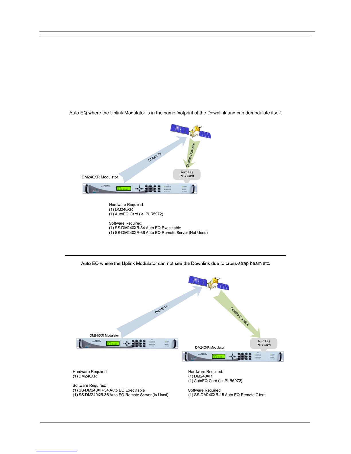
D.3 AutoEQ™ PIIC Interface Theory of Operation
AutoEQ™ PIIC Interface allows the ability to compensate for the overall system Group Delay
and Amplitude Equalization over the satellite by pre-distorting the Uplink Carrier, eliminating the
need for external Group Delay/Amplitude Equalizers. AutoEQ™ will automatically generate the
proprietary profile for the DM240XR to pre-distort the modulator, resulting in Amplitude and
Group Delay equalization over the Satellite Link.
Figure 1. Auto EQ PIIC Card Usage
MN-DM240XR– Revision 12 D–2
Page 9
DM240XR High-Speed Digital Modulator AutoEQ™ Interface Operation Guide
AutoEQ™ supports SCPC equalization of Group Delay and Amplitude over the satellite system.
When installed into the PIIC slot of the DM240XR (with Firmware Revision FO5377-J or
higher), the AutoEQ™ Calibration menu will be displayed allowing for selection and monitoring
of the AutoEQ™ functions. The AutoEQ™ will operate over the full transponder from a symbol
rate of 10.1 Msps to 45 Msps.
Note, the 45 Msps AutoEQ™ requires a different PIIC card (PLR5972) than the original PIIC
card (PLR5808) operating to 38 Msps. The new AutoEQ™ card supersedes and replaces the
original one and both are supported by revision N or later firmware.
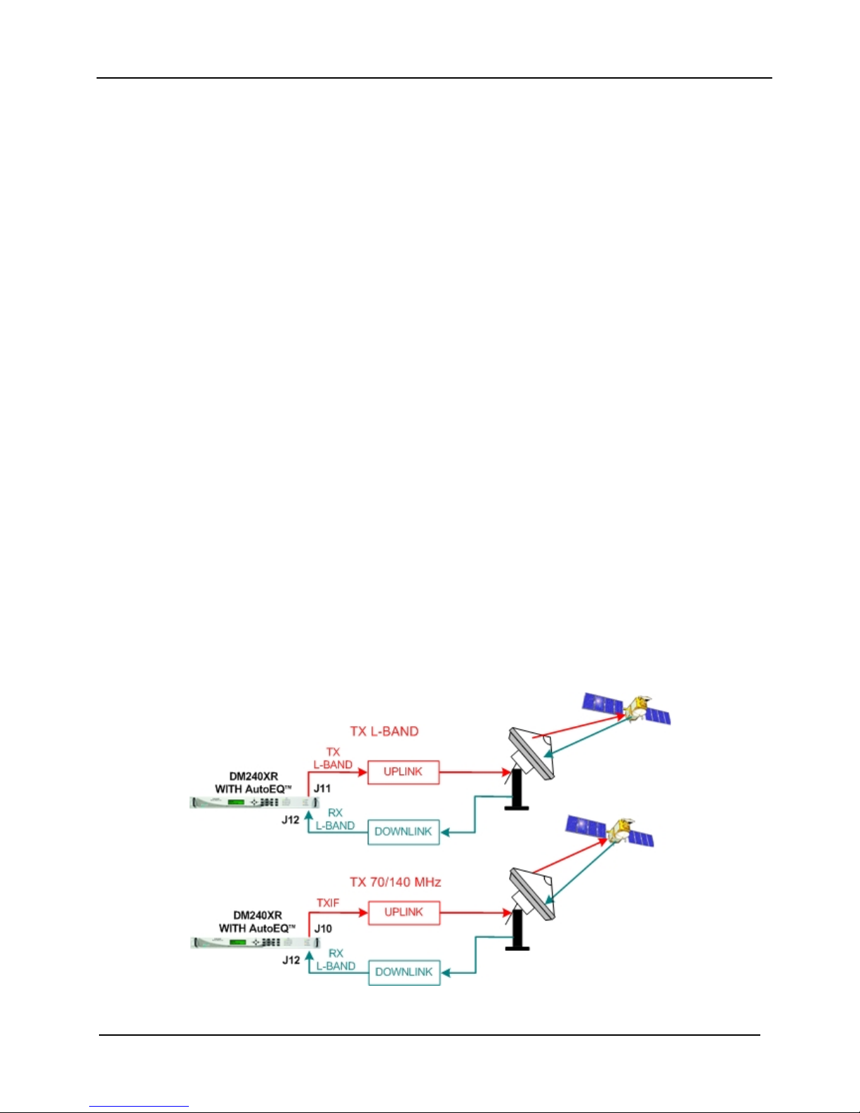
When the AutoEQ™ Calibration mode is selected, the DM240XR will disable the existing
programmed modulated outbound signal, and replace it with the AutoEQ™ calibration signal at
the same Symbol Rate, Roll off, and Transmit frequency as programmed into the DM240XR.
This signal is transmitted to the satellite, and received (Satellite Loop-Back) by the DM240XR
AutoEQ™ input at the L-Band downlink frequency. The AutoEQ™ calibration mode will
demodulate the received signal, and automatically calculate the required pre-distortion parameters
for the Satellite Link.
This information is read by the DM240XR modulator where the new pre-distort values are
programmed into the outbound carrier, resulting with the required pre-distortion of the TX output.
Upon successful completion of the calibration cycles, the DM240XR will automatically return to
the programmed outbound signal (such as DVB-S2) with the proper pre-distortion for the satellite
loop per the selected symbol rate, roll off and transponder frequency. If any parameters are
changed affecting Symbol Rate or Roll off, AutoEQ™ must be re-calibrated to the new
parameters. At any time, AutoEQ™ can be enabled or disabled.
The DM240XR is capable of retaining 32 AutoEQ™ satellite loop pre-distortion values, which
can be useful for systems requiring relocation to different transponders or Satellites. Once the
applicable transponder is calibrated, the calibration information can be stored in memory for use
now or in the future. All storage locations can be renamed by the user to correspond with the
identification of the transponder, and recalled for operational use.
Figure 2 AutoEQ™ Satellite Loopback
MN-DM240XR– Revision 12 D–3
Page 10
DM240XR High-Speed Digital Modulator AutoEQ™ Interface Operation Guide
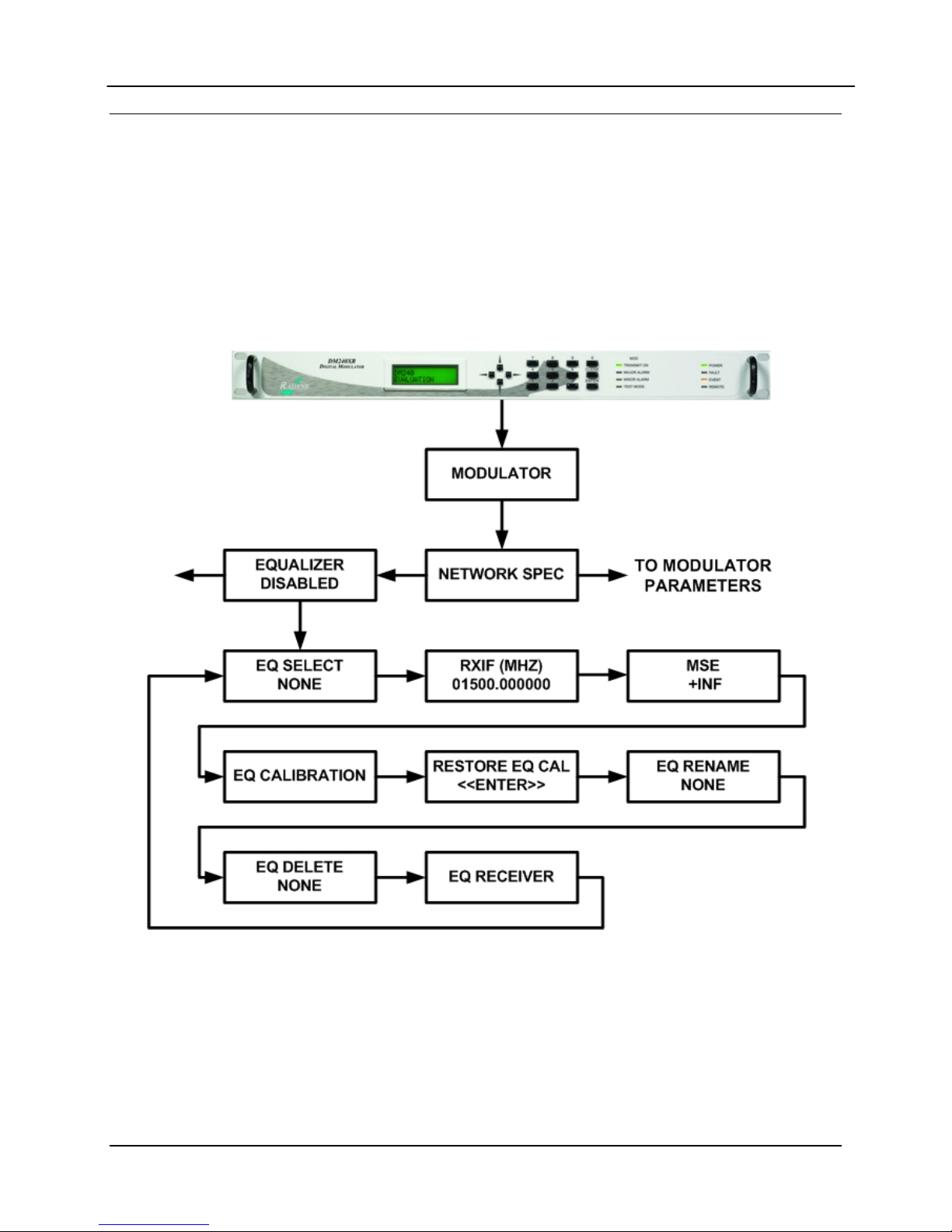
D.4 AutoEQ™ Menu Options and Parameters
These Menu options are only available when the DM240XR is configured for AutoEQ™
operation. Refer to Figure 3 for the AutoEQ™ portion of the DM240XR Menu Tree. The
DM240XR must have software Version FO5377-J or higher to operate the AutoEQ™ PIIC
Interface Card. These Menu options are also available on the Ethernet Web browser (J6), the
RS232 (J1) terminal port, and the Remote Port (J4) of the DM240XR. Refer to the DM240XR
Manual for all Modulator related options and Parameters.
Figure 3 AutoEQ™ Menu Tree
MN-DM240XR– Revision 12 D–4
Page 11

DM240XR High-Speed Digital Modulator AutoEQ™ Interface Operation Guide
EQ ENABLE: {Enable, Disable}
Allows the DM240XR Modulator to implement the AutoEQ™
coefficient values as specified by the EQ Select.
EQ SELECT: {None, User Specified Name}
Allows the DM240XR Modulator to select the stored AutoEQ™
coefficient file to be implemented. Up to 32 User Nameable
storage locations are available.
RXIF: {950 – 2050 MHz}
Sets the receive input center frequency for the AutoEQ™
Interface Card. This programmed frequency must be within +
25
kHz of the actual desired system downlink center frequency to
insure proper acquisition.
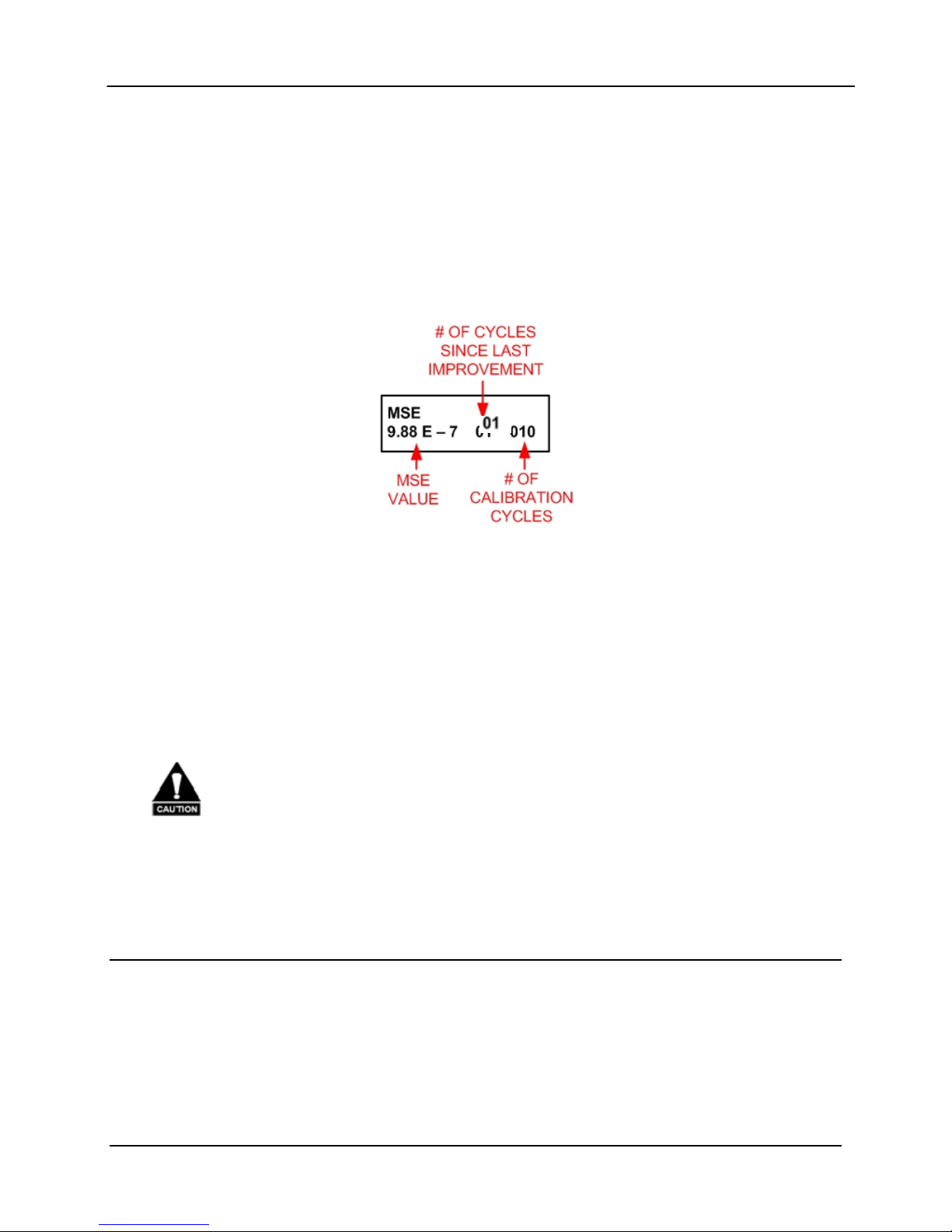
MSE: {Value}
Displays the Mean Squared Error (MSE) value of the equalizer.
A value of 1 E-5 or less indicates a successful calibration run
with acceptable coefficients for operation over the satellite.
EQ CAL: {Normal, Calibrating, Ref ACQ}
Allows the DM240XR Modulator to select the AutoEQ™
interface mode of operation.
Normal: When in this state, the AutoEQ™ is in monitoring
mode, with no Calibration or Reference Acquisition functions
being preformed.
Calibrating: When in this state, the AutoEQ™ will program the
DM240XR modulated output for the AutoEQ™ calibration
signal. The calibration output bandwidth is set by the symbol
rate currently programmed into the DM240XR Modulator.
During calibration, the AutoEQ™ will compute the coefficient
values required to successful equalize the group delay and
amplitude of the satellite link over the programmed symbol rate.
During this process, the MSE can be monitored reflecting the
calibration process. Upon successful completion of the
calibration, the EQ CAL will revert to the “Normal” state, and
the event log of the DM240XR will reflect “AutoEQ™ CAL
SUCCESSFUL”.
MN-DM240XR– Revision 12 D–5
Page 12

DM240XR High-Speed Digital Modulator AutoEQ™ Interface Operation Guide
(EQ CAL: Cont)
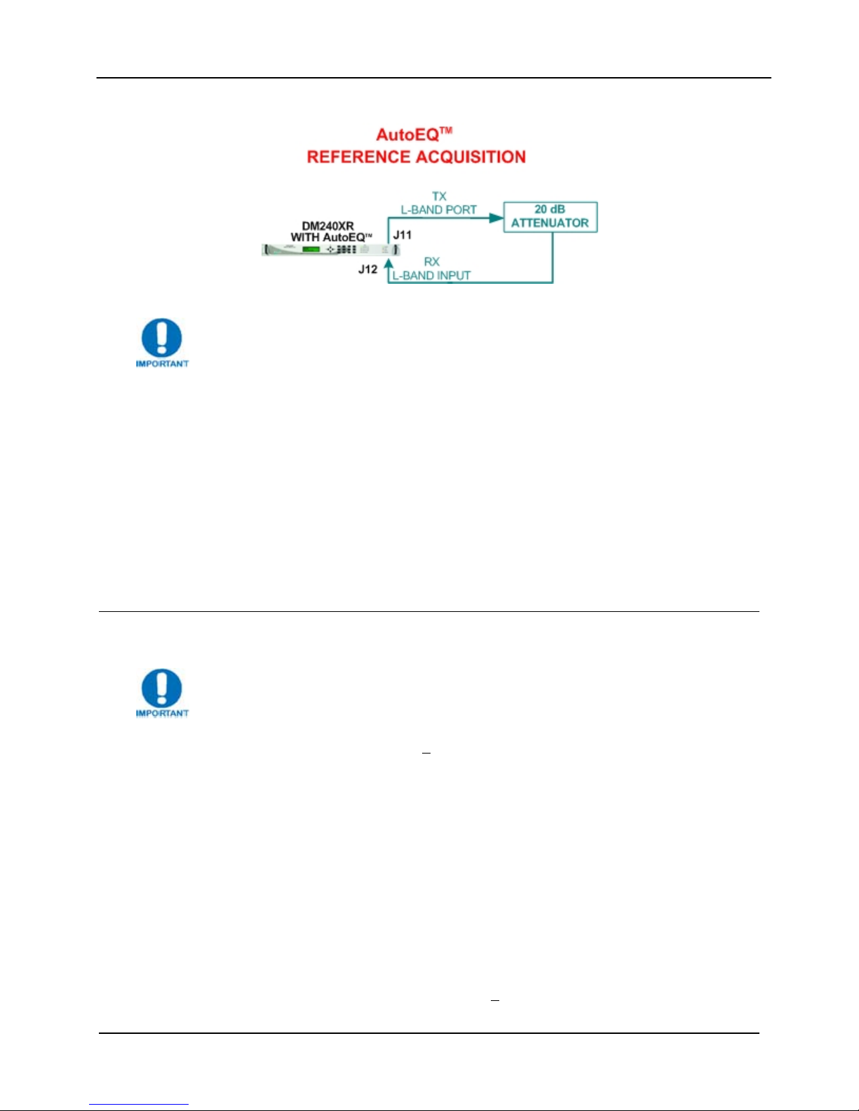
REF ACQ: Although default reference files are provided, the
operator may wish to acquire the best possible reference from
their modulator. A mechanism to accomplish this is allowed by
REF ACQ, this overwrites the stored default and replaces it with
a new reference. Prior to entering this state, the L-Band output
of the DM240XR (J11) must be connected to the AutoEQ™
RXRF Input (J12). The DM240XR Output power should be set
to -20 dBm, and a 20 dB in line attenuator should be used. The
Modulator output frequency should be set to set to the
corresponding AutoEQ™ RXRF Input Frequency. When
properly connected and in this state, the AutoEQ™ will program
the DM240XR modulated output for the AutoEQ™ calibration
signal. The calibration output bandwidth is set by the symbol
rate currently programmed into the DM240XR Modulator.
During reference calibration, the AutoEQ™ will obtain receive
lock and establish the baseline coefficients for internal reference.
References are captured for each modulator roll-off and
oversample rate. During this process, the MSE can be monitored
reflecting the Reference Acquisition process. Upon successful
completion of the Reference Acquisition, the REF ACQ will
revert to the “Normal” state, and the event log of the DM240XR
will reflect “REF ACQ SUCCESSFUL”.
RESTORE EQ CAL: {Filename}
Allows the selected Calibration coefficient file to be Restored.
EQ RENAME: {Filename}
Allows the Calibration coefficient file to be renamed using
Alpha-numeric characters.
EQ DELETE: {Filename}
Allows the selected Calibration coefficient file to be deleted.
EQ RECEIVER: {Local, Remote}
Allows selection of Local or Remote Equalization.
MN-DM240XR– Revision 12 D–6
Page 13
DM240XR High-Speed Digital Modulator AutoEQ™ Interface Operation Guide
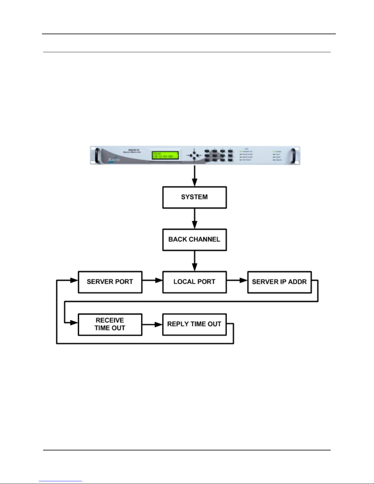
D.5 AutoEQ™ Back Channel Menu Options and Parameters
These Menu options are only available when the DM240XR is configured for AutoEQ™
operation. Refer to Figure 4 for the back channel portion of the DM240XR Menu Tree. The
DM240XR must have software Version FO5377-J or higher to operate the AutoEQ™ PIIC
Interface Card. These Menu options are also available on the Ethernet Web browser (J6), the
RS232 (J1) terminal port, and the Remote Port (J4) of the DM240XR. Refer to the DM240XR
Manual for all Modulator related options and Parameters.
Figure 4. AutoEQ™ Back Channel Menu Tree
MN-DM240XR– Revision 12 D–7
Page 14

DM240XR High-Speed Digital Modulator AutoEQ™ Interface Operation Guide
D.6 AutoEQ Backchannel Setup
Introduction
To support remote equalization with the AutoEQ system, the equalization data is
transported over TCP/IP using a backchannel protocol. Before setting up the
backchannel, perform the TCP/IP Ethernet setup as outlined in the TCP/IP Ethernet Setup
section of the user manual. This document is to be used only as a guideline for setting up
the backchannel menus. Contact the Network administrator for proper guidance and
support to ensure setup is successful.
Backchannel Configuration
Using the Front Panel display and arrow keys, scroll thru the System menu until the
Backchannel sub menu is displayed. Both the local unit (the Modulator) and the remote
unit (with the AutoEQ card installed) require the proper configuration with the correct
network settings.
Refer to Figure 4.
Note: The router/gateway/firewall system must be configured to allow these ports to
pass on each communication end. Contact your Network Administrator for allowable
port numbers and to open up the ports on the firewall if necessary.
Enter into the Backchannel menu and the following sub menus will appear, however the
order may vary.
LOCAL PORT: {XXXX}
The local port number must be set to the same value at
both the local and remote sites.
SERVER PORT: {XXXX}
The server port number must be set to the same value at
both the local and remote sites.
Note: The local port and server port values must be different from the local and remote
sites.
SERVER IP ADDR: {XXX.XXX.XXX.XXX} Hexidecimal Address
{ddd.ddd.ddd.ddd} Decimal Address
On the local unit, this should have the value of the
remote unit’s IP address.
Note: If the remote IP address is not publicly accessible then its translated NAT
(Network Address Translation) needs to be applied.
RECEIVE TIMEOUT: {X.X MINUTES}
This value is factory set, and should only be adjusted as directed by your Network
administrator or Radyne Customer Service.
REPLY TIMEOUT: {XX secs}
This value is factory set, and should only be adjusted as directed by your Network
administrator or Radyne Customer Service.
MN-DM240XR– Revision 12 D–8
Page 15

DM240XR High-Speed Digital Modulator AutoEQ™ Interface Operation Guide
Figure 5. AutoEQ™ Backchannel Setup
Back Channel Test
The "BACK CHAN TEST" does the following:
1. Establishes a connection with the back channel server as defined under the
SYSTEM->BACK CHANNEL menu.
2. Issues a ping to the back channel server.
3. Sends a message to and validates the reply from the back channel server application
running on the back channel server.
4. If passes, no additional; events will appear in the event log.
5. If fails, logs one of the following events on the local side event log:
a. "BACK CHANNEL TEST: FAILED PING"
b. "BACK CHANNEL TEST: FAILED BACK CHAN SERVICE REQ"
c. "BACK CHANNEL TEST: REPLY FORMAT ERROR"
d. "BACK CHANNEL TEST: ERROR REPLY"
6. If fails, may log one of the following events on the server side event log:
a. "INVALID CHANNEL TEST SIZE"
b. "INVALID CHANNEL TEST PAYLOAD"
Ethernet Test
Verify Local Router:
On the local unit, using the Front Panel display and arrow keys, scroll thru the Monitor
menu and clear the Event Log.
Now scroll thru the Test menu and Ping Test the TCP/IP ROUTER. If the event LED on
the front panel does not light, communications between the modem and its router was
successful.
Verify Remote Router:
Perform the same test on the remote unit as detailed under Verify Local Router.
Verify Local to Remote Connection:
On the local unit, using the Front Panel display and arrow keys, scroll thru the Monitor
menu and clear the Event Log.
Now scroll thru the Test menu and Ping Test the BK CHAN SERVER. If the event LED
on the front panel does not light, communications between the local modem and the
remote modem was successful.
MN-DM240XR– Revision 12 D–9
Page 16

DM240XR High-Speed Digital Modulator AutoEQ™ Interface Operation Guide
D.7 AutoEQ™ Operation Procedure
The following sequence must be followed in order to perform the initial AutoEQ™ Calibration.
The sequence is identified into three (3) individual sections: 1) Reference Acquisition
Calibration (REF ACQ) - optional, 2) Equalizer Calibration (CALIBRATING), and 3) Equalizer
Modes (NORMAL). These three menu selections are selectable under EQ CAL.
All DM240XR Faults and Alarms must be cleared prior to any AutoEQ™
Calibration process. If Data is not present on the DM240XR Data interface
causing a data Alarm, Advanced ASI may be selected for the AutoEQ™
Calibration (Advanced ASI inserts Null Packets into the Data Stream).
D.8 Reference Acquisition Calibration (Optional Step)
This Section will establish the calibration reference for the AutoEQ™ Interface Card. This
optional step may be preformed prior to Equalizer Calibration. This step is optional as
default reference(s) are already loaded into the system. This operation will replace the
default reference(s) with the actual references measured during the calibration cycle. The
modulator must be programmed for an L-Band frequency and the AutoEQ
Frequency programmed to match.
™
RXIF
1. Install the AutoEQ™ PIIC Interface into one of the available PIIC Slots on the DM240XR.
2. Verify that the DM240XR revision is FO5377-K or greater.
3. Insure that there is a Flash Card installed in the Flash Card slot on the DM240XR.
4. Using the Front Panel menu, set the DM240XR Modulator Data Rate, Modulation type, Roll
off, and remaining Modulator parameters to the required system settings.
5. Using the Front Panel menu, scroll to “RXIF” located under the EQUALIZER menu and set
the AutoEQ “RXIF”.
For best results it is suggested that the RXIF frequency used to acquire the
reference be the actual frequency used to perform the equalization calibration.
6. Using the Front Panel menu, set the DM240XR Transmit Frequency (L-Band) to match the
programmed AutoEQ RXIF Frequency.
7. Using the Front Panel menu, set the DM240XR TX Output Power to -10 dBm.
8. Connect the DM240XR L-BAND Output (J11) through a 20 dB attenuator then to the AutoEQ
Interface RXRF Input (J12) using a suitable L-Band Cable.
MN-DM240XR– Revision 12 D–10
Page 17
DM240XR High-Speed Digital Modulator AutoEQ™ Interface Operation Guide
Figure 6. AutoEQ™ Ref Acq Set-up
For best results place the attenuator pad as close to the AutoEQ port (J12) as
possible.
9. Clear the events of the modulator by scrolling to <MONITOR> then down and over to <PRESS
CLEAR TO ERASE EVENTS> and press clear. Verify that the Event LED is now off.
10. Using the Front Panel menu, scroll to “EQ CALIBRATION” and set to “REF ACQ”
a. After a successful calibration the event log will display “REF ACQ SUCCESSFUL” upon
completion of this step. When the REF ACQ is complete, the “EQ CALIBRATION” will
revert to “NORMAL”.
11. Remove the interconnect cable installed in Step 8 above.
12. Verify through the event log that the system successfully calibrated the reference.
D.9 Equalizer Calibration
For best AutoEQ equalization calibration it is recommended that the amplifier be
run in its linear range and not saturated.
The AutoEQ™ RXRF Acquisition range is +
programmable. To insure proper operation, the actual center frequency of the carrier should be
accurately measured with this measured value programmed into the AutoEQ™. This can be
accomplished by generation a CW (Carrier Wave) frequency with the modulator, and measuring
the downlink L-Band frequency with an accurate frequency counter or spectrum analyzer.
1. Reprogram the DM240XR Modulator output frequency to the proper operating frequency of
the Uplink system (if it was reprogrammed for Section 4.1 above) and the output power to the
system operating level. Connect the DM240XR Modulator output to the Uplink system.
Enable the modulator and adjust all uplink parameters as required for proper uplink
operation.
25 kHz from the programmed frequency and is not
2. Measure the center frequency of the down converted modulated signal. Using the front panel
Menu, reprogram the AutoEQ™ to the center frequency of the down converted signal. The
AutoEQ™ programmed frequency must be within +
MN-DM240XR– Revision 12 D–11
25 kHz of the measured frequency in
Page 18
DM240XR High-Speed Digital Modulator AutoEQ™ Interface Operation Guide
order to assure proper acquisition of the downlink signal. Connect the AutoEQ™ Input (J12)
to the earth Station L-Band Downlink System. The desired downlink carrier should be
typically between the range of -45 to -20 dBm.
3. Clear the events of the modulator by scrolling to <MONITOR> then down and over to
<PRESS CLEAR TO ERASE EVENTS> and press clear. Verify that the Event LED is now
off.
4. Using the Front Panel menu, scroll to “EQ CAL” and set it to “CALIBRATING”. This will
start the AutoEQ™ Calibration for the Satellite Link.
a. After each data acquisition and processing cycle the MSE display will be updated. A normal
calibration cycle will take 60 to 90 seconds, and system typically performs two or three of
these cycles.
b. During this calibration, the MSE can be monitored showing the progress of the cycle. A
value of 1 E-5 or less will reflect a success full completion of this step. Additionally, event
light will come on, and the event log will display “EQ CAL SUCCESSFUL” upon
completion of this step. When the EQ CAL is complete, the “EQ CAL” will revert to
“NORMAL” and the AutoEQ file will be named “UNTITLED”.
The AutoEQ calibration must be saved or powering down of the system will lose
the calibration.
5. To change the name of the “UNTITLED” file, using the Front Panel menu, scroll to EQ
RENAME, Press ENTER, use the Up/DN Arrows on the Keyboard to change the name, and press
ENTER to save the new name for the file.
6. Using the Front Panel menu, scroll to “SAVE EQ CAL”, and press ENTER to save the file.
D.10 Equalizer Modes
The AutoEQ feature must be enabled on the DM240XR, and section 4.2 Equalizer Calibration
must be performed prior to this section.
Disable Mode
MN-DM240XR– Revision 12 D–12
Page 19
DM240XR High-Speed Digital Modulator AutoEQ™ Interface Operation Guide
To disable a programmed Equalizer Setting, use the Front Panel and scroll to “EQUALIZER”,
press the Enter” key, change the selection to “DISABLE”, and press the Enter key. This will
disable the Equalizer, and allow for normal operation of the DM240XR.
Enable Mode
To enable the equalizer, use the front panel and scroll to “EQ SELECT” and press the Enter key.
Using the Up/Dn keys, scroll to the desired saved equalizer file, and press the Enter key to select
the file. Scroll back to Equalizer, press the Enter key, and using the Up/Dn keys, scroll to
“ENABLE” and press the Enter key. This will enter the selected equalizer file parameters into
the DM240XR Modulator and initiate AutoEQ™ equalization.
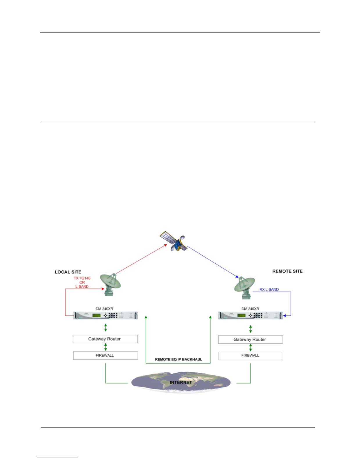
D.11 AutoEQ™ Remote Operation
To operate the AutoEQ™ system in remote, perform the following setup steps.
1. The TCP/IP Ethernet Setup described in the operator manual
2. The Backchannel Setup as described in Section 4.0
3. Select REMOTE under the EQ RECEIVER Submenu
4. Perform the Operations as described in Section 5.0 for equalization
Figure 7. Remote AutoEQ™ Site Equalization
MN-DM240XR– Revision 12 D–13
Page 20

DM240XR High-Speed Digital Modulator AutoEQ™ Interface Operation Guide
D.12 Additional Features
D.12.1 AutoEQ™ Status Indicator
The LED on the back of the AutoEQ™ interface card can provide additional status for the
operation of the AutoEQ™ system.
Short Blink Green Heartbeat, board ready for operation.
Solid Green AutoEQ™ test pattern lock.
Solid Yellow AutoEQ™ data being accessed.
Blink Red AutoEQ™ test pattern unlocked. Signal error.
D.12.2 LNB Power Connector
On the back of the AutoEQ™ interface card is the connector J13 that can be used to insert LNB
power to the J12 SMA connector to feed DC to the LNB.
Mating Connector: PP3-002A 5.5mm x 2.1mm x 9.5mm In-Line DC Power Plug.
(www.cui.com)
MN-DM240XR– Revision 12 D–14
Page 21
ER-DM240XR-EB12 THIS DOCUMENT IS NOT SUBJECT TO REVISION/UPDATE! PLM CO C-0023872 Page 1 of 2
Errata B
Comtech EF Data Documentation Update
Subject:
Revise Chapter 7. Technical Specifications – Update DM240XR IF Frequency
Specification
Date :
Per PLM System
Original Manual
Part Number/Rev:
MN-DM240XR Rev 12
Errata Number/
PLM Document
ID:
ER-DM240XR-EB12
PLM CO Number:
C-0023872
Comments:
The information provided in this erratum will be incorporated into the next
formal revision of the manual.
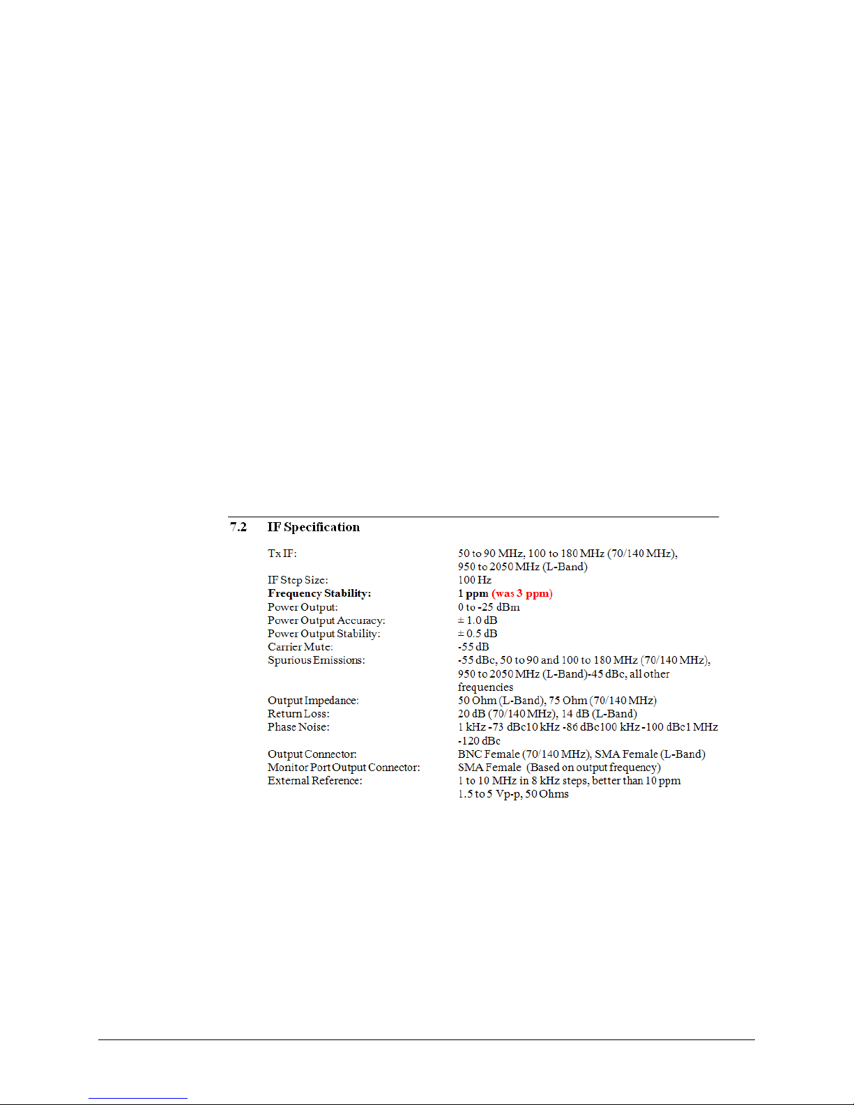
Revise Sect. 7.2 IF Specification / Frequency Stability (page 7-1):
Page 22

Errata C for MN-DM240XR Rev 12
/
p
Errata C
Comtech EF Data Documentation Update
Subject:
Revise Chapter 9. Rem ote Operations – Add Auto EQ data
Date :
Original Manual
Part Number/Rev:
Errata Number
PLM Document
PL M CO Number:
Comments: The informat ion
Per PLM System
MN-DM240XR Rev 12
ER-DM240XR-EC12
ID:
C-0024011
formal revision of the manual.
See attached pages for Chapter 9.
rovided in this erratum will be inc or por ated into the next
ER-DM240XR-EC12
Page 23

Errata C for MN-DM240XR Rev 12
Blank Page
ER-DM240XR-EC12
Page 24

DM240XR High-Speed Digital Modulator Remote Operations
e
m
d
Source
<1> Reserved TBD, Default = 0
<11> Reserved TBD
<1> Reserved TBD
<1> Major Alarm
Mask
Bit 0 = Spar
Bit 1 = Transmit Oversample PLL Lock
Bit 2 = FPGA Config Error
Bit 3 = IF Synthesizer PLL Lock
Bit 4 = External Reference PLL Lock
Bit 5 = Composite (SCT) PLL Lock
Bit 6 = Symbol PLL Lock
Bit 7 = Spare
0 = Mask, 1 = Allow
<1> Minor Alarm
Mask
Bit 0 = Terrestrial Ethernet data activity detect
Bit 1 = Loss Terrestrial Clock
Bit 2 = Loss Terrestrial Data
Bit 3 = FIFO Error
Bit 4 = Output Level
Bit 5 = Terrestrial Framing Error
Bit 6 = Terr Ethernet jitter buffer underflow
Bit 7 = Terr Ethernet jitter buffer overflow
0 = Mask, 1 = Allow
<1> Common Fault
Mask
Bit 0 = -12 V Alar
Bit 1 = +12 V Alarm
Bit 2 = +5 V Alarm
Bit 3 = Spare
Bit 4 = Spare
Bit 5 = Spare
Bit 6 = Spare
Bit 7 = Spare
0 = Mask, 1 = Allow
<1> Reserved TBD, Default = 0
<4> Symbol Rate Symbol Rate in Symbols Per Secon
<1> Terrestrial
Framing
<1> Roll Off 0 = 0.35, 25 = 0.25, 1 = 0.20
<1> Reserved TBD
<1> Output Clock
Source
<1> Network Spec 0 = DVB-S
MN-DM240XR– Revision 12 9–5
0 = 188 Byte, 1 = 204 Byte, 2 = No Framing
5 = COP3, 6 = ACM, 7 = Bridge
TE, 1 = SCT, 2 = None
9 = DirecTV
11 = DVB-S2 CCM
13 = Only DirecTV
15 = DVB-S2 ACM
Page 25

DM240XR High-Speed Digital Modulator Remote Operations
–
n
n
n
<1> BB Scrambler
0 = Normal, 1 = Bypass
Bypass
<1> Outer FEC
0 = Normal, 1 = Bypass
Bypass
<1> Test Pattern 0 = None, 1 = 2
<1> Last Rate
0 = Symbol Rate, 1 = Data Rate, 2 = Auto
Control
<1> Interleaver
0 = Bypass, 1 = Normal
Bypass
<1> PCR
0 = Off, 1= O
Restamping
<1> Multi-PIIC
Mode
1 = Manual,
2 = Redundancy
<1> Redundancy
Mode
0 = Force Prime,
1 = Force Backup,
2 = Manual Revert,
3 = Auto-Revert
<1> Prime PIIC Slot 1 – 3
15
1, 23 = 223-1
<1> Backup PIIC
1 – 3
Slot
<1> Pilot Symbols 0 = Off, 1= O
<1> Inner FEC
0 = Normal, 1 = Bypass
Bypass
<1> PL Scrambler
0 = Normal, 1 = Bypass
Bypass
<1> Reserved Set to 0
<1> Reserved Set to 1
<2> Reserved Set to 0
<4> Gold Code Seq
0 to 262142
Index
<1> Sat Framing 3=DVB-S, 5=DTV, 10=DVB-S2 Normal, 15=DVB-S2 Short
<1> Auto EQ
0=Off, 1=O
Enable
<9> Auto EQ Filter
Coef Name
8-character NULL terminated string, this is the filter’s name
as shown on the front panel (identical to the filter’s base
fil e name, th e ex tension is ass umed to be “ AE Q”)
<1> Reserved
<1> Reserved
MN-DM240XR– Revision 12 9–6
Status Bytes
Page 26
DM240XR High-Speed Digital Modulator Remote Operations
n
n
E
E
E
<1> Redundancy
Mode
0 = Force Prime,
1 = Force Backup,
2 = Manual Revert,
3 = Auto-Revert
<1> Prime PIIC Slot 1 – 3
<1> Backup PIIC
1 – 3
Slot
<1> P ilot Symbols 0 = Off, 1= O
<1> Inner FEC
0 = Normal, 1 = Bypass
Bypass
<1> PL Scrambler
0 = Normal, 1 = Bypass
Bypass
<1> Reserved Set to 0
<1> Reserved Set to 1
<2> Reserved Set to 0
<4> Gold Code Seq
0 to 262142
Index
<1> Sat Framing 3=DVB-S, 5=DTV, 10=DVB-S2 Normal, 15=DVB-S2 Short
<1> Auto EQ
0=Off, 1=O
Enable
<9> Auto EQ Filter
Coef Name
8-character NULL terminated string, this is the filter’s name
as shown on the front panel (identical to the filter’s base
fil e name, th e ex tension is ass umed to be “ AE Q”)
DM240XR Clock Source Selection Matrix
Interface T ype InClk Source OutClk Source
RS-422 Serial SCT or SCT
SCT Only
G.703 (E3, T3, STS-1) SCT E Only SCT , SCTE, or None
HSSI SCT or SCT
SCT Only
OC3 SCTE Only None
STM-1 SCTE Only None
ASI, Advanced ASI SCTE Only None
M2P Parallel SCT or SCT
SCT Only
DVB Parallel SCTE Only SCT Only
MN-DM240XR– Revision 12 9–19
Page 27

DM240XR High-Speed Digital Modulator Remote Operations
When changing Data Rate, Symbol Rate, Inner FEC Rate, Modulation Type,
or Terrestrial Framing using the Mod All Command, the Data Rate and
Symbol R ate p aramet er must be ra nge checked us ing the fo llo wi ng formu la s
to ensur e t hey d o no t exceed t he max l i mi t s :
Symbol Rate = (Data Rate * Over head)/(Code Rate * Modulation)
Data Rate = (Symbol Rate * Code Rate * Mod ulat ion)/Overhead
Maximum Symbol Rate 68 Msps.
Maximum Data Rate 238 Mbps with high-speed interface card.
Overhead 204/188 for 188 byte
204/204 for 204 byte
204/187 for none
Modulation QPSK = 2, 16QAM = 4, BPSK = 1, 8PSK = 3
Code Rate 1/4, 1/3, 2/5, 3/5, 1/2, 2/3, 3/4, 5/6, 6/7, 7/8, 8/9, 9/10
MN-DM240XR– Revision 12 9–20
Page 28

Errata B for M N-DM240XR Rev 12 Rev ise DM24 0XR IF Frequen cy S tabi lity Spe cifi cati on
ER-DM240XR-EB12 THIS DOCUMENT IS NOT SUBJECT TO REVISION/UPDATE! PLM CO C-0023872 Page 2 of 2
This page is intentionally blank.
Page 29

Table of Contents
TABLE OF CONTENTS .............................................................................................................. III
CHAPTER 1. INTRODUCTION ................................................................................... 1–1
1.1 Description ................................................................................................................................... 1–1
CHAPTER 2. INSTALLATION .................................................................................... 2–1
2.1 Installation Requirements .......................................................................................................... 2–1
2.2 Unpacking .................................................................................................................................... 2–2
2.3 Removal and Assembly ............................................................................................................... 2–2
2.4 Mounting Considerations ........................................................................................................... 2–2
2.5 Modulator Checkout ................................................................................................................... 2–3
2.5.1 Initial Power-Up .................................................................................................................... 2–3
CHAPTER 3. THEORY OF OPERATION ................................................................... 3–1
3.1 Theory of Operation ................................................................................................................... 3–1
3.2 DVB-S Operation ........................................................................................................................ 3–1
3.3 DVB-S2-BS-NBC Operation ...................................................................................................... 3–2
CHAPTER 4. USER INTERFACES ............................................................................. 4–1
4.1 User Interfaces ............................................................................................................................ 4–1
4.2 Front Panel User Interface ......................................................................................................... 4–1
4.2.1 Front Panel LCD Display ...................................................................................................... 4–2
4.2.2 Front Panel LED Indicators .................................................................................................. 4–2
4.2.3 Front Panel Keypad ............................................................................................................... 4–2
4.2.4 Parameter Setup .................................................................................................................... 4–3
4.3 Front Panel Control Screen Menus ........................................................................................... 4–5
4.3.1 Main Menus .......................................................................................................................... 4–5
4.3.2 Modulator Menu Options and Parameters ............................................................................ 4–6
4.3.3 Interface Menu Opt ions and Parameters ............................................................................... 4–9
4.3.3.1 Plug-In Interface Card (PIIC) ......................................................................................... 4–10
4.3.3.2 Ethernet Interface (J1) ..................................................................................................... 4–12
4.3.4 RF Switch Menu Options and Parameters .......................................................................... 4–20
4.3.5 Monitor Menu Options and Parameters .............................................................................. 4–20
4.3.6 Alarms Menu Optio ns and Parameters ............................................................................... 4–20
iii
Page 30

Table of Contents Revision 12
DM240XR High-Speed Digital Modulator MN-DM240XR
4.3.7 System Menu Options and Parameters ............................................................................... 4–22
4.3.8 Test Menu Option s and Parameters .................................................................................... 4–30
4.4 Remote Port User Interface ..................................................................................................... 4–30
4.4.1 Protocol Structure ............................................................................................................... 4–31
4.4.2 Protocol Wrapper ................................................................................................................ 4–31
4.4.3 Frame Description and Bus Handshaking ........................................................................... 4–34
4.4.4 Global Response Operational Codes ................................................................................... 4–34
4.4.5 Collision Avoidance ............................................................................................................ 4–36
4.4.6 Software Compatibility ....................................................................................................... 4–37
4.4.7 RLLP Summary .................................................................................................................. 4–38
4.4.8 DM240XR Opcode Command Set ..................................................................................... 4–38
4.5 Ethernet Port User Interface ................................................................................................... 4–39
4.6 Simple Network Management Protocol (SNMP) ................................................................... 4–39
4.7 The Management Information Base (MIB) ............................................................................ 4–39
4.7.1 Directory {internet 1} 1.3.6.1.1 ........................................................................................ 4–39
4.7.2 Mgmt {internet 2} 1.3.6.1.2 ............................................................................................. 4–39
4.7.3 Experimental {internet 3} 1.3.6.1.3 ................................................................................... 4–39
4.7.4 Private {internet 4} 1.3.6.1.4 ............................................................................................ 4–40
4.8 Terminal Port User Interface ................................................................................................... 4–41
4.8.1 Connecting the Terminal ..................................................................................................... 4–42
4.8.2 Terminal Screens ................................................................................................................ 4–42
CHAPTER 5. REAR PANEL INTERFACES ............................................................... 5–1
5.1 DM240XR Connections .............................................................................................................. 5–1
5.2 AC Power ..................................................................................................................................... 5–3
5.3 Compact Flash Interface (J5) ..................................................................................................... 5–3
5.3.1 Feature Upgrade .................................................................................................................... 5–3
5.3.2 Firmware Update .................................................................................................................. 5–3
5.3.3 Custom Configuration ........................................................................................................... 5–4
5.4 Ethernet Interface (J6) ............................................................................................................... 5–4
5.5 External Reference (Input) ........................................................................................................ 5–4
5.6 Remote Port (I/O) ....................................................................................................................... 5–4
5.7 Terminal Port (I/O) ................................................................
..................................................... 5–5
5.8 Alarm Port ................................................................................................................................... 5–5
5.9 IF Output Port (J10 & J11) ........................................................................................................ 5–6
5.9.1 Output Monitor Port (J9) ....................................................................................................... 5–6
iv
Page 31

Table of Contents Revision 12
DM240XR High-Speed Digital Modulator MN-DM240XR
5.10 RF Redundancy Switch Control (J2) ........................................................................................ 5–6
5.11 Built in ASI/Advanced ASI Interface (J7) ................................................................................ 5–6
5.12 Plug-In Interface Cards (PIICs) ................................................................................................ 5–7
5.12.1 ASI PIIC ................................................................................................................................ 5–7
5.12.1.1 ASI (Asynchrono us Serial Interface) ................................................................................ 5–7
5.12.1.2 AASI (Advanced Asy nchronous Serial Interface) ............................................................ 5–7
5.12.2 ASI Monitor .......................................................................................................................... 5–8
5.12.3 Parallel RS-422 Interface ...................................................................................................... 5–8
5.12.3.1 M2P (Parallel, RS-422) ..................................................................................................... 5–8
5.12.3.2 DVB (Parallel, RS-422) .................................................................................................... 5–9
5.12.4 Parallel LVDS Interface ...................................................................................................... 5–10
5.12.5 HSSI Interface ..................................................................................................................... 5–10
5.12.6 Ethernet 100/1000 Base-T Interface ................................................................................... 5–11
5.12.7 EIA-530 /RS-422 Serial Interface ....................................................................................... 5–11
5.12.8 G.703 Interface (Contact factory for avai lability) ............................................................... 5–12
CHAPTER 6. MAINTENANCE AND TROUBLESHOOTING ...................................... 6–1
6.1 Periodic Maintenance ................................................................................................................. 6–1
CHAPTER 7. TECHNICAL SPECIFICATIONS ........................................................... 7–1
7.1 Introduction ................................................................................................................................. 7–1
7.2 IF Specification ............................................................................................................................ 7–1
7.3 Baseband Specification ............................................................................................................... 7–2
7.3.1 DVB-S ................................................................................................................................... 7–2
7.3.2 DVB-S2-CCM (CCM - Normative) .................................................................................... 7–2
7.3.3 DVB-S2-ACM (Normative Features with Single Transports streams) ................................ 7–3
7.4 Interface Types Available (PIIC) ............................................................................................... 7–4
7.5 Monitor and Control ................................................................................................................... 7–4
7.6 Environmental ............................................................................................................................. 7–4
7.7 Physical ........................................................................................................................................ 7–5
7.8 Options ......................................................................................................................................... 7–5
7.9 DVB-S Series Configuration
7.9.1 DVB-S2 Series Configuration .............................................................................................. 7–5
7.10 Data Rates (DVB-S) .................................................................................................................... 7–5
7.10.1 Data Rates (DVB-S2)............................................................................................................ 7–7
CHAPTER 8. SNMP .................................................................................................... 8–1
...................................................................................................... 7–5
v
Page 32

Table of Contents Revision 12
DM240XR High-Speed Digital Modulator MN-DM240XR
CHAPTER 9. REMOTE OPERATIONS ....................................................................... 9–1
9.1 DM240XR Opcode Command Set ............................................................................................ 9–1
9.2 Modulator Command Set ........................................................................................................... 9–1
9.3 Detailed Command Descriptions ............................................................................................... 9–3
CHAPTER 10. WEB BROWSER ................................................................................. 10–1
10.1 Web Browser User Interface .................................................................................................... 10–1
10.2 Configuring Your PC ............................................................................................................... 10–2
10.2.1 LED Indicators .................................................................................................................... 10–3
10.3 GUI Screen Menus .................................................................................................................... 10–4
10.3.1 Introduction Menu .............................................................................................................. 10–5
10.3.1.1 Login Screen ................................................................................................................... 10–6
10.3.2 Password Setup ................................................................................................................... 10–7
10.3.3 IP and Application Administration ..................................................................................... 10–9
10.3.4 Monitor and Control Menu ............................................................................................... 10–14
10.3.4.1 Transmit Menu .............................................................................................................. 10–14
10.3.4.2 Interface Menu .............................................................................................................. 10–16
10.3.4.3 RFSWITCH Menu ........................................................................................................ 10–17
10.3.4.4 Monitor Menu ............................................................................................................... 10–17
10.3.4.5 Alarms Menu ................................................................................................................ 10–19
10.3.4.6 System Menu ................................................................................................................ 10–20
10.3.4.7 Test Menu ..................................................................................................................... 10–22
APPENDIX A. FRONT PANEL UPGRADE PROCEDURE ......................................... A–1
A.1 Introduction ................................................................................................................................ A–1
A.2 Required Equipment ................................................................................................................. A–1
A.3 Upgrade Procedure .................................................................................................................... A–1
A.4 Demonstrati on Procedure ......................................................................................................... A–3
A.4.1 Running in Demonstration Mode ......................................................................................... A–5
A.4.2 Canceling Demonstration Mode .......................................................................................... A–6
APPENDIX B. TCP/IP ETHERNET SETUP ................................................................. B–1
B.1 Introduction ................................................................................................................................ B–1
B.2 TCP/IP Network Configuration ............................................................................................... B–1
B.3 Network Configuration Summary ................................................................
............................ B–3
B.4 Ethernet Test .............................................................................................................................. B–3
vi
Page 33

Table of Contents Revision 12
DM240XR High-Speed Digital Modulator MN-DM240XR
B.4.1 Connecting the Modem Ethernet Cable to a Network Link ................................................. B–3
B.4.2 Connecting the Modem Ethernet Cable Directly to a Computer (without a Network) ........ B–4
B.4.3 Testing the Ethernet connection using the Ping Program (Optional) ................................... B–6
APPENDIX C. WEB BROWSER QUICK SETUP GUIDE ............................................ C–1
C.1 Introduction ................................................................................................................................ C–1
C.2 Web Users Configuration .......................................................................................................... C–2
C.2.1 Change Web User Name ...................................................................................................... C–3
C.2.2 Change Authentication Password ........................................................................................ C–3
C.2.3 Change Access Rights .......................................................................................................... C–4
C.3 Modem Web Site ........................................................................................................................ C–4
C.4 Web Page Appearance ............................................................................................................... C–5
APPENDIX D. AUTOEQ™ INTERFACE OPERATION GUID E .................................. D–1
D.1 Introduction ................................................................................................................................ D–1
D.2 Applicable Documents ............................................................................................................... D–1
D.3 AutoEQ™ PIIC Int erf ace Theory of Operation ..................................................................... D–1
D.4 AutoEQ
D.5 AutoEQ
™
Menu Options and Parameters ............................................................................... D–3
™
Back Channel Menu Options and Parameters ...................................................... D–6
D.6 AutoEQ Backchannel Setup ...................................................................................................... D–7
D.7 AutoEQ™ Operation Procedure .............................................................................................. D–9
D.8 Reference Acquisition Calibration (Optional Step) ................................................................ D–9
D.9 Equalizer Calibration .............................................................................................................. D–11
D.10 Equalizer Modes ....................................................................................................................... D–12
D.11 AutoEQ™ Remote Operation ................................................................................................. D–13
D.12 Additional Features ................................................................................................................. D–14
D.12.1 AutoEQ™ Status Indicator ................................................................................................ D–14
D.12.2 LNB Power Connector ....................................................................................................... D–14
vii
Page 34

Table of Contents Revision 12
DM240XR High-Speed Digital Modulator MN-DM240XR
Notes:
viii
Page 35

PREFACE
About this Manual
This manual describes the installation and operation for the Radyne DM240XR. This is a
technical document intended for earth station engineers, technicians, and operators responsible
for the operation and maintenance of the DM204XR.
Reporting Comments or Suggestions Concer ning this Manual
Comments and suggestions regarding the content and design of this manual are appreciated. To
submit comments, please contact the Comt ech E F Data Technical Publications department :
TechnicalPublications@comtechefdata.com
Conventions and Referenc es
Related Documents
The following documents are referenced in thi s m anual:
• EN300-421 and EN301-210 ETSI
• ETSI EN302-307
• INTELSAT Earth Station Standards IESS-308, -309, -310, and -315
• EUTELSAT SMS
Metric Conversion
Metric conversion information is located on the inside back cover of this manual. This information is
provided to assist the operator in cross-referencing non-Metric to Metric conversions.
Cautions and Warnings
i
Page 36

DM240XR Revision 12
CAUTION
CAUTION indicates a hazardous situation that, if not avoided, may result in
may also be used to indicate other
WARNING
indicates a potentially hazardous situation that, if not avoided,
IMPORTANT
Preface MN-DM240XR
IMPORTANT or NOTE indicates a statement associate d with the task
being performed or information critical for proper equipment function.
minor or moderate injury. CAUTION
unsafe practices or risks of property damage.
WARNING
could result in death or serious injury.
Examples of
Multi-Hazard Formats
Trademarks
Product names mentioned in this manual may be trademarks or registered trademarks of their
respective companies and are hereby acknowle dged.
ii
Page 37

DM240XR Revision 12
!
NOTE
Preface MN-DM240XR
Safety Compliance
EN 60950
Applicable testing is routinely performed as a condition of manufacturing on all units to ensure
compliance with safety requirements of EN60950.This equipment meets the Safety of Information
Technology Equipment specification as defined in EN60950.
Low Voltage Directive (LVD)
The following information is applicable for the E uropean Low Voltage Directive (EN60950):
<HAR> Type of power cord required for use in the European Community.
CAUTION: Double-pole/Neutral Fusing
ACHTUNG: Zweipolige bzw. Neutralleiter-Sicherung
International Symbols:
Symbol Definition Symbol Definition
~
Alternating Current
For additional symbols, refer to Cautions and Warnings, listed
earlier in this Preface.
Fuse
Protective Earth /
Safety Ground
Chassis Ground
iii
Page 38

DM240XR Revision 12
Preface MN-DM240XR
Warranty Policy
Comtech EF Data products are warranted against defects in material and
workmanship for a period of two years from the date of shipment. During the
warranty period, Comtech EF Data will, at its option, repair or replace products
that prove to be defective. Repairs are warr anted for t he remainder of the origi nal
two year warranty, or a 90 day extended warranty, whichever is longer.
For equipment under warr anty, the owner is responsibl e for freight t o Comtech EF
Data and all related custom s, taxes, tariffs, insurance, etc. Comtech EF Da ta is
responsible for the freight c har ge s on ly f or return of the equipment from the factory
to the owner. Comtech EF Data will return the equipment by the same method
(i.e., Air, Express, Surface) as the equipment was sent to Comtech EF Data.
All equipment returned for warranty repair must have a valid RM A number i ssued
prior to return and be marked clearly on the return packaging. Comt ech EF Data
strongly recommends all equipment be returned in its original packaging.
Comtech EF Data Corporation’s obligations under this warranty are limited to
repair or replacement of failed parts, and the r eturn shipment to the buyer of the
repaired or replaced parts.
Limitations of Warranty
The warranty does not apply to any part of a product that has been installed,
altered, repaired, or misused in any way tha t, in the opinion of Comt ech EF Data
Corporation, would affect the reliability or d etracts from the performance of any
part of the product, or is damaged as the result of use in a w ay or with eq uip ment
that had not been previously approved by Comtech EF Data Corporation.
The warranty does not apply to any product or parts thereof where the serial number
or the serial number of any of its parts has be en altered, defaced, or removed.
The warranty does not cover damage or loss incurred in transportation of the
product.
The warranty does not cover replacement or repair necessitated by loss or
damage from any cause beyond the control of Comtech EF Data Corporation,
such as lightning or other natural and weather related events or wartime
environments.
The warranty does not cover any labor involved in the removal and or
reinstallation of warranted equipment or parts on site, or any labor required to
diagnose the necessity for repair or replacement.
iv
Page 39

DM240XR Revision 12
Preface MN-DM240XR
The warranty excludes any responsibility by Comtech EF Data Corporation for
incidental or consequential damages arising from the use of the equipment or
products, or for any inability to use them either separate from or in combination with
any other equipment or products.
A fixed charge established for each product will be imposed for all equipment
returned for warranty repair where Comtech EF Data C orporation cannot identify
the cause of the reported failure.
Exclusive Remedies
Comtech EF Data Corporation’s warranty, as stated is in lieu of all other
warranties, expressed, implied, or statutory, including those of merchantability
and fitness for a particular purpose. The buyer shall pass on t o any purchaser,
lessee, or other user of Comtech EF Data Corporation’s products, the
aforementioned warranty, and shall indemnify and hold harmless Comtech EF
Data Corporation from any claims or liability of such purchaser, lessee, or user
based upon allegations that the buyer, its agents, or employees have made
additional warranties or representations as to product preference or use.
The remedies provided herein are the buyer’s sole and exclusive remedies.
Comtech EF Data shall not be liable for any direct, indirect, special, incidental, or
consequential damages, whether based on contract, tort, or any other legal
theory.
v
Page 40

DM240XR Revision 12
Preface MN-DM240XR
Customer Support
Contact the Comtech EF Data Customer S upport Department for:
• Product support or training
• Rep ort i ng comments or suggestions concerning manuals
• Information on upgrading or returning a product
A Customer Support representative may be reached at:
Comtech EF Data
Attention: Customer Support Department
2114 West 7th Street
Tempe, Arizona 85281 USA
480.333.2200 (Main Comtech EF Data number)
480.333.4357 (Customer Support Desk)
480.333.2161 FAX
To return a Comtech EF Data product (in-warranty and out-of-warranty) for repair or replacement:
• Contact the Comtech EF Data Customer Support Department. Be prepared to supply
the Customer Support representative with the model number, serial number, and a
description of the problem.
• Request a Return Material Authorization (RMA) number from the Comtech EF Data
Customer Support representative.
• Pack the product in its original shipping carton/packaging to ensure that the product is
not damaged during shipping.
• Ship the product back to Comtech EF Data. (Shipping charges should be prepaid.)
Online Customer Support
An RMA number request can be requested electronically by contacting the Customer Support
Department through the online support page at www.comtechefdata.com/support.asp:
• Click on the “Service” hyperlink, then read the “Return Material Authorization” section
for detailed instructions on our return proced ures.
• Click on the “RMA Request Form” hyperlink, then fill out the form completely before
sending.
• Send e-mail to the Customer Support Department at service@comtechefdata.com.
For information regarding this product’s warranty policy, refer to the Warranty Policy, p. xxii.
vi
Page 41

This chapter provides an overview of the DM240XR High-Speed Digital Modulator. The
DM240XR will be referred to in this manual as “the DM240XR”, “the modulator”, or “the unit”.
1.1 Description
The New Standard in Digital Modulator Performance
Radyne’s DM240XR family of High-Speed Modulators is the ideal choice to meet the exacting
standards of High Data-Rate Video, Internet and Fiber Restoral Satellite Applications. The
DM240XR offers various options that comply to the international standards, supporting both
DVB-S and DVB-S2 specifications. With a variety of frequency options and Plug-In Data
Interfaces (PIIC), it provides greater flexibility for changing and upgrading the unit the required
application.
The DVB-S Network specification complies with both EN300-421 and EN301-210 ETSI
specifications. The DM240XR suppor ts FEC rates of BPSK, QPSK, 8PSK and 16QAM
applications with symbol rates up to 68 Msps.
The DVB-S2 Network specification compli es with the next generation DVB open standard
supported by ETSI EN302-307. At the core of this standard is a powerful Bose-ChaudhuriHocquenghem BCH encoder and concatenated Low-Density Parity Check (LDPC). The DVB-S2
FEC rates supported are BPSK, QPSK, 8PSK and 16APSK with symbol rates up to 45Msps.
Chapter 1. INTRODUCTION
The powerful new onboard Monitor and Control (M&C) processor has the unique capability to
download firmware and enhance features from a field-changeable Flash Card. Offering
unprecedented flexibility, this feature represents a new level of Radyne outstanding Customer
Support. Additionally, features are added to the installed equipment base with extreme ease,
allowing the equipment to expand with changes in service while lowering initial installation
budgets.The Modulator offers a frequency-agile IF Output from 50 to 90, 100 to 180 MHz
(70/140), or 950 to 2050 MHz (L-Band) in 100 Hz steps. Variable data rates from 1 Mbps to 238
Mbps can be set in 1 bps steps.
The DM240XR, AutoEQ™ option supports SCPC equalization of Group Delay and Amplitude.
Installing the AutoEQ™ PIIC Interface allows the ability to compensate for the overall system
Group Delay and Amplitude Flatness over the satellite by pre-distorting the Uplink Carrier,
MN-DM240XR– Revision 12 1–1
Figure 1-1 DM240XR
Page 42

DM240XR High-Speed Digital Modulator Introduction
eliminating the need for external Group Delay/Amplitude Equalizers. AutoEQ™ will
automatically generate the proprietary profile for the DM240XR to pre-distort the modulator,
resulting in Amplitude and Group Delay equalization over the Satellite Link. The AutoEQ
TM
will
operate over the full transponder from a symbol rate of 10.1 Msps to 45 Msps.
Additional features include the choice of remotely interfacing through one of three onboard
connections: 10/100 Base-T Ethernet, RS-485, RS-232 or Web Browser. The familiar Radyne
Front Panel (Figure 1-1) offers push-button control of all features and a backlit LCD display.
Menus are specifically designed for ease of use and quick online operation as well as changes in
all modulator configurations.
The DM240XR supports optional 1:1 Redundancy for data, IF or both offering superior system
reliability based on customer needs and applications.
Redundancy Options support include:
• RCS11: 1 RU Chassis that supports redundancy for both IF (70/140MHz or L-band) and
supports various data interfaces.
• RRS11: 1RU Chassis supports redundancy for either 70/140 MHz or L-ba nd. In c l ude s
easy access to monitor ports for online and offline monitoring via the front panel. Power
and control logic is supplied by a rear panel connector on the DM240XR.
• STS11: Small package design that supports redundancy for either 70/140 MHz or L-
band. Includes easy access to monitor ports for online and offline monitoring via the
front panel. Power and control logic is supplied by a rear panel connector on the
DM240XR
• Data Redundancy: The DM240XR PIIC int er f aces allows for data redundancy when dual
interfaces are installed. The modulator can satisfy the user's applications when the
system requires monitoring of the redundant data paths. Simply configure the redundant
interface and the modulator will monitor the integrity of the data paths and switch in the
event data is corrupted on either path.
MN-DM240XR– Revision 12 1–2
Page 43

WARNING
WARNING
Chapter 2. Installation
This section provides unpacking and installation instructions, and a description of external
connections and backward alarm information.
2.1 Installation Requirements
The DM240 can be installed within any standard 19-inch equipment cabinet or rack, and requires
1 RU mounting space (1.75 inches) vertically and 17 inches of depth. Including cabling, a
minimum of 20-inches of rack depth is required. The rear panel of the DM240XR
have power enter from the left and IF cabling enter from the right when viewed from the rear of
the unit. Data and control cabling can enter from either side although they are closer to the
center. The unit can be placed on a table or suitable surface if required.
is designed to
PROPER GROUNDING PROTECTION: During installation and setup, the
user must ensure that the unit is properly grounded. The equipment shall
be connected to the protective earth connection through the end use
protective earth protection.
In addition, the IF input and output coax cable shielding must be properly
terminated to the chassis/unit ground.
There are no user-serviceable parts or configuration settings located
inside the DM240 Chassis. There is a potential shock hazard internally at
the power supply module. DO NOT open the DM240 Chassis under any
circumstances.
MN-DM240XR– Revision 12 2–1
Page 44

DM240XR High-Speed Digital Modulator Installation
CAUTION
Before initially applying power to the unit, it is a good idea to disconnect
the transmit output from the operating ground station equipment. This is
especially true if the current DM240XR configuration settings are
unknown, where incorrect settings could disrupt existing
communications traffic.
2.2 Unpacking
The DM240XR Modulator was carefully packaged to avoid damage and should arrive complete
with the following items for proper installation:
DM240XR Unit.
Compact Flash Card. Must be installed.
Power Cord, 6-foot with applicable AC connector.
Installation and Operation Manual.
2.3 Removal and Assembly
Carefully unpack the unit and ensure that all of the above items are in the carton. If the Prime AC
power available at the installation site requires a different power cord/AC connector, then
arrangements to receive the proper device will be necessary before proceeding with the
installation.
The DM240XR modulator is shipped fully assembled. It does not require removal of the covers
for any purpose in installation. The only repl aceable assembly in the unit is the data interface and
is not intended to be accomplished in the field. Should the power cable AC connector be of the
wrong type for the installation, either the cable or the power connector end should be replaced.
The power supply itself is designed for universal application using from 100 to 240 VAC, 50 to
60 Hz, < 40 W.
2.4 Mounting Considerations
When mounted in an equipment rack, adequate ventilation must be provided. The ambient
temperature in the rack should be between 10° and 35° C, and held constant for best equipment
operation. The air available to the rack should be clean and relatively dry. The DM240XR units
may be stacked one on top of the other up to a maximum of 10 consecutive units before providing
a 1 RU space for airflow.
Do not mount the DM240XR in an unprotected outdoor location where there is direct contact
with rain, snow, wind or sun. The DM240XR is designed for indoor applications only.
The only tools required for rack mounting the DM240XR is a set of four rack mounting screws
and an appropriate screwdriver. Rack mount brackets are an integral part of the cast front bezel
of the unit and are not removable.
MN-DM240XR– Revision 12 2–2
Page 45

DM240XR High-Speed Digital Modulator Installation
CAUTION
Shielded cables with the shield terminated to the conductive backshells are required in order to
meet EMC directives. Cables with insul ation flammability ratings of 94 VO or better are required
in order to meet low voltage directives.
2.5 Modulator Chec kout
The following descriptions assume that the DM240XR is installed in a suitable location with
prime AC power and supporting equipment available.
2.5.1 Initial Power-Up
Before initial power up of the DM240XR, it is a good idea to disconnect
the transmit output from the operating ground station equipment. This is
especially true if the current modulator configuration settings are
unknown, where incorrect setting could disrupt existing communications
traffic. New units from the factory are normally shipped in a default
configuration which includes setting the transmit carrier off.
Turn the unit ‘ON’ by placing the rear panel switch (above the power entry connector) to the
‘ON’ position. Upon initial and subsequent power-ups, the DM240XR microprocessor will test
itself and several of its components before beginning its main Monitor/Control program. These
power-up diagnostics show no results if successful. If a failure is detected, the Fault LED is
illuminated.
The initial field checkout of the DM240XR can be accomplished from the front panel, Terminal
Port, Remote Port, or Ethernet Port.
MN-DM240XR– Revision 12 2–3
Page 46

DM240XR High-Speed Digital Modulator Installation
Notes:
MN-DM240XR– Revision 12 2–4
Page 47

Chapter 3. Theory of Operation
3.1 Theory of Operation
The advanced hardware/software archi tecture of the DM240XR allows a single piece of hardware
to be configured for a variety of different applications. Several of these hardware/software
platforms are listed in the next sections. C ustom applications are available.
The basic operation of each platform is simil ar . A digital terrestrial interface supplies the
modulator with a data stream. The data stream is synchronized if the incoming stream is framed.
The data is scrambled, and FEC is added. The data is then convolutionally encoded, punctured,
then constellation mapped. The resulting I&Q Symbols are digitally filtered. The data is then
converted into an analog waveform and is vector modulated onto an RF Carrier produced from
the Transmit IF Synthesizer Circuitry.
Since the baseband processing is complet ely digital, many different variations of signal
processing can be performed. Therefore, the DM240XR is one of the most flexible digital
modulators available today.
3.2 DVB-S Operation
The DVB-S version of the DM240XR complies with both EN300-421 and EN301-210 ETSI
Specifications.
A block diagram of the signal flow is shown in Figure 3-1 below.
MN-DM240XR– Revision 12 3–1
Page 48

DM240XR High-Speed Digital Modulator Theory of Operation
Terrestrial
Interface
PRBS
Generator
Terrestrial
Buffer
CRC-8
Encoder
Slicer
BCH
Encoder
LDPC
Encoder
Bit
Interleaver
BB
Filter
PL
Framing
DVB
Sync
PLL
IQ
Modulator
Tx Clock
Symbol Clock
Stream
Adaptation
Mapping IF Out
Tx Data
SCT
SCTE
DDS
Figure 3-1. Functional Block Diagram
3.3 DVB-S2-BS-NBC Operation
The DVB-S2-BS-NBC version of the DM240XR complies with the ETSI EN 302 307 V1.1.1
(2004-01) specification for non-backward compatible broadcast services.
A block diagram of the signal flow is shown in Figure 3-2 below.
Figure 3-2. Functional Block Diagram
MN-DM240XR– Revision 12 3–2
Page 49

Chapter 4. User Interfaces
4.1 User Interfaces
There are four user interfaces available for the DM240XR family of products. These are:
Front Panel
Remote Port
Ethernet Port
Terminal
4.2 Front Panel User Interface
The front panel of the DM240XR allows for complete control and monitor of all DM240XR
parameters and functions via a keypad, LCD di splay and status LEDs.
The front panel layout is shown in Figure 4−1, showing the location and labeling of the front
panel. The front panel is divided into three functional areas: the LCD display, the Keypad and
the LED Indicators, each described below in Table 4-1.
1 2 3 4
Figure 4-1. DM240XR Front Panel
MN-DM240XR– Revision 12 4–1
Table 4-1.
Page 50

DM240XR High-Speed Digital Modulator User Interfaces
Displays DM240XR Operating
parameters and Configuration data.
Controls the up, down, right and left
Display window (see Figure x-x).
Allows entry of numeric data and Clear
and Enter function keys.
See Table 4-2 for a description of these
LED Indicators.
LED
Color
Function
Transmit On
Green
Indicates the DM240 XRTransmitter is turned on.
Major Alarm
Red
Indicates that the transmit direction has failed, losing traffic.
Minor Alarm
Yellow
Indicates a transmit warning condition exists.
Test Mode
Yellow
Indicates the modulator is involved in a current test mode
activity.
Power
Green
Indicates the DM240XR unit is currently powered up.
Fault
Red
Indicates a common fault exists such as power out of spec.
Event
Yellow
Indicates that events have been logged into the event buffer.
Remote
Green
Indicates that the unit is set to respond to the remote control
Item Number Description Function
1 LCD Front Panel Display
2 Cursor Control Arrows
3 Numeric Keypad
4 Operational Function LEDs
4.2.1 Front Panel LCD Display
The front panel display is a 2 line by 16-character LCD display. The display is lighted an d the
brightness can be set to increase when the front panel is currently in use. The LCD display
automatically dims after a period of inactivity. The display has two distinct areas showing
current information. The upper area shows the current parameter being monitored, such as
‘Frequency’ or ‘Data Rate’. The lower line shows the current value of that parameter. The LCD
display is a single entry window into the large matrix of parameters that can be monitored and set
from the front panel.
4.2.2 Front Panel LED Indicators
Eight LEDs on the DM240 front panel (Refer to Table 4-2) indicate the status of the DM240’s
operation. The LED colors maintain a consistent meaning. Green signifies that the indication is
appropriate for normal operation, Yellow means that there is a condition not proper for normal
operation, and Red indicates a fault condition that will result in lost communications.
motion of the cursor in the LCD
4.2.3 Front Panel Keypad
The front panel keypad consists of two areas: a 10-key numeric entry with 2 additional keys for
the ‘Enter’ and ‘Clear’ function. The second area is a set of ‘Arrow’ or ‘Cursor’ keys (
(
→), (←), used to navigate the parameter currently being monitored or controlled. Table 4-3
describes the key functions available at the front panel.
Table 4-2.
or terminal input.
↑), (↓),
MN-DM240XR– Revision 12 4–2
Page 51

DM240XR High-Speed Digital Modulator User Interfaces
↑ ↓ ← →
←
→
4.2.4 Parameter Setup
The four arrow keys (↑), (↓), (→), (←), to the right of the LCD display are used to navigate the
menu tree and select the parameter to be set. After arriving at a parameter that needs to be
modified, depress <ENTER>. The first space of the modifiable parameter highlights (blinks) and
is ready for a new parameter to be entered. Af ter entering the new parameter using the keypad
(Refer to Figure 4-3), depress <ENTER> to lock in the new parameter. If a change needs to be
made prior to pressing <ENTER>, depress <CLEAR> and the display defaults back to the
original parameter. Depress <ENTER> agai n and re-enter the new parameters followed by
<ENTER>.
Following a valid input, the DM240XR will place the new setting into the nonvolatile SRAM
making it available immediately and available the next time the unit is powered-up.
Table 4-3.
Edit Mode Key Functions (Front Panel Only)
Parameter Type 0 – 9
Fixed Point
Decimal
Unsigned
Hexadecimal
Enumerated N/A Previous
Date/ Time Changes Digit N/A N/A Moves
IP Address Changes Digit Increments
Text Strings Changes
Changes Digit Toggles ±
(If Signed)
Changes Digit Increments
Digit Value
Value in
List
Digit Value
Increments
Character
Character
Value
Toggles ±
(If Signed)
Decrements
Digit Value
Next Value
in List
Decrements
Digit Value
Decrements
Character
Value
Moves
Cursor 1
Position
Moves
Cursor 1
Position
Cursor 1
Position
Moves
Cursor 1
Position
Moves
Cursor 1
Position
Moves
Cursor 1
Position
Left
Left
N/A N/A N/A N/A
Left
Left
Left
Right
Moves
Cursor 1
Position
Right
Moves
Cursor 1
Position
Right
Moves
Cursor 1
Position
Right
Moves
Cursor 1
Position
Right
‘Clear’ &
N/A N/A
N/A N/A
N/A N/A
N/A N/A
Clears to
Left of
Cursor
Inclusive
‘Clear’ &
Clears to
Right of
Cursor
Inclusive
MN-DM240XR– Revision 12 4–3
Page 52

DM240XR High-Speed Digital Modulator User Interfaces
FFigure 4-2. DM240XR Main Programming Menu
MN-DM240XR– Revision 12 4–4
Page 53

DM240XR High-Speed Digital Modulator User Interfaces
IMPORTANT
IMPORTANT
If at any time the user wishes to abort the changes being made, depress
<CLEAR> to begin again.
Figure 4-3. Entering New Parameters
4.3 Front Panel Control Screen Menus
The complete set of DM240XR Front Panel Con trol Screens is made up of Main Menus.
4.3.1 Main Menus
The Main Menus available from the Front Panel of the DM240XR are:
MODULATOR
INTERFACE: {Manual, Redundancy}
Allows user to select the data interface input mode.
Manual Mode: The user selects which interface slow will be
Each Main Menus has several Option and Parameter Screens.
active input.
Redundancy Mode: allows the user to place the data interfaces
into data redundancy interface mode. Unit must have duplicate
PIIC interfaces. User must select which d ata interface slot will
be prime and backup input.
MN-DM240XR– Revision 12 4–5
Page 54

DM240XR High-Speed Digital Modulator User Interfaces
RFSWITCH: {PRIME, BACKUP}
{OFFLINE, ONLINE}
The RF Switch menu options are available only when RF
Redundancy Switch (RRS11/STS11) is installed. The first status
line indicates the side of the RF switch th at the DM240XR is
attached (prime or backup). The second status line indicates if
the output of the DM240XR is the active output of the RF switch
(online) or inactive (offline).
Prime Mode: Indicates the unit is configure as the primary
modulator
Backup Mode: Indicates the unit is configured as the backup
modulator
Offline Mode: Indicates the unit is in the offline state
Online Mode: Indicates the unit is in an online state. When unit
is configured as a standalone unit, the menu will reflect
"ONLINE" status.
MONITOR
ALARMS
SYSTEM
TEST
4.3.2 Modulator Menu Options and Para me te r s
NETWORK SPEC: {DVB-S, DTV, DVB-S2-CCM, DVB-S2-ACM,
DTV-AMC-NBC}
Indicates the network specification to which the unit
configuration adheres.
RF ( MHz): Frequency Selection in 1 Hz increments:
50 MHz to 90 MHz
100 MHz to 180 MHz
950 MHz to 2050 MHz
Displays the desired output frequency range. If user is using an
L-Band platform and prefers to display the Satellite Uplink
Frequency, then they can configure the following menus.
IF ( MHz): {950 MHz to 2050 MHz}
Enter the desired modem L-Band output frequency in order to
display the correct RF output frequen cy to the satellite. Only
MN-DM240XR– Revision 12 4–6
Page 55

DM240XR High-Speed Digital Modulator User Interfaces
configure this menu when user desires to display the satellite
uplink RF frequency on the RF Menu.
LO FREQ ( MHz): {4000 MHz to 50000 MHz or 0 to bypass}
Enter the LO frequency of the BUC to correctly display the RF
satellite output frequency in the RF Menu. The LO Frequency
must be 0 if 70/140 MHz is the desired output frequency.
LO MIX: {HIGH SIDE, LOW SIDE}
Enter location of the LO in reference to the uplink frequency
POWER (dBm): Transmitter output power:
Enter in 0.1 dBm increments from: -25.0 to 0.0 dBm
CARRIER: {ON, OFF}
Transmitter Power On/Off Control.
MODULATION: {BPSK, QPSK, 8PSK, 16QAM} DVB-S
{QPSK, 8PSK, 16APSK, 32APSK} DVB-S2
Modulation Type.
INNER FEC RATE: DVB-S QPSK 1/2, 2/3, 3/4, 5/6, 7/8
DVB-S BPSK 1/2, 2/3, 3/4, 5/6, 7/8
DVB-S 8PSK 2/3, 5/6, 8/9
DVB-S 16QAM 3/4, 7/8
DVB-S2 QPSK 1/4, 1/3, 1/2, 2/5, 3/5, 2/3, 3/4,
4/5, 5/6, 8/9, 9/10
DVB-S2 8PSK 3/5, 2/3, 3/4, 5/6, 8/9, 9/10
DVB-S2 16APSK 2/3, 3/4, 4/5, 5/6, 8/9, 9/10
DVB-S2 32APSK 3/4, 4/5, 5/6, 8/9, 9/10
SAT FRAMING {DVB-S2-NORMAL, DVB-S2-SHORT}
This only appears when DVB-S2-CCM network spec is active.
DATA RATE (BPS): Terrestrial Data Rate:
Enter in 1 Bps increments from 1,000,000 to 238,000,000 BPS.
SYMB RATE (SPS): Output Symbol Rate:
Enter in 1 SPS increments from 1,000,000 to 68,000,000 Sps.
SPECTRUM: {NORMAL, INVERTED}
ROLL OFF: {0.35, 0.25, 0.20}
Changes the Spectrum Roll Off
PILOT SYMBOLS: {ON, OFF}
Physical layer pilot symbols. Displayed only in DVB-S2 related
network spec.
MN-DM240XR– Revision 12 4–7
Page 56

DM240XR High-Speed Digital Modulator User Interfaces
GOLD SEQ N: {0 - 262142}
Gold code sequence index. Displayed only in DVB-S2.
LAST RATE CTRL: {SYMBOL RATE, DATA RATE, AUTO}
Indicates the rate (symbol or data) that is maintained when
associated parameters (i.e. Modulati on, Inner FEC Code Rate,
Terr Framing) are changed. For example, if the Last Rate
Control is set to “Symbol Rate” and the modulation is
subsequently changed, the system will attempt to maintain the
same symbol rate by adjusting the data rate. If the Last Rate
Control is set to “Data Rate” and the modulation is subsequently
changed, the system will attempt to maintain the same data rate
by adjusting the symbol rate.
The “Auto” Setting of Last Rate Control causes the last
explicitly changed rate (symbol or data) to be maintained when
associated parameters are changed. F or example, if the last rate
control is set to “Auto” and the Data Rat e is subsequently
explicitly changed, any subsequent changes to Modulation or
Inner FEC Rate would cause the symbol rate to be adjusted in
order to maintain the Data Rate.
EQ ENABLE: {Enable, Disable}
Allows the DM240XR Modulator to implement the AutoEQ™
coefficient values as specified by the EQ Select.
EQ SELECT: None, User Specified Name}
Allows the DM240XR Modulator to select the stored AutoEQ™
coefficient file to be implemented. Up to 32 User Nameable
storage locations are available.
RXIF: {950 – 2050 MHz}
Sets the receive input center frequency for the AutoEQ™
Interface Card. This programmed frequency must be within +
25
kHz of the actual desired system downlink center frequency to
insure proper acquisition.
MSE: {Value}
Displays the Mean Squared Error (MSE) value of the equalizer.
A value of 1 E-5 or less indicates a successful calibration run
with acceptable coefficients for oper ation over the satellite.
EQ CAL: {Normal, Calibrating, Ref ACQ}
Allows the DM240XR Modulator to select the AutoEQ™
interface mode of operation.
Normal:When in this state, the AutoEQ™ is in monitoring
mode, with no Calibration or Reference Acquisition functions
being preformed.
Calibrating: When in this state, the AutoEQ™ will program the
DM240XR modulated output for the AutoEQ™ calibration
MN-DM240XR– Revision 12 4–8
Page 57

DM240XR High-Speed Digital Modulator User Interfaces
signal. The calibration output bandwidth is set by the symbol
rate currently programmed into the DM240XR Modulator.
During calibration, the AutoEQ™ will compute the coefficient
values required to successful equali ze the group delay and
amplitude of the satellite link over the programmed symbol rate.
During this process, the MSE can be monitored reflecting the
calibration process. Upon successful completion of the
calibration, the EQ CAL will revert to the “Normal” state, and
the event logof the DM240XR will reflect “AutoEQ™ CAL
SUCCESSFUL”.
(EQ CAL: Cont)
REF ACQ: Although default reference files ar e provided, the
operator may wish to acquire the best possible reference from
their modulator. A mechanism to accomplish this is allowed by
REF ACQ, this overwrites the stored default and replaces it with
a new reference. Prior to entering this state, the L-Band output
of the DM240XR (J11) must be connected to the AutoEQ™
RXRF Input (J12) as shown in Appendix D. The DM240XR
Output power should be set to -20 dBm, and a 20 dB in line
attenuator should be used. The Modulator output frequency
should be set to set to the corresponding AutoEQ™ RXRF Input
Frequency. When properly connected and in this state, the
AutoEQ™ will program the DM240XR modulated output for the
AutoEQ™ calibration signal. The calibration output bandwidth
is set by the symbol rate currently programmed into the
DM240XR Modulator. During reference calibration, the
AutoEQ™ will obtain receive lock and establish the baseline
coefficients for internal reference. References are captured for
each modulator roll-off and oversample rate. During this
process, the MSE can be monitored reflecting the Reference
Acquisition process. Upon successful co mpletion of the
Reference Acquisition, the REF ACQ will rev er t to the
“Normal” state, and the event log of the DM240XR will reflect
“REF ACQ SUCCESSFUL”.
RESTORE EQ CAL: {Filename}
Allows the selected Calibration coefficient file to be Restored.
EQ RENAME: {Filename}
Allows the Calibration coefficient file to be renamed using
Alpha-numeric characters.
EQ DELETE: {Filename}
Allows the selected Calibration coefficient file to be deleted.
EQ RECEIVER: {Local, Remote}
Allows selection of Local or Remote Equalization.
4.3.3 Interface Menu Options and Parameters
MN-DM240XR– Revision 12 4–9
Page 58

DM240XR High-Speed Digital Modulator User Interfaces
4.3.3.1 Plug-In Interface Card (PIIC)
ACTIVE INPUT: {SLOT 1, SLOT 2, SLOT 3}
This menu is displayed when the interface is co nfigured in
Manual Mode. Active Input selection all ows the user to select
the terrestrial slot that will be active.
PRIME INPUT: {SLOT 1, SLOT 2, SLOT 3}
This menu is displayed when the interface is configured in
Redundancy Mode. Prime Input selection allows the user to
designate the terrestrial Prime Input in Redundancy Mode. An
“(A)” indicates the active input.
BACKUP INPUT: {SLOT 1, SLOT 2, SLOT 3}
This menu is displayed in Redundancy Mode. Backup Input
selection allows the user to designate th e B ackup Input in
Redundancy Mode. An “(A)” indicates the active input.
REDUNDANCY MODE {MANUAL REVERT, AUTO REVERT, FORCE PRIME,
FORCE BACKUP, SEMIAUTO REVERT}
MANUAL REVERT - Will switch to backup during when
primary faults and not revert back until user initiates a switch
back.
AUTO REVERT - Will switch to backup during when primary
faults and automatically reverts back to the primary when
primary recovers.
SEMIAUTO REVERT - Will switch to backup when primary
faults and will not revert back until the backup faults, if
primary conditions are okay.
FORCE PRIME - Forces the Prime online
FORCE BACKUP - Forces the Backup online
MN-DM240XR– Revision 12 4–10
Page 59

DM240XR High-Speed Digital Modulator User Interfaces
IMPORTANT
INTERFACE TYPE: {ASI/Advanced ASI, HSSI, M2P Parallel, DVB Parallel
(RS422 or LVDS), RS530/RS422 Serial, Ethernet 100/1000
Base-T, Direct TV PECL}
Enter the Terrestrial I nterface type.
Only the Interface types that are installed may be selected. The Ethernet
Interface will add additional menus that are identified in section 4.2.3.2
TERR FRAMING: DVB-S: {DVB 188, DVB 204, NONE}
Terrestrial framing for DVB-S allows the user to choose framing
packet.
DVB-S2: {DVB 188, DVB 204, NONE}
DVB-S2L {CCM uses DVB 188 or NONE}
DVB-S2: {ACM uses DVB 204}
DTV {DIRECTV}
DATA POLARITY {NORMAL, INVERTED}
Allows the data to be used as is or to be inverted .
INCLK SRC {SCTE, SCT}
Input Clock Source – Allows the user to choose between an
internal (SCT) and external (SCTE) clock sources.
INCLK POL {NORMAL, INVERTED}
Input Clock Polarity – Allows the user to use the input clock
signal as is or to invert it.
OUTCLK SRC {“Status Only”}
When used with G.703, the user may choose bet ween an internal
(SCT), external (SCTE), or no output clock sources. All else
provides status only.
OUTCLK POL {NORMAL, INVERTED}
Output Clock Polarity – Allows the user to use the output clock
signal as is or to invert it.
REF FREQ SRC: {Internal, External}
Reference Frequency Source – Allows the u ser to select either an
internal or external reference source.
EXT REF ( MHz): External Reference Frequency:
Enter the External Reference Frequency in 8 kHz steps from
0.256 MHz to 10 MHz.
MN-DM240XR– Revision 12 4–11
Page 60

DM240XR High-Speed Digital Modulator User Interfaces
IMPORTANT
PCR RESTAMPING: {ON, OFF}
This selection is available only when t he Advanced ASI
Interface Type is selected. When set to “On,” t he DM240 will
overwrite the PCR Value in appropriate packets to compensate
for any Null Packets, which have been inserted into the data
stream.
The Transmit Clock (SCT) supplied by the DM240XR is always Output.
Normally, this clock is used to clock the data out of the data source and then
return it to the SCTE input. The DM240XR is then set to SCTE mode
eliminating any possible clock skew. Alternately, the data source can
generate the SCTE clock internally and the SCT signal can be ignored. If
SCT mode is selected, the Modulator data clock will not be locked to the
incoming data stream. This mode is N OT recomme nded excep t for testing or
fault backup.
4.3.3.2 Ethernet Interface (J1)
The PIIC Ethernet Data Interface (EDI) is a full duplex 100/1000 Base-T supported by an RJ45
connector. The EDI supports the input of generic UDP packets (Bridge Mode) or Pro–MPEG
COP3 formatted packets. With the Pro-MPEG input, a powerful video-specific packet-based
forward error correction (FEC) algorithm is also available providing a cost-effective solution for
error recovery in video streams transported over public or private IP networks.
BRIDGE MODE
In Bridge Mode, the interface accepts all valid Ethernet packet types and sizes.
ETHERNET DATA INTERFACE, ADDITIONAL MENUS
When the Ethernet Data Interface is insta lled, it will add new menus for control and status
monitoring. It is recommended that all Ethernet parameters be selected prior to placing the unit
into the network.
MN-DM240XR– Revision 12 4–12
Page 61

DM240XR High-Speed Digital Modulator User Interfaces
IMPORTANT
INTERFACE MENU - The following new items are available under the Interface menu
INTERFACE TYPE: {ETHERNET}
When the slot with GigEth card is active, the interface type will
be Ethernet.
TERR FRAMING: {PROMPEG COP3, BRIDGE}
Pro MPEG COP 3 – Terrestrial data must support Pro MPEG
format or generic UDP.
Bridge – Terrestrial interface will pass data seamlessly without
the need to configure an IP address.
The following menus are only available when Terrestrial Framing is
configured for PRO MPEG COP 3
TERR ETHERNET: When the Terrestrial Framing is configured to PRO MPEG COP
3, additional menus will display addressable IP Addresses.
MODE SELECT: {UDP PACKETS, COP 3 RTP, or COP 3 RTP FEC}
UDP PACKETS - the modulator accepts generic UDP packets
with seven MPEG packets encapsulated in each UDP datagram.
COP 3 RTP - the modulator accepts seven MPEG packets
encapsulated in a COP 3 compliant RTP datagram.
COP 3 RTP FEC- the modulator accepts COP 3 compliant
Column FEC packets in addition to the RTP datagram.
ONLINE SELECT: {Prime or Backup}
Allows selection and an indication of whi ch UDP port is
currently online. This menu selection works in conjunction with
the BACKUP MODE menu. BACKUP MODE menu
determines whether the unit is configured for manual mode or
automatic mode. Automatic mode will swit ch between the prime
and backup SRC until it acquires an input data stream.
JITTER BUFFER: {10 TO 200ms}
Allows the operator to select the jitter buffer depth from 10 ms to
200 ms in 10 ms steps. The Jitter Buffer is used by the
modulator to smooth out the network jitter that is inherent in
Ethernet networks. Entry of zero (no jitter buffer) is not
allowed.
MN-DM240XR– Revision 12 4–13
Page 62

DM240XR High-Speed Digital Modulator User Interfaces
JITTER TRACKING: {Widest, Wide, Mid Level, Narrow, Narrowest}
Allows the operator to select how the modul ator reacts to and
compensates for jitter. Because the modulators transmit clock is
locked to the incoming data stream, care must be taken when
selecting this parameter. While wider tracki ng allows larger
changes due to network jitter to be compensated for, it also
means that the receiver will have to track larger, faster, clock rate
changes as the transmit clock is adjusted. On the other hand,
narrower tracking means smaller, slower, changes in the clock
rate but requires more precise network timing to keep the jitter
buffer from over or under flowing.
BACKUP MODE: {Manual or Automatic)
The Backup Mode allows the user to ut ilize a backup IP
Address in the event the primary IP selecti on fails.
Manual Mode: When selected, the modulator will stay with the
selected online port (Prime or Backup) even when it is not able
to lock to the incoming data stream. User must select with Prime
or Backup address in the ONLINE SELECT menu.
Automatic Mode: When selected, the modulator will switch
between the Prime or Backup port when it is not able to lock to
one or the other.
BACKUP DELAY: {100ms TO 5 seconds}
Allows selection of the time to delay in the event of an online
source fault (prime or backup) before switching over to the other
source (backup or prime). Entry is in 100 ms steps from 100 ms
to 5 seconds. Displayed when backup mo de is set to AUTO.
PRIME ETHERNET: Scroll down to co nfigure the IP selection for the prime UDP port
PRIME IP ADDR: {XXX.XXX.XXX.XXX}
Allows entry of the prime IP address to be used by the
Ethernet Data Interface. This will be the source IP
address for all Ethernet traffic generated by this
interface.
Multicast Mode: requires that the IP Address entries
range from 224.000.000.000 to 239.255.255.255. When
unit is placed in Multicast mode, it will display the
Source IP Address and Unicast IP Address.
Unicast Mode: All IP entries outside of the Multicast IP
Addresses will place the unit in Uni cast mode.
PRIME UDP PORT: {XXXXX}
This is the destination UDP port on which packets
addressed to the prime IP address will ar r ive.
When operating in COP3 RTP FEC mode
MN-DM240XR– Revision 12 4–14
Page 63

DM240XR High-Speed Digital Modulator User Interfaces
IMPORTANT
Prime Column FEC packets must arrive on Prime UDP
port + 2
Prime Row FEC packets must arrive on Pri me UDP port
+ 4
SOURCE IP ADDR: {XXX.XXX.XXX.XXX}
This menu is displayed in when the Prime IP Address is configured for
Multicast mode: The user can specify a source IP address for the prime to
listen to. When a non-zero IP address is entered, the prime will only accept
multicast packets addressed to it on i ts prime port from the specified source.
When an IP address of zero is entered, the prime will accept multicast
packets addressed to it on its prime port from any source.
In Unicast mode: This field is hidden when the Prime IP
Address is set for Unicast Mode. The prime accept s
Unicast packets addressed to it from any source.
UNICAST IP ADDR: { XXX.XXX.XXX.XXX }
Identifies the Unicast IP Address
BACKUP ETHERNET: Scroll down to configure the IP selection for the prime UDP
port
BACKUP IP ADDR: {XXX.XXX.XXX.XXX}
In Multicast mode: Allows the operator t o enter the
backup multicast IP address. The unit will only accept
valid multicast IP address entries in th e r ange of
224.000.000.000 to 239.255.255.255
In Unicast mode: This field is hidden and has no affect.
The backup IP address is the same as the prime IP
address
BACKUP UDP PORT: {XXXXX}
This is the destination UDP port on which packets
addressed to the prime IP address will ar r ive.
When operating in COP3 RTP FEC mode:
Backup Column FEC packets must arrive on Prime UDP
port + 2
MN-DM240XR– Revision 12 4–15
Page 64

DM240XR High-Speed Digital Modulator User Interfaces
IMPORTANT
Backup Row FEC packets must arrive on P r ime UDP
port + 4
SOURCE IP ADDR: {XXX.XXX.XXX.XXX}
This menu is displayed in Multicast mode only: The user can specify a
source IP address for the backup to listen to . When a non-zero IP address is
entered, the backup will only accept multicast packets addressed to it on its
backup port from the specified source. When an IP address of zero is
entered, the backup will accept multicast packets addressed to it on its
backup port from any source.
In Unicast mode: This field is hidden and has no affect.
The prime accepts Unicast packets addressed to it from
any source.
TERR MAC ADDR: {0123456789AB}
This menu displays the MAC address of the Ether net Data
Interface card. Entering any non-zero value in this field will
cause the EDI to use the entered value as its MAC address.
Entering a value of all zeros will cause the Ethernet Data
Interface to revert back to its original MAC address.
MONITOR MENU - The following status monitoring menus are available under the Monitor menu
when the Ethernet Data interface is installed.
TERR ETHERNET - Scroll down for the Ethernet specific status
LINK STATUS {Down, Unresolved, 10 Mbps Half, 100 Mbps Half, 10 Mbps
Full, 100Mbps Full, 1 Gbps Half, 1Gbps Full}
This menu displays the current terrestrial l ink status and rate at
which the Ethernet Data Interface has estab lished a physical
connection.
Down: The unit is unable to establish a valid link. An
unplugged cable would be one cause of this condition.
Unresolved: Unable to agree on connection speed
10 Mbps Half: The units has established a valid 10 Mbps Half
Duplex link
100 Mbps Half: The units has established a valid 100 Mbps
Half Duplex link
10 Mbps Full: The unit has established a valid 10 Mbps Full
Duplex link
MN-DM240XR– Revision 12 4–16
Page 65

DM240XR High-Speed Digital Modulator User Interfaces
IMPORTANT
100 Mbps Full: The unit has established a valid 100 Mbps Full
Duplex link
1 GIG Half: The unit has established a valid Gigabit Half
Duplex link
1 GIG Full: The unit has established a valid Gigabit Full Duplex
link
PRIME DATA {No Activity, Online Activity, Offline Activity}
No Activity: The prime port is not receiv ing any data packets
Online Activity: The prime port is currently the online port and
it is receiving data packets
Offline Activity: The prime not currently the online port, but it
is receiving data packets.
PRIME COL FEC {Disabled, No Activity, Online Activity, Offline Activity}
Disabled: FEC is not enabled (COP3 RTP FEC mode is not
selected)
No Activity: The prime port is not receiving any column FEC
packets
Online Activity: The prime port is currently the online port and
is receiving column FEC packets
Offline Activity: The prime is not currently the online port, but
it is receiving column FEC packets
PRIME ROW FEC {Disabled, No Activity, Online Activity, Offline Activity}
Disabled: FEC is not enabled (COP3 RTP FEC mode is not
selected)
No Activity: The prime port is not receiving any row FEC
packets
Online Activity: The prime port is currently the online port and
is receiving row FEC packets
Offline Activity: The prime is not currently the online port, but
it is receiving row FEC packets
MN-DM240XR– Revision 12 4–17
Page 66

DM240XR High-Speed Digital Modulator User Interfaces
These menus are displayed when in COP3 Mode only.
BACKUP DATA {No Activity, Online Activity, Offline Activity}
No Activity: The backup port is not receiving any data packets
Online Activity: The backup port is currently the online port
and it is receiving data packets
Offline Activity: The backup not currently the online port, but it
is receiving data packets.
BACKUP COL FEC {No Activity, Online Activity, Offline Activity}
Disabled: FEC is not enabled (COP3 RTP FEC mode is not
selected)
No Activity: The backup port is not receiving any row FEC
packets
Online Activity: The backup port is currently the online port
and is receiving row FEC packets
Offline Activity: The backup is not currently the online port, but
it is receiving row FEC packets
BACKUP ROW FEC {No Activity, Online Activity, Offline Activity}
Disabled: FEC is not enabled (COP3 RTP FEC mode is not
selected)
No Activity: The backup port is not receiving any row FEC
packets
Online Activity: The backup port is currently the online port
and is receiving row FEC packets
Offline Activity: The backup is not currently the online port, but
it is receiving row FEC packets
JITTER FILL: {0 to 99%}
Displays the current jitter buffer fill status
NULL PACKETS: {count value}
Displays the number of times the modulator has had to insert
null packets into the modulated data stream due to a missing or
erred (and not correctable) data packet.
CORRECTED PACKETS: {count value}
MN-DM240XR– Revision 12 4–18
Page 67

DM240XR High-Speed Digital Modulator User Interfaces
IMPORTANT
Indicates the number of times the modulator has had to use the
FEC data stream to generate a missing or erred data packet.
REORDERED PACKETS: {count value}
Indicates the number of packets that have been received out of
order. The modulator automatically p laces these packets into
their correct positions in the transmit data stream.
CLEAR STATS: {enter}
Pressing Enter will reset the packet count er s.
ALARMS - The following items are availabl e under the Alarms menu
CURRENT ALARMS - The following new items are available under the Current Alarms menu
TX MINOR - The following new items are available under the Tx Minor menu
TERR DATA ACT {Pass/Fail, Unmasked/Masked}
Fail indicates that the EDI has not been able to establish a valid
terrestrial data link. Most likely, the Ethernet cable is not
plugged in.
ONLINE DATA ACT {Pass/Fail, Unmasked/Masked}
Fail indicates that the EDI has not been able to lock to a data
stream on the online port.
JITTER OVERFLOW {Pass/Fail, Unmasked/Masked}
Fail indicates that the Jitter Buffer is overflowing
JITTER UNDERFLOW {Pass/Fail, Unmasked/Masked}
Fail indicates that the Jitter Buffer is under flowing
LATCHED ALARMS - The following new items are av ailable under the Latched Alarms menu
TX MINOR - The following new items are available under the Tx Minor menu
TERR DATA ACT {Pass/Fail}
ONLINE DATA ACT {Pass/Fail}
JITTER OVERFLOW {Pass/Fail}
JITTER UNDERFLOW {Pass/Fail}
These menus are displayed when in COP3 Mode only.
MN-DM240XR– Revision 12 4–19
Page 68

DM240XR High-Speed Digital Modulator User Interfaces
4.3.4 RF Switch Menu Options and Parameters
REDUNDANCY MODE: {MANUAL, AUTO REVERT, BACKUP}
Indicates the mode of operation for the RF redundancy switch.
ACTIVATE PRIME Pressing ENTER causes the prime side of the RF switch to be
selected as online.
ACTIVATE BACKUP Pressing ENTER causes the backup side of the RF switch to be
selected as online.
(BACKUP|PRIME) STATUS: {NORMAL, FAULT}
This is the status of the other DM240XR connected to the RF
switch.
FAULT TEST: {NORMAL, FAULT }
Asserts the fault signal to the RF switch for testing purposes.
4.3.5 Monitor Menu Options and Parame te rs
EVENTS: Event Buff:
Display logged events and faults.
ERASE EVENTS: Clear E vents:
Clear all logged events and faults from the event buffer.
+5V SUPPLY: Display the currently measured +5 VDC power supply.
+12V SUPPLY: Display the currently measured +12 VDC power supply.
-12V SUPPLY: Display the current ly measured -12 VDC power supply.
4.3.6 Alarms Menu Options and Parameters
CURRENT ALARM (Menu):
TX MAJOR (Menu)
Status
OVERSAMPLE PLL: {PASS/FAIL, UNMASKED/MASKED}
FPGA CFG: {PASS/FAIL, UNMASKED/MASKED}
SYNTH PLL: {PASS/FAIL, UNMASKED/MASKED}
Displays Current Alarm Stat us.
Edit Table
MN-DM240XR– Revision 12 4–20
Page 69

DM240XR High-Speed Digital Modulator User Interfaces
SYSREF PLL: {PASS/FAIL, UNMASKED/MASKED}
COMPOSITE PLL: {PASS/FAIL, UNMASKED/MASKED}
SYMBOL PLL: {PASS/FAIL, UNMASKED/MASKED}
TERR INTERFACE: {PAS S/FAIL, UNMASKED/MASKED}
STREAM: {PASS/FAIL}
TX MINOR (Menu)
TERR CLK ACT: {PASS/FAIL, UNMASKED/MAS KED}
TERR DATA ACT: {PASS/FAIL, UNMASKED/MASKED}
FRAME SYNC: {PASS/FAIL, UNMASKED/MASKED}
FIFO: {PASS/FAIL, UNMASKED/MASKED}
OUTPUT LEVEL: {PASS/FAIL, UNMASKED/MASKED}
COMMON (Menu)
+12 VOLTS: {PASS/FAIL, UNMASKE D/MASKED}
-12 VOLTS: {PASS/FAIL, UNMASKED/MASKED}
+ 5 VOLTS: {PASS/FAIL, UNMASKED/MASKED}
LATCHED ALARMS (Menu):
This menu duplicates the Current Alarm Menu, but displays
Latched Alarms instead of Current Alarms.
TX MAJOR (Menu)
OVERSAMPLE PLL: {PASS/FAIL}
FPGA CFG: {PASS/FAIL}
SYNTH PLL: {PASS/FAIL}
SYS REF PLL: {PASS/FAIL}
COMPOSITE PLL: {PASS/FAIL}
SYMBOL PLL: {PASS/FAIL}
TERR INTERFACE: {PASS/FAIL}
SREAM: {PASS/FAIL}
MN-DM240XR– Revision 12 4–21
Page 70

DM240XR High-Speed Digital Modulator User Interfaces
TX MINOR (Menu)
TERR CLK ACT: {PASS/FAIL}
TERR DATA ACT: {PASS/FAIL}
FRAME SYNC: {PASS/FAIL}
FIFO: {PASS/FAIL}
OUTPUT LEVEL: {PASS/FAIL}
COMMON (Menu)
+12 VOLTS: {PASS/FAIL}
-12 VOLTS: {PASS/FAIL}
+ 5 VOLTS: {PASS/FAIL}
CLEAR LATCHED: {((ENTER))}
Pressing ENTER will clear the latched alarms.
4.3.7 System Menu Options and Paramet ers
Date (MM/DD/YY)
Time (HH:MM:SS)
Front Panel
BKLT LEVEL: {HIGH, LOW, MED, OFF}
BKLT TIMEOUT: {01 to 99}
KEYCLICK: {ON, OFF}
MENU NAVIGATION {STANDARD, FLOATING}
TERMINAL (menu)
TYPE: {VT100, VIEWPOINT, WYSE5 0}
BAUD RATE: {1200, 2400, 4800, 9600, 19200, 38400, 57600, 115200}
Remote Port (Menu)
ADDRESS: Multi-Drop Address: Enter the address for computer control
Allows the user to select the Terminal Baud Rate.
from 32 to 255.
MN-DM240XR– Revision 12 4–22
Page 71

DM240XR High-Speed Digital Modulator User Interfaces
BAUD RATE: {150, 300, 600, 1200, 2400, 4800, 9600, 19200, 38400, 115200}
Allows the user to select the Computer Baud Rat e.
TCP/IP (menu)
BOOTp SERVER TAG: {128 – 257, default is 206}
Only used if Bootp is selected in Boot Mode. Should be
consistent with the tag expected by the users Bootp Server.
BOOT MODE {DEFAULT, NON-VOL, BOOTP, IP TEST}
DEFAULT
: During initialization (boot up), the modem will restore the web
setting to the standard IP Mask and addresses supplied by the modem. The
modem will be taken off the network and will not be accessible. The Default
settings are:
IP Address Mask: 255.000.000.000 (FF.00.00.0 0 he x)
Modem IP Address: 010.000.000.001 (C0.A8.00.EE hex)
Server IP Address: 010.001.001.001 (0A.01.01.01 hex)
Router IP Address: 010.000.001.001 (0A.00.01.01 hex)
BOOTP
: During initialization (boot up), the modem will get the names,
masks, and IP Addresses of the modem, router, and server.
NON-VOL
: Stores and uses IP Mask and addresses as provided by t he user.
IP TEST
: Stores and uses IP Mask and addresses to fixed settings as listed
below.
Bootp Server Tag: 206
IP Address Mask: 255.255.255.000 (FF.FF.FF.00 hex)
Modem IP Address: 192.168.0.238 (C0.A8.00.EE)
Server IP Address: 192.168.000.101 (C0.A8.00.65)
Router IP Address: 192.168.000.102 (C0.A8.00.66)
MODEM HOST Displays the Host Modem for the network.
IP ADDR MASK {XX.XX.XX.XX } Hexidecimal Mask
{ddd.ddd.ddd.ddd} Decimal Mask
The IP Address Mask of the local network. The mask is
expressed in a hexadecimal format, and must be a valid TCP/IP
Mask. This field should be set before chan ges are made to the
Modem or Router Address.
MODEM IP ADDR {XX.XX.XX.XX} Hexidecimal Address
{ddd.ddd.ddd.ddd} Decimal Address
The IP Address of the modem. This address should be consistent
for the mask defined. This address is expressed in hexadecimal
format. Broadcast and loop back addresses wi ll not be allowed.
These are addresses with all subnet bits set to 0’s or 1’s.
MN-DM240XR– Revision 12 4–23
Page 72

DM240XR High-Speed Digital Modulator User Interfaces
IMPORTANT
ROUTER IP ADDR {XX.XX.XX.XX} Hexidecimal Address
{ddd.ddd.ddd.ddd} Decimal Address
The IP Address of the Local Network Router. If a router is
present on the local network, this addr ess must be consistent
with the IP Mask and the subnet of the modem. If no router is
present, then the address should be set to a foreign address. This
address is expressed in hexadecimal for mat .
Broadcast and loop back addresses will not be allowed. These
are addresses with all subnet bits set to 0’s or 1’s.
SERVER IP ADDR {XX.XX.XX.XX} Hexidecimal Address
{ddd.ddd.ddd.ddd} Decimal Address
The IP Address of the Boot Server and the address of the SNMP
Trap Server when SNMP is active. If a server is u sed and there
is no local router, this address must be consistent with the
modem address. If a router has been specified, the address is
presumed to be reachable via the rout er . Broadcast and loop
back addresses will not be allowed. These are addresses with all
subnet bits set to 0’s or 1’s.
To change the display from Decimal to Hexidecimal on the IP ADDRESS
MASK, MODEM IP ADDRESS, SERVER IP ADDRESS, AND
ROUTER IP ADDRESS menus, press all four arrow keys
simultaneously.
MODEM EADDR {001065010000}
Displays the Ethernet address of the dev ice. Set at the factory
and is a unique identifier for the Ethernet physical interface.
ETHER RATE {10 MBPS/HD, 10 MBPS/FD, AUTO NEGOTIATE, 100
MBPS/FD, 100 MBPS/HD}
The data rate for the local Ethernet Interface.
10 Mbps/HD: 10 Base-T half-duplex
10 Mbps/FD: 10 Base-T full duplex.
SNMP (menu)
A description of OID organization is provided in the MIB
portion of this manual (Appendix C).
SNMP VERSION {V1 & V2, V3}
This selection controls the SNMP Version that will be used in
messaging between the equipment and it’s host.
When V1 & V2 is used, RD COMMUNITY and RDWR
COMMUNITY are used to determine the authorization of an
incoming message.
MN-DM240XR– Revision 12 4–24
Page 73

DM240XR High-Speed Digital Modulator User Interfaces
When V3 is used, three contexts are suppor ted: public, mib2,
and dev. Context, Authentication and Privacy are a portion of
each SNMPV3 message.
The public context will only allow the user to see the sysoid of
the unit. This is the most restricted access possible and only
allows the unit to be identified by a host SNMP Station.
The mib2 context allows a user with appropriate authentication
to access the mib2 OIDs and the SNMP OIDs. These ar e of
interest primarily to network operators not controlling the
satellite link.
The dev context allows a user with appro priate authentication to
access the device control portion of the MIB. These OIDs are
used to control the devices satellite link and operation.
TRAP VERSION {V1, V2}
This controls the type of message format used when a message
trap is generated by the equipment and bound for a SNMP Host.
Messages will only be sent if the unit has been authorized to do
so.
AUTHORIZATION {TRAPS OFF, TRAPS ON}
This controls the type of message format used when a message
trap is generated by the equipment and bound for a SNMP host.
Messages will only be sent if the unit has been authorized to do
so.
RD COMMUNITY {16 characters of name}
This menu is only displayed when SNMP VE R SION is set to V1
& V2.
This is the community that a host must be acting within when an
OID variable is requested by a V1/V2 SNMP message.
RDWR COMMUNITY {16 characters of name}
This menu is only displayed when SNMP VERSION is set to V1
& V2.
This is the community that a host must be acting within when an
OID variable is being changed by a V1/V2 SNMP message.
WEB (Menu)
CONFIRMATION {ENABLE, DISABLE}
USER 1 {xxxxxxxx}
User to select user name. The user can modify the user names.
The user name can have up to 14 characters supporting alpha and
MN-DM240XR– Revision 12 4–25
Page 74

DM240XR High-Speed Digital Modulator User Interfaces
numeric characters. Alpha characters can be entered using the up
and down arrow keys. Numeric characters can be selected by
using the number keys on the front panel. The user can clear all
characters from the front panel screen.
ACCESS GROUP {NO GROUP, GUEST, OPER, ADMIN}
Access rights represent the following:
No Group: Denies Access
Guest: Users are able to navigate most of the site, and view
modem parameter settings.
Oper: Users can monitor and control parameter settings, and
change their own authentication passwords.
Admin: At this highest access right, the u sers can monitor and
control the modems parameters, change any user’s name and
authentication password, and modify IP network settings. Admin
setting allows access to the entire site.
AUTH PASSWORD {xxxxxxxx}
User to select password. The user can modify the Authorization
Passwords. The user password can have up to 14 characters
supporting alpha and numeric characters. Alpha characters can
be entered using the up and down arrow keys. Numeric
characters can be selected by u sing the number keys on the front
panel. The user can clear all characters from the front panel
screen.
USER RESET Resets group and password.
USER 2 {xxxxxxxx}
User to select user name. The user can modify the user names.
The user name can have up to 14 characters supporting alpha and
numeric characters. Alpha characters can be entered using the up
and down arrow keys. Numeric characters can be selected by
using the number keys on the front panel. The user can clear all
characters from the front panel screen.
ACCESS GROUP {NO GROUP, GUEST, OPER, ADMIN}
Access rights represent the following:
No Group: Denies Access
Guest: Users are able to navigate most of the site, and view
modem parameter settings.
Oper: Users can monitor and control parameter settings, and
change their own authentication passwords.
MN-DM240XR– Revision 12 4–26
Page 75

DM240XR High-Speed Digital Modulator User Interfaces
Admin: At this highest access right, the u sers can monitor and
control the modems parameters, change any user’s name and
authentication password, and modify IP network settings. Admin
setting allows access to the entire site.
AUTH PASSWORD {xxxxxxxx}
User to select password. The user can modify the Authorization
Passwords. The user password can have up to 14 characters
supporting alpha and numeric characters. Alpha characters can
be entered using the up and down arrow keys. Numeric
characters can be selected by u sing the number keys on the front
panel. The user can clear all characters from the front panel
screen.
USER RESET Resets group and password.
USER 3 {xxxxxxxx}
User to select user name. The user can modify the user names.
The user name can have up to 14 characters supporting alpha and
numeric characters. Alpha characters can be entered using the up
and down arrow keys. Numeric characters can be selected by
using t he number keys on the front panel. The user can clear all
characters from the front panel screen.
ACCESS GROUP {NO GROUP, GUEST, OPER, ADMIN}
Access rights represent the following:
No Group: Denies Access
Guest: Users are able to navigate most of the site, and view
modem parameter settings.
Oper: Users can monitor and control parameter settings, and
change their own authentication passwords.
Admin: At this highest access right, the users can monitor and
control the modems parameters, change any user’s name and
authentication password, and modify IP network settings. Admin
setting allows access to the entire site.
AUTH PASSWORD {xxxxxxxx}
User to select password. The user can modify the Authorization
Passwords. The user password can have up to 14 characters
supporting alpha and numeric characters. Alpha characters can
be entered using the up and down arrow keys. Numeric
characters can be selected by u sing the number keys on the front
panel. The user can clear all characters from the front panel
screen.
USER RESET Resets group and password.
MN-DM240XR– Revision 12 4–27
Page 76

DM240XR High-Speed Digital Modulator User Interfaces
FTP (menu)
PORT: {XXXX}
FTP Port number must be set the sa me value on DM240XR
and FTP program
USER ID: {xxxxxxxx}
User to select USER ID. The user can modify the user ID. The
user ID can have up to 14 characters supporting alpha and
numeric characters. Alpha characters can be entered using the up
and down arrow keys. Numeric characters can be selected by
using the number keys on the front panel. The user can clear all
characters from the front panel screen.
PASSWORD: {xxxxxxxx}
User to select PASSWORD ID. The user can modify the
PASSWORD. The password can have up to 14 characters
supporting alpha and numeric characters. Alpha characters can
be entered using the up and down arrow keys. Numeric
characters can be selected by u sing the number keys on the front
panel. The user can clear all characters from the front panel
screen.
BACK CHANNEL (menu)
The Auto EQ Back C hannel menu is used to support remote
equalization with the AutoEQ system, the equalization data is
transported over TCP/IP using a backchannel protocol. Before
setting up the backchannel, perform the TCP/IP Ethernet setup as
outlined in Appendix B of the user manual. This document is to
be used only as a guideline for setting up the backchannel
menus. Contact the Network administrator for proper guidance
and support to ensure setup is successful.
LOCAL PORT: {XXXX}
The local port number must be set to the same value at both the
local and remote sites.
SERVER PORT: {XXXX}
The server port number must be set to the same val ue at both the
local and remote sites.
Note: The local port and server port values mu st be different from
the local and remote sites.
SERVER IP ADDR: {XXX.XXX.XXX.XXX} Hexidecimal Address
{ddd.ddd.ddd.ddd} Decimal Address
On the local unit, this should have the value of the remote unit’s
IP address.
Note: If the remote IP address is not publicly accessible then
its translated NAT(Network Address Translation) needs to be
applied.
MN-DM240XR– Revision 12 4–28
Page 77

DM240XR High-Speed Digital Modulator User Interfaces
RECEIVE TIMEOUT: {X.X MINUTES}
This value is factory set, and should only be adjusted as directed
by your Network administrator or Radyne Customer Service.
REPLY TIMEOUT: {XX secs}
This value is factory set, and should only be adjusted as directed
by your Network administrator or Radyne Customer Service.
STREAM ALARM PER: {0 to 59 secs}
A setting of “0” indicates that there will be no major alarm
set on loss of input data
A setting of 1 to 59 seconds will enable TX Major Alarm
“STREAM” on loss of input data once the number of seconds
has passed and the alarm criteria exist without clearing.
HW/FW CONFIG (menu)
DM240: {NORMAL, DEMO}
Displays the DM240XR feature status
FIRMWARE REV: {"Status Only"}
Displays the Firmware revision level.
M&C REV: {"Status Only"}
Displays the Monitor and Control revision level.
MAIN BOARD: {sub-menu}
SERIAL NUMBER: {"Status Only"}
PC NUMBER: {"Status Only"}
ASSEMBLY #: {"Status Only"}
FEATURES: {sub-menu}
xxxx.xxxx.xxxx Unique Feature Code ID
UDGRADE LIST (sub menu) List Features S t atus
INTFC 1 TYPE: {“Status Only”}
Displays interface type installed in slot 1
INTFC 1 REV {“Status Only”}
Displays FPGA REV of interface in slot 1
INTFC 2 TYPE: {“Status Only”}
Displays interface type installed in slot 2
INTFC 2 REV {“Status Only”}
Displays FPGA REV of interface in slot 2
MN-DM240XR– Revision 12 4–29
Page 78

DM240XR High-Speed Digital Modulator User Interfaces
INTFC 3 TYPE: {“Status Only”}
Displays interface type installed in slot 3
INTFC 3 REV {“Status Only”}
Displays FPGA REV of interface in slot 3
4.3.8 Test Menu Options and Parameters
CARRIER TYPE: {NORMAL, CW, DUAL, OFFSET, POS.FIR, NEG.FIR}
Sets carrier test modes.
OUTER FEC: {NORMAL, BYPASS}
INNER FEC: {NORMAL, BYPASS}
INTERLEAVER: {NORMAL, BYPASS}
Enables Interleaver.
BB SCRAMBLER: {NORMAL, BYPASS}
Enables Baseband Scrambler for Energy Dispersal.
PL SCRAMBLER: {NORMAL, BYPASS}
Enables Physical Layer Scrambler for Energy Dispersal.
TEST PATTERN: {NONE, 2
Enables Test Pattern Generator. Insert s a test pattern in the data
stream before the scrambler.
15
-1, 223-1}
PING TEST: {NONE, BOOTp SERVER, BK CHAN SERVER, TCP/IP
ROUTER, ALL}
Sends a ping to selected IP address via J6 Ethernet port, once
completed will revert to NONE. If ping test fai ls an event will be
generated.
BACK CHAN TEST ((ENTER))
Tests the connection with the Back Channel.
For more information see Appendix D, AutoEQ™
4.4 Remote Port User Interface
The Remote Port of the DM240XR allows for complete control and monitor functions via an RS485 Serial Interface.
Control and status messages are conveyed between the DM240XR and the subsidiary modems,
and the host computer using packetized message blocks in accordance with a proprietary
communications specification. This communication is handled by the Radyne Link Level
Protocol (RLLP), which serves as a protocol ‘wrapper’ for the M&C data.
MN-DM240XR– Revision 12 4–30
Page 79

DM240XR High-Speed Digital Modulator User Interfaces
S2
S1
Complete information on monitor and control software is contained in the following sections.
4.4.1 Protocol Structure
The Communications Specification (COMMSPEC) defines the interaction of computer resident
Monitor and Control software used in satellite earth station equipment such as modems,
redundancy switches, multiplexers, and other ancillary support gear. Communication is bidirectional, and is normally established on one or more full-duplex multi-drop control buses that
conform to EIA Standard RS-485.
Each piece of earth station equipment on a control bus has a unique physical address, which is
assigned during station setup/configuration or prior to shipment. Valid decimal addresses on one
control bus range from 032 through 255 for a total of up to 224 devices per bus. Address 255 of
each control bus is usually reserved for the M&C computer.
4.4.2 Protocol Wrappe r
The Radyne COMMSPEC is byte-oriented, with the Least Significant Bit (LSB) issued first.
Each data byte is conveyed as mark/space information with two marks comprising the stop data.
When the last byte of data is transmitted, a hold comprises one steady mark (the last stop bit). To
begin or resume data transfer, a space substitutes this mark. This handling scheme is controlled
by the hardware and is transparent to the u ser . A pictorial representation of the data and its
surrounding overhead may be shown as follows:
S1
0
1
2
3
4
5
B
6
7
S2, etc.
B
B
B
B
B
B
B
The stop bits, S1 and S2, are each a mark. Data flow remains in a hold mode until S2 is replaced
by a space. If S2 is followed by a space, it is con sidered a start bit for the data byte and not part
of the actual data (B
- B 7).
0
The COMMSPEC developed for use with the R adyne Link Level Protocol (RLLP) organizes the
actual monitor and control data within a shell, or "protocol wrapper” that surrounds the data. The
format and structure of the COMMSPEC message exchanges are described herein. Decimal
numbers have no suffix; hexadecimal numbers end with a lower case h suffix and binary values
have a lower case b suffix. Thus, 22 = 16h = 000010110b. The principal elements of a data
frame, in order of occurrence, are summarized as follows:
<SYN> - the message format header character, or ASCII sync character, that defines the
beginning of a message. The <SYN> character value is always 16h.
<BYTE COUNT> - the Byte Count is the number of bytes in the <DATA> field, ranging from 0
through TBD. This field is 2 bytes long for the DM240 protocol.
<SOURCE ID> - the Source Identifier defin es the message originator’s multidrop address.
MN-DM240XR– Revision 12 4–31
Page 80

DM240XR High-Speed Digital Modulator User Interfaces
IMPORTANT
All nodes on a given control bus have a unique address that must be defined.
<DESTINATION ID> - The Destination I dentifier specifies the multidrop address of the
device(s) to which the message is sent.
<FRAME SEQUENCE NUMBER> - The FSN is a tag with a value from 0 through 255 that is
sent with each message. It assures sequenti al information framing and correct equipment
acknowledgment and data transfers.
<OPCODE> - The Operation Code field contains a number that identifies the message type
associated with the data that follows it . Acknowledgment and error codes are returned in this
field. This field is 2 Bytes for the DM240 protocol.
<...DATA...> - The Data field contains the binary, data bytes associated with the
<OPCODE>. The number of data bytes in this field is indicated by the <BYTE COUNT> value.
<CHECKSUM> - The checksum is the modulo 256 sum of all preceding message bytes,
excluding the <SYN> character. The checksum determines the presence or ab sence of errors
within the message. In a message block with the following parameters, the checksum is
computed as shown below in Table 4-4.
MN-DM240XR– Revision 12 4–32
Page 81

DM240XR High-Speed Digital Modulator User Interfaces
Table 4-4. Checksum Calculation Example
BYTE FIELD DATA CONTENT RUNNING CHECKSUM
<BYTE COUNT> (Byte 1) 00h = 00000000b 00000000b
<BYTE COUNT> (Byte 2) 02h = 00000010b 00000010b
<SOURCEID> F0h = 11110000b 11110010b
<DESTINATION ID> 2Ah = 00101010b 00011100b
<FSN> 09h = 00001001b 00100101b
<OPCODE> (Byte 1) 00h = 00000000b 00101000b
<OPCODE> (Byte 2) 03h = 00000011b 00101000b
<DATA> (Byte 1) DFh = 11011111b 00000111b
<DATA> (Byte 2) FEh = 11111110b 00000101b
Thus, the checksum is 00000101b; which is 05h or 5 decimal. Alternative methods of
calculating the checksum for the same message frame are:
00h + 02h + F0h + 2Ah + 09h + 00h + 03h + DFh + FEh = 305h.
Since the only concern is the modulo 256 (modulo 100h) equivalent (values that can be
represented by a single 8-bit byte), the checksum is 05h.
For a decimal checksum calculation, th e equivalent values for each information field are:
0 + 2 + 240 + 42 + 9 + 0 + 3 + 223 + 254 = 773;
773/256 = 3 with a remainder of 5. This remainder is the checksum for the frame.
5 (decimal) = 05h = 0101b = <CHECKSUM>
MN-DM240XR– Revision 12 4–33
Page 82

DM240XR High-Speed Digital Modulator User Interfaces
4.4.3 Frame Description and Bus Handshaking
In a Monitor and Control environment, every message frame on a control bus port executes as a
packet in a loop beginning with a wait-for-SYN-character mode. The remaining message format
header information is then loaded, either by the M&C computer or by a subordinate piece of
equipment requesting access to the bus. Data is processed in accordance with the OPCODE, and
the checksum for the frame is calculated. If the anticipated checksum does not match then the
wait-for-SYN mode goes back into effect. If the OPCODE resides within a command message, it
defines the class of action that denotes an instruction that is specific to the device type, and is a
prefix to the DATA field if data is required. If the OPCODE resides within a query message
packet, then it defines the query code, and can serve as a prefix to query code DATA.
The Frame Sequence Number (FSN) is included in every message packet, and increments
sequentially. When the M & C computer or bus-linked equipment initiates a message, it assigns
the FSN as a tag for error control and handshaking. A different FSN is produced for each new
message from the FSN originator to a specific device on the control bus. If a command packet is
sent and not received at its intended destination, then an appropriate response message is not
received by the packet originator. The original command packet is then re-transmitted with the
same FSN. If the repeated message is received corr ectly at this point, it is considered a new
message and is executed and acknowledg ed as such.
If the command packet is received at its intended destination but the response message
(acknowledgment) is lost, then the message originator (usually the M&C computer) re-transmits
the original command packet with the same FSN. The desti nation device detects the same FSN
and recognizes that the message is a dupl icate, so the associated commands within the packet are
not executed a second time. However, the response packet is again sent back to the source as an
acknowledgment in order to preclude undesired multiple executions of the same command.
To reiterate, valid equipment responses to a message require the FSN tag in the command packet.
This serves as part of the handshake/acknowledge routine. If a valid response message is absent,
then the command is re-transmitted with the same FSN. For a repeat of the same command
involving iterative processes (such as increasing or decreasing transmit power level), the FSN is
incremented after each message packet. When the FSN value reaches 255, it overflows and
begins again at zero.
The full handshake/acknowledgment involves a reversal of source and destination ID codes in the
next message frame, followed by a response code in the <OPCODE> field of the message packet
from the equipment under control.
4.4.4 Global Response Operational Codes
In acknowledgment (response) packets, the operational code <OPCODE> field of the message
packet is set to 0 by the receiving devices when the message intended for the device is evaluated
as valid. The device that receives the valid message then exchanges the <SOURCE ID> with the
<DESTINATION ID>, sets the <OPCODE> to zer o in order to indicate that a good message was
received, and returns the packet to the originator. This "GOOD MESSAGE" Opcode is one of
nine global responses. Global response Opcodes are common responses, issued to the M&C
computer or to another device that can originate from and are interpreted by all Radyne
equipment in the same manner. These are summarized as follows:
MN-DM240XR– Revision 12 4–34
Page 83

DM240XR High-Speed Digital Modulator User Interfaces
RESPONSE OPCODE DESCRIPTION OPCODE
Good Message 0000h
Bad Parameter 00FFh
Bad Opcode 00FEh
IF Frequency Error 0401h
Data Rate Error 0404h
External Reference Error 0406h
Frequency Reference Source Error 0407h
Modulation Type Error 0408h
Inner FEC Rate Error 0409h
Outer FEC Bypass Error 040Ah
Scrambler Bypass Error 040Bh
Transmit Power Level Error 0410h
Carrier Control Error 0411h
Carrier Type Error 0412h
Spectrum Error 0413h
Input/Output Clock Source Error 0417h
Input Clock Polarity Error 0418h
Network Spec Error 0422h
Tx Interface Type Error 0429h
Symbol Rate Error 042Ch
Data Polarity Error 042Eh
Terrestrial Framing Error 0450h
Roll Off Error 0451h
Time Error 0A01h
Date Error 0A02h
MN-DM240XR– Revision 12 4–35
Page 84

DM240XR High-Speed Digital Modulator User Interfaces
4.4.5 Collision A voidance
When properly implemented, the physical and logical devices and ID addressing scheme of the
COMMSPEC normally precludes message packet contention on the control bus. The importance
of designating unique IDs for each device during station configuration cannot be overemphasized.
One pitfall, which is often overlooked, concerns multi-drop override IDs.
All too often, multiple devices of the same type are assigned in a direct-linked ("single-thread")
configuration accessible to the M&C computer directly. For example, if two DM240 Modulators
with different addresses (DESTINATIO N I Ds) are linked to the same control bus at the same
hierarchical level, both will attempt to respond to the M&C computer when the computer
generates a multi-drop override ID of 23. If their actual setup parameters, status, or internal
timing differs, they will both attempt to respond to the override simultaneously with different
information, or asynchronously in thei r respective message packets and response packets, causing
a collision on the serial control bus.
To preclude control bus data contention, different IDs must always be assigned to the equipment.
If two or more devices are configured for direct-linked operation, then the M&C computer and all
other devices configured in the same manner must be programmed to inhibit broadcast of the
corresponding multi-drop override ID .
The multi-drop override ID is always accepted by devices of the same type on a common control
bus, independent of the actual DESTINATI ON I D. These override IDs with the exception of
“BROADCAST” are responded to by all d irectly linked devices of the same type causing
contention on the bus. The “BROADCAST” ID, on the other hand, is accepted by all equipment
but none of them returns a response packet to the remote M&C. The following multi-drop
override IDs are device-type specific, with the exception of "BROADCAST". These are
summarized below with ID values expressed in decimal notation:
Directly-Addressed Equipment Multi-Drop Override ID
Broadcast (all directly-linked devices) 00
DMD-3000/4000, 4500 or 5000 Mod Section, DMD15 01
DMD-3000/4000, 4500 or 5000 Demod Section, DMD15 02
RCU-340 1:1 Switch 03
RCS-780 1:N Switch 04
RMUX-340 Cross-Connect Multiplexer 05
CDS-780 Clock Distribution System 06
SOM-340 Second Order Multiplexer 07
DMD-4500/5000 Modulator Section 08
DMD-4500/5000 Demodulator Section 09
RCU-5000 M:N Switch 10
DMD15 Modulator 20
DMD15 Demodulator 21
MN-DM240XR– Revision 12 4–36
Page 85

DM240XR High-Speed Digital Modulator User Interfaces
IMPORTANT
DMD15 Modem 22
DVB3030 Video Modulator, DM240 23
Reserved for future equipment types 24-31
Multi-drop override ID 01 can be used in terchangeab ly to broad cast a message
to a DMD-3000/4000 modem, a DMD-4500/5000, a DMD15 modem, or a
DVB3030. Radyne Corp. recommends that the multi-drop override IDs be
issued only during system configuration as a bus test tool by experienced
programmers, and that they not be included in run-time software. It is also
advantageous to consider the use of mult iple b us system s where wa rranted by a
moderate to large equipment complement.
Therefore, if a DMD15 Modulator is queried for its equipment type identifier, it will return a "20"
and DMD15 Demodulator will return a "21". A DMD15 Modem will also return an "22". A
DVB3030 Video Modulator will return a “23.”
4.4.6 Software Compatibility
The COMMSPEC, operating in conjunction within the RLLP shell, provides for full forward and
backward software compatibility independent of the software version in use. New features are
appended to the end of the DATA field wit hout OPCODE changes. Older software simply
discards the data as extraneous information without functional impairment for backward
compatibility.
If new device-resident or M&C software receives a message related to an old software
version, new information and processes are not damaged or affected by the omission of data.
The implementation of forward and backward software compatibility often, but not always,
requires the addition of new Opcodes. Each new function requires a new Opcode assignment if
forward and backward compatibility cannot be attained by other means.
When Radyne equipment is queried for bulk information (Query Mod, Query Demod, etc.) it
responds by sending back two blocks of data; a Non-Volatile Section (parameters that can be
modified by the user) and a Volatile Section (status information). It also returns a count value
that indicates how large the Non-Volatile S ection is. This count is used by M&C developers to
index into the start of the Volatile Section.
When new features are added to Radyne equipment, the control parameters are appended to the
end of the Non-Volatile Section, and status of the features, if any, are added at the end of the
Volatile Section. If a remote M&C queries two pieces of Radyne equipment with different
revision software, they may respond with two different sized packets. The remote M&C must
make use of the non-volatile count value to index to the start of the Volatile Section. If the
remote M&C is not aware of the newly added features to the Radyne product, it should disregard
the parameters at the end of the Non-Volatile Section and index to the start of the Volatile
Section.
MN-DM240XR– Revision 12 4–37
Page 86

DM240XR High-Speed Digital Modulator User Interfaces
If packets are handled in this fashion, th ere will also be backward-compatibility between Radyne
equipment and M&C systems. Remote M &C systems need not be modified every time a feature
is added unless the user needs access to that feature.
4.4.7 RLLP Summary
The RLLP is a simple send-and-wait protocol that automatically re-transmits a packet
when an error is detected, or when an acknowledgment (response) packet is absent.
During transmission, the protocol wrapper surrounds the actual data to form information packets.
Each transmitted packet is subject to time out and frame sequence control parameters, after which
the packet sender waits for the receiver t o convey its response. Once a receiver verifies that a
packet sent to it is in the correct sequence relative to the previously received packet, it computes a
local checksum on all information with in the packet excluding the <SYN> character and the
<CHECKSUM> fields. If this checksum matches the packet <CHECKSUM>, the receiver
processes the packet and responds to the packet sender with a valid response (acknowledgment)
packet.
The response packet is therefore either an acknowledgment that the message was received
correctly. If the sender receives a valid acknowledgment (response) packet from the receiver, the
<FSN> increments and the next packet is transmitted as required by the sender.
If an acknowledgment (response) packet is lost, corrupted, or not issued due to an error and is
thereby not returned to the sender, the sender re-transmits the original information packet; but
with the same <FSN>. When the intended receiv er detects a duplicate packet, the packet is
acknowledged with a response packet an d internally discarded to preclude undesired repetitive
executions. If the M&C computer sends a command packet and the corresponding response
packet is lost due to a system or internal error, the computer times out and re-transmits the same
command packet with the same <FSN> to the same receiver and waits once again for an
acknowledgment.
4.4.8 DM240XR Opcode Command Set
Refer to Section 9 for Modem Remote Communications.
MN-DM240XR– Revision 12 4–38
Page 87

DM240XR High-Speed Digital Modulator User Interfaces
4.5 Ethernet Port User Interface
The Ethernet Port of the DM240XR allows for complete control and monitoring of all DM240XR
parameters and functions via a 10 Base-T or 100 Base-T Ethernet Connection.
4.6 Simple Network Management Protocol (SNMP)
Simple Network Management Protocol (SNM P), as its name suggests, is a relatively simple
protocol by which management information for a network device may be inspected and/or altered
by remote administrators. Refer to section 8 MIB Protocol
4.7 The Management Information Base (MIB)
Refer to Section 8 MIB Protocol
Management objects are defined in the Management Information Base (MIB), which uses a
hierarchical naming scheme. Within this scheme, each object is identified by an Object Identifier
(OID), a sequence of non-negative integ er s that uniquely describes the path taken through the
hierarchical structure.
MIB objects may then be specified either from the Root (which has no designator), or
alternatively from anywhere within th e hier ar chical structure.
For example: 1.3.6.1.4.1.2591.4 is equivalent to {iso(1). org(3). dod(6). internet(1). private(4).
enterprises(1). Radyne(2591). RCS10L(4)} (See Figure 4-4a and 4-4b).
In general, we are mainly concerned with just two groups that reside in the internet subtree,
namely the mgmt, and private groups. For completeness however, the four major groups are
discussed below:
4.7.1 Directory {internet 1} 1.3.6.1.1
This area was reserved to describe how th e OSI directory structure may be used in the Internet.
To date this has not been implemented and therefore is of little interest to us.
4.7.2 Mgmt {internet 2} 1.3.6.1.2
This area was reserved to describe objects in the standard MIB. As RFCs defining new groups
are ratified, the Internet Assigned Numb er s Authority (IANA) assigns new group IDs.
4.7.3 Experimental {internet 3} 1.3.6.1.3
This subtree provides an area where experimentation is carried out. Only those organizations
directly involved in the experiment have any interest in this subtree.
MN-DM240XR– Revision 12 4–39
Page 88

DM240XR High-Speed Digital Modulator User Interfaces
4.7.4 Private {internet 4} 1.3.6.1.4
This is possible the most important area of the MIB, since it is within this subtree that vendors
place objects specific to their particu lar devices. Beneath the private branch, there is a subtree
called enterprises, beneath which each vendor may define its own structure. Vendors are
assigned Private Enterprise Numbers (PENs) that uniquely identify them. They may then place
all objects specific to their devices in this tree, provided of course that the object conforms to the
format defined by SMI. Radyne Corporation’s Private Enterprise Number is 2591. Other
products are added to Radyne Corporation’s subtree as they become remotely manageable
through SNMP.
Figure 4-4a. Object Identifiers in the Management Information Base (Figure 1 of 2)
MN-DM240XR– Revision 12 4–40
Page 89

DM240XR High-Speed Digital Modulator User Interfaces
Figure 4-4b. Object Identifiers in the Management Information Base (Figure 2 of 2)
4.8 Terminal Port User Interface
The Terminal Port of the DM240XR supports an asynchronous control protocol. It is configured
to support RS-232 signal levels. This port is intended for use in computer-based remote M&C.
All functions of the modem may be monitored and controlled from this port via a common
terminal connected to the Terminal Port.
The Terminal Mode Control allows the use of an external terminal or computer to monitor and
control the modem from a full screen int er active presentation operated by the modem itself. No
external software is required other than VT-100 Terminal Emulation Software (e.g. “Procomm”
for a computer when used as a terminal. The Control Port is normally used as an RS–232
Connection to the terminal device. The RS-232 operating parameters can be set using the modem
Front Panel and stored in Non-volatile memory for future use. Terminal mode communications
and protocol is set from the front panel control by setting the “Term Baud” and “Emulation”
parameters as desired. Then a terminal is connected to Connector J1 on the Back Panel.
A “break” signal on the communications line, pressing “ESC” on the terminal or Power On of the
modem will initiate full screen terminal mode printing and redraw the full screen. The terminal
mode displays the present status of all user parameters controlled and read by the processor, and
offers a menu allowing change to any controlled parameter.
Representations of the terminal screens ar e shown in Figures 4-5 through 4-12. These screens
may differ from the exact screens displayed due to changes in software and the presence (or
absence) of options in the modem hardware. For i nstance, the presence of RF Switch control
hardware will result in added options available on the screens, or additional screens to be
available.
MN-DM240XR– Revision 12 4–41
Page 90

DM240XR High-Speed Digital Modulator User Interfaces
4.8.1 Connecting the Terminal
1. Connect the Terminal to th e Terminal Connector (J1) on the rear of the unit using the RS232 null modem Cable.
2. Verify that your emulation software is set to the following:
8 data bits
no parity
1 stop bit
No Flow Control
Modify the selection, if necessary, to match the settings (the Front Panel ‘SYSTEM’ SubMenu contains all the Terminal Emulation Controls).
4.8.2 Terminal Screens
Note: The GIG Ethernet Terrestrial Card is only displayed when the Ethernet Data Interface is
installed.
MN-DM240XR– Revision 12 4–42
Figure 4-5. Main Menu
Page 91

DM240XR High-Speed Digital Modulator User Interfaces
Figure 4-6. Modulator Menu
MN-DM240XR– Revision 12 4–43
Figure 4-7. Event Log Menu
Page 92

DM240XR High-Speed Digital Modulator User Interfaces
Figure 4-8. Multi-PIIC Control Menu
MN-DM240XR– Revision 12 4–44
Figure 4-9. Test Control Menu
Page 93

DM240XR High-Speed Digital Modulator User Interfaces
Figure 4-10. TCP/IP/SNMP Control Menu
Figure 4-11. Front Panel/RLLP/Terminal Control Menu
MN-DM240XR– Revision 12 4–45
Page 94

DM240XR High-Speed Digital Modulator User Interfaces
Figure 4-12. RF Redundancy Switch Menu
Note: Only displayed when the Ethernet Data Interface is installed.
MN-DM240XR– Revision 12 4–46
Figure 4-13. Gig Ethernet Terrestrial Menu
Page 95
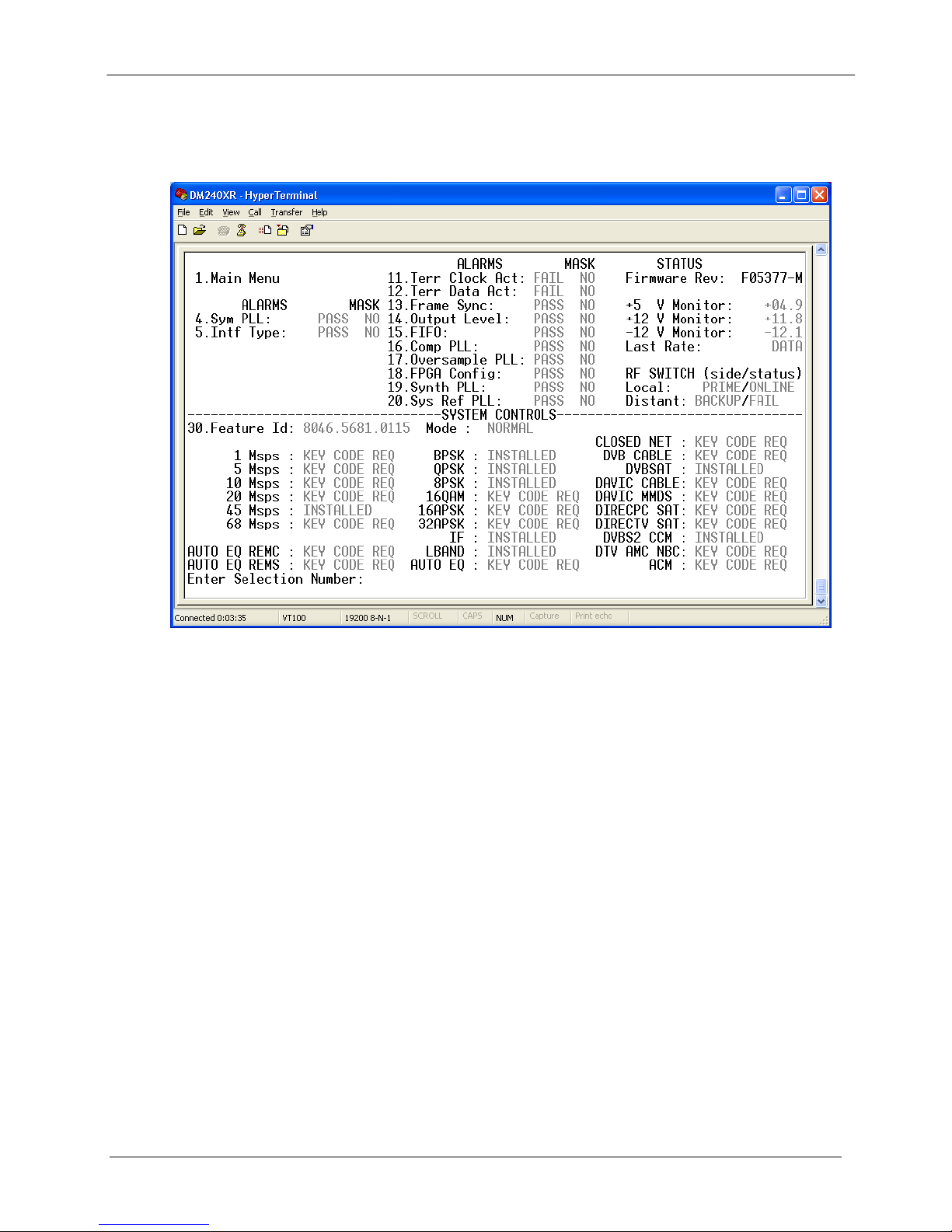
DM240XR High-Speed Digital Modulator User Interfaces
Figure 4-14. SYSTEMS CONTROL Menu
MN-DM240XR– Revision 12 4–47
Page 96

DM240XR High-Speed Digital Modulator User Interfaces
Notes:
MN-DM240XR– Revision 12 4–48
Page 97

Chapter 5. Rear Panel Interfaces
This section discusses the electrical interfaces available from the rear panel. All locations are as
viewed from the rear of the unit unless otherwise specified.
5.1 DM240XR Connections
All DM240XR connections are made to labeled connectors located on the rear of the unit. Any
connection interfacing to the DM240XR must be the appropriate mating connector. DM240XR
Optional Data Interfaces are shown in Fig ures 5-1b – 5-1i.
Figure 5-1a. DM240XR Rear Panel Connectors
Figure 5-1b. DM240XR Rear Panel Connectors (Ethernet)
Figure 5-1c. DM240XR Rear Panel Connectors (ASI IN)
MN-DM240XR– Revision 12 5–1
Page 98

DM240XR High-Speed Digital Modulator Rear Panel Interfaces
Figure 5-1d. DM240XR Rear Panel Connectors (ASI OUT)
Figure 5-1e. DM240XR Rear Panel Connectors (Serial PE CL)
Figure 5-1f. DM240XR Rear Panel Connectors (DVB/M2P RS422 PARA)
Figure 5-1g. DM240XR Rear Panel Connectors (DVB/LVDS PARA)
Figure 5-1h. DM240XR Rear Panel Connectors (HSSI)
Figure 5-1i. DM240XR Rear Panel Connectors (RS530/RS422)
MN-DM240XR– Revision 12 5–2
Page 99

DM240XR High-Speed Digital Modulator Rear Panel Interfaces
5.2 AC Power
The unit is powered from a 100 – 240 VAC, 50 – 60 Hz source. Maximum unit power
consumption is 25 W. The switch turns power on and off to the unit. A chassis ground
connection can be made at the stud locat ed to the lower right of the AC Power Connector.
5.3 Compact Flash Interface (J5)
The Compact Flash Interface allows a Co mpact Flash Card to be inserted for three main
functions:
Normal Operation
Firmware Update
Custom Configuration
5.3.1 Feature Upgrade
Refer to section A.
5.3.2 Firmware Update
A new Compact Flash Card with the upgraded firmware is required for each unit.
1. Power off the unit.
2. Remove Compact Flash.
3. Install new Compact Flash.
4. Power on unit.
5. Verify the firmware under the “SYSTEM MENU”.
5.3.3 Custom Configuration
For a custom configuration, the customer orders a Custom Configuration Compact Flash Card.
Perform the following steps:
1. Power off the unit.
2. Install the Custom Configuration Compact Flash Card.
3. Power the unit on.
The unit will operate in the custom configuration as long as the Compact Flash Card is installed.
If the card is removed and power is cycled, the original operation is restored.
5.4 Ethernet Interface (J6)
The Ethernet Interface (J6) can be used for the monitor & control functions of the unit. The
physical interface is a standard female R J-45 Connector. Refer to Section 4.5 for programming
details.
MN-DM240XR– Revision 12 5–3
Page 100

DM240XR High-Speed Digital Modulator Rear Panel Interfaces
5.5 External Reference (Input)
The External Reference Input (J8) is supplied to allow the customer to phase-lock the modulator’s
internal oscillator to an external reference.
This female BNC Connector accepts a 1.5 – 5 Vp-p @ 50 Ohms. The frequency range of the
external reference is 1 – 10 MHz in 8 kHz steps.
5.6 Remote Port (I/O)
The Remote Port Interface (J4) can be used for the monitor & control functions of the unit. The
physical interface is a female 9-Pin D-Sub Connector. This bi-directional port complies with
RS-485 Electrical Specifications. Refer to Section 7.6 for protocol and programming details.
Pinouts are listed in Table 5-1.
Table 5-1. J4 - RS-485 Remote Control- 9-Pin ‘D’ Female
Pin No. Signal Description Direction
1 Tx (B) Transmit Data (+) Output
5 GND Ground --6 Tx (A) Transmit Data (-) Output
8 Rx (B) Receive Data (+) Input
9 Rx (A) Receive Data (-) Input
5.7 Terminal Port (I/O)
The Terminal Port Interface (J1) can be used for the monitor & control functions of the unit. The
physical interface is a female 9-Pin D-Sub Connector. This bi-directional port complies with
RS-232 Electrical Specifications. Refer to Section 4.8 for terminal interface details. The pinouts
are listed in Table 5-2.
Table 5-2. J1 - RS-232 Terminal Port - 9-Pin ‘D’ Female
Pin No. Signal Name Description Direction
3 TxD Transmit Data Output
2 RxD Receive Data Input
5 GND Ground --7 RTS Request to Send Output
8 CTS Clear to Send Input
MN-DM240XR– Revision 12 5–4
 Loading...