

Page 1

OMS11
Outdoor Modem Switch
Installation and Operation Manual
TM133
Revision 1.1
Comtech EF Data • 2114 W 7th St. • Tempe, AZ 85281 • (480) 333-2200 • Fax: (480) 333-2540 • www.comtechefdata.com
Page 2

OMS11 1:1 Redundancy Switch Warranty Policy
Warranty Policy
WP
Comtech EF Data products are warranted against defects in material and workmanship for a period of two
years from the date of shipment. During the warranty period, Comtech EF Data will, at its option, repair or
replace products that prove to be defective.
For equipment under warranty, the owner is responsible for freight to Comtech E F Data and all related
customs, taxes, tariffs, insurance, etc. Comtech EF Data is responsible for the freight charges only for return
of the equipment from the factory to the ow ner. Comt ech EF Data will return the equipment by the same
method (i.e., Air, Express, Surface) as the equipment was sent to Comtech EF D ata.
All equipment returned for warranty repair must have a valid RMA number issued prior to return and be
marked clearly on the return p ack agin g. Comtech EF Data strongly recommends all equipment be returned
in its original packaging.
Comtech EF Data Corporation’s obligations under this warranty are limited to repair or replacement of failed
parts, and the return shipment to the buyer of the repaired or replaced parts.
Limitations of Warranty
The warranty does not apply to any part of a product that has been installed, altered, repaired, or misused in
any way that, in the opinion of Comtech EF Data Corporation, would affect the reliability or detracts from the
performance of any part of the product, or is damaged as the result of use in a way or with equipment that
had not been previously approved by Comtech EF Data Corporation.
The warranty does not apply to any product or parts thereof where the serial number or the serial number of
any of its parts has been altered, defaced, or removed.
The warranty does not cover damage or loss incurred in transportation of the product.
The warranty does not cover replacement or repair necessitated by loss or damage from any cause beyond
the control of Comtech EF Data Corporation.
The warranty does not cover any labor involved in the removal and or reinstallation of warranted equipment
or parts on site, or any labor required to diagnose the necessity for repair or replacement.
The warranty excludes any responsibility by Comtech EF Data Corpora t io n for incide ntal or con sequent i al
damages arising from the use of the equipment or products, or for any inability to use them either separate
from or in combination with any other equipment or products.
A fixed charge established for each product will be imposed for all equipment returned for warranty repair
where Comtech EF Data Corporation cannot identify the cause of the reported failure.
Exclusive Remedies
Comtech EF Data Corporation’s warranty, as stated is in lieu of all other warranties, expressed, implied, or
statutory, including those of merchantability and fitness for a particular purpose. The buyer shall pass on to
any purchaser, lessee, or other user of Comtech EF Data Corporation’s products, the aforementioned
warranty, and shall indemnify and hold harmless Comtech EF Data Corporation from any claims or liability of
such purchaser, lessee, or user based upon allegations that the buyer, its agents, or employees have made
additional warranties or representations as to product preference or use.
The remedies provided herein are the buyer’s sole and exclusive remedies. Comtech EF Data shall not be
liable for any direct, indirect, special, incidental, or consequential damages, whether based on contract, tort,
or any other legal theory.
TM133 – Rev. 1.1 iii
Page 3

Warranty Policy OMS11 1:1 Redundancy Switch
Warranty Repair Return Procedure
Before a warranty repair can be accomplished, a Repair Authorization must be received. It is at this time
that Comtech EF Data will authorize the product or part to be returned to the Comtech EF Data facility or if
field repair will be accomplished. The Repair Authorization may be requested in writing or by calling:
Comtech EF Data Corporation
2114 W 7
th
Street.
Tempe, Arizona 85281 (USA)
ATTN: Customer Support
Phone: (480) 333-2200
Fax: (480) 333-2540
Any product returned to Comtech EF Data for examination must be sent prepaid via the means of
transportation indicated as acceptable to Comtech EF Data. Return Authorization Number must be clearly
marked on the shipping label. Returned products or parts should be carefully packaged in the original
container, if possible, and unless otherwise indicated, shipped to the above address.
Non-Warranty Repair
When a product is returned for any reason, Customer and its shipping agency shall be responsible for all
damage resulting from improper packing and handling, and for loss in transit, not withstanding any defect or
nonconformity in the product. By returning a product, the owner grants Comtech EF Data permission to
open and disassemble the product as required for evaluation. In all cases, Comtech EF Data has sole
responsibility for determining the cause and nature of failure, and Comtech EF Data’s determination with
regard thereto shall be final.
iv TM133 – Rev. 1.1
Page 4
OMS11 1:1 Redundancy Switch Preface
Preface
P
This manual provides installation and operation information for the Radyne OMS11 1:1
Redundancy Switch. This is a technical document intended for use by engineers, technicians,
and operators responsible for the operation and maintenance of the OMS11.
Conventions
Whenever the information within this manual instructs the operator to press a pushbutton switch
or keypad key on the Front Panel, the pushbutton or key label will be shown in "less than" (<) and
"greater than" (>) brackets. For example, the Reset Alarms Pushbutton will be shown as
<RESET ALARMS>, while a command that calls for the entry of a ‘7’ followed by ‘ENTER’ Key
will be represented as <7,ENTER>.
Cautions and Warnings
A caution icon indicates a hazardous situation that if not avoided, may result in minor or moderate
injury. Caution may also be used to indicate other unsafe practices or risks of property damage.
A warning icon indicates a potentially hazardous situation that if not avoided, could result in death
or serious injury.
TM133 – Rev. 1.1 v
Page 5

Preface OMS11 1:1 Redundancy Switch
Revision
Level
1.0
11-30-07
Initial Release
1.1
2-08-08
Updates. Added Fault Detection
A note icon identifies information for the proper operation of your equipment, including helpful
hints, shortcuts, or important reminders.
Trademarks
Product names mentioned in this manual may be trademarks or registered trademarks of their
respective companies and are hereb y acknowledged.
Copyright
2008, Comtech EF Data This manual is proprietary to Comtech EF Data and is intended for the
exclusive use of Comtech EF Data’s customers. No part of this document may in whole or in
part, be copied, reproduced, distributed, translated or reduced to any electronic or magnetic
storage medium without the express written consent of a duly authorized officer of Comtech EF
Data
Disclaimer
This manual has been thoroughly reviewed for accuracy. All statements, technical information,
and recommendations contained herein and in any guides or related documents are believed
reliable, but the accuracy and completeness thereof are not guaranteed or warranted, and they
are not intended to be, nor should they be understood t o be, represe nt at ions or war ranti es
concerning the products described. Comtech EF Data assumes no responsibility for use of any
circuitry other than the circuitry employed in Comtech EF Data systems and equipment.
Furthermore, since Comtech EF Data is constantly improving its products, reserves the right to
make changes in the specifications of products, or in this manual at any time without notice and
without obligation to notify any person of such changes.
Record of Revisions
Date
Reason for Change
Comments or Suggestions Concerning this Manual
Comments or suggestions regarding the content and design of this manual are appreciated.
To submit comments, please contact the Comtech EF Data Corporation Customer Service
Department.
vi TM133 – Rev. 1.1
Page 6

OMS11 1:1 Redundancy Switch Preface
TM133 – Rev. 1.1 vii
Page 7

Page 8

OMS11 1:1 Redundancy Switch Table of Contents
1
Table of Contents
ToC
Section 1 - Introduction ............................................................................................................. 1-1
1.0 Description ............................................................................................................................. 1-1
1.1 Redundant Power Supplies ................................................................................................... 1-1
1.2 Front Panel Controls .............................................................................................................. 1-2
1.3 Power-Up Defaults ................................................................................................................. 1-2
Section 2 - Theory of Operation ................................................................................................ 2-1
2.0 Theory of Operation ............................................................................................................... 2-1
2.1 OMS11 Operation .................................................................................................................. 2-1
2.1.1 Operating Procedures ........................................................................................................ 2-2
2.1.2 Configuring the OMS11 ...................................................................................................... 2-2
2.1.3 Front Panel Controls ........................................................................................................... 2-2
2.1.4 Manual Mode ...................................................................................................................... 2-2
2.1.5 Auto Mode .......................................................................................................................... 2-2
2.1.6 Power-Up Defaults ............................................................................................................. 2-2
2.2 OMS11 Major Assemblies ..................................................................................................... 2-3
2.2.1 Main Switch Board .............................................................................................................. 2-3
2.2.2 Front Panel ......................................................................................................................... 2-3
2.2.3 Redundant Power Supplies ................................................................................................ 2-3
2.3 OMS11 General Operation .................................................................................................... 2-3
2.3.1 Signals ................................................................................................................................ 2-3
2.3.2 Backup ................................................................................................................................ 2-3
2.3.3 Fail-Safe ............................................................................................................................. 2-3
2.3.4 OMS11 Fault Relays .......................................................................................................... 2-4
2.4 Fault Detection ...................................................................................................................... 2-4
Section 3 - User Interfaces ........................................................................................................ 3-1
3.0 User Interfaces ...................................................................................................................... 3-1
3.1 Front Panel Interface ............................................................................................................. 3-1
TM133 – Rev. 1.1
Page 9

Introduction OMS11 1:1 Redundancy Switch
2
Section 4 - Installation ............................................................................................................... 4-1
4.0 Installation Requirements ...................................................................................................... 4-1
4.1 Unpacking .............................................................................................................................. 4-1
4.1.1 Test Data Sheet .................................................................................................................. 4-2
4.2 Site Considerations ............................................................................................................... 4-2
4.2.1 Power Sources ................................................................................................................... 4-2
4.3 System Setup & Connections ................................................................................................ 4-3
Section 5 - Connector Pinouts .................................................................................................. 5-1
5.0 OMS11 External Interface Connections ................................................................................ 5-1
5.1 LED Indicators ....................................................................................................................... 5-2
5.2 Power Input............................................................................................................................ 5-2
5.2.2 AC Power Input (J 6, J 10) ................................................................................................... 5-2
5.2.3 DC Power Input (J6, J10) (Optional) .................................................................................. 5-2
5.3 Ground Lug ............................................................................................................................ 5-3
5.4 Remote Monitor & Control (J8) .............................................................................................. 5-3
5.4.1 Terminal Mode (RS232) ..................................................................................................... 5-3
5.4.2 Modem Remote Communications (RLLP/RS485).............................................................. 5-4
5.4.3 Common Equipment Faults (J8) ......................................................................................... 5-4
5.4.3.1 Fault Detection ................................................................................................................ 5-5
5.5 Terrestrial Data Interface (J7) - RS422 Sync, Async Overhead, G.703 Balanced I/O Port .. 5-7
5.6 Modem A Data Interface (J1) - RS422 Sync, Async Overhead, G.703 Balanced I/O Port ... 5-9
5.7 Modem B Data Interface (J13) - RS422 Sync,Async Overhead,G.703 Balanced I/O Port . 5-11
5.8 Modem A Remote/Terminal/Fault Port on OMS11 (J2) ...................................................... 5-13
5.9 Modem A Remote/Terminal/Fault Port on OMS11 (J14) .................................................... 5-14
5.10 TX &RX Waveguide Switch Interface (J5 & J9) ................................................................ 5-14
5.11 Mating Connectors ............................................................................................................ 5-16
Section 6 - Maintenance and Troubleshooting ........................................................................ 6-1
6.0 Basic Troubleshootin g and Mai nte nanc e .............................................................................. 6-1
6.1 Basic User Checks ................................................................................................................ 6-1
6.1.1 Checking the Cabling and Connectors ............................................................................... 6-1
6.2 Major and Minor Faults .......................................................................................................... 6-1
TM133 – Rev. 1.1
Page 10

OMS11 1:1 Redundancy Switch Table of Contents
3
Section 7 - Technical Specifications ........................................................................................ 7-1
7.0 Introduction ............................................................................................................................ 7-1
7.1 General .................................................................................................................................. 7-1
7.2 Monitor and Control ............................................................................................................... 7-1
7.3 Terrestrial Interfaces .............................................................................................................. 7-1
7.4 Modem Data Cables .............................................................................................................. 7-1
7.5 Front Panel LED Indicators ................................................................................................... 7-1
7.6 Front Panel Controls .............................................................................................................. 7-2
7.7 Power and Environmental ..................................................................................................... 7-2
7.8 Physical ................................................................................................................................. 7-2
Appendix A - OMS11 DIP Switch Configuration ...................................................................... A-1
Appendix B - OMS11 Remote Comunications ......................................................................... B-1
B.0 Host Computer Remote Communications ............................................................................ B-1
B.0.1 Protocol Structure .............................................................................................................. B-1
B.0.2 Protocol Wrapper ............................................................................................................... B-1
B.0.3 Frame Description and Bus Handshaking ......................................................................... B-3
B.0.4 Global Response Operational Codes ................................................................................. B-5
B.0.5 Software Compatibility ....................................................................................................... B-5
B.0.6 RLLP Summary .................................................................................................................. B-6
B.1 Remote Port Packet Structure .............................................................................................. B-6
Appendix C - Interconnecting Cable Drawings ....................................................................... C-1
Glossary ..................................................................................................................................... G-1
TM133 – Rev. 1.1
Page 11

Introduction OMS11 1:1 Redundancy Switch
4
TM133 – Rev. 1.1
Page 12

OMS11 1:1 Redundancy Switch Introduction
1-1
Introduction
1
1.0 Description
The Radyne OMS11 Outdoor Modem Switch provides redundancy protection for the OM20
Outdoor Modem, BUC and LNB. The OMS11 offers redundancy support for OM20 user data,
Asynchronous data, RS485 and BUC/LNB Waveguide Switching control. The OMS11
redundancy system is based on a Chain switching system that switches the IF/RF primary path to
the IF/RF Backup path. Optional BUCs, LNBs, Waveguide Switches and Mounting hardware are
optional items that can be supplied with the system. Contact Radyne for supported hardware
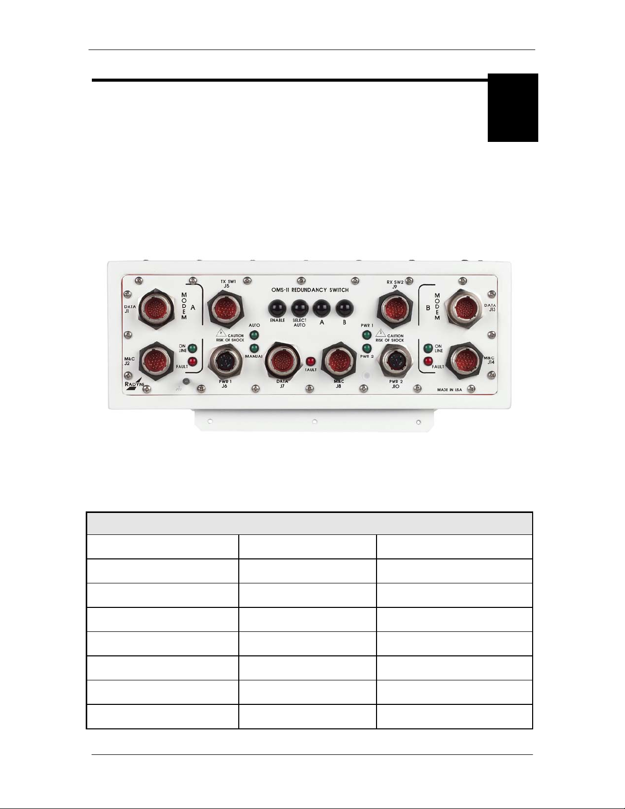
options. Refer to Figure 1-1 for an illustration of the OMS11 1:1 Redundancy Switch Front Panel
and Figure 1-3 of an OMS11 Functional Block Diagram.
Operating in the Automatic Mode, the OMS11 immediately places a Backup Modem and IF/RF
Path online in the event of a Primary Modem/IF/RF path fails. The OMS11 chain switches the
modem, BUC and LNB. In the Manual Mode, the user may designate the selected Online
Primary Modem from either the Interactive Front Panel or a remote Terminal Interface. The
backup functions of the OMS11 may be performed manually via the front panel or the RS485,
RLLP remote protocol or the RS232 Terminal port.
Figure 1-1 OMS11 1:1 Redundancy Switch Front Panel
1.1 Redundant Power Supplies
The OMS11 is equipped with two fully redundant internal power supplies. Each power supply is
independent of the other, including their source of AC or DC input source. The OMS11 remains
fully operational as long as either power supply is providing a source of power. The power
supplies are internal to the OMS11 Chassis.
TM133 – Rev. 1.1
Page 13

Introduction OMS11 1:1 Redundancy Switch
1-2
1.2 Front Panel Controls
The Front Panel of the OMS11 provides all of the necessary controls and LED indicators to
provide the operator with online status and backup status of the online and backup OM20
Modems.
1.3 Power-Up Defaults
During power-up, the OMS11 initializes itself to the last mode set by the Front Panel
Pushbuttons.
TM133 – Rev. 1.1
Page 14

OMS11 1:1 Redundancy Switch Introduction
1-3
TM133 – Rev. 1.1
Page 15

Page 16
OMS11 1:1 Redundancy Switch Theory of Operation
2-1
Theory of Operation
2
2.0 Theory of Operation
The Radyne OMS11 Outdoor Modem Switch provides redundancy protection for the OM20
Outdoor Modem, BUC and LNB. The OMS11 redundancy system is based on a Chain switching
system that switches the IF/RF primary path to the IF/RF Backup path. The Chain Switching
system can includes BUCs, LNBs, Waveguide, Waveguides Switches, mounting hardware and
connecting cables. BUCs, LNBs, Waveguide Switches and Mounting hardware are optional
items that can be supplied with the system. Refer to Figure 1-1 for an illustration of the OMS11
1:1 Redundancy Switch Front Panel and Figure 2-1 for the OMS11 Functional Block Diagram.
The BUC and LNB switch over fault detection system is primarily done by the OM20 Modem.
When the OM20 is configured to supply power to the BUC and LNB, the modem uses internal
detection circuitry to monitor current and voltage status of the BUC and LNB. User must properly
set up the BUC/LNB voltage and current threshold limits on the OM20. Refer to the OM20 user
manual for proper set.
In cases where the BUCs are powered by an external power supply, fault detection can be
detected by the OM20 only if the BUC includes Normally Closed contact closures. In order to
support BUC redundancy, the BUC must have Normally Closed Contact closures available for the
OMS11/OM20 to support redundancy.
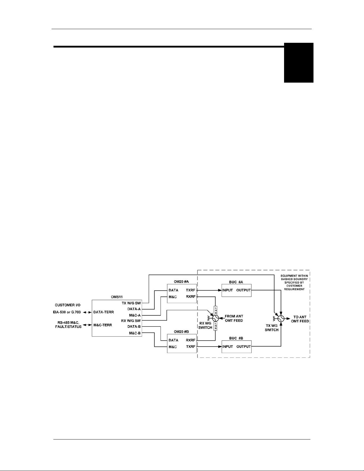
2.1 OMS11 Operation
A block diagram of the signal flow is shown in Figure 2-1 below.
Figure 2-1 Functional Block Diagram
TM133 – Rev. 1.1
Page 17

Theory of Operation OMS11 1:1 Redundancy Switch
2-2
2.1.1 Operating Procedures
The OMS11 is designed to require minimal operator intervention and control during normal
operation. After initial setup, the unit should operate in a relatively ‘transparent’ manner,
providing trouble-free backup of the online Modems. The scope of this section is limited to
instruction on the various modes of control available to the operator. Refer to Section 3-1 for the
OMS11 Front Panel Controls and Indicators and Table 2-1 for a description of the Controls and
Indicators.
2.1.2 Configuring the OMS11
The redundancy switch must be properly configured prior to operation. Date interface type,
Remote communication type and remote baud rate must be set correctly to meet the users
needs. Configuring these options can only be done by removing the cover and accessing the dip
switches on the board. Appendix A of this manual gives specific information about the dip switch
settings for configuring the Terminal and Remote ports. If you need assistance with the settings,
contact Radyne customer service department.
2.1.3 Front Panel Controls (Refer to Figure 2-1)
The purpose of the ‘ENABLE’ pushbutton on the front panel is to reduce the risk of accidentally
changing the operating modes of the OMS11 by accidentally bumping any one of the front panel
pushbuttons. For any one of the front panel pushbuttons to function, the ‘ENABLE’ pushbutton
must be depressed simultaneously with the desired function pushbutton. Depress the ‘ENABLE’
pushbutton. This pushbutton must be depressed to allow the operator to proceed with any other
configurations. The ‘MANUAL’ LED should illuminate and the FAULT indicator may momentarily
flash. Under the MOD region of the front panel, depress ‘SELECT A’ to bring Modem ‘A’
modulator online. The green LED should illuminate. Under the DEMOD region of the front panel,
depress ‘SELECT A’ to bring modem ‘A’ demodulator online. The Green LED should illuminate.
The OMS11 should now be in backup mode with modem ‘A’ online.
2.1.4 Manual Mode
To manually select which Modem is to be placed online, simultaneously depress the ‘ENABLE’
pushbutton and the appropriate Modem ‘SELECT’ pushbutton. When a Modem select ion is
made, the OMS11 enters Manual Mode to carry out the selection, and will not respond to either
modem’s Modem Fault signals until placed back into Auto Mode.
2.1.5 Auto Mode
To enable automatic backup in the event of a Modem failure, the OMS11 must be placed into the
Auto Mode. First, select which Modem that will be active by following the ‘Manual Mode’
procedure in the previous paragrap h. To enter the Auto Mode, simultaneously depress the
‘ENABLE’ pushbutton and the ‘SELECT AUTO’ pushbutton. The OMS11 will then enter into Auto
Mode with the last selections made in Manual Mode. In the Auto Mode, the decision to switch
from one Modem to another is made automatically by monitoring the Fault signals from each
modem.
2.1.6 Power-Up Defaults
During power-Up, the OMS11 initiali ze s its elf to the last mode set by the operator on the front
panel pushbuttons.
TM133 – Rev. 1.1
Page 18

OMS11 1:1 Redundancy Switch Theory of Operation
2-3
2.2 OMS11 Major Assemblies
The OMS11 Redundancy Control Unit contains the modules that control and monitor the
operation of the 1:1 Switch system. The 1:1 Switch is composed of the followin g major
assemblies and components:
Main Switch Board
Waveguide Switch Board
Front Panel
Dual (Redundant) Po wer Supplies
2.2.1 Main Switch Board
The Main Switch Board contains the OMS11 1:1 Switch Intelligenc e and Memory Circuitry and all
switching circuitry. The microprocessor controls and coordinates all of the major functions of the
Switch and performs all necessary calculations. The non-volatile system memory on the board
stores the switching parameter settings for each modem channel. Control and data signals are
routed to the appropriate devices in the system through various latches and transceivers that are
controlled by the microprocessor.
2.2.2 Front Panel
The Front Panel contains the LED Indicators and the pushbutton switches needed to control and
operate the OMS11. Refer to Figure 3.0 for a description of Front Panel Indicators.
2.2.3 Redundant Power Supplies
The 1:1 Switch comes equipped with two fully redundant internal power supplies (PS1 and PS2)
that supplies power to the switch and external switching components. Each supply is fully
independent of the other, including their source of AC/DC power and fusing. The Switch can
remain fully operational as long as it is supplied with a source of voltage from either power
supply.
2.3 OMS11 General Operation
2.3.1 Data Signals
Modem data signals are backed-up through a passive switching system. Signals that are
required to maintain the modem in off-line (hot-standby) are buffered by appropriate circuitry to
minimize loading on incoming signals.
2.3.2 Backup
If an online Modem fault is sensed, and the off-line Modem is in a non-faulted state, the OMS11
will switch to the Modem without the fault. The Fault Signal has a small debounce delay to
prevent false triggering. If the faulted Modem has its fault cleared, it stays off-line unless the
other MODEM has subsequently faulted.
2.3.3 Fail-Safe
If the OMS11 has a non-recoverable internal fault, the swit c h w il l revert back to Modem A, the
Switch Fault LED is illuminated, and the Switch Fault Relay switches to a faulted state.
TM133 – Rev. 1.1
Page 19

Theory of Operation OMS11 1:1 Redundancy Switch
2-4
If Power Supply 1 and Power Supply 2 simultaneously fail, the switching circuitry in the OMS11
reverts back to Modem A, and the Switch Fault Relay switches to a faulted state. Modem B does
not receive buffered signals in this condition.
2.3.4 OMS11 Fault Relays
The OMS11 M&C Connector (J8) has Form-C contacts available that indicate modem online and
OMS11 Fault status. Refer to section for additional information.
2.4 Fault Detection
The OMS11 & OM20 work simultaneously to determine the status of all the componen ts within
this system. The OMS11 & OM20 are capable of monitoring BUC and LNB redundancy system.
Faults detection is established by the OM20 and forwarded to the OMS11. Fault detection for a
redundant BUC system will be different based on whether the BUC Power is supplied by the
OM20 or if the BUC Power is supplied by an external power source. If the BUC power is supplied
externally, then the BUC must have Normally Closed Form C Fault contacts so the OMS11/OM20
can monitor the BUC fault status.
Fault detection with the OM20 supplying power to BUC:
• BUC Faults - OM20 uses internal fault detection circuitry to determine BUC status and
initiates a fault that is forwarded to the OMS11
• OM20 uses internal fault detection circuitry to determine LNB status and initiate fault
Fault detection with BUC power supplied externally:
• BUC must have Normally Closed Form C contacts in order for BUC fault detection to
work
• OM20 data cable CAR5902 or CAR5918 has an external connector that is used to
connect and monitor Form C Contacts from the BUC.
• OM20 uses internal fault detection circuitry to determine LNB status and initiate fault
TM133 – Rev. 1.1
Page 20

OMS11 1:1 Redundancy Switch Theory of Operation
2-5
TM133 – Rev. 1.1
Page 21

Page 22
OMS11 1:1 Redundancy Switch User Interfaces
3-1
applied
Power Available
Power 2
Indicates PS2 has power
applied
LED illuminates Green for
Power Available
Fault
Indicates a Switch Fault
has occurred
LED illuminates Red for Switch
Fault
Auto (LED)
Indicates OMS11 is in the
Auto Mode
LED illuminates Green for Auto
Mode
the Manual Mode
Manual Mode
SELECT AUTO (Pushbutton)
-------------------
Allows the operator to select
Automatic Mode of operation
ENABLE (Pushbutton)
-------------------
Enables Front Panel controls to
function
User Interfaces
3
3.0 User Interfaces
These are:
Front Panel Interface – Refer to Section 3.1.
Remote Interface – Refer to Appendix B.
Figure 3-1 OMS11 Front Panel
3.1 Front Panel Interface
Table 3-1. OMS11 Front Panel Controls and Indicators
Nomenclature Description Function
Power 1 Indicates PS1 has power
Manual (LED) Indicates the OMS11 is in
LED illuminates Green for
LED illuminates Green for
TM133 – Rev. 1.1
Page 23

User Interfaces OMS11 1:1 Redundancy Switch
3-2
SELECT Modem A
--------------------
Allows the operator to select
SELECT Modem B
--------------------
Allows the operator to select
Online LED
Indicates Modem A is
LED illuminates Green for Online
Fault LED
The OMS11 has received
LED illuminates Red for Fault
Online LED
Indicates Modem B is
LED illuminates Green for Online
Fault LED
The OMS11 has received
LED illuminates Red for Fault
(Pushbutton)
(Pushbutton)
Modem A
Modem B
Modem A Controls and Indicators
online
a fault from Modem A
Modem B Controls and Indicators
online
a fault from Modem B
TM133 – Rev. 1.1
Page 24

OMS11 1:1 Redundancy Switch User Interfaces
3-3
TM133 – Rev. 1.1
Page 25

Page 26
OMS11 1:1 Redundancy Switch Installation
4-1
Installation
4
4.0 Installation Requirements
The diagrams in this section display the OMS11 and OM20s mounted on the Antenna King Post
as shown in figure 4-1 an d 4-2. The cables supplied in the base system are based on this layout
utilizing the mounting kit supplied by Radyne.
There are no user-serviceable parts located inside the OMS11 Chassis.
There is a potential shock haz ard internally at the power supply module.
DO NOT open the OMS11 Chassis under any circumstance s.
Before initially applying power to the unit, it is a good idea to disconnect
the transmit output from the operating ground station equipment. This is
especially true if the curr ent OMS11 configuration settings are unknown,
where incorrect setting could disrupt existing communications traffic.
The OMS11 is shipped with protective covers over the connectors. The
protective covers are used to create a moisture tight seal. Protective
covers must remain on the unit if connector is not used.
4.1 Unpacking
The OMS11 was carefully packaged to avoid damage and should arrive complete with the
following items for proper installation:
TM133 – Rev. 1.1
Page 27

Installation OMS11 1:1 Redundancy Switch
4-2
OMS11 1:1 Redundancy Switch Unit
Two AC or DC Mating connectors (J6 & J10)
Data Mating Connector (J7)
M&C Mating Connector (J8)
OMS11/OM20 Interconnect Cables and Materials as required
1:1 Switch System Test Data Sheet
An Installation and Operation Manual
C-Band or Ku Band Waveguide Switches (Optional)
Antenna Mounting hardware (Optional)
BUCS and LNBS (Optional)
4.1.1 Test Data Sheet
Each OMS11 1:1 Redundancy Switch system is shipped with a Test Data Sheet. This report
contains information on the results of the Switch quality control testing. The report also includes
information pertaining to the system settings that were made at the factory. Radyne recommends
that the user save this report for future reference.
4.2 Site Considerations
Adequate site planning and preparation simplifies the installation process and results in a more
reliable system. The user should ensure that the site has adequate electrical power,
environmental controls and protection against sources of electrical radiation and interference.
4.2.1 Power Sources
The power sources should be properly grounded and as free as possible from electrical
interference. The OMS11 employs a dual redundant power supply configuration. Each power
connection on the OMS11 must be plugged into its own separate power circuit. Each circuit must
have its own independent circuit breaker.
Grounding is achieved automatically when the properly terminated power connector is inserted
into the power receptacle. This should be checked by testing that there is no voltage present
between the chassis of the Switch and the power line ground.
The protective ground must not be bypassed or defeated In any way.
Defeating the ground may result in operator Injury or damage to the
system.
TM133 – Rev. 1.1
Page 28

OMS11 1:1 Redundancy Switch Installation
4-3
PROPER GROUNDING PROTECTION: During installation and setup, the
user must ensure that the unit is properly grounded. The equipment
shall be connected to the protective earth connection through the end
use protective earth protection.
4.3 System Setup & Connections
1. Install OMS11/OM20 Mounting kit as shown in Figure 4-1 and Table 4-1. This displays
the optional Radyne unistrut mounting kit for antenna kingpost mounting.
2. Mount the units as shown per figure 4-2 below. Configure units.
Note: Customer configurations may vary.
3. Install BUCs, LNBs and waveguide hardware onto mounting kit as shown in Figure 4-4.
This displays the optional Radyne unistrut mounting kit for antenna kingpost mounting.
4. Attach the Power Cords to the OMS11 and OM20 units to be connected.
5. Power up the units to be connected. Their Green Power LEDs should illuminate.
If not, refer to the appropriate Installation and Operation manual for further action to be
taken.
TM133 – Rev. 1.1
Page 29

Installation OMS11 1:1 Redundancy Switch
4-4
1
FP5914-2
UNISTRUT 2 FEET
3
ZB356
PIPE BLOCK ELECTRO-PLATED FINISH
4
Z15ATC-04403
ALL THRD ROD 7/16-14 18.8 SS 3FT
5
Z15FNC3-044
NUT, 7/16-14, 18.8 S/S HEX
6
Z15LW3-044
LOCK WASHR 7/16 18.8 SS MEDIUM SPLT
7
Z15LW3-044
WASHER, 7/16, 18.8 S/S FLAT
8
Z15LW3-038
WASHER SPLIT LOCK 3/8 SS
9
Z15LW3-038
WASHER 3/8IN SS FLAT
10
Z15CSC3-0380125
BOLT HEXHD 3/8X1-1/4IN SS
11
ZN228WO
CHANNEL NUT 3/8-16 ELEC PLATE ZINC
Figure 4-1 Antenna Mounting Kit
Item Radyne P/N Description
2 FP/5914-4 UNISTRUT 4 FEET
Table 4-1 Antenna Mounting Kit
TM133 – Rev. 1.1
Page 30

OMS11 1:1 Redundancy Switch Installation
4-5
TM133 – Rev. 1.1
Figure 4-2 Antenna Mount Front View on King Post
NOTE: All connections are facing down
Page 31

Installation OMS11 1:1 Redundancy Switch
4-6
CAR5902
J13
--
J3
--
--
CAR5918**
J13
--
J3
--
--
CAR5903
J14
--
J2
--
--
CAR5904
J9
--
--
--
J
J
CAR5933
J3 Plug
Figure 4-3 Antenna Mount Bottom View
Cable
Connects
CAR5902* J1 J3 -- -- --
CAR5918** J1 J3 -- -- --
CAR5903 J2 J2 -- -- --
CAR5904 J5 -- -- J --
CAR5933 J3 Plug
* CAR5902 is for G703 Balanced Communications
** CAR5918 is for RS422 Serial Communications
OMS11
Location
Table 4-3 Cable Connections between OM20 and OMS11
Modem A
Location
Modem B
Location
TX
Waveguide
RX
Waveguide
BUC
A/B
J
TM133 – Rev. 1.1
Page 32

OMS11 1:1 Redundancy Switch Installation
4-7
Figure 4-4 BUC Mount Front View on King Post
NOTE: Reference only
TM133 – Rev. 1.1
Page 33

Installation OMS11 1:1 Redundancy Switch
4-8
TM133 – Rev. 1.1
Page 34

OMS11 1:1 Redundancy Switch Connector Pinouts
5-1
J1
DATA A
RS422 Data I/O / G.703 Balanced / Async
MODEM A
J2
M&C A
RS485 Monitor & Control
MODEM A
J6
PWR 1
Power
OMS11
J7
DATA
RS422 Data I/O / G.703 Balanced / Async
OMS11
J8
M&C
RS232/RS485 Monitor & Control
OMS11
J9
RX SW2
RX Waveguide I/O, 48V
OMS11
J10
PWR 2
Power
OMS11
J13
DATA B
RS422 Data I/O / G.703 Balanced / Async
MODEM B
J14
M&C B
RS485 Monitor & Control
MODEM B
Connector Pinouts
5
5.0 OMS11 External Interface Connections
All OMS11 external connections are interconnected to labeled connectors located on the front of
the unit. Any connection interfacing to the OMS11 must utilize the appropriate mating connector
(supplied). Refer to Table 5-1. OMS11 Connections and Figure 5-1. OMS11 Connection Ports
for the standard unit. Reference throughout this section will be identified as the OMS11.
Table 5-1. OMS11 Connections
Connector Label Description Location
J5 TX SW1 TX Waveguide I/O, 48V OMS11
Figure 5-1. OMS11 Connection Ports
TM133 – Rev. 1.1
Page 35

Connector Pinouts OMS11 1:1 Redundancy Switch
5-2
FAULT
Modem has a fault
MODEM A
AUTO
Auto Mode selected
OMS11
MANUAL
Manual Mode selected
OMS11
FAULT
OMS 11 has a fault
OMS11
PWR 1
Power 1 status
OMS11
PWR 2
Power 2 status
OMS11
ONLINE
Modem online
MODEM B
FAULT
Modem has a fault
MODEM B
5.1 LED Indicators
There are nine (9) Light Emitting Diodes (LED’S) on the front of the unit. LEDs identify status of
Modem A, Modem B and OMS11. LEDs for Modem A and Modem B include Modems Online
Status and Fault Status. LEDs for the OMS11 include Power 1 Status, Power 2 Status, OMS11
Fault status, Auto Mode and Manual Mode. When power is supplied to the unit and the power
supply is functioning normally, this LED will be Green. Refer to Table 5-2. LED’s for pin-out
descriptions.
Table 5-2. LED’s
Label Description Location
ONLINE Modem online MODEM A
5.2 Power Input
5.2.1 AC Power Input (J6, J10)
AC Inputs are located on connector J6 and J10 of the OMS11. The auto-ranging univer sa l power
supply input allows for the connection of AC power to the port between the range of 100 – 240
VAC and 50 – 60 Hz. Power consumption for the unit is 1.0A (OMS11) only. An external chassis
ground post is located on the OMS11. The ground post is a #10-32 threaded stud that is used for
external grounding and should not be used to ground the AC power Source on J6 and J10. The
mating power connector is a 4-pin socket MFG P/N (D38999/24FC4SN) connecter. The mating
connector supplied with the unit.
Refer to Table 5-3 AC Po w erfor the connector pinouts.
Table 5-3 AC Pow er
A Line (L1)
B Neutral (L2)
C Ground
5.2.2 DC Power Input (J6, J10) (Optional)
An Optional DC Power Input is available for the OMS11. DC Inputs are located on connector J6
AND J10 of the OMS11. The unit may be powered from a 44 – 56 VDC sour c e with maximum
power consumption is 1.5 amps. This port is a 4-pin plug MFG P/N (D38999/24FC4PN)
connector. The mating connector supplied with the unit. Refer to Table 5-4. DC Power for the
connector pinouts.
TM133 – Rev. 1.1
Page 36

OMS11 1:1 Redundancy Switch Connector Pinouts
5-3
Table 5-4. DC Power
A – VDC
B + VDC
C Ground
D N/C
5.3 Ground Lug
An external chassis ground post is located on the OMS11, which requires a #10-32 threaded
stud.
PROPER GROUNDING PROTECTION: During installation and setup, the
user must ensure that the unit is properly grounded. The equipment shall
be connected to the protective earth connection through the end use
protective earth protection.
5.4 Remote Monitor & Control (J8)
This port functions as the OMS11 Remote and Fault port utilizing an 18-Pin D38999/24FD18PN
Connector. The Remote Port located on J8 allows for control and monitoring of parameters and
functions via an RS-232 Serial Interface or RS-485 for RLLP Protocol. ‘Equipment remote setup
parameters can be configured via the main board or Terminal mode. Based on the user's
application, this may require the user to set the Remote Port, properly configuring the units for
Multidrop Address followed by setting the Remote Interface from RS232 to RS485.
The mating connector is supplied with the unit. Refer to Table 5-5 for the Remote/Terminal
connector pinouts.
The OMS11’s internal M&C system is connected to most of the circuitry on any board contained
in the chassis. These connections provide status on the condition of the circuitry and provide the
data required for the various measurements the OMS11 provides. The on-board M&C proc ess es
this information and generates status indications and alarms when necessary. Status information
is available via the Remote port and the Form-C fault connections available on this connector.
This summary information can be connected to external equipment or alarms. Refer to Table 5-3.
5.4.1 Terminal Mode (RS232)
The Terminal Mode has the advantage of providing full screen access to the switches
parameters, but requires a separate terminal or computer running a Terminal Program. No
external software is required other than VT-100 Terminal Emulation Sof tware (e.g. “Procomm”
for a computer when used as a terminal. The Control Port is normally used as an RS–232
TM133 – Rev. 1.1
Page 37

Connector Pinouts OMS11 1:1 Redundancy Switch
5-4
Connection to the terminal device. This is the standard configuration when shipped from factory.
Refer to Table 5-5for pinouts. Refer to Appendix A for configuring unit to RS232 Terminal.
The factory terminal setup is as follows:
Emulation Type: VT-100 (can be changed)
Baud Rate: 9600
Data Bits: 8
Parity: No Parity (Fixed)
Stop Bits: 1 Stop Bit
The factory terminal Baud Rate can be changed by accessing dip switches located on the main
board. Internal DIP switches are accessible only by removing the top cover. Refer to Appendix
A, Figure A2.
5.4.2 Modem Remote Communications (RLLP/RS485)
The RLLP Remote Port is located on J8 allows for control and monitoring of parameters and
functions via an RS-485. Control and status messages are conveyed between the modem and all
subsidiary modems and the host computer using packetized message blocks in accordance with
a proprietary communications specification. This communication is handled by the Radyne Link
Level Protocol (RLLP), which serves as a protocol ‘wrapper’ for the RM&C data. Complete
information on monitor and control software is contained in the following sections. Refer to Table
5-5 for pinout descriptions. Refer to Appendix A for configuring the unit to RS485 Remote.
Refer to Appendix B for the RLLP Protocol.
This requires the user to first properly setup the unit ensuring Multidrop Address are configured
as needed. The OMS11 has internal DIP switches that are accessible only by removing the top
cover. DIP switch S3 is used to configure remote baud rates and addressing. Refer to Appendix
A, Figure A2 for dip switch information. If you are having trouble with DIP switch settings, contact
Radyne Customer Service for any additional help.
5.4.3 Common Equipment Faults (J8)
Common equipment fault hardware is available on the OMS11. The OMS11 M&C Connector (J8)
has Form-C contacts available that indicate which modem is online and indicates OMS11 Fault
status. Refer to Table 5-5.
Table 5.5. Remote Monitor & Control / Faults (J8)
Pin No. Signal Name Signal Direction
A Receive Data RS-232 RXD-232 Input
B Transmit Data RS-232 TXD-232 Output
C Reserved --- --D Transmit Data RS-485 (+) TX-485-B Output
E Transmit Data RS-485 (-) TX-485-A Output
F Receive Data RS-485 (+) RX-485-B Input
G Receive Data RS-485 (-) RX-485-A Input
TM133 – Rev. 1.1
Page 38

OMS11 1:1 Redundancy Switch Connector Pinouts
5-5
H Ground GND ---
J Switch Fault – C SF-C --K Switch Fault – NC SF-NC --L Switch Fault – NO SF-NO ---
M No Connect --- --N No Connect --- ---
S DSR ---
R No Connect --- --U No Connect --- ---
P Modem A Online Relay – NC MO-NC --T Modem B Online Relay – NO MO-NO ---
5.4.3.1 Fault Detection
The OMS11 & OM20 work simultaneously to determine the status of all the components within
this system. The OMS11 & OM20 are capable of monitoring BUC and LNB redundancy system.
Faults detection is established by the OM20 and forwarded to the OMS11. Fault detection for a
redundant BUC system will be different based on whether the BUC Power is supplied by the
OM20 or if the BUC Power is supplied by an external power source. If the BUC power is supplied
externally, then the BUC must have Normally Closed Form C Fault contacts so the OMS11/OM20
can monitor the BUC fault status.
Figure 5-2 reflects the BUC fault detection connector which is required for BUC that are using
external Power supplies.
Figure 5-2 External BUC fault detection o n CAR5902 or CAR5918
TM133 – Rev. 1.1
Page 39

Connector Pinouts OMS11 1:1 Redundancy Switch
5-6
Fault detection with the OM20 supplying power to BUC:
• BUC Faults - OM20 uses internal fault detection circuitry to determine BUC status and
initiates a fault that is forwarded to the OMS11
• OM20 uses internal fault detection circuitry to determine LNB status and initiate fault
Fault detection with BUC power supplied externally:
• BUC must have Form C contacts in order for BUC fault detection to work
• OM20 data cable CAR5902 or CAR5918 has an external connector that is used to
connect and monitor Form C Contacts from the BUC.
• OM20 uses internal fault detection circuitry to determine LNB status and initiate fault
TM133 – Rev. 1.1
Page 40

OMS11 1:1 Redundancy Switch Connector Pinouts
5-7
5.5 Terrestrial Data Interface (J7) – RS422 S ynchronous Data,
Asynchronous Overhead Data, and G.703 Balanced Data I/O Port
This 37 Pin D38999/24FD35PN Connector contains the RS422 data connections, the RS485
Asynchronous Overhead data interface and the G.703 Balanced interface.
Refer to Table 5-6 for pin-outs. Refer to Table 5-7 for G.703 Balanced pin-outs.
Table 5.6. RS422 Synchronous Data I/O; Async Data Connector (J7)
J7
Pin No.
1 Shield--- --- 1
2 Send Data B (+) SD-B Input 14
3 Send Data A (-) SD-A Input 2
4 Send Timing A (-) ST-A Output 15
5 Receive Data RD-A Output 3
6 Receive Data B (+) RD-B Output 16
7 Request To Send A (-) RS-A Input 4
8 Receive Timing A (-) RT-A Output 17
9 Clear To Send A (-) CS-A Output 5
10
11 Data Mode A (-) DM-A Output 6
12 Request To Send B (+) RS-B Input 19
13 Signal Ground SGND --- 7
14 Data Terminal Ready A (-) TR-A Input 20
Signal Name Signal Direction EIA-530 25
Pin Connector
Reference
15 Receiver Ready A (-) RR-A Output 8
16
17 Receive Timing B (+) RT-B Output 9
18 Data Mode B (+) DM-B Output 22
19 Receiver Ready B (+) RR-B Output 10
20 Data Terminal Ready B (+) TR-B Input 23
21 Terminal Timing B (+) TT-B Input 11
22 Terminal Timing TT-A Input 14
23 Send Timing B (+) ST-B Output 12
24 No Connect --- --- 25
25 Clear To Send B (+) CS-B Output 13
TM133 – Rev. 1.1
Page 41

Connector Pinouts OMS11 1:1 Redundancy Switch
5-8
Table 5.6 cont. RS422 Synchronous Data I/O; Async Data Connector (J7)
J7
Async - Signal Name Signal Direction
Pin No.
26 Transmit Data B (Async) TXD_B Input N/C
27 Transmit Data A (Async) TXD_A Input N/C
30 Receive Data A (Async) RXD_A Output N/C
31 Receive Data B (Async) RXD_B Output N/C
Table 5.7. G.703 Balanced (J7)
J7
G703 Balance - Signal Name Signal Direction G.703
Pin No.
32 Send Data (-) SD-A Input 1
35 Receive Data A (-) RD-A Output 3
34 Ground GND --- 4
33 Send Data (+) SD-B Input 9
36 Receive Data B (+) RD-B Output 11
37
Balanced
15 Pin
Connector
Reference
29
28
TM133 – Rev. 1.1
Page 42

OMS11 1:1 Redundancy Switch Connector Pinouts
5-9
5.6 Modem A Data Interface (J1) – RS422 Synchronous Data,
Asynchronous Overhead Data, and G.703 Balanced Data I/O Port
This 37Pin D38999/24FD35PN Connector contains the RS422 data connections, RS485
Asynchronous Overhead data interface; G .7 03 Ba lanced interface, and the Open Collector
Modulator and Demodulator Faults. Refer to Table 5-8 for pin-outs. Refer to Table 5-9 for G.703
Balanced.
NOTE: Data cables between the Modem and OMS11 are different based on interface type:
G703 Balanced CAR5902
RS422 CAR5918
Table 5.8. RS422 Synchronous Data I/O; Async Data Connector (J1)
J1
Pin No.
1 Shield--- --- 1
2 Send Data B (+) SD-B Input 14
3 Send Data A (-) SD-A Input 2
4 Send Timing A (-) ST-A Output 15
5 Receive Data A (-) RD-A Output 3
6 Receive Data B (+) RD-B Output 16
7 Request To Send A (-) RS-A Input 4
8 Receive Timing A (-) RT-A Output 17
9 Clear To Send A (-) CS-A Output 5
10 Modulator Fault – Open Collector MF Output 18
11 Data Mode A (-) DM-A Output 6
12 Request To Send B (+) RS-B Input 19
13 Signal Ground SGND --- 7
14 Data Terminal Ready A (-) TR-A Input 20
RS422 - Signal Name Signal Direction EIA-530 Std.
Reference
25 Pin
15 Receiver Ready A (-) RR-A Output 8
16 Demodulator Fault DF Output 21
17 Receive Timing B (+) RT-B Output 9
18 Data Mode B (+) DM-B Output 22
19 Receiver Ready B (+) RR-B Output 10
20 Data Terminal Ready B (+) TR-B Input 23
21 Terminal Timing B (+) TT-B Input 11
22 Terminal Timing TT-A Input 14
23 Send Timing B (+) ST-B Output 12
24 No Connect --- --- 25
25 Clear To Send B (+) CS-B Output 13
TM133 – Rev. 1.1
Page 43

Connector Pinouts OMS11 1:1 Redundancy Switch
5-10
Table 5.8 cont. RS422 Synchronous Data I/O; Async Data Connector (J1)
J1
Async - Signal Name Signal Direction
Pin No.
26 Transmit Data B (Async) TXD_B Input N/C
27 Transmit Data A (Async) TXD_A Input N/C
28 No Connect --- --- N/C
30 Receive Data A (Async) RXD_A Output N/C
31 Receive Data B (Async) RXD_B Output N/C
Table 5.9 G.703 Balanced (J1)
J1
G703 Balance - Signal Name Signal Direction G.703
Pin No.
32 Send Data (-) SD-A Input 1
35 Receive Data A (-) RD-A Output 3
34 Ground GND --- 4
33 Send Data (+) SD-B Input 9
36 Receive Data B (+) RD-B Output 11
Balanced
15 Pin
Reference
37 No Connect --- --- 14
29 No Connect --- --- 15
TM133 – Rev. 1.1
Page 44

OMS11 1:1 Redundancy Switch Connector Pinouts
5-11
J13
5.7 Modem B Data Interface (J13) – RS422 Synchronous Data,
Asynchronous Overhead Data, and G.703 Balanced Data I/O Port
This 38 Pin D38999/24FD35PN Connector contains the RS422 data connections, RS485
Asynchronous Overhead data interface; G.703 Balanced interface, and the Open Collector
Modulator and Demodulator Faults. Refer to Table 5-10 for pin-outs. Refer to Table 5-11 for
G.703 pin-outs.
NOTE: Data cables between the Modem and OMS11 are different based on interface type:
G703 Balanced CAR5902
RS422 CAR5918
Table 5-10 RS422 Synchronous Data I/O; Async Data Connector (J13)
RS422 - Signal Name Signal Direction EIA-530 Std.
Pin No.
1 Shield--- --- 1
2 Send Data B (+) SD-B Input 14
3 Send Data A (-) SD-A Input 2
4 Send Timing A (-) ST-A Output 15
25 Pin
Reference
5 Receive Data RD-A Output 3
6 Receive Data B (+) RD-B Output 16
7 Request To Send A (-) RS-A Input 4
8 Receive Timing A (-) RT-A Output 17
9 Clear To Send A (-) CS-A Output 5
10 Modulator Fault – Open Collector MF Output 18
11 Data Mode A (-) DM-A Output 6
12 Request To Send B (+) RS-B Input 19
13 Signal Ground SGND --- 7
14 Data Terminal Ready A (-) TR-A Input 20
15 Receiver Ready A (-) RR-A Output 8
16 Demodulator Fault DF Output 21
17 Receive Timing B (+) RT-B Output 9
18 Data Mode B (+) DM-B Output 22
19 Receiver Ready B (+) RR-B Output 10
20 Data Terminal Ready B (+) TR-B Input 23
21 Terminal Timing B (+) TT-B Input 11
22 Terminal Timing TT-A Input 14
23 Send Timing B (+) ST-B Output 12
24 No Connect --- --- 25
25 Clear To Send B (+) CS-B Output 13
TM133 – Rev. 1.1
Page 45

Connector Pinouts OMS11 1:1 Redundancy Switch
5-12
3
Table 5-10 cont. RS422 Synchronous Data I/O; Async Data Connector (J13)
J13
Async - Signal Name Signal Direction
Pin No.
26 Transmit Data B (Async) TXD_B Input N/C
27 Transmit Data A (Async) TXD_A Input N/C
28 No Connect --- --- N/C
30 Receive Data A (Async) RXD_A Output N/C
31 Receive Data B (Async) RXD_B Output N/C
Table 5-11 G.703 Balanced (J13)
J1
G703 Balance - Signal Name Signal Direction G.703 Bal
Pin No.
32 Send Data (-) SD-A Input 1
35 Receive Data A (-) RD-A Output 3
34 Ground GND --- 4
33 Send Data (+) SD-B Input 9
15 Pin
Connector
Reference
36 Receive Data B (+) RD-B Output 11
37 No Connect --- --- 14
29 No Connect --- --- 15
TM133 – Rev. 1.1
Page 46

OMS11 1:1 Redundancy Switch Connector Pinouts
5-13
5.8 Modem A Remote/Terminal/Fault Port on OMS11 (J2)
This port provides Fault status and RS485 Communications to the OMS11 from the OM20
(Modem A). This port utilizes an 18-Pin D38999/24FD18PN Connector. Refer to Table 5-12 for
the pinout information. .
Table 5-12 Remote/Terminal/Fault Connector (J2)
Pin No. Signal Name Signal Direction
A Receive Data RS-232 RX-232 ---
B Transmit Data RS-232 TX-232 ---
C No Connect --- --D Transmit Data RS-485 (+) TX-485-B Output
E Transmit Data RS-485 (-) TX-485-A Output
F Receive Data RS-485 (+) RX-485-B Input
G Receive Data RS-485 (-) RX-485-A Input
H Ground GND ---
J Mod Fault – Common MF-C --K Mod Fault – NC MF-NC --L Mod Fault – NO MF-NO ---
M Demod Fault - Common DF-C --N Demod Fault – NO DF-NO ---
S Demod Fault – NC DF-NC ---
R Ground GND --U No Connect --- ---
P No Connect --- --T No Connect --- ---
TM133 – Rev. 1.1
Page 47

Connector Pinouts OMS11 1:1 Redundancy Switch
5-14
5.9 Modem B Remote/Terminal/Fault Port on the OMS11 (J14)
This port provides Fault status and RS485 Communications to the OMS11 from the OM20
(Modem B). This port utilizes an 18-Pin D38999/24FD18PN Connector. Refer to Table 5-13 for
the pinout information.
Table 5-13 Remote/Terminal/Fault Connector (J14)
Pin No. Signal Name Signal Direction
A Receive Data RS-232 RX-232 --B Transmit Data RS-232 TX-232 ---
C No Connect --- --D Transmit Data RS-485 (+) TX-485-B Output
E Transmit Data RS-485 (-) TX-485-A Output
F Receive Data RS-485 (+) RX-485-B Input
G Receive Data RS-485 (-) RX-485-A Input
H Ground GND ---
J Mod Fault – Common MF-C --K Mod Fault – NC MF-NC --L Mod Fault – NO MF-NO ---
M Demod Fault - Common DF-C --N Demod Fault – NO DF-NO ---
S Demod Fault – NC DF-NC ---
R Ground GND --U No Connect --- ---
P No Connect --- --T No Connect --- ---
5.10 TX & RX Waveguide Switch Interface (J5 & J9)
These ports provide 48Volts for switching the RX and TX Waveguide switches. For TX
waveguide switching, connect the CAR5904 cable between the J5 of the OMS11 to the TX
waveguide Switch. For RX waveguide switching, connect the CAR5904 cable between the J9 of
the OMS11. The chart below identifies the J5 & J9 pinouts on the OMS11 and the mating
connector pinout for a Sector Microwave Switch. Connector information and pinout descriptions
are identified below. Refer to Table 5-14 and Figure 5-3. CAR5904 is supplied by Radyne when
waveguide switching hardware is supplied by Radyne.
TM133 – Rev. 1.1
Page 48

OMS11 1:1 Redundancy Switch Connector Pinouts
5-15
Table 5-154 CAR5904 OMS11 TO SECTOR MICROWAVE W/G SWITCH
CONNECTOR
OMS11 J5 / J9
SECTOR MICROWAVE SWITCH
TX / RX W/G SW
MFGR
AMPHENOL
SOUR
HOUSING
AL07F15-18P
MS3116F12-10S
DESCRIPTION
CONTACTS
10-251415-205
INC.
STRAIN RELIEF
M85049-38S15N
INC.
CABLE INFO
MFG: NATIONAL
CABLE
P/N: NQP-1928SJ
WIRING LIST
SIGNAL
CONN # PIN #
CONN # PIN #
N/C
N/C
N/C
Pos 2 Volts
C
C
Pos 1, Ind 1
D
D
Pos 1 Common
E
E
Pos 2, Ind 1,
F
F
Pos 1, Ind 2
G
G
Ind 2, Com
H
H
Pos 2, Ind 2
J
J
N/C
K
N/C
N/C
L
N/C
N/C
M
N/C
N/C
N
N/C
N/C
N/C
N/C
R
N/C
N/C
U
N/C
N/C
P
N/C
Pos 1 Volts
T
A
JAM NUT RECPT CONN. W/ST.RELF.
Common B B
TM133 – Rev. 1.1
S
Page 49

Connector Pinouts OMS11 1:1 Redundancy Switch
5-16
J1 & J13
Data
CN/26FD35SN
JD3899/26FD35SN
J1 & J13
Data / Stress Relief
CN/M85049/38-15
M85049/3/-15A
J2 & J14
Faults
CN/26FD18SN
JD38999/26FD18SN
J2 & J14
Faults / Stress Relief
CN/M85049/38-15
M85049/38-15A
J5 & J9
TX/RX WG SW
CN/26FD18SN
JD38999/26FD18SN
J5 & J9
TX/RX WG SW / Stress Relief
CN/M85049/38 -15
M85049/38-15A
J6 & J10
Power / DC
CN/26FC4PN
D38999/26FC4PN
J6 & J10
Power / DC / Stress Relief
CN/M85049/38-13
M85049/38-13A
J6 & J10
Power / AC
CN/26FC4SN
D38999/26FC4SN
J6 & J10
Power / AC / Stress Relief
CN/M85049/38-13
M85049/38-13A
J7
Data
CN/26FD35SN
JD3899/26FD35SN
J7
Data / Stress Relief
CN/M85049/38-15
M85049/3/-15A
J8
Faults
CN/26FD18SN
JD38999/26FD18SN
J8
Faults / Stress Relief
CN/M85049/38-15
M85049/38-15A
Figure 5-3. Pinout for Sector Microwave Switch
5.11 Mating Connectors
The chart below identifies Radyne and Manufacturer part numbers for the mating connectors to
the OMS11. Refer to Table 5-15 for connector part numbers.
Table 5-15 Mating Connectors
Connector Description Radyne P/N MFG P/N Amphenol
TM133 – Rev. 1.1
Page 50

OMS11 1:1 Redundancy Switch Connector Pinouts
5-17
TM133 – Rev. 1.1
Page 51

Page 52

OMS11 1:1 Redundancy Switch Maintenance and Troubleshooting
Maintenance and Troubleshooting
6
6.0 Basic Troubleshooting and Maintenance
This section provides information on the basic troubleshooting and repair procedures for the
OMS11 1:1 Switch that may be performed on-site by qualified personnel. Only minor repairs will
be discussed. For serious failures, the user should not attempt to repair the unit without first
contacting the Radyne Customer Service Department at 602-437-9620 for further information and
instructions.
6.1 Basic User Checks
Upon the detection of an operational failure, the source of the failure must be determined. Basic
user checks include checking the various cables and connectors.
6.1.1 Checking the Cabling and Connectors
Problems that appear difficult to solve can often be traced to a loose or defective cable or
connector. The user should first verify the following:
• All cables within the system have no broken or loose connections. Cables that are
suspect should be replaced.
• All jacks on the units have no bent or broken pins.
• Both AC Power Cords are properly plugged into the rear of the OMS11.
6.2 Major and Minor Faults
Major faults are failure conditions or combinations of conditions that result in loss of service on
one or more channels. Minor faults are failure conditions that do not result in loss of service.
Possible Major Fault conditions are:
A Read-Only Memory (ROM) failure in the Switch;
A Random Access Memory (RAM) failure in the Switch;
A loss of Carrier Detect on a Demodulator Channel where this attribute is monitored;
A loss of Terrestrial Input Clock on a Channel where this attribute is monitored;
A failure of two monitored Modulators;
A failure of two monitored Demodulators;
A failure of both OMS11 power supplies.
Possible Minor Fault conditions are as follows:
A failure of one of the Switch’s two redundant power supplies;
A failure of one Demodulator that is being monitored (i.e., a Demodulator that has not
been locked out);
A failure of one Modulator that is being monitored;
A reference clock slip.
TM133 – Rev. 1.1 6-1
Page 53

Maintenance and Troubleshooting OMS11 1:1 Redundancy Switch
6-2 TM061 – Rev. 2.0
Page 54

OMS11 1:1 Redundancy Switch Technical Specifications
Technical Specifications
7
7.0 Introduction
This section defines the technical performance parameters and specifications for the OMS11 1:1
Redundancy Switch.
7.1 General
Modes of Operation: Auto, Manual, Remote
Configurations: Modem (Chain Switch)
Modem Switch Time: 50 msec Maximum
7.2 Monitor and Control
Operating parameters can be monitored and controlled via the RS232 Terminal port or the
RS485 RLLP control channel. The following modem parameters may be controlled and/or
monitored:
Parameters Monitored: Mode, Modem, Power Supply Status, Internal Switch
Settings, Software Revision, Auto/Manual, Select A,
Select B
Parameters Controlled: Modem, Auto/Manual, Select A, Select B
7.3 Terrestrial Interfaces
RS422 & G703 Balanced
RS422 & G703 Unbalanced (Optional)
7.4 Modem Data Cables
CAR5902 G703 Balanced
CAR5918 RS422
7.5 Front Panel LED Indicators
Unit: Power Supply 1
Power Supply 2
Switch Fault
Auto
Manual
Modem: Online A
Online B
Fault A
Fault B
TM133 – Rev. 1.1 7-1
Page 55

Technical Specifications OMS11 1:1 Redundancy Switch
7.6 Front Panel Controls
Enable
Select Auto
Modem Select A
Modem Select B
7.7 Power and Environmental
Prime Power: 100 to 240VAC, 50/60 Hz, 40W typ, 200W Max
44 - 56VDC, 40W typical, 200W Max during switchover
Operating Temperature: -40 to 50°C, 95% Humidity, Noncondensing
Storage Temperature: -50 to 70°C, 99% Humidity, Noncondensing
7.8 Physical
OMS11 Chassis Size: 11.4” L x 15.4” W x 5.7” H
(28.9 cm x 39.1 cm x 14.48 cm)
12 Pounds (5.4 Kg)
7-2 TM133 – Rev. 1.0
Page 56

OMS11 1:1 Redundancy Switch Technical Specifications
TM133 – Rev. 1.1 7-3
Page 57

Page 58

OMS11 1:1 Redundancy Switch Appendix A
OMS11 DIP Switch Configuration
A
The OMS11 has four internal DIP switches that ar e accessible only by removing the top cover .
These DIP switches S2, S3, S4 & S5 are used to configure Interface options, data rates and
remote baud rates . An upgrade or cha nge from an existing interface or configuration to another
may require a change to o ne or more of the DIP switch settings . If you are having trouble with
DIP switch settings, contact Radyne Customer Service for any additional help.
Figure A-1 Illustrates the DIP switch positions for the OM20.
Figure A-2 Illustrates the unit Addressing for and Baud Rate switch positions for remote M&C.
Figure A-1. DIP Switch Positions for the OM20
Figure A2. DIP Switch showing Address and Baud Rate
Table A-1 identifies the various S3 dip switch positions. Pins 1 - 6 are utilized for M&C unit
addressing when using m ultiple s witches. Pins 7 & 8 are utilize d for baud rate f or the term inal or
remote M&C. Address settings are also accessible through the Remote Port (J-20) with the
switch in Terminal Mode. An empty space in Table A-1: represents the (off) position.
TM133 – Rev. 1.1 A-1
Page 59

Appendix A OMS11 1:1 Redundancy Switch
9600
4800
ON
2400
ON
ADDRESS
32
33
ON
36
ON
37
ON ON
38
ON
ON
40 ON
41
ON
ON
42
ON ON
43
ON
ON ON
44
ON
ON
45
ON ON
ON
47
ON
ON
ON
ON
48
ON
49
ON ON
52
ON ON
53
ON ON ON
54
ON
ON ON
55
ON
ON
ON ON
56 ON
ON
57
ON
ON
ON
59
ON
ON ON
ON
60
ON
ON
ON
61
ON ON
ON
ON
62
ON
ON
ON
ON
64 ON
65
ON
ON
66
ON ON
67
ON
ON ON
68
ON
ON
69
ON ON
ON
72 ON ON
73
ON
ON ON
74
ON ON ON
76
ON
ON ON
77
ON ON
ON ON
78
ON
ON
ON ON
79
ON
ON
ON
ON ON
80
ON
ON
81
ON ON
ON
82
ON
ON
ON
83
ON
ON
ON
ON
86
ON
ON ON
ON
87
ON
ON
ON ON
ON
88 ON
ON
ON
90
ON ON
ON
ON
91
ON
ON ON
ON
ON
92
ON
ON
ON
ON
93
ON ON
ON
ON
ON
94
ON
ON
ON
ON
ON
SOFT
ON
ON
ON
ON
ON
ON
BAUD RATE
Table A-1. Baud Rate Switch Positions
SW-1 SW-2 SW-3 SW-4 SW-5 SW-6
SW-7 SW-8
34 ON
35 ON ON
39 ON ON ON
46 ON ON ON
50 ON ON
51 ON ON ON
58 ON ON ON
63 ON ON ON ON ON
70 ON ON ON
71 ON ON ON ON
75 ON ON ON ON
84 ON ON ON
85 ON ON ON ON
89 ON ON ON ON
A-2 TM133 – Rev. 1.1
Page 60

OMS11 1:1 Redundancy Switch Appendix A
When Jumpers are set for SOFT, this allows user to set the Baud and Unit
Addresses remotely via the terminal port.
Figure A3 Illustrates how to configure the Dip Switches for RS232 Data on an OMS11.
Figure A3. DIP Switch on the RS232 Driver
Figure A4 Illustrates how to configure the Dip Switches for G.703 Unbalanced data on an OMS11
with Universal Data Interface.
Figure A4. DIP Switch on the G.703 Driver
TM133 – Rev. 1.1 A-3
Page 61

Appendix A OMS11 1:1 Redundancy Switch
Figure A5. JP1 on AS/3436-6
Figure A5 illustrates the standard jumper block for configuring unit to RS485 Remote or RS232
Terminal mode. Unit is configured to RS232 Terminal when shipped from the factory as per the
picture above.
The diagram above indicates an RS232 configuration. Installing the jumper, connecting the pins
will configure the unit for RS485.
A-4 TM133 – Rev. 1.1
Page 62

OMS11 1:1 Redundancy Switch Appendix A
TM133 – Rev. 1.1 A-5
Page 63

Page 64

OMS11 1:1 Redundancy Switch Appendix B
OMS11 Rem ot e Comm unications
B
B.0 Host Computer Remote Communications
Control and status messages are conveyed between the OMS11 and the host computer using
packetized message blocks in accordance with a proprietary communications specification. This
communication is handled by the Radyne Link Level Protocol (RLLP), which serves as a protocol
‘wrapper’ for the RM&C data.
Complete information on monitor and control software is contained in the Radyne RLLP
Protocol Reference Guide.
For RS485 Remote communication, install CA/3733 gender changer into
the remote port. Gender changes port from RS232 to RS485
B.0.1 Protocol Structure
The Communications Specification (COMMSPEC) defines the interaction of computer resident
Monitor and Control software used in satellite earth station equipment such as Modems,
redundancy switches, multiplexers, and other ancillary support gear. Communication is bidirectional, and is normally established on one or more full-duplex 9600-baud multi-drop control
buses that conform to EIA Standard RS-485.
Each piece of earth station equipment on a control bus has a unique physical address, which is
assigned during station setup/configuration or prior to shipment. Valid decimal addresses on one
control bus range from 032 through 255 for a total of up to 224 devices per bus. Address 255 of
each control bus is usually reserved for the M&C computer.
B.0.2 Protocol Wrapper
The Radyne COMMSPEC is byte-oriented, with the Least Significant Bit (LSB) issued first. Each
data byte is conveyed as mark/space information with two marks comprising the stop data. When
the last byte of data is transmitted, a hold comprises one steady mark (the last stop bit). To begin
or resume data transfer, a space (00h) substitutes this mark. This handling scheme is controlled
by the hardware and is transparent to the user. A pictorial representation of the data and its
surrounding overhead may be shown as follows:
S1 S2 B
B1 B2 B3 B4 B5 B6 B7 S1 S2, etc.
0
TM133 – Rev. 1.1 B-1
Page 65

Appendix B OMS11 1:1 Redundancy Switch
The stop bits, S1 and S2, are each a mark. Data flow remains in a hold mode until S2 is replaced
by a space. If S2 is followed by a space, it is considered a start bit for the data byte and not part
of the actual data (B
- B 7).
0
The COMMSPEC developed for use with the Radyne Link Level Protocol (RLLP) organizes the
actual monitor and control data within a shell, or ‘protocol wrapper’, which surrounds the data.
The format and structure of the COMMSPEC message exchanges are described herein. Decimal
numbers have no suffix; hexadecimal numbers end with a lower case h suffix and binary values
have a lower case b suffix. Thus, 22 = 16h = 000010110b. The principal elements of a data
frame, in order of occurrence, are summarized as follows:
<SYN> - the message format header character, or ASCII sync character, that defines the
beginning of a message. The <SYN> character value is always 16h.
<DATA COUNT> - the 2 Byte Data Count is the number of bytes in the <DATA> field, ranging
from 0 through 509.
<SOURCE ID> - the Source Identifier defines the multi-drop address origin. Note that all nodes
on a given control bus has an unique address that must be defined.
<DESTINATION ID> - the Destination Identifier serves as a pointer to the multi-drop destination
device that indicates where the message is to be sent.
<FRAME SEQUENCE NUMBER> -the FSN is a tag with a value from O through 255 that is sent
with each message. It assures sequential information framing and correct equipment
acknowledgment and data transfers.
<OPCODE> - the 2 Byte Operation Code field contains a number that identifies the message type
associated with the data that follows it. Equipment under MCS control recognizes this byte via
firmware identification and subsequently steers the DATA accordingly to perform a specific
function or series of functions. Acknowledgment and error codes are returned in this field. 1 Byte
for the DMD5000 protocol and 2 Bytes for the DMD15 protocol.
<DATA > - the Data field contains the binary, bi-directional data bytes associated with the
<OPCODE> - The number of data bytes in this field is indicated by the <BYTE COUNT> value.
<CHECKSUM> - the checksum is the modulo 256 sum of all preceding message bytes, excluding
the <SYN> character. The checksum determines the presence or absence of errors within the
message. In a message block with the following parameters, the checksum is computed as
shown in Table 1.
BYTE FIELD DATA CONTENT
RUNNING CHECKSUM
<BYTE COUNT> 02h = 00000000b 00000000b
<BYTE COUNT> 02h = 00000010b 00000010b
<SOURCEID> F0h = 11110000b 11110010b
<DESTINATION ID> 2Ah = 00101010b 00011100b
<FSN> 09h = 00001001b 00100101b
<OPCODE> 03h = 00000011b 00101000b
<DATA> (Byte 1) DFh = 11011111b 00000111b
<DATA> (Byte 2) FEh = 11111110b 00000101b
Table 1. Checksum Calculation Example
Thus, the checksum is 00000101b; which is 05h or 5 decimal. Alternative methods of calculating
the checksum for the same message frame are:
B-2 TM133 – Rev. 1.1
Page 66

OMS11 1:1 Redundancy Switch Appendix B
02h + FOh + 2Ah + 09h + 03h + DFh + FEh = 305h.
Since the only concern is the modulo 256 (modulo 1 00h) equivalent (values that can be
represented by a single 8-bit byte), the checksum is 05h.
For a decimal checksum calculation, the equivalent values for each information field are:
0 + 2 + 240 + 42 + 9 + 3 + 223 + 254 = 773; 773/256 = 3 with a remainder of 5.
This remainder is the checksum for the frame.
5 (decimal) = 05h = 0101b = <CHECKSUM>
]
B.0.3 Frame Description and Bus Handshaking
In a Monitor and Control environment, every message frame on a control bus port executes as a
packet in a loop beginning with a wait-for-SYN-character mode. The remaining message format
header information is then loaded, either by the M&C computer or by a subordinate piece of
equipment (such as the DMD15) requesting access to the bus. Data is processed in accordance
with the OPCODE, and the checksum for the frame is calculated.
If the anticipated checksum does not match then a checksum error response is returned to the
message frame originator. The entire message frame is discarded and the wait-for-SYN mode
goes back into effect. If the OPCODE resides within a command message, it defines the class of
action that denotes an instruction which is specific to the device type, and is a prefix to the DATA
field if data is required. If the OPCODE resides within a query message packet, then it defines
the query code, and can serve as a prefix to query code DATA.
The Frame Sequence Number (FSN) is included in every message packet and incr em ents
sequentially. When the M & C computer or bus-linked equipment initiates a message, it assigns
the FSN as a tag for error control and handshaking. A different FSN is produced for each new
message from the FSN originator to a specific device on the control bus. If a command packet is
sent and not received at its intended destination, then an appropriate response message is not
received by the packet originator. The original command packet is then re-transmitted with the
same FSN. If the repeated message is received correctly at this point, it is considered a new
message and is executed and acknowledged as such.
If the command packet is received at its intended destination but the response message
(acknowledgment) is lost, then the message originator (usually the M&C computer) re-transmits
the original command packet with the same FSN. The destination device detects the same FSN
and recognizes that the message is a duplicate, so the associated commands within the packet
are not executed a second time. However, the response packet is again sent back to the source
as an acknowledgment in order to preclude undesired multiple executions of the same command.
To reiterate, valid equipment responses to a message require the FSN tag in the command
packet. These serve as part of the handshake/acknowledge routine. If a valid response
message is absent, then the command is re-transmitted with the same FSN. For a repeat of the
same command involving iterative processes (such as increasing or decreasing the transmit
power level of a DMD15 modulator), the FSN is incremented after each message packet. When
the FSN value reaches 255, it overflows and begins again at zero. The FSN tag is a powerful tool
that assures sequential information framing, and is especially useful where commands require
more than one message packet.
The full handshake/acknowledgment involves a reversal of source and destination ID codes in the
next message frame, followed by a response code in the <OPCODE> field of the message
packet from the equipment under control.
TM133 – Rev. 1.1 B-3
Page 67

Appendix B OMS11 1:1 Redundancy Switch
If a command packet is sent and not received at its intended destination, a timeout condition can
occur because a response message is not received by the packet originator. On receiving
devices slaved to an M & C computer, the timeout delay parameters may be programmed into the
equipment in accordance with site requirements by Radyne Corp. prior to shipment, or altered by
qualified personnel. The FSN handshake routines must account for timeout delays and be able
to introduce them as well.
B-4 TM133 – Rev. 1.1
Page 68

OMS11 1:1 Redundancy Switch Appendix B
B.0.4 Global Response Operational Codes
In acknowledgment (response) packets, the operational code <OPCODE> field of the message
packet is set to 0 by the receiving devices when the message intended for the device is evaluated
as valid. The device that receives the valid m es sage then exc hang es the <SOURCE ID> with the
<DESTINATION ID>, sets the <OPCO D E> to zero in order to indicate that a good message was
received, and returns the packet to the originator.
This "GOOD MESSAGE" opcode is one of nine global responses. Global response opcodes are
common responses, issued to the M&C computer or to another device that can originate from and
are interpreted by all Radyne equipment in the same manner. These are summarized as follows
(all opcode values are expressed in decimal form):
RESPONSE OPCODE DESCRIPTION OPCODE
Good Message 000
Bad Parameter 255
Bad Opcode 254
Bad Checksum 253
Command Not Allowed in LOCAL Mod e 252
Command Not Allowed in AUTO Mode 251
Bad Destination 250
Unable to Process Command 249
Packet Too Long 248
Table 2. Response OPCODES
B.0.5 Software Compatibility
The DMD15 RLLP is not software-compatible with the following previous Radyne
products: RCU5000 and DMD4500. These products may not occupy the same bus
while using this protocol as equipment malfunction and loss of data may occur.
The COMMSPEC, operating in conjunction within the RLLP shell, provides for full forward and
backward software compatibility independent of the software version in use. New features are
appended to the end of the DATA field without OPCODE changes. Older software simply
discards the data as extraneous information without functional impairment for backward
compatibility.
If new device-resident or M&C software receives a message related to an old software version,
new information and processes are not damaged or affected by the omission of data.
The implementation of forward and backward software compatibility often, but not always,
requires the addition of new Opcodes. Each new function requires a new Opcode assignment if
forward and backward compatibility cannot be attained by other means.
TM133 – Rev. 1.1 B-5
Page 69

Appendix B OMS11 1:1 Redundancy Switch
B.0.6 RLLP Summary
The RLLP is a simple send-and-wait protocol that automatically re-transmits a packet
whenever an error is detected, or when an acknowledgment (response) packet is absent.
During transmission, the protocol wrapper surrounds the actual data to form information packets.
Each transmitted packet is subject to time out and frame sequence control parameters, after
which the packet sender waits for the receiver to convey its response. Once a receiver verifies
that a packet sent to it is in the correct sequence relative to the previously received packet, it
computes a local checksum on all information within the packet excluding the <SYN> character
and the <CHECKSUM> fields. If this checksum matches the packet <CHECKSUM>, the receiver
processes the packet and responds to the packet sender with a valid response (acknowledgment)
packet. If the checksum values do not match, the receiver replies with a negative
acknowledgment (NAK) in its response frame.
The response packet is therefore either an acknowledgment that the message was received
correctly, or some form of a packetized NAK frame. If the sender receives a valid
acknowledgment (response) packet from the receiver, the <FSN> increments and the next packet
is transmitted as required by the sender. However, if a NAK response packet is returned the
sender re-transmits the original information packet with the same embedded <FSN>.
If an acknowledgment (response) packet or a NAK packet is lost, corrupted, or not issued due to
an error and is thereby not returned to the sender, the sender re-transmits the original information
packet; but with the same <FSN>. When the intended receiver detects a duplicate packet, the
packet is acknowledged with a response packet and internally discarded to preclude undesired
repetitive executions. If the M&C computer sends a command packet and the corresponding
response packet is lost due to a system or internal error, the computer times out and re-transmits
the same command packet with the same <FSN> to the same receiver and waits once again for
an acknowledgment or a NAK packet.
To reiterate, the format of the message block is shown in below in Table 3, Link Level Protocol
Message Block.
SYNC COUNT SRC ADDR DEST ADDR FSN OP CODE DATA BYTES CHECKSUM
Table 3. Link Level Protocol Message Block
B.1 Remote Port Packet Structure:
The OMS11 protocol is an enhanc ement on the DMD5000 protocol. It also uses a packet
structure format. The structure is as follows:
<SYNC> = Message format header character that defines the beginning of a
message. The <SYNC> character value is
always 0x16. (1 byte)
<BYTE COUNT> = Number of bytes in the <DATA> field. (2 bytes)
<SOURCE ID> = Identifies the address of the equipment from where the message
originated. (1 byte)
<DEST. ID> = Identifies the address of the equipment where the message is to
be sent. (1 byte)
<F.S.N.> = Frame sequence number insures correct packet
acknowledgment and data transfers. (1 byte)
B-6 TM133 – Rev. 1.1
Page 70

OMS11 1:1 Redundancy Switch Appendix B
≈
<OPCODE> = This byte identifies the message type associated with the
information data. The equipment processes the
data according to the value in this field. Return
error codes and acknowledgment are also included in
this field. (2 bytes)
<...DATA...> = Information data. The number of data bytes in this field is
indicated by the <BYTE COUNT> value.
<CHECKSUM> = The modulo 256 sum of all preceding message bytes excluding
the <SYNC> character. (1 byte)
The DMD15 RLLP is not software-compatible with the following previous Radyne
products: RCU5000 and DMD4500. These products may not occupy the same bus
while using this protocol as equ ipment malfunction and loss of data may occur.
When transmitting a packet at 9600 baud, the Remote M&C should ensure
that the timeout value between characters does not exceed the time it takes to transmit
200 characters (
200 msec). If this timeout value is exceeded, the equipment will
timeout.
Regular Commands
Opcode <2000h> Query OMS11 Device Identification
Query Response Data Field (1 byte):
<1> Device Identification 26 decimal for OMS11
Opcode <2080h> Query OMS11 Device Firmware Version
Query Response Data Field (19 bytes):
<1> Device Firmware Version MSB binary number, implied decimal point
<1> Device Firmware Version LSB binary number, implied decimal point
<10> Device Firmware Name null terminated string
<7> Device Firmware Release Date null terminated string
Opcode <2280h> Command OMS11 Load Factory Defaults
Command Data Field (2 bytes):
<1> Unlock Code 1 0x55
<1> Unlock Code 2 0xAA
TM133 – Rev. 1.1 B-7
Page 71

Appendix B OMS11 1:1 Redundancy Switch
Opcode <2083h> Query OMS11 Backup Configuration
Query Response Data Field (1 byte):
<1> Backup Configuration 0 = Modem (Coupled)
1 = Mod Only
2 = Demod Only
3 = Mod/Demod (Uncoupled)
Opcode <2084h> Query OMS11 Backup Mode
Query Response Data Field (1 byte):
<1> Backup Mode 0 = Manual
1 = Automatic
2 = <unknown>
Opcode <2284h> Command OMS11 Backup Mode
Command Data Field (1 byte):
<1> Backup Mode 0 = Manual
1 = Automatic
Opcode <2085h> Query OMS11 Backup State
Query Response Data Field (2 bytes):
<1> Mod Backup state 0 = A online
1 = B online
2 = <none or unknown>
<1> Demod Backup State 0 = A online
1 = B Online
2 = <none or unknown>
Opcode <2285h> Command OMS11 Force Manual Backup
Command Data Field (2 bytes):
<1> Mod Backup State 0 = A online
1 = B online
<1> Demod Backup State 0 = A online
1 = B online
Opcode <2086h> Query OMS11 Switch Delays
Query Response Data Field (8 Bytes):
<1> Switch Delay Mod Fault MSB
<1> Switch Delay Mod Fault LSB
<1> Switch Delay Mod NoFault MSB
<1> Switch Delay Mod NoFault LSB
<1> Switch Delay Demod Fault MSB
<1> Switch Delay Demod Fault LSB
<1> Switch Delay Demod NoFault MSB
<1> Switch Delay Demod NoFault LSB
Opcode <2286h> Command OMS11 Switch Delays
Command Data Field (8 Bytes):
<1> Switch Delay Mod Fault MSB
<1> Switch Delay Mod Fault LSB
<1> Switch Delay Mod NoFault MSB
<1> Switch Delay Mod NoFault LSB
<1> Switch Delay Demod Fault MSB
<1> Switch Delay Demod Fault LSB
<1> Switch Delay Demod NoFault MSB
B-8 TM133 – Rev. 1.1
Page 72

OMS11 1:1 Redundancy Switch Appendix B
<1> Switch Delay Demod NoFault LSB
Opcode <2087h> Query OMS11 Switch Alarms
Query Response Data Field (5 bytes):
<1> Global Current Alarm Bit 0: 1 = Global Alarm
Bit 1:.7: unused, return 0
<1> External Current Alarms
Bit 0: 1 = Mod A Alarm
Bit 1: 1 = Force Mod A Alarm
Bit 2: 1 = Demod A Alarm
Bit 3: 1 = Force Demod A Alarm
Bit 4: 1 = Mod B Alarm
Bit 5: 1 = Force Mod B Alarm
Bit 6: 1 = Demod B Alarm
Bit 7: 1 = Force Demod B Alarm
<1> Switch Current Alarms
Bit 0: 1 = Switch Power 1 Alarm
Bit 1: 1 = Switch Power 2 Alarm
Bit 2: 1 = Switch Firmware Alarm
Bit 3: 1 = Switch NV Alarm
Bit 4: 1 = Switch Internal Alarm
Bit 5:.7: unused, return 0
<2> Spare Current Alarms Always 0
Opcode: <2089h> Query OMS11 Switch Alarms Mask
Query Response Data Field (4 Bytes):
<1> External Alarm Masks 1 = Enabled, 0 = Masked Off
Bit 0: 1 = Mod A Alarm Enabled
Bit 1: 1 = Force Mod A Alarm Enabled
Bit 2: 1 = Demod A Alarm Enabled
Bit 3: 1 = Force Demod A Alarm Enabled
Bit 4: 1 = Mod B Alarm Enabled
Bit 5: 1 = Force Mod B Alarm Enabled
Bit 6: 1 = Demod B Alarm Enabled
Bit 7: 1 = Force Demod B Alarm Enabled
<1> Switch Alarm Masks 1 = Enabled, 0 = Masked Off
Bit 0: 1 = Switch Power 1 Alarm Enabled
Bit 1: 1 = Switch Power 2 Alarm Enabled
Bit 2: 1 = Switch Firmware Error Enabled
Bit 3: 1 = Switch NV Alarm
Bit 4: 1 = Switch Internal Alarm Enabled
Bit 5:.7: unused, return 0
<2> Spare Current Alarms Always 0
Opcode: <2289h> Command OMS11 Switch Alarms Masks
Command Data Field (4 Bytes):
<1> External Alarm Masks 1 = Enabled, 0 = Masked Off
Bit 0: 1 = Mod A Alarm Enabled
Bit 1: 1 = Force Mod A Alarm Enabled
Bit 2: 1 = Demod A Alarm Enabled
TM133 – Rev. 1.1 B-9
Page 73

Appendix B OMS11 1:1 Redundancy Switch
Bit 3: 1 = Force Demod A Alarm Enabled
Bit 4: 1 = Mod B Alarm Enabled
Bit 5: 1 = Force Mod B Alarm Enabled
Bit 6: 1 = Demod B Alarm Enabled
Bit 7: 1 = Force Demod B Alarm Enabled
<1> Switch Alarm Masks 1 = Enabled, 0 = Masked Off
Bit 0: 1 = Switch Power 1 Alarm Enabled
Bit 1: 1 = Switch Power 2 Alarm Enabled
Bit 2: 1 = Switch Firmware Error Enabled
Bit 3: 1 = Switch NV Alarm Enabled
Bit 4: 1 = Switch Internal Alarm Enabled
Bit 5:.7: unused, 0 filled
<2> Spare Current Alarms 0 filled
B-10 TM133 – Rev. 1.1
Page 74

OMS11 1:1 Redundancy Switch Appendix B
TM133 – Rev. 1.1 B-11
Page 75

Page 76

OMS11 1:1 Redundancy Switch Interconnecting Cable Drawings
Interconnecting Cabl e Drawings
C
The following drawings are included or can be supplied with the OMS11 System.
C-1. CAR5902 OMS11 to OM20 G.703-ASYNC DATA
C-2. CAR5903 OMS11 to OM20 M&C
C-3. CAR5904 OMS11 to Waveguide S witc hes
C-4. CAR5918 OMS11 t oOM20 EIA530 DATA
C-5. CAR5939 BUC Fault Codan
TM133 – Rev. 1.1 C-1
Page 77

Page 78

OMS11 1:1 Redundancy Switch Interconnecting Cable Drawings
TM133 – Rev. 1.1 C-3
Page 79

Page 80

OMS11 1:1 Redundancy Switch Interconnecting Cable Drawings
TM133 – Rev. 1.1 C-5
Page 81

Page 82

OMS11 1:1 Redundancy Switch Interconnecting Cable Drawings
TM133 – Rev. 1.1 C-7
Page 83

Page 84

OMS11 1:1 Redundancy Switch Glossary
Glossary
A
A Ampere
AC Alternating Current
ADC Analog to Digital Converter
AGC Automatic Gain Control
AIS Alarm Indication System. A signal comprised of all binary 1s.
AMSL Above Me an Sea Leve l
ANSI American National Standards Institute
ASCII American Standard Code for Information Interchange
ASIC Application Specific Integrated Circuit
ATE Automatic Test Equipment
G
BER Bit Error Rate
BERT Bit Error Rate Test
Bit/BIT Binary Digit or Built-In Test
BITE Built-In Test Equipment
bps Bits Per Second
BPSK Binary Phase Shift Keying
BUC Block Upconverter
Byte 8 Binary Digits
B
TM133 – Rev. 1.1 G-1
Page 85

Glossary OMS11 1:1 Redundancy Switch
C
C Celsius
CATS Computer Aided Test Software
CA/xxxx Cable Assembly
CD-ROM Compact Disk – Read Only Memory
CLK Clock
cm Centimeter
COM Common
CPU Central Processing Unit
CRC Cyclic Redundancy Check. A system of error checking performed at the
transmitting and receiving stations.
CW Continuous Wave
C/N Carrier to Noise Ratio
D
DAC Digital to Analog Converter
dB Decibels
dBc Decibels Referred to Carrier
dBm Decibels Referred to 1.0 milliwatt
DC Direct Current
Demod Demodulator or Demodulated
DPLL Digital Phase Locked Loop
DVB Digital Video Broadcast
D & I Drop and Insert
E
Eb/N0 Ratio of Energy per bit to Noise Power Densit y in a 1 Hz Bandwidth.
EEPROM Electrically Erasable Programmable Read Only Memory
EIA Electronic Industries Association
EMI Electromagnetic Interference
ESC Engineering Service Circuits
ES-ES Earth Station to Earth Station Communication
ET Earth Terminal
G-2 TM133 – Rev. 1.1
Page 86

OMS11 1:1 Redundancy Switch Glossary
F
F Fahrenheit
FAS Frame Acquisition Sync. A repeating series bit, which allow acquisition of a
frame.
FCC Federal Communications Commission
FEC Forward Error Correction
FIFO First In, First Out
FPGA Field Programmable Gate Arrays
FW Firmware
G
g Force of Gravity
GHz Gigahertz
GND Ground
H
HSSI High Speed Serial Interface
HW Hardware
Hz Hertz (Unit of Frequency)
I
IBS Intelsat Business Services
IDR Intermediate Data Rate
I/O Input/Output
IEEE International Electrical and Electronic Engineers
IESS INTELSAT Earth Station Standards
IF Intermediate Frequency
INTELSAT International Telecommunication Satellite Organization
ISO International Standards Organization
I & Q Analog In-Phase (I) and Quadrature Signals (Q)
J
J Joule
TM133 – Rev. 1.1 G-3
Page 87

Glossary OMS11 1:1 Redundancy Switch
K
Kbps Kilobits per Second
Kbps Kilobytes per Second
kg Kilogram
kHz Kilohertz
Ksps Kilosymbols per Second
L
LCD Liquid Crystal Display
LED Light Emitting Diode
LO Local Oscillator
M
mA Milliampere
Mbps Megabits per Second
MFAS Multi-Frame Acquisition Sync. See FAS.
MHz Megahertz
MIB Management Information Base
Mod Modulator or Modulated
ms or msec Millisecond
M&C Monitor and Control
N
NC Normally Closed
NO Normally Open
ns Nanoseconds
NVRAM Non-Volatile Random Access Memory
N/C No Connection or Not Connected
O
OQPSK Offset Quadrature Phase Shift Keying
P
PC Personal Computer
PD Buffer Plesiochronous/ Doppler Buffer
PLL Phase Locked Loop
ppb Parts per Billion
ppm Parts per Million
P/N Part Number
Q
QAM Quadrature Amplitude Modulation
QPSK Quadrature Phase Shift Keying
G-4 TM133 – Rev. 1.1
Page 88

OMS11 1:1 Redundancy Switch Glossary
R
RAM Random Access Memory
RF Radio Frequency
ROM Read Only Memory
rms Root Mean Square
RU Rack Unit. 1 RU = 1.75”/4.45 cm
Rx Receive (Receiver)
RxD Receive Data
R-S Reed-Solomon Coding. Reed-Solomon codes are block-based error correcting
codes with a wide range of applications in digital communications and storage.
S
SEQ Sequential
SYNC Synchronize
T
TBD To Be Designed or To Be Determined
TM Technical Manual
TPC Turbo Product Codes
TRE Trellis
Tx Transmit (Transmitter)
TxD Transmit Data
U
UART Universal Asynchronous Receiver/Transmitter
UUT Unit Under Test
V
V Volts
VAC Volts, Alternating Current
VCO Voltage Controlled Oscillator
VDC Volts, Direct Current
VIT Viterbi Decod ing
TM133 – Rev. 1.1 G-5
Page 89

Glossary OMS11 1:1 Redundancy Switch
W X Y Z
W Watt
Misc.
µs Microsecond
Ohms Ohms
16QAM 16 Quadrature Amplitude Modulation
8PSK 8 Phase Shift Keying
G-6 TM133 – Rev. 1.1
 Loading...