

Page 1

T
p
DS
Digital Satellite Terminal System
O
erator’s Guide
Part Number MN/DST.IOM Revision 2
Page 2

Page 3

Errata A
Comtech EF Data Documentation Update
Subject:
Date:
Document:
Part Number:
Collating Instructions:
Comments:
Add Terrasat BUC Mounting Kit KT/9930-1 to read:
Add Terrasat BUC Mounting Kit, KT/9930-1
November 1, 2005
DST, Digital Satellite Terminal System, Operator’s Guide,
Revision 2, October 19, 2005
MN/DST.EA2
Attach this page to page 3-10
Filename: T_ERRATA 1
Page 4
1
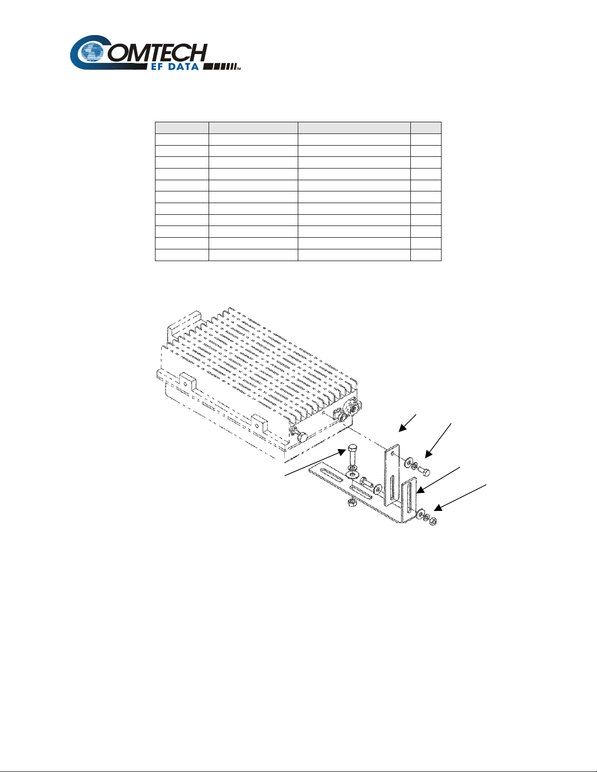
Table 3-1. Optional: BUC Mounting Kit, KT/9930-1
Item Part No. Nomenclature QTY
1 FP/9026-1 Bracket, Lower Block Up 1
2 FP/BR9929-1 Bracket 1
3 HW5/16-18HEXNT Nut, Hex 1
4 HW/5/16-FLT Washer, Flat 1
5 HW/5/16-SPLIT Washer, Split 1
6 HW/5/16-18X1.25 Bolt, Hex-Head 1
7 HW/M4X16PH Screw, Pan-Head 2
8 HW/1/4-20HEXNUT Nut, Hex 1
9 HW/1/4-SPLIT Washer, Split 2
10 HW/1/4-FLT Washer, Flat 3
11 03P1078 Bolt, Hex 1
3
4
5
6
Figure 0-1. Mounting Kit , KT9930-1
2 7
9
10
11
10 (2X)
9
8
Filename: T_ERRATA 2
Page 5

DST
Digital Satellite Terminal System
Operator’s Guide
Comtech EF Data is an ISO 9001
Registered Company
Copyright © Comtech EF Data, 2003. All rights reserved. Printed in the USA.
Comtech EF Data, 2114 West 7th Street, Tempe, Arizona 85281 USA, 480.333.2200, FAX: 480.333.2161.
Part Number MN/DST.IOM
Revision 2
October 19, 2005
Page 6

Digital Satellite Terminal System Revision 2
Preface MN/DST.IOM
Customer Support
Contact the Comtech EF Data Customer Support Department for:
• Product support or training
• Information on upgrading or returning a product
• Reporting comments or suggestions concerning manuals
A Customer Support representative may be reached at:
Comtech EF Data
Attention: Customer Support Department
2114 West 7th Street
Tempe, Arizona 85281 USA
480.333.2200 (Main Comtech EF Data Number)
480.333.4357 (Customer Support Desk)
480.333.2161 FAX
or, E-Mail can be sent to the Customer Support Department at:
service@comtechEF Data.com
Contact us via the web at www.comtechefdata.com
1. To return a Comtech EF Data product (in-warranty and out-of-warranty) for
repair or replacement:
2. Request a Return Material Authorization (RMA) number from the Comtech EF
Data Customer Support Department.
3. Be prepared to supply the Customer Support representative with the model
number, serial number, and a description of the problem.
4. To ensure that the product is not damaged during shipping, pack the product in
its original shipping carton/packaging.
5. Ship the product back to Comtech EF Data. (Shipping charges should be
prepaid.)
For more information regarding the warranty policies, see Warranty Policy, p. xiii.
.
ii
Page 7

Digital Satellite Terminal System Revision 2
Preface MN/DST.IOM
Table of Contents
CHAPTER 1.
1.1 DST Overview.............................................................................................................................................1–1
1.2 Description ..................................................................................................................................................1–3
1.2.1 Description of Indoor Unit .......................................................................................................................1–4
1.2.2 Description of Monitor and Control (M&C)............................................................................................1–4
1.3 Features and Options .................................................................................................................................1–4
1.3.1 Features ....................................................................................................................................................1–4
1.3.2 Options.....................................................................................................................................................1–5
1.4 Specifications ..............................................................................................................................................1–5
CHAPTER 2. INDOOR UNIT INSTALLATION ................................................................................... 2–1
2.1 Unpacking ...................................................................................................................................................2–1
2.2 Equipment Inspection ................................................................................................................................2–2
2.2.1 Included Parts...........................................................................................................................................2–2
2.2.2 Mounting Kit............................................................................................................................................2–3
2.3 Installation ..................................................................................................................................................2–3
2.3.1 IDU Installation........................................................................................................................................2–3
2.3.2 IFL Cable Installation ..............................................................................................................................2–5
2.3.3 Cable Installation .....................................................................................................................................2–6
INTRODUCTION...........................................................................................................1–1
CHAPTER 3. BLOCK UP CONVERTER............................................................................................ 3–1
3.1 Description of the Block Up Converter.....................................................................................................3–1
3.2 LO, Mix and Spectrum Settings................................................................................................................3–3
3.2.1 C-Band .....................................................................................................................................................3–3
3.2.2 Ku-Band...................................................................................................................................................3–4
3.3 BUC Envelope Dimensions and Mounting ...............................................................................................3–5
3.4 ODU Installation.........................................................................................................................................3–6
iii
Page 8

Digital Satellite Terminal System Revision 2
Preface MN/DST.IOM
3.5 BUC Installation .........................................................................................................................................3–6
3.5.1 Mounting Kits ..........................................................................................................................................3–6
3.5.2 Installation................................................................................................................................................3–9
3.6 Spar Mount ...............................................................................................................................................3–10
3.6.1 Ku-BUC Spar Mount, Typical NJRC ....................................................................................................3–10
3.6.2 Ku-Band Spar Mount Typical Terrasant................................................................................................3–11
3.6.3 C-Band Spar Mount, Typical .................................................................................................................3–12
CHAPTER 4. LOW NOISE BLOCK DOWN CONVERTER................................................................ 4–1
4.1 Description ..................................................................................................................................................4–1
4.1.1 Options.....................................................................................................................................................4–2
4.2 LO, Mix and Spectrum Settings (LNB) ....................................................................................................4–3
4.2.1 C-Band .....................................................................................................................................................4–3
4.2.2 Ku-Band...................................................................................................................................................4–4
4.3 Low Noise Block (LNB) Converter ...........................................................................................................4–5
4.4 LNB Installation .........................................................................................................................................4–7
4.4.1 LNB Tooling............................................................................................................................................4–7
4.4.2 C-Band .....................................................................................................................................................4–7
4.4.3 Ku-Band...................................................................................................................................................4–7
4.4.4 Mounting Kits ..........................................................................................................................................4–8
4.4.5 LNB Installation.......................................................................................................................................4–8
4.4.6 TRF Installation .......................................................................................................................................4–9
4.5 Cable Installation......................................................................................................................................4–10
CHAPTER 5. OPERATION ................................................................................................................. 5–1
5.1 Initial Operation .........................................................................................................................................5–1
5.1.1 Prior to Turning On Power.......................................................................................................................5–1
5.1.2 Initial Power Up – Modem Only..............................................................................................................5–2
5.2 LO, Mix and Spectrum (Inversion) Settings ............................................................................................5–3
5.3 Applying Power To The BUC....................................................................................................................5–4
TX Side Setup:............................................................................................................................5–5
5.4 Initial Operation of the Modem with the ODU and LNB .......................................................................5–5
RX Side Setup:............................................................................................................................5–5
APPENDIX A. SELECTING LNBS FOR USE WITH L-BAND MODEMS .......................................... A–1
A.1 Introduction ...............................................................................................................................................A–1
A.1.1 Comparing LNBs................................................................................................................................A–1
A.1.2 Carrier Spacing And Frequency Uncertainty......................................................................................A–2
A.1.3 Frequency Uncertainty Budget ...........................................................................................................A–3
A.1.3.1 Uncertainty For 0.02 ppm Modem and 0.02 ppm BUC .................................................................A–3
iv
Page 9

Digital Satellite Terminal System Revision 2
Preface MN/DST.IOM
A.1.3.2 Uncertainty for 1 ppm Modem and 0.02 ppm BUC.......................................................................A–5
About this Manual.................................................................................................................................................... vii
Related Documents................................................................................................................................................... vii
Conventions and References .................................................................................................................................. vii
Cautions and Warnings...................................................................................................................................... vii
Metric Conversion .................................................................................................................................................... vii
Trademarks ....................................................................................................................................................... viii
Reporting Comments or Suggestions Concerning this Manual............................................................................. viii
Overview of Changes to Revision 1:..................................................................................................................... viii
Electrical Safety ..........................................................................................................................................................ix
Fuses.........................................................................................................................................................................ix
Environmental..........................................................................................................................................................ix
Installation.................................................................................................................................................................x
Telecommunications Terminal Equipment Directive...............................................................................................x
EMC (Electromagnetic Compatibility).....................................................................................................................xi
Warranty Policy....................................................................................................................................................... xiii
Limitations of Warranty........................................................................................................................................ xiii
Exclusive Remedies .............................................................................................................................................. xiii
Disclaimer ............................................................................................................................................................. xiii
Figures
Figure 1-1. Modem with Typical LNB and a 2 Watt BUC...................................................................... 1–2
Figure 1-2. DST System Block Diagram ............................................................................................... 1–3
Figure 2-1. IDU Installation with Optional KT/6228-1 Rear Mounting Bracket. ....................................2–4
Figure 2-2. Typical ODU Unit Installation.............................................................................................. 2–6
Figure 3-1. BUC Envelope .................................................................................................................... 3–5
Figure 3-2. Mounting Kit, KT/9928-1..................................................................................................... 3–7
Figure 4-1. For C-Band: LNB Dimensional Envelope ........................................................................... 4–5
Figure 4-2. For Ku-Band : LNB Dimensional Envelope ........................................................................ 4–6
Figure 4-3. TRF Installation (Ku-Band Shown)..................................................................................... 4–9
Figure A-1. Maximum Carrier Uncertainty, fv, expressed in terms of Symbol Rate, SR .....................A–2
Figure A-2. Minimum Symbol Rate versus Satellite Uncertainty for Ku-Band and C-Band..................A–4
Figure A-3. Multi-Carrier Application With 1 ppm Modem ....................................................................A–5
Figure A-4. Minimum Symbol Rate vs Satellite Uncertainty For Multi-Carrier Applications With a 1.0
ppm Modem ..........................................................................................................................................A–6
v
Page 10

Digital Satellite Terminal System Revision 2
Preface MN/DST.IOM
Tables
Table 1-1. Specifications...........................................................................................................................1–5
Table 1-2. IFL Cable Specifications ..........................................................................................................1–5
Table 2-1. Mounting Components............................................................................................................. 2–2
Table 2-2. Optional: Mounting Kit, KT/6228-1 (IDU to Rack).................................................................... 2–3
Table 2-3. TX Cable Specification (Type N Male Connectors)................................................................. 2–5
Table 2-4. RX Cable Specification (Type F Male Connectors) ................................................................. 2–5
Table 3-1. LO, MIX and Mod Spectrum Settings for Modulator And BUC................................................ 3–3
Table 3-2. LO, MIX and Mod Spectrum Settings for Modulator And BUC................................................ 3–4
Table 3-3. Optional: C-Band Mounting Kit, KT/5738-1 (BUC to OMT) ................................................3–6
Table 3-4. Optional: Ku-Band Mounting Kit, KT/8924-1 (BUC to OMT) ................................................. 3–6
Table 3-5. Optional: C- and Ku-Band Mounting Kit, KT/9928-1 (BUC to Feed Horn) ..............................3–7
Table 4-1. For C-Band: LO and MIX Information for Demodulator and LNB............................................4–3
Table 4-2. For Ku-Band: LO and MIX Information for Demodulator and LNB, Ku-Band.......................... 4–4
Table 4-3. Selection of LNB to OMT .........................................................................................................4–7
Table 4-4. Selection of LNB to OMT .........................................................................................................4–7
Table 4-5. Optional: C-Band Waveguide ASB Kit, KT/2721-1.................................................................. 4–8
Table 4-6. Optional: Ku-Band Mounting Kit, KT/8924-1 (LNB to OMT)................................................... 4–8
vi
Page 11
Digital Satellite Terminal System Revision 2
T
Preface MN/DST.IOM
About this Manual
This manual provides basic installation and operation information for the Comtech EF
Data DST Digital Satellite Terminal System. This is a technical document intended for
earth station engineers, technicians, and operators responsible for the operation and
maintenance of the DST System.
Related Documents
The following documents are referenced in this manual:
• Comtech EF Data UB-530 Universal Breakdown Panel Installation and Operation
Manual
• INTELSAT Earth Station Standards 308, 309, 310, and 314.
• International Telephone Telegraph Consultative Committee V.335 and G.721
Conventions and References
Cautions and Warnings
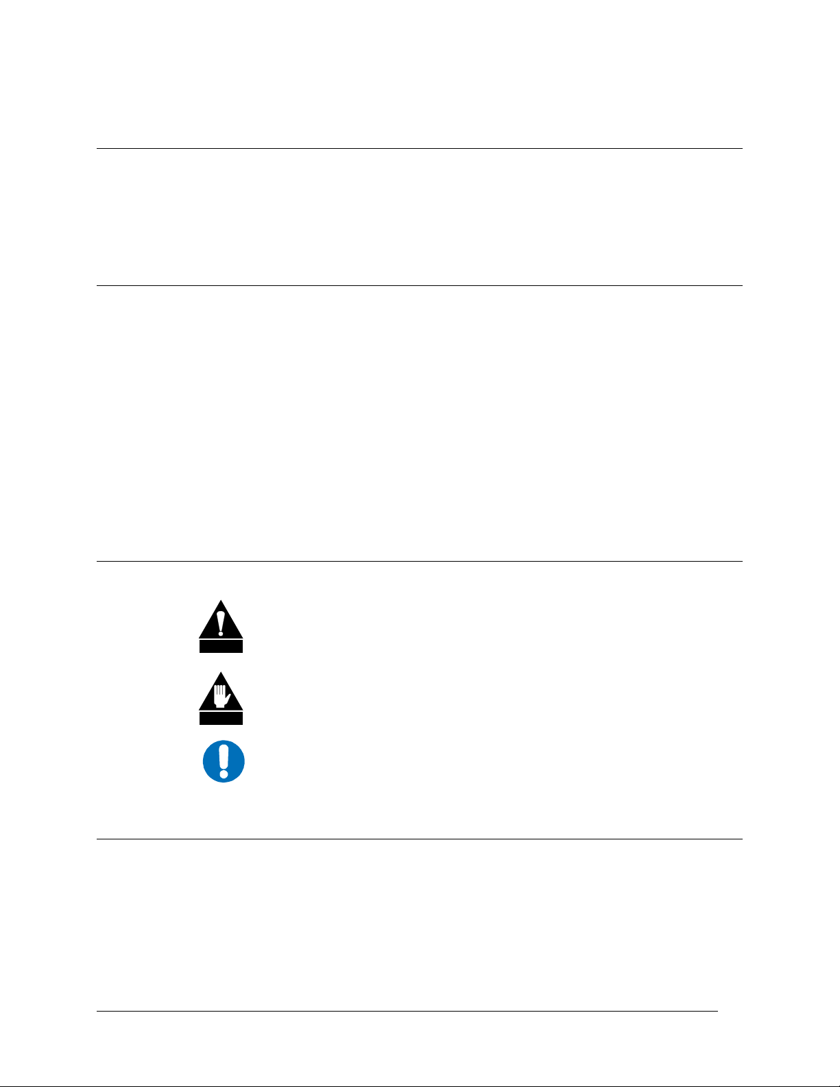
CAUTION indicates a hazardous situation that, if not avoided, may result in
minor or moderate injury. CAUTION may also be used to indicate other
CAUTION
unsafe practices or risks of property damage.
WARNING indicates a potentially hazardous situation that, if not avoided,
could result in death or serious injury.
WARN ING
IMPORTAN
IMPORTANT indicates a statement that is associated with the task being
performed. .
Metric Conversion
Metric conversion information is located on the inside back cover of this manual. This
information is provided to assist the operator in cross-referencing English to Metric
conversions.
vii
Page 12

Digital Satellite Terminal System Revision 2
Preface MN/DST.IOM
Trademarks
Windows is a trademark of Microsoft Corporation.
Other product names mentioned in this manual may be trademarks or registered
trademarks of their respective companies and are hereby acknowledged.
Reporting Comments or Suggestions Concerning this Manual
Comments and suggestions regarding the content and design of this manual will be
appreciated. To submit comments, please contact the Comtech EF Data Customer
Support Department: techpubs@comtechefdata.com
Overview of Changes to Revision 1:
viii
Page 13

Digital Satellite Terminal System Revision 2
Preface MN/DST.IOM
ELECTRICAL SAFETY
The DST Digital Satellite Terminal System has been shown to comply with the following safety
standard:
• EN 60950: Safety of Information Technology Equipment, including electrical business
machines.
The equipment is rated for operation over the range 85 to 264 volts AC. It has a maximum
power consumption of 60 watts.
FUSES
The DST is fitted with two fuses, one each for line and neutral connections. These are contained
within the body of the IEC power connector, behind a small plastic flap.
For continued operator safety, always replace the fuses with the
IMPORTANT
correct type and rating. Refer to the SDM /CiM manual.
Environmental
The DST must not be operated in an environment where the unit is exposed to extremes
of temperature outside the ambient range 0 to 50°C (32 to 122°F), precipitation,
condensation, or humid atmospheres above 95% RH, altitudes (un-pressurised) greater
than 2000 metres, excessive dust or vibration, flammable gases, corrosive or explosive
atmospheres.
Operation in vehicles or other transportable installations that are equipped to provide a
stable environment is permitted. If such vehicles do not provide a stable environment,
safety of the equipment to EN60950 may not be guaranteed.
ix
Page 14
Digital Satellite Terminal System Revision 2
Preface MN/DST.IOM
Installation
The installation and connection to the line supply must be made in compliance to local or
national wiring codes and regulations.
The DST is designed for connection to a power system that has separate ground, line and
neutral conductors. The equipment is not designed for connection to power system that
has no direct connection to ground.
The DST is shipped with a line inlet cable suitable for use in the country of operation. If
it is necessary to replace this cable, ensure the replacement has an equivalent
specification. Examples of acceptable ratings for the cable include HAR, BASEC and
HOXXX-X. Examples of acceptable connector ratings include VDE, NF-USE, UL, CSA,
OVE, CEBEC, NEMKO, DEMKO, BS1636A, BSI, SETI, IMQ, KEMA-KEUR and
SEV.
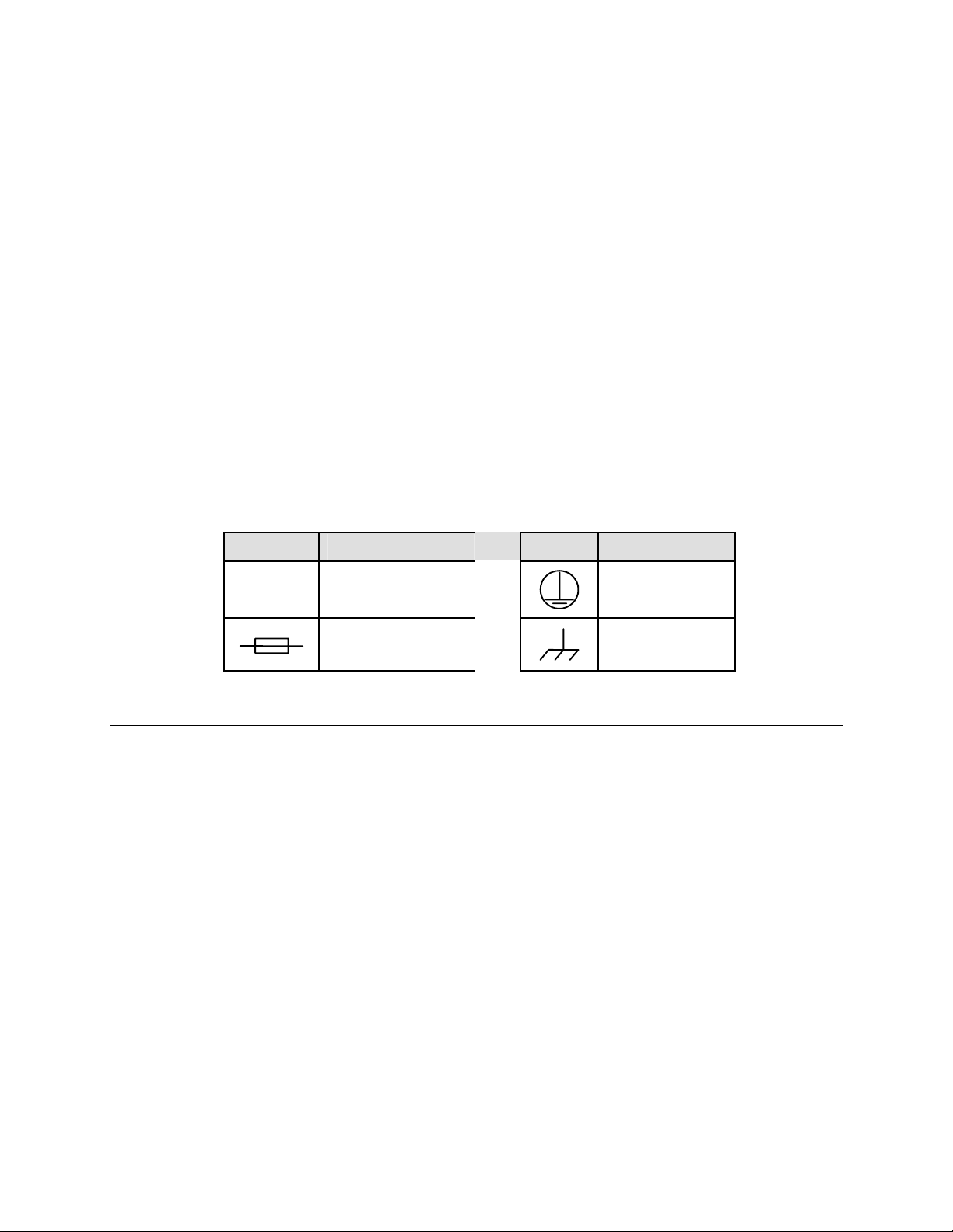
International Symbols:
Symbol Definition Symbol Definition
~
Alternating Current
Fuse
Telecommunications Terminal Equipment Directive
In accordance with the Telecommunications Terminal Equipment Directive 91/263/EEC,
this equipment should not be directly connected to the Public Telecommunications
Network.
Protective Earth
Chassis Ground
x
Page 15

Digital Satellite Terminal System Revision 2
Preface MN/DST.IOM
EMC (Electromagnetic Compatibility)
In accordance with European Directive 89/336/EEC, the DST has been shown, by
independent testing, to comply with the following standards:
Emissions: EN 55022 Class B - Limits and methods of measurement of radio interference
characteristics of Information Technology Equipment.
(Also tested to FCC Part 15 Class B)
Immunity: EN 50082 Part 1 - Generic immunity standard, Part 1: Domestic, commercial
and light industrial environment.
Additionally, the DST has been shown to comply with the following standards:
EN 61000-3-2 Harmonic Currents Emission
EN 61000-3-3 Voltage Fluctuations and Flicker
EN 61000-4-2 ESD Immunity
EN 61000-4-4 EFT Burst Immunity
EN 61000-4-5 Surge Immunity
EN 61000-4-6 RF Conducted Immunity
EN 61000-4-8 Power frequency Magnetic Field Immunity
EN 61000-4-9 Pulse Magnetic Field Immunity
EN 61000-4-11 Voltage Dips, Interruptions, and Variations Immunity
EN 61000-4-13 Immunity to Harmonics
In order that the Modem continues to comply with these standards,
observe the following instructions:
IMPORTANT
xi
Page 16

Digital Satellite Terminal System Revision 2
Preface MN/DST.IOM
• Connections to the transmit and receive IF ports (Type N and Type F, female,
connectors) should be made using a good quality coaxial cable - for example
RG58/U (50Ω) or RG59/U (75Ω).
• All 'D' type connectors attached to the rear panel must have back-shells that
provide continuous metallic shielding. Cable with a continuous outer shield
(either foil or braid, or both) must be used, and the shield must be bonded to the
back-shell.
• The equipment must be operated with its cover on at all times. If it becomes
necessary to remove the cover, the user should ensure that the cover is correctly
re-fitted before normal operation commences.
xii
Page 17

Digital Satellite Terminal System Revision 2
Preface MN/DST.IOM
Warranty Policy
This Comtech EF Data product is warranted against defects in material and workmanship
for a period of two years from the date of shipment. During the warranty period, Comtech
EF Data will, at its option, repair or replace products that prove to be defective.
For equipment under warranty, the customer is responsible for freight to Comtech EF
Data and all related custom, taxes, tariffs, insurance, etc. Comtech EF Data is responsible
for the freight charges only for return of the equipment from the factory to the customer.
Comtech EF Data will return the equipment by the same method (i.e., Air, Express,
Surface) as the equipment was sent to Comtech EF Data.
Limitations of Warranty
The foregoing warranty shall not apply to defects resulting from improper installation or
maintenance, abuse, unauthorized modification, or operation outside of environmental
specifications for the product, or, for damages that occur due to improper repackaging of
equipment for return to Comtech EF Data.
No other warranty is expressed or implied. Comtech EF Data specifically disclaims the
implied warranties of merchantability and fitness for particular purpose.
Exclusive Remedies
The remedies provided herein are the buyer's sole and exclusive remedies. Comtech EF
Data shall not be liable for any direct, indirect, special, incidental, or consequential
damages, whether based on contract, tort, or any other legal theory.
Disclaimer
Comtech EF Data has reviewed this manual thoroughly in order that it will be an easy-touse guide to your equipment. All statements, technical information, and
recommendations in this manual and in any guides or related documents are believed
reliable, but the accuracy and completeness thereof are not guaranteed or warranted, and
they are not intended to be, nor should they be understood to be, representations or
warranties concerning the products described. Further, Comtech EF Data reserves the
right to make changes in the specifications of the products described in this manual at any
time without notice and without obligation to notify any person of such changes.
If you have any questions regarding your equipment or the information in this manual,
please contact the Comtech EF Data Customer Support Department.
xiii
Page 18

Digital Satellite Terminal System Revision 2
Preface MN/DST.IOM
Notes:
________________________________________________________________________
________________________________________________________________________
________________________________________________________________________
________________________________________________________________________
________________________________________________________________________
________________________________________________________________________
________________________________________________________________________
________________________________________________________________________
________________________________________________________________________
________________________________________________________________________
________________________________________________________________________
________________________________________________________________________
________________________________________________________________________
________________________________________________________________________
________________________________________________________________________
________________________________________________________________________
________________________________________________________________________
________________________________________________________________________
________________________________________________________________________
________________________________________________________________________
________________________________________________________________________
________________________________________________________________________
________________________________________________________________________
________________________________________________________________________
________________________________________________________________________
________________________________________________________________________
________________________________________________________________________
________________________________________________________________________
________________________________________________________________________
________________________________________________________________________
________________________________________________________________________
________________________________________________________________________
________________________________________________________________________
________________________________________________________________________
________________________________________________________________________
________________________________________________________________________
________________________________________________________________________
________________________________________________________________________
________________________________________________________________________
________________________________________________________________________
xiv
Page 19

Chapter 1. INTRODUCTION
This equipment is designed for maximum reliability and performance in C- and/or
Ku-Band applications.
1.1 DST Overview
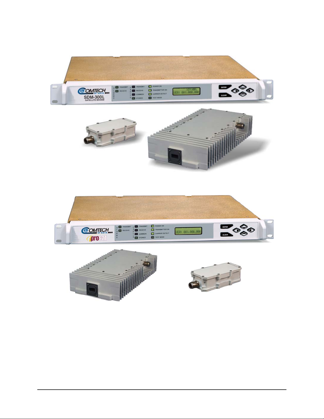
The Digital Satellite Terminal (DST) (Figure 1-1) consists of three major components:
DST iProSat
L-Band Satellite Modem – provides conversion of data to L-
Band and delivers power and a 10 MHz reference signal to
the outdoor equipment.
For additional information. Refer to the modem Installation
and Operations Manual
A Block Up Converter (BUC)
Provides frequency conversion from L-Band to C- or Ku-Band and power amplification to a selectable transmit power level.
A Low Noise Block (LNB) Down Converter
Provides frequency conversion of the received signal from C- or Ku-Band to L-Band and power amplification of the signal
with low levels of noise added.
Internet Enabled L-Band Satellite Modem – provides an
Ethernet data interface, L-Band IF interface and delivers
power and a 10 MHz reference to the outdoor equipment.
For additional information. Refer to the modem Installation
and Operations Manual.
1–1
Page 20
Digital Satellite Terminal System Revision 2
Introduction MN/DST.IOM
Fi
Figure 1-1. Modem with Typical LNB and a 2 Watt BUC
1–2
Page 21

Digital Satellite Terminal System Revision 2
Introduction MN/DST.IOM
1.2 Description
The DST is an integrated, single thread, Single Channel Per Carrier (SCPC), Very Small
Aperture Terminal (VSAT) system designed to meet the needs of a single and/or multiple
site installations.
A block diagram of the DST system is shown in Figure 1-2.
Note: The antenna and the Ortho Mode Transducer (OMT) are not part of the DST
system. The Transmit Reject Filter (TRF), Receive Reject Filter (RRF), and L-Band
Inter-Facility Link (IFL) cables are optional equipment as are mounts.
M&C
M&C
Data
Data
Interfac e
Interfa ce
ODU
ODU
Power Supply
Power Supply
Modulator
Modulator
Demodulator
Demodulator
Tx IF
Rx IF
IFL Cables
(Optional)
BUC
Mounting Kits Optional
Rx Reject
(Optional)
Tx Reject
LNB
LNB
Tx Reject
(Optional)
(Optional)
Filter
Filter
Filter
L-Band Modem
Feed Horn, O MT And
Antenna Not Provided
Figure 1-2. DST System Block Diagram
1–3
Page 22

Digital Satellite Terminal System Revision 2
Introduction MN/DST.IOM
1.2.1 Description of Indoor Unit
The IDU for the DST is one of several L-Band Satellite Modes produced by Comtech EF
Data. The modem provides the data interface and connects to the ODUs at L-Band
frequencies. In addition, the modem provides the M&C interface for the DST system, a
10 MHz reference, and power for both the BUC and the LNB. The DST employs a userfriendly M&C interface that is accessible from either the front panel of the indoor unit
(IDU) or its remote port.
For additional modem information, refer to Installation and Operation Manual for the
modem being used.
1.2.2 Description of Monitor and Control (M&C)
The DST employs the user-friendly monitor and control (M&C), which is accessible
from either the front panel or the remote port of the modem. The DST M&C is primarily
LAN based using Telnet, SNMP or a web browser:
• Data rate and code rate
• ODU power supply On/Off for BUC and LNB
• Hi/Lo ODU current alarm for BUC and LNB current
• 10 MHz Reference On/Off for BUC and LNB
• TX Carrier On/Off
• TX Carrier outdoor power level using modem power offset
• C- or Ku-Band TX and RX frequency programming
• Link power control using the optional AUPC
• FSK monitor and control of FSK capable BUCs, including power leveling
1.3 Features and Options
1.3.1 Features
The DST is designed for maximum performance and reliability for VSAT applications,
including:
• Point-to-point to multipoint links
• Symmetric and Asymmetric Networks
• Internet and router connectivity
• Automatic Uplink Power Control (AUPC) enhanced links
1–4
Page 23

Digital Satellite Terminal System Revision 2
Introduction MN/DST.IOM
1.3.2 Options
The DST includes the following options:
How Enabled IDU Options
Hardware + Fast See modem manual for additional details
Hardware 24 VDC 100W AC ODU (BUC) Power Supply
Hardware 48 VDC 150W AC ODU (BUC) Power Supply
Hardware BUC power 2 watts
Hardware BUC power 5 watts
Hardware BUC power 10 watts
Hardware IFL Cables
Hardware LNB 3.625 to 4.200 GHz
Hardware TX Reject Filter
Hardware Mounting Kits
1.4 Specifications
The following tables list the system and individual component specifications.
Table 1-1. Specifications
IDU Specifications Refer to modem Installation and Operation Manual
Block Up Converter (BUC) Contact Comtech EF Data Customer Support department.
Low Noise Block (LNB) Converter Contact Comtech EF Data Customer Support department.
Serial Interface EIA-232 or EIA-485 (2- or 4-wire)
M&C Items TX Frequency
Configuration Retention At least 1 year without power
FSK Serial Communications Refer to modem Installation and Operation Manual
Parameter Specification
Remote Control Specifications
TX Power
Data Rate Select
Scrambler (On/Off)
RX Carrier Detect
Power Supply Voltages
Plesiochronous Buffer
FSK parameters
BUC FSK Communications
RX Frequency
Transmitter On/Off
Data Loopback
IF Loopback (L-Band)
RAW Corrected Eb/No
RX Signal Level
Fault Status
Error Threshold Alarm
Table 1-2. IFL Cable Specifications
Parameter Specification
Construction Double-Shielded Coaxial
TX Cable Connector Type N Male Connectors
RX Cable Connector Refer to Modem manual.
Insertion Loss 1.0 dB/10 feet max
VSWR 1.25:1
Adapter CN/F-N-ADPMF
Type F Male to Type N Female - Adapts Type N Cable modems with
Type F RX Connector.
1–5
Page 24

Digital Satellite Terminal System Revision 2
Introduction MN/DST.IOM
Notes:
________________________________________________________________________
________________________________________________________________________
________________________________________________________________________
________________________________________________________________________
________________________________________________________________________
________________________________________________________________________
________________________________________________________________________
________________________________________________________________________
________________________________________________________________________
________________________________________________________________________
________________________________________________________________________
________________________________________________________________________
________________________________________________________________________
________________________________________________________________________
________________________________________________________________________
________________________________________________________________________
________________________________________________________________________
________________________________________________________________________
________________________________________________________________________
________________________________________________________________________
________________________________________________________________________
________________________________________________________________________
________________________________________________________________________
________________________________________________________________________
________________________________________________________________________
________________________________________________________________________
________________________________________________________________________
________________________________________________________________________
________________________________________________________________________
________________________________________________________________________
________________________________________________________________________
________________________________________________________________________
________________________________________________________________________
________________________________________________________________________
________________________________________________________________________
________________________________________________________________________
________________________________________________________________________
________________________________________________________________________
________________________________________________________________________
________________________________________________________________________
1–6
Page 25

Chapter 2. INDOOR UNIT
This chapter provides installation and IDU mounting instructions for the DST.
2.1 Unpacking
The DST and manual are packaged in pre-formed, reusable, cardboard cartons containing
foam spacing for maximum shipping protection.
Do not use any cutting tool that will extend more than 1 inch (2.5 cm) into
the container. This can cause damage to the modem.
CAUTION
Unpack the DST as follows:
1. Cut the tape at the top of the carton indicated by OPEN THIS END.
2. Remove the cardboard/foam space covering the unit.
3. Remove the unit, manual, and power cord from the carton.
4. Save the packing material for storage or reshipment purposes.
5. Inspect the equipment for any possible damage incurred during shipment.
6. Check the equipment against the packing list to ensure the shipment is correct.
INSTALLATION
2–1
Page 26

Digital Satellite Terminal System Revision 2
Installation MN/DST.IOM
2.2 Equipment Inspection
2.2.1 Included Parts
A typical Satellite Terminal System contains the following components:
Notes:
1. Parts are not drawn to scale.
2. Because each installation can be customized, this manual will provide
instructions for installing the universal mounting kit.
Table 2-1. Mounting Components
Qty Description Qty Description
1 DST Components
2 Cable Assembly – Transmit (Optional)
1 Installation and Operation Manual
1 Envelope containing the test data
Comtech EF Data Part No. CA/6357-50, 100, -150, -175, or -200
2 Cable Assembly – Receive (Optional)
Comtech EF Data Part No. CA/9645-50, 100, -150, -175, or -200
1 IDU Mounting Bracket (Optional)
FP/6138-1 From Comtech EF Data Kit
KT/6228-1
2–2
Page 27

Digital Satellite Terminal System Revision 2
Installation MN/DST.IOM
2.2.2 Mounting Kit
Table 2-2. Optional: Mounting Kit, KT/6228-1 (IDU to Rack)
QTY Part Number Description
2
4 HW/10-32x1/2RK Bolt, #10 Rack
2 HW/10-32X1/4 SHC Screw, Socket 10-32 x 1/4inch
FP/6138-1 Bracket, Rear Support
2.3 Installation
2.3.1 IDU Installation
Tools Required:
Screw Driver
5/32-inch
Phillips
SAE Allen Wrench
Refer to Figure 2-1. Use mounting kit KT/6228-1.
1. Install the IDU rear support brackets as follows:
a. Install provided rear support bracket onto the mounting rail of the rack.
Fasten with provided bracket bolts.
b. Fasten the provided #10 socket head screws to the rear-side mounting holes
on either side of the chassis modem. Mount the modem into the equipment
rack ensuring that the socket heads engage into the slots of the rear support
brackets.
Note: It may be necessary to adjust the location of the rear mounting rails of
the rack.
c. Refer to Chapter 3 prior to connecting.
2–3
Page 28

Digital Satellite Terminal System Revision 2
U
Installation MN/DST.IOM
Equipment
Rack
Mounting
Rail
#10 Socket head
*
screw
BRACKET
*
BOLTS
Support
*
Bracket
* Note: Components of mounting kit KT/6228-1
ID
Figure 2-1. IDU Installation with Optional KT/6228-1 Rear Mounting Bracket.
2–4
Page 29

Digital Satellite Terminal System Revision 2
Installation MN/DST.IOM
2.3.2 IFL Cable Installation
Comtech EF Data recommends the use of a high-performance cable
assembly for the DST . Manufacturer recommends the cable not exceed 300
CAUTION
Refer to Tables 2-5 and 2-6 and for IFL Cables that are available from the factory.
CAUTION
CA/6357-50
CA/6357-100
CA/6357-150
CA/6357-175
CA/6357-200
feet in length. A non-high-performance cable assembly may result in
damage to the IDU, BUC, or LNB.
Prior to connecting the cables, ensure that the ODU and LNB voltages have
been switched off.
Table 2-3. TX Cable Specification (Type N Male Connectors)
Length Part No.
feet meters
50 ± 2 15.2 ± 0.7
100 ± 3 30 ± 1
150 ± 3 46 ± 1
175 ± 3 53± 1
200 ± 3 61 ± 1
Frequency,
GHz
2 1.25:1 1.0 dB/10 feet
2 1.25:1 1.0 dB/10 feet
2 1.25:1 1.0 dB/10 feet
2 1.25:1 1.0 dB/10 feet
2 1.25:1 1.0 dB/10 feet
VSWR Insertion Loss, max
Table 2-4. RX Cable Specification (Type F Male Connectors)
CA/9645-50
CA/9645-100
CA/9645-150
CA/9645-175
CA/9645-200
Length Part No.
feet meters
50 ± 2 15.2 ± 0.7
100 ± 3 30 ± 1
150 ± 3 46 ± 1
175 ± 3 53± 1
200 ± 3 61 ± 1
Frequency,
GHz
2 1.25:1 1.0 dB/10 feet
2 1.25:1 1.0 dB/10 feet
2 1.25:1 1.0 dB/10 feet
2 1.25:1 1.0 dB/10 feet
2 1.25:1 1.0 dB/10 feet
VSWR Insertion Loss, max
Notes:
1. The TX cable above has Type N connectors and was used for both TX and RX with the
SDM-300L2 and early revisions of the CiM-300L in conjunction with LNBs that have
Type N Connectors.
2. The SDM-300L3 and later revisions of the CiM-300L modems use a Type N connector
for TX and a Type F connector for RX and use the cables listed above.
3. Equivalent cables/supplies may be used.
4. The DST is manufactured to accommodate a TX attenuation of 20 dB maximum between
the IDU and ODU, and a RX attenuation of 25 dB maximum between the IDU and RX
LNB.
2–5
Page 30

Digital Satellite Terminal System Revision 2
Installation MN/DST.IOM
2.3.3 Cable Installation
Note: Prior to connecting the cables, ensure that the ODU and LNB voltages have been
switched off.
1. Connect RX L-Band cable from the LNB to the IDU CP3 connector.
2. Connect TX L-Band cable from the BUC to the IDU CP1 connector.
Upper
Bracket
TX L-band
RX L-band
Cable
Lower “L”
Bracket
Cable
LNB
BUC
TRF
Figure 2-2. Typical ODU Unit Installation
.
2–6
Page 31

Digital Satellite Terminal System Revision 1
Block Up Converter MN/DST.IOM
Chapter 3. BLOCK UP
CONVERTER
This chapter provides the description, operation, specification, and installation of a Block
Up Converter (BUC)
3.1 Description of the Block Up Converter
The Block Up Converter (BUC) translates the L-Band carrier output from the IDU (in the
950 to 1750 MHz range) to C- or Ku-Band frequencies typically between:
• C-Band: 5.845 and 6.425 GHz and amplifies the carrier to the desired TX power
level.
• Ku-Band: 14.0 and 14.5 GHz and amplifies the carrier to the desired TX power
level.
The local oscillator of the BUC locks to the 10 MHz reference signal from the IDU in
order to provide an accurate frequency translation. In the event the BUC cannot lock to
the 10 MHz reference, the output carrier is muted to prevent interference with adjacent
carriers.
3–1
Page 32

Digital Satellite Terminal System Revision 1
Block Up Converter MN/DST.IOM
Notes :
________________________________________________________________________
________________________________________________________________________
________________________________________________________________________
________________________________________________________________________
________________________________________________________________________
________________________________________________________________________
________________________________________________________________________
________________________________________________________________________
________________________________________________________________________
________________________________________________________________________
________________________________________________________________________
________________________________________________________________________
________________________________________________________________________
________________________________________________________________________
________________________________________________________________________
________________________________________________________________________
________________________________________________________________________
________________________________________________________________________
________________________________________________________________________
________________________________________________________________________
________________________________________________________________________
________________________________________________________________________
________________________________________________________________________
________________________________________________________________________
________________________________________________________________________
________________________________________________________________________
________________________________________________________________________
________________________________________________________________________
________________________________________________________________________
________________________________________________________________________
________________________________________________________________________
________________________________________________________________________
________________________________________________________________________
________________________________________________________________________
________________________________________________________________________
________________________________________________________________________
________________________________________________________________________
________________________________________________________________________
________________________________________________________________________
________________________________________________________________________
3–2
Page 33

Digital Satellite Terminal System Revision 1
Block Up Converter MN/DST.IOM
3.2 LO, Mix and Spectrum Settings
3.2.1 C-Band
Table 3-1. LO, MIX and Mod Spectrum Settings for Modulator And BUC
P1dB_min
5 Watt C Yes RF/BUC05C-A-F-T 5.850 6.425 7,375.00 - Invert 24 VDC KT/8924-1 KT/9027-1
10 Watt C Yes RF/BUC10C-A-F-T 5.850 6.425 7,375.00 - Invert 48 VDC TBD TBD
1 Watt C No RF/BUC01C-A-N-N 5.850 6.425 4,900.00 + Normal 24 VDC KT/8924-1 KT/9027-1
2 Watt C No RF/BUC02C-A-N-N 5.850 6.425 4,900.00 + Normal 24 VDC KT/8924-1 KT/9027-1
5 Watt C No RF/BUC05C-A-N-N 5.850 6.425 4,900.00 + Normal 24 VDC KT/8924-1 KT/9027-1
2 Watt Ext C No RF/BUC02C-B-N-N 6.725 7.025 5,760.00 + Normal 24 VDC KT/8924-1 KT/9027-1
5 Watt Ext C No RF/BUC05C-B-N-N 6.725 7.025 5,760.00 + Normal 24 VDC KT/8924-1 KT/9027-1
Band
FSK
CEFD Part #
RF Start
Frequency
(GHz)
RF End
Frequency
(GHz)
LO (Offset)
Freq.
(MHz)
Mix
(±)
Modem
Spectrum
(Utility
Modulator
Menu)
Supply
Voltage
Spar
Mount Kit
Feed
Mount Kit
3–3
Page 34

Digital Satellite Terminal System Revision 1
Block Up Converter MN/DST.IOM
3.2.2 Ku-Band
Table 3-2. LO, MIX and Mod Spectrum Settings for Modulator And BUC
P1dB_min
*2 Watt Ku Yes RF/BUC02KU-A-F-T 14.00 14.50 13,050.00 + Normal 24 VDC KT/8924-1 KT/9928-1
*4 Watt Ku Yes RF/BUC04KU-A-F-T 14.00 14.50 13,050.00 + Normal 24 VDC KT/8924-1 KT/9928-1
*8 Watt Ku Yes RF/BUC08KU-A-F-T 14.00 14.50 13,050.00 + Normal 48 VDC KT/8924-1 KT/9928-1
**1 Watt Ku No RF/BUC01KU-A-N-N 14.00 14.50 13,050.00 + Invert 24 VDC KT/8924-1 KT/9928-1
**2 Watt Ku No RF/BUC02KU-A-N-N 14.00 14.50 13,050.00 + Invert 24 VDC KT/8924-1 KT/9928-1
**4 Watt Ku No RF/BUC04KU-A-N-N 14.00 14.50 13,050.00 + Invert 24 VDC KT/8924-1 KT/9928-1
*2 Watt Ext Ku Yes RF/BUC02KU-B-F-T 13.75 14.25 12,800.00 + Normal 24 VDC KT/8924-1 KT/9928-1
*4 Watt Ext Ku Yes RF/BUC04KU-B-F-T 13.75 14.25 12,800.00 + Normal 24 VDC KT/8924-1 KT/9928-1
* 8 Watt Ext Ku Yes RF/BUC08KU-B-F-T 13.75 14.25 12,800.00 + Normal 48 VDC KT/8924-1 KT/9928-1
**1Watt
(Typical)
28 dBm)
**2 Watt Ext Ku No RF/BUC02KU-B-N-N 13.75 14.25 15,200.00 - Invert 24 VDC KT/8924-1 KT/9928-1
Band
Ext Ku No RF/BUC01KU-B-N-N 13.75 14.25 15,200.00 - Invert 24 VDC KT/8924-1 KT/9928-1
FSK
CEFD Part #
RF Start
Frequency
(GHz)
RF End
Frequency
(GHz)
LO (Offset)
Freq.
(MHz)
Mix
(+/-)
Modem
Spectrum
(Utility
Modulator
Menu)
Supply
Voltage
Spar
Mount Kit
Feed
Mount Kit
* Option A BUC Mounting
** Option B BUC Mounting
3–4
Page 35

Digital Satellite Terminal System Revision 1
Block Up Converter MN/DST.IOM
3.3 BUC Envelope Dimensions and Mounting
Notes:
1. Dimensions are listed in inches and centimeters are in parentheses.
2. This figure is a typical configuration. For specific applications, contact Comtech
EF Data, Customer Support department.
Figure 3-1. BUC Envelope
3–5
Page 36

Digital Satellite Terminal System Revision 1
Block Up Converter MN/DST.IOM
3.4 ODU Installation
Refer to Figure 3-2.
1/2-inch
5/16-inch
7/16-inch
7/64-inch
M3
Screw Driver
Box Wrench (or adjustable)
Box Wrench (or adjustable)
Box Wrench (or adjustable)
SAE Allen
Metric Allen Wrench
Phillips
3.5 BUC Installation
After removing the protective covers, ensure that no foreign material or
CAUTION
moisture enter
3.5.1 Mounting Kits
Table 3-3. Optional: C-Band Mounting Kit, KT/5738-1
QTY Part No. Nomenclature
8
03P1097 Bolt, Hex, 10-32x1, SS
1 FP/5195 Gasket, CPR137-FULL
8 HW/1-32HEXNUT Nut, Hex, 10-32, SS
16 HW/10-FLT Washer, Flat, No. 10, SS
8 HW/10-SPLIT Washer, Split Lock, No. 10, SS
1 HW/GKT-CPR137G Gasket, CPR137-Half
Table 3-4. Optional: Ku-Band Mounting Kit, KT/8924-1
QTY Part No. Nomenclature
3
32P1037 O-Ring
3 32P1039 O-Ring
4 HW/6-32 HEXNUT #6 Nut
4 HW/6-32x7/8 SHCS #6 Socket screw
8 HW/6-FLT #6 Washer, Flat
4 HW/6-SPLIT #6 Washer, Split
8 HW/8-FLT #8 Washer, Flat
8 HW/8-SPLIT #8 Washer, Split
4 HW/M4x12SHCS M4 x 12 Socket Screw
4 HW/M4x25SHCS M4 x 25 Socket Screw
(BUC to OMT)
(BUC to OMT)
3–6
Page 37

Digital Satellite Terminal System Revision 1
Block Up Converter MN/DST.IOM
Table 3-5. Optional: C- and Ku-Band Mounting Kit, KT/9928-1
(BUC to Feed Horn)
Item Part No. Nomenclature QTY Remarks **
1 FP/9026-1 Bracket, QP 1
2 FP/BR9927-1 Bracket, Upper 1 Used with Option B BUC
3 HW/M4FLAT Washer, Flat 2 Used with Option B BUC
4 HW/M4LOCK Washer, Lock 4 Used with Option B BUC
5 HW/M4X16PH Screw, Pan Head Phillips 2 Used with Option B BUC
6 HW/1/4-FLAT Washer, Flat 2
7 HW/1/4-SPLIT Washer, Split 2
8 03P1078 Bolt, Hex 1
9 HW/1/4-20HEXNUT Nut, Hex 1
10 FP/BR9929-1 Bracket 1 Used with Option A BUC
11 HW/1/4-20X5/8HEX Screw, Hex 1 Used with Option A BUC
*12 thru 19 Not Used
20 HW/5/16-FLT Washer, Flat 1
21 HW/5/16-18X1.25 Bolt, HEX Head 1
22 HW/5/16-SPLIT Washer, Split 1
23 HW/5/16-18HEXNT Nut, Hex 1
* Not Illustrated.
** Refer to Table 3-3
Figure 3-2. Mounting Kit, KT/9928-1
3–7
Page 38

Digital Satellite Terminal System Revision 1
Block Up Converter MN/DST.IOM
Table 3-6. Optional: BUC Mounting Kit, KT/10361-1
Item Part No. Nomenclature QTY
1 FP/9026-1 Bracket, Lower Block Up 1
2 FP/BR9927-1 Bracket, Upper 1
3 HW5/16-18HEXNT Nut, Hex 1
4 HW/5/16-FLT Washer, Flat 1
5 HW/5/16-SPLIT Washer, Split 1
6 HW/5/16-18X1.25 Bolt, Hex-Head 1
7 HW/M4X16PH Screw, Pan-Head 2
8 HW/1/4-20HEXNUT Nut, Hex 1
9 HW/1/4-SPLIT Washer, Split 2
10 HW/1/4-FLT Washer, Flat 3
11 03P1078 Bolt, Hex 1
12 HW/M4LOCK Washer, Lock 2
13 HW/M$FLAT Washer, Flat 2
2
13 (2X)
12 (2X)
7 (2X)
11
6
5
4
10 (2X)
9
8
3
1
Figure 3-3. BUC Mounting Kit, KT/10361-1
3–8
Page 39

Digital Satellite Terminal System Revision 1
Block Up Converter MN/DST.IOM
3.5.2 Installation
To install the BUC to the antenna:
1. If installed: Remove protective covers from the antenna OMT and SSPA.
After removing the protective covers, ensure that no foreign
material or moisture enters the antenna waveguide or BUC.
CAUTION
2. Install the appropriate gasket (from KT/8924-1 or KT/5738-1) on the antenna
OMT, as follows:
a. If only one of the mating flanges is grooved, the thin gasket should be
installed.
b. If both of the mating flanges are grooved, the thick gasket should be
installed.
3. Position the SSPA (with gasket) in place on the antenna, and install with
provided socket screws and washers (split and flat) from mounting kit.
4. Install ODU Mounting Kit KT/9928-1, as follows:
Option A BUC
a. Install bracket (10, Figure 3-2) to BUC and secure with flat washer (6), split
washer (7), and screw (11).
b. Position universal lower ‘L’ bracket (1) to feed horn, loosely fasten with bolt
(21), flat washer (20), lock washer (22), and nut (23).
c. Align bracket (1) with bracket (10) to adjust the position of the BUC.
d. Insert bolt (8) with flat washer (6) through bracket (1, 10) and secure with
flat washer (6), split washer (7), and nut (9).
e. Tighten all hardware.
Option B BUC
a. Install bracket (2, Figure 3-2), to BUC and secure with two screws (5), two
lock washer washers (4), two flat washers (3).
b. Position universal lower ‘L’ bracket (1) to feed horn, loosely fasten with bolt
(21), flat washer (20), lock washer (22), and nut (23).
c. Align bracket (1) with bracket (2) to adjust for position of the BUC.
f. Insert bolt (8) with flat washer (6) through bracket (1, 10) and secure with
flat washer (6), split washer (7), and nut (9).
d. Tighten all hardware.
3–9
Page 40

Digital Satellite Terminal System Revision 1
Block Up Converter MN/DST.IOM
3.6 Spar Mount
3.6.1 Ku-BUC Spar Mount, Typical NJRC
1
1. KT/11125 KIT, BUC SPAR Mount, Ku-Band RF
-2. KT/9928-1 . Kit, BUC, Mount 1
-3. FP/BR11119-1 . Bracket, BUC Mount 1
-4. FP/BR11120-1 . Bracket, Mounting Plate 2
-5. HW/5/16-18HEXNUT . Nut, Hex 20
-6. HW/5/16/18x1.25 . Bolt, Hex 12
-7. HW/5/16-FLT . Washer, Flat 20
-8. HW/5/16-SPLIT . Washer, Split 20
-9. HW/5/16-18x2.25 . Bolt, Hex 8
- Item Not Illustrated.
Figure 3-4. Ku-BUC Spar Mount, Typical NJRC
3–10
Page 41

Digital Satellite Terminal System Revision 1
Block Up Converter MN/DST.IOM
3.6.2 Ku-Band Spar Mount Typical Terrasant
1
1. KT/11125 KIT, BUC SPAR Mount, Ku-Band RF
-2. KT/9928-1 . Kit, BUC, Mount 1
-3. FP/BR11119-1 . Bracket, BUC Mount 1
-4. FP/BR11120-1 . Bracket, Mounting Plate 2
-5. HW/5/16-18HEXNUT Nut, Hex 20
-6. HW/5/16/18x1.25 . Bolt, Hex 12
-7. HW/5/16-FLT . Washer, Flat 20
-8. HW/5/16-SPLIT . Washer, Split 20
-9. HW/5/16-18x2.25 . Bolt, Hex 8
- Item Not Illustrated.
Figure 3-5. Ku-BUC Spar Mount, Typical Terrasat
3–11
Page 42

Digital Satellite Terminal System Revision 1
Block Up Converter MN/DST.IOM
3.6.3 C-Band Spar Mount, Typical
1
1. KT/11124 KIT, BUC SPAR Mount, C-Band RF
-2. KT/9928-1 . Kit, BUC, Mount 1
-3. FP/BR11118-1 . Bracket, BUC Mount 1
-4. FP/BR11120-1 . Bracket, Mounting Plate 2
-5. HW/5/16-18HEXNUT . Nut, Hex 20
-6. HW/5/16/18x1.25 . Bolt, Hex 12
-7. HW/5/16-FLT . Washer, Flat 20
-8. HW/5/16-SPLIT . Washer, Split 20
-9. HW/5/16-18x2.25 . Bolt, Hex 8
- Item Not Illustrated.
Figure 3-6. C-Band Spar Mount, Typical
3–12
Page 43

Chapter 4. LOW NOISE BLOCK
This chapter provides the description and operation for a LNB.
4.1 Description
The LNB amplifies the input Ku-Band signal and down converts it to L-Band in the
range of 950 to 1750 MHz (there may be instances that the L-Band range = 950 to 1450
MHz ). The choice of which downlink frequency band is determined by the selection of
a frequency range, usually from one of LNBs in the following bands:
For C-Band For Ku-Band
3.625 to 4.2 GHz
4.50 to 4.80 GHz
LNBs are available that are either externally referenced (EXT REF) or internally
referenced (INT REF).
• The EXT REF LNB accepts an external 10 MHz reference from the IDU. These
units have the best phase noise performance and the lowest frequency drift.
• The INT REF LNB includes its own internal oscillator. DC power is supplied to
the LNB through the IFL cable from the IDU.
The standard LNB noise temperature is: For C-Band < 35°K.
For Ku- Band < 65°K.
Optional: A TX Reject Filter (TRF) may be obtained with the system or supplied by
the customer.
DOWN CONVERTER
10.95 to 11.70 GHz
11.70 to 12.20 GHz
12.25 to 12.75 GHz
4–1
Page 44

Digital Satellite Terminal System Revision 1
Low Noise Block Converter MN/DST.IOM
4.1.1 Options
Hardware
Hardware
Hardware
Hardware
IFL Cables
Externally Referenced from IDU or Internally Referenced
TX Reject Filter
Mounting Kits
4–2
Page 45

Digital Satellite Terminal System Revision 1
Low Noise Block Converter MN/DST.IOM
4.2 LO, Mix and Spectrum Settings (LNB)
4.2.1 C-Band
Table 4-1. For C-Band: LO and MIX Information for Demodulator and LNB
LNB Part No.
RF/LNB-C-55-35N 3.625 – 4.200 GHz
RF/LNB3.6-4.2FE 3.625 – 4.200 GHz
RF/LNB3.6-4.2F03 3.625 – 4.200 GHz
XXXXXXXXXXXXX 3.400 – 4.200 GHz 5,150.00 - 3,400.00 4,200.00 1,525.00 950.00 Invert 18 Type F
XXXXXXXXXXXXX 4.500 – 4.800 GHz 5,760.00 - 4,500.00 4,500.00 1,525.00 950.00 Invert 18 Type F
Description
Ext Ref
Ext Ref
Ext Ref
LO (Offset)
Frequency
(MHz)
5,150.00 - 3,625.00 4,200.00 1,525.00 950.00 Invert 18 Type N
5,150.00 - 3,625.00 4,200.00 1,525.00 950.00 Invert 18 Type F
5,150.00 - 3,625.00 4,200.00 1,525.00 950.00 Invert 18 Type F
MIX
(+/-)
Min
LNB
Satellite
Frequency
(MHz)
Max
LNB
Satellite
Frequency
(MHz)
L-Band
Frequency
At
LNB Min
(MHz)
L-Band
Frequency
At
LNB Max
(MHz)
Demod
Spectrum
(Utility
Demod
Menu)
Operating
Voltage, V
RF
Connector
4–3
Page 46

Digital Satellite Terminal System Revision 1
Low Noise Block Converter MN/DST.IOM
4.2.2 Ku-Band
Table 4-2. For Ku-Band: LO and MIX Information for Demodulator and LNB, Ku-Band
LNB Part No.
RF/LNB-10.9-11.7FE 10.95 – 11.7 GHz
RF/LNB-11.7-12.2FE 11.7 – 12.2 GHz
RF/LNB-12.2-12.7FE 12.25 - 12.75 GHz
RF/LNB-10.9-11.7F03 10.95 – 11.7 GHz
RF/LNB-11.7-12.2F03 11.7 – 12.2 GHz
RF/LNB-12.2-12.7F03 12.25 - 12.75 GHz
Description
Ext Ref
Ext Ref
Ext Ref
± 3 ppm
± 3 ppm
± 3 ppm
LO (Offset)
Frequency
(MHz)
10,000.00 + 10,950.00 11,700.00 950.00 1700.00 Normal 18 Type F
10,750.00 + 11,700.00 12,200.00 950.00 1450.00 Normal 18 Type F
11,300.00 + 12,250.00 12,750.00 950.00 1450.00 Normal 18 Type F
10,000.00 + 11,200.00 11,700.00 950.00 1450.00 Normal 18 Type F
10,750.00 + 10,950.00 11,700.00 950.00 1700.00 Normal 18 Type F
11,300.00 + 12,250.00 12,750.00 950.00 1450.00 Normal 18 Type F
MIX
(+/-)
Min
LNB
Satellite
Frequency
(MHz)
Max
LNB
Satellite
Frequency
(MHz)
L-Band
Frequency
At
LNB Min
(MHz)
L-Band
Frequency
At
LNB Max
(MHz)
Demod
Spectrum
(Utility
Demod
Menu)
Operating
Voltage, V
RF
Connector
4–4
Page 47

Digital Satellite Terminal System Revision 1
Low Noise Block Converter MN/DST.IOM
4.3 Low Noise Block (LNB) Converter
Refer to Figure 4-1 for the LNB dimensional envelope drawing.
Notes:
1. Dimensions are listed in inches and centimeters are in parentheses.
2. This figure is typical of the LNB configurations. For specific applications,
contact Comtech EF Data, Customer Support department.
(1.69)
(.54)
(1.50)
(3.00)
RF OUTPUT
N CONN FEMALE
(8.99)
(7.50)
(.75)
(1.475)
C
L
(2.85)
CPRG229 WAVEGUIDE
RF INPUT
(1.50)
C
L
Figure 4-1. For C-Band: LNB Dimensional Envelope
4–5
Page 48

Digital Satellite Terminal System Revision 1
Low Noise Block Converter MN/DST.IOM
2.563
(6.51)
5.125
(13.02)
1.563
(3.97)
Figure 4-2. For Ku-Band : LNB Dimensional Envelope
4–6
Page 49

Digital Satellite Terminal System Revision 1
Low Noise Block Converter MN/DST.IOM
4.4 LNB Installation
4.4.1 LNB Tooling
Refer to Figure 4-1.
1/2-inch
5/16-inch
7/16-inch
7/64-inch
M3
Screw Driver
Box Wrench (or adjustable)
Box Wrench (or adjustable)
Box Wrench (or adjustable)
SAE Allen
Metric Allen Wrench
Phillips
4.4.2 C-Band
Table 4-3. Selection of LNB to OMT
LNB Part No. LNB
RF/LNB3.6-4.2FE
RF/LNB3.6-4.2F03
4.4.3 Ku-Band
Table 4-4. Selection of LNB to OMT
LNB Part No. LNB
RF/LNB-10.9-11.7
RF/LNB-11.7-12.2
RF/LNB-12.2-12.7
RF/LNB10.9-11.7FE
RF/LNB11.7-12.2FE
RF/LNB12.2-12.7FE
RF/LNB10.9-11.7F03
RF/LNB11.7-12.2F03
RF/LNB12.2-12.7F03
Description
Comment
LNB, EXT REF Type F Connector.
LNB, 3 ppm INT REF Type F Connector.
Comment
Description
LNB, EXT REF Type N Connector. For Spares
or use with SDM-300L2 and
other modems with Type N RF
receive connector.
LNB, EXT REF Type F Connector. Use with
SDM-300L3 / CiM-300L and
other modems with Type F RF
receove connector.
LNB, 3 ppm INT REF Type F Connector. Use with
SDM-300L3 / CiM-300L and
other modems with Type F RF
receive connectors.
4–7
Page 50

Digital Satellite Terminal System Revision 1
Low Noise Block Converter MN/DST.IOM
4.4.4 Mounting Kits
Table 4-5. Optional: C-Band Waveguide ASB Kit, KT/2721-1
QTY Part Number Description
10 03P1079 Bolt, Hex, 1/4-20X1, SS
1 32D1002 Gasket, Half, Waveguide CPR229
1 32P1040 Gasket, Full, Waveguide CPR229
20 HW/1/4-FLT Washer, Flat, 1/4
10 HW/1/4-SPLIT Washer, Split 1/4
10 HW/1/4HEXNUT Nut, Hex 1/4
Table 4-6. Optional: Ku-Band Mounting Kit, KT/8924-1
(LNB to OMT)
QTY Part Number Description
3 32P1037 O-Ring
3 32P1039 O-Ring
4 HW/6-32 HEXNUT #6 Nut
4 HW/6-32x7/8 SHCS #6 Socket screw
8 HW/6-FLT #6 Washer, Flat
4 HW/6-SPLIT #6 Washer, Split
8 HW/8-FLT #8 Washer, Flat
8 HW/8-SPLIT #8 Washer, Split
4 HW/M4x12SHCS M4 x 12 Socket Screw
4 HW/M4x25SHCS M4 x 25 Socket Screw
4.4.5 LNB Installation
To install a single LNB:
1. If installed: Remove the protective covers from the LNB and TRF.
After removing the protective covers, ensure that no foreign
material or moisture enters the antenna waveguide or TRF.
CAUTION
2. Install the appropriate o-ring on the LNB or TRF, as follows:
a. If only one of the mating flanges is grooved, the thin o-ring should be
installed.
b. If both of the mating flanges are grooved, the thick o-ring should be installed.
3. Position the LNB (with o-ring) in place on the antenna OMT and install with
provided M4x12 socket screws and No. 8 SAE washers (split and flat).
4–8
Page 51

Digital Satellite Terminal System Revision 1
Low Noise Block Converter MN/DST.IOM
Note: Flat washers maybe omitted if there is interference with assembly.
4.4.6 TRF Installation
To install the TX Reject Filter to the antenna OMT:
1. If installed; remove protection covers from the OMT and TRF.
After removing the protective covers, ensure that no foreign
material or moisture enters the antenna waveguide or TRF.
CAUTION
2. Install the appropriate gasket (from KT/8924-1 or KT/2721-1)on the antenna
OMT or TRF, as follows:
a. If only one of the mating flanges is grooved, the thin gasket should be
installed.
b. If both of the mating flanges are grooved, the thick gasket should be
installed.
3. Position the TRF (with ogasket) in place on the antenna OMT and install with
provided No. 6 SAE hardware, from Mounting Kit Part No. KT/8924-1 or
KT/2721-1
Figure 4-3. TRF Installation (Ku-Band Shown)
4–9
Page 52

Digital Satellite Terminal System Revision 1
Low Noise Block Converter MN/DST.IOM
4.5 Cable Installation
Care should be exercised in cable installation. Install the cables using the
most direct route and secure with clamps and ties. Avoid all sharp bends.
CAUTION
Cable connectors used in outdoor applications must be sealed to avoid leakage. Moisture
can seep into junctions at the plug end of the connector, between the fixed and movable
parts, and where the cable connects to the connector. Signal attenuation and possible loss
of signal can occur in the presence of moisture. All cable junctions must be sealed with a
self-amalgamating tape, such as 3-M, Type 23 Scotch, or equivalent once installation and
commissioning is complete (user supplied).
Replacement of the cables can be the result.
4–10
Page 53

Chapter 5. OPERATION
This chapter describes the general operation of the RF terminal using the front panel
keys. Detail operation is the same as specified in the SDM-300L3 / CiM-300L
Installation and Operation Manual. For other Comtech EF Data Modems, refer to the
appropriate modem Installation and Operation Manual.
5.1 Initial Operation
Careful setup is necessary to prevent damage to electronic components.
Replacement of a component(s) may be the result.
CAUTION
5.1.1 Prior to Turning On Power
Note: Ensure DST system is installed properly and all connections all secure, except the
L-Band TX and RX IF connectors which are initially disconnected.
Observe the following steps:
Step
No.
1. Make sure prime power to the Modem is removed.
2. Verify the IFL L-Band cables are not connected to the
modem.
Selection / Programming
Menu Location
5–1
Page 54

Digital Satellite Terminal System Revision 1
Operation MN/DST.IOM
5.1.2 Initial Power Up – Modem Only
Initially, the modem is set up and checked out and not connected to the IFL cables:
Note: Refer to the specific modem manual for programming information.
Set the modem for a known operating configuration. This includes some of the steps that
follow.
Step
No.
3. Disconnect the L-Band TX and RX cables from the modem. Not Applicable (NA)
4. Connect prime power to the modem. NA
5. Allow modem to complete initialization. NA
6. ODU Power = OFF Configuration: Modulator
7. Modem Transmitter = ON
(Transmitter ON (Green LED) at front panel LED is On)
8. LNB Power = OFF Configuration: Demodulator
9. IF Loopback = ON (Test Mode LED turns ON). This matches the L-Band
demodulator frequency to the L-Band modulator frequency.
Ensure the Mod Spectrum (Inversion) matches the Demod Spectrum
(Inversion). This is required for the demodulator to lock. See
comments in the paragraph on LO, Mix and Spectrum for loopback
over satellite (RF Loopback).
10. Verify the carrier is locked. (Carrier Detect LED is Green at front panel) Front Panel
11. Make sure all faults are resolved before going forward. Front Panel LEDs and LCD
12. IF Loopback = Off (Test Mode LED turns Off). Configuration: Demodulator
Selection / Programming
Menu Location
Configuration: Modulator
Configuration: Demodulator
Utility: Modulator
Utility: Demodulator
Faults/ Alarms
5–2
Page 55

Digital Satellite Terminal System Revision 1
Operation MN/DST.IOM
5.2 LO, Mix and Spectrum (Inversion) Settings
The SDM-300L3 / CiM-300L Satellite Modem permits programming of terminal
(satellite) frequencies instead of the L-Band frequencies. This is useful because it allows
direct entry of the assigned TX and RX frequencies. Three parameters are adjusted to
setup the modem with the BUC/LNB. These are the:
♦ LO: Local Oscillator Frequency.
♦ Mix Sign: + or -, determines whether the L-Band carrier is added or
subtracted from the LO to translate to the satellite frequency.
♦ Mod Spectrum and Demod Spectrum (Inversion); needed to correct for any
inversion caused by the frequency translation.
• For BUC only. Refer to Chapter 3, for the LO frequencies for BUCs
provided by Comtech EF Data, along with the MIX(+ or -) and
Spectrum (Inversion) for several common frequency bands.
• For LNB only. Refer to Chapter 4, for the LO frequencies for LNBs
provided by Comtech EF Data, along with the MIX(+ or -) and
Spectrum (Inversion) for several common frequency bands
The LO and MIX are entered into the modem to program the satellite frequency for the
terminal. Frequencies other than those shown are possible as long as the LO and MIX are
known.
♦ MIX = “+” when LO < Satellite Operating Frequency
♦ MIX = “-” when LO > Satellite Operating Frequency
Whenever MIX = - the spectrum of the carrier is inverted. The SDM-300L3 / CiM-300L
easily corrects for this with the Normal and Inverted selections located under the
Utility: Modulator and Utility: Demodulator menus.
Match the modulator inversion to the MIX in the BUC and the demodulator inversion to
the MIX in the LNB using the following:
♦ Spectrum = Normal when MIX = +
♦ Spectrum = Invert when MIX = –
As a general rule it is best to radiate the spectrum toward the satellite in the Normal
spectral sense. Then transmission links with any other corresponding sites are always
consistent at the satellite interface.
When doing RF loopback testing over the satellite or end-to-end the settings are correct
with this setup. However, if there is a single inversion in the modem for operation over
5–3
Page 56

Digital Satellite Terminal System Revision 1
Operation MN/DST.IOM
the satellite, it will be necessary to temporarily match the spectral inversion of modulator
and demodulator when performing IF loopback testing.
Note: The modem will only allow programming of terminal frequencies that are within
its valid L-Band frequency limits.
5.3 Applying Power To The BUC
1. Care should be exercised in cable installation. Install the cables using
the most direct route and secure with clamps and ties. Avoid all sharp
CAUTION
Note: Refer to Section 2, for proper installation of the IFL cables.
The conditions for the BUC to TX and the LNB to function are:
Proper TX L-Band power to the BUC from modem.
Sufficient and correct DC power at the BUC and LNB
10 MHz reference supplied to the BUC
10 MHz reference supplied to the LNB for EXT REF units
Note: Manufacturer recommends a 5-minute warm-up period at initial turn on for the
ODU to ensure proper performance. This can be accomplished by performing steps 15
through 18, prior to initiating the power start-up.
bends. Replacement of the cables can be the result.
2. If the ODU voltage is not correct, DO NOT connect the TX-IF Cable to
the modem or damage may result. Contact Comtech EF Data Customer
Service department.
3. Ensure TX and RX L-Band cables are not connected. After the modem is
checked out, then configure to operate with the ODU.
4. Initially, set LNB and BUC current wide enough to avoid false reports
during installation. Readjust the limit at a later time.
5. For FSK operation with an FSK capable BUC see the modem manual.
Complete steps 13 through 29 prior to continuing.
5–4
Page 57

Digital Satellite Terminal System Revision 1
Operation MN/DST.IOM
TX Side Setup:
Step
No.
13. Disconnect BUC.
14. Determine the ODU voltage required by the BUC and record for reference
15. Turn the ODU Power = ON and Verify the BUC/ODU Voltage is correct.
The ODU voltage sent to the BUC is verified two ways per the next step.
16. The ODU voltage is reported under the Monitor Menu.
To avoid damage to the BUC, confirm voltage matches the BUC voltage
requirement. (Typical Voltage is +24 or +48 VDC ± 5%)
17. To protect the equipment, select the ODU Power = OFF. This is necessary
before connecting the L-Band coaxial cables to the unit
18. Set the TX Terminal LO (MHz) and MIX (+ or -). The LO frequency is the
BUC local oscillator frequency and the MIX is.
Mix = “-” if the BUC LO > Satellite Frequency
Mix = “+” if the BUC LO < Satellite Frequency
19. Set Mod Spectrum to Normal or Invert. Utility: Modulator
20. Program the satellite frequency under the TX Terminal Frequency menu Configuration: Modulator
21. Set the TX Power Level to a safe (low) value Configuration: Modulator
22. Turn TX carrier to Off. Configuration: Modulator
23. Connect BUC.
24. Turn TX reference to On. Configuration: Modulator
25. Turn TX ODU power to On. Configuration: Modulator
26. To automate warm up and delay carrier turn ON for a programmed delay
after prime power is applied see the ODU Output Delay menu.
27. Record the nominal BUC current after the unit is warmed up and
functioning normally.
28. Set the High alarm about 20% higher than nominal Utility: Modulator
29. Set the Low alarm about 20% to 40% lower for the ODU (BUC). Utility: Modulator
Selection / Programming
Configuration: Modulator
Function Select: Monitor
For CEFD BUCs, refer to
Chapter 3, Table 3-1
Configuration: Modulator
Utility: Modulator
For CEFD BUCs, refer to
Chapter 3, Table 3-1
Configuration: Modulator
Function Select: Monitor
Menu Location
At this point, the unit will start transmitting when the TX-IF output is tuned On
(under Configuration: Modulator menu).
IMPORTANT
5.4 Initial Operation of the Modem with the ODU and LNB
RX Side Setup:
Step
No.
Selection / Programming
30. Disconnect LNB.
31. Set the RX Terminal LO (MHz) and MIX (+ or -). The LO frequency is the BUC
local oscillator frequency and the MIX is.
Mix = “-” if the LNB LO > Satellite Frequency
Mix = “+” if the LNB LO < Satellite Frequency
32. Set Demod Spectrum to Normal or Invert. Utility: Demodulator
33. Program the satellite frequency under the Rx Terminal Frequency menu Configuration: Demodulator
34. Select 10 MHz Ref = ON Configuration: Demodulator
35. Program LNB Voltage to the correct value (13, 18, or 24 VDC) Configuration: Demodulator
36. LNB Voltage OFF.
37. Connect LNB.
38. Program LNB Power = ON Configuration: Demodulator
39. Record the nominal ODU and LNB current after the units are warmed up and
functioning normally.
40. Set the High alarm about 20% higher than nominal Utility: Demodulator
41. Set the Low alarm about 20% to 40% lower than nominal. Utility: Demodulator
Menu Location
Utility: Demodulator
For CEFD LNBs, refer to
Chapter 4, Table 4-1
Function Select: Monitor
5–5
Page 58

Digital Satellite Terminal System Revision 1
Operation MN/DST.IOM
This page is intentionally left blank.
5–6
Page 59

Appendix A. Selecting LNBs For
Use With L-Band Modems
This chapter provides guidelines for choosing LNBs for use the DST Terminals.
A.1 Introduction
An option added to the DST Digital Satellite Terminals is the selection of either INT or
EXT REF LNBs. The 10 MHz reference for an EXT REF LNB is delivered up the
coaxial cable, while the reference for an internally referenced unit is contained within the
unit.
A.1.1 Comparing LNBs
For adequate system performance, an INT REF LNB is the type phase locked to crystal
reference. While these have a larger frequency uncertainty than an EXT REF LNB they
are usable in many cases. The tradeoffs for INT and EXT REF LNBs include:
Frequency Stability
Phase Noise Best OK
Sensitivity To Thermal Gradients Least OK
Minimum Data / Symbol Rates Lowest Higher
Cost Higher Lower
Because the reference for an EXT REF LNB is indoors and exposed to a smaller
temperature range and more benign environment, it provides the highest available
frequency stability. The INT REF LNB experiences the full range of environmental
exposure, but these units are capable good levels of performance. To decide, a frequency
uncertainty budget is evaluated to take into account all of the contributors and decide
whether an INT REF LNB is suitable.
Item EXT REF LNB INT REF LNB
±0.02 ppm (from modem) ±3.0 ppm (inside LNB)
A–1
Page 60

Digital Satellite Terminal System Revision 1
Operation MN/DST.IOM
A.1.2 Carrier Spacing And Frequency Uncertainty
When there is no carrier uncertainty, the carrier spacing is usually 1.3 * SR, where SR is
the symbol rate of the modem. More generally, the carrier uncertainty is:
fv ≤ SR * 2 * k, or
SR ≥ fv /(2 * k)
where,
fv = Total One Sided Frequency Variation or Uncertainty
SR = Symbol Rate
k = Carrier Spacing Factor, usually 1.3
The factor of 2 appears because the uncertainty is ±fv. The maximum carrier uncertainty
is illustrated in Figure A-1 where the ideal position of the carrier is shown in the center,
and its location due to uncertainty is displaced to extreme positions of +fv and -fv relative
to the ideal. Because the goal is to establish the minimum symbol rate for a given
frequency uncertainty fv is expressed in terms of symbol rate (SR) and Carrier Spacing
Factor (k).
Maximum Carrier Uncertainty, fv < 2 * k * SR
k x SRk x SR
k * SRk * SR
fv_max
< 2 * k * SR
-15 -10 -5 0 5 10 15
Relative Frequency
Figure A-1. Maximum Carrier Uncertainty, fv, expressed
in terms of Symbol Rate, SR
The most efficient spectral utilization is obtained when the symbol rate is high enough
that a k * SR spacing factor is usable. This requires that fv is smaller than the carrier
spacing to prevent locking to the wrong carrier. Alternatively, if the carrier spacing is too
small compared to fv it is necessary to increase the spacing. For a typical link carrier
spacing is 1.3 * SR, when k = 1.3, and this is still acceptable as long as SR ≥ fv /(2 * 1.3).
When the uncertainty, fv, is higher, then k ≥ 1.3 is needed resulting in a wider spacing
between the carriers.
A–2
Page 61

Digital Satellite Terminal System Revision 1
Operation MN/DST-IOM
A.1.3 Frequency Uncertainty Budget
An example of a typical frequency uncertainty budget for a Ku-Band link with a 3 ppm
LNB is expressed by:
± 309 Hz BUC with LO = 15,450 MHz, ±0.02 ppm
± 32,250 Hz LNB with LO = 10,750 MHz, ±3 ppm
± 58 Hz Modulator + Demodulator at 1,450 MHz, ±0.02 ppm
± 10,000 Hz
± 42,617 Hz ± Uncertainty
x 2
85,234 Hz End to End Uncertainty, fv
÷ 2.6
32,782 sps
Data rate and symbol rate are related by:
DR = SR * m * CRv * CRrs
where,
DR = Data Rate
m = Modulation Index (m = 1 BPSK, 2 QPSK, 3 8PSK, 4 16QAM)
CRv = Viterbi or Turbo Code Rate, 1/2, 3/4 etc.
CRrs = Reed Solomon Code Rate, 201/219 etc. or 1/1 when there is no RS
For the example above, with a total frequency uncertainty of 85.2 kHz and minimum
symbol rate of 32.8 ksps, the minimum data rate for QPSK 3/4 Turbo is 49.2 kbps.
Satellite Uncertainty
Convert ± to total End to End
2 * k, where k = 1.3
SR ≥ fv /(2 * 1.3), minimum symbol rate for 1.3 carrier spacing
A.1.3.1 Uncertainty For 0.02 ppm Modem and 0.02 ppm BUC
Depending upon the satellite, the uncertainty will vary so a plot of the minimum symbol
rate versus satellite frequency uncertainty is convenient as shown in Figure A-2. Cases
are presented for both Ku-Band and C-Band where the modem supplies a 0.02 ppm
reference to the BUC and the LNB is either uses the 0.2 ppm from the modem or is a 3
ppm internally referenced unit. The LO frequency for the Ku-Band LNB is 10,750 MHz
and 5,150 MHz for the C-Band LNB.
The first and second curves at the top of Figure A-2 show a 3 ppm LNB at Ku-Band and
C-Band, respectively. The bottom line in the figure is actually two lines plotted for
Ku-Band and C-Band for an externally referenced LNB and 0.02 ppm. However, the
curves are virtually on top of each other because the modem / BUC / LNB combination
has negligible contribution to the frequency uncertainty, only 582 Hz for Ku-Band
frequencies and 309 Hz for C-Band. In this configuration, the satellite stability dominates
the frequency uncertainty budget.
A–3
Page 62

Digital Satellite Terminal System Revision 1
Operation MN/DST.IOM
The Ku-Band error budget with the 3 ppm LNB was presented earlier, and the budget for
an externally referenced LNB at 0.02 ppm follows:
± 309 Hz BUC with LO = 15,450 MHz, ±0.02 ppm
± 215 Hz LNB with LO = 10,750 MHz, ±0.02 ppm
± 58 Hz Modulator + Demodulator at 1,450 MHz, ±0.02 ppm
± 10,000 Hz
± 10,582 Hz ± Uncertainty
x 2
21,164 Hz End to End Uncertainty fv
÷ 2.6
8,140 sps
Satellite Uncertainty
Convert ± to total End to End
2 * k, where k = 1.3
SR ≥ fv /(2 * 1.3), minimum symbol rate for 1.3 carrier spacing
The highest stability and least amount of frequency uncertainty is provided when an
externally referenced LNB (and BUC) is connected to a modem with a ±0.02 ppm
reference.
Minimum Symbol Rate (vs) Satellite Uncertainty
BUC = +/- 0.02 ppm, Modem +/- 0.02 ppm
50
45
40
35
Ku-Band
LNB = +/- 3 ppm
30
25
C-Band
20
LNB = +/- 3 ppm
15
Minimum Symbol Rate (ksps)
10
Ku-Band or C-Band
LNB = +/- 0.02 ppm
5
0
0 5 10 15 20 25 30
Satellite Uncertainty (+/- kHz)
Figure A-2. Minimum Symbol Rate versus Satellite Uncertainty for Ku-Band and C-Band
A–4
Page 63

Digital Satellite Terminal System Revision 1
Operation MN/DST-IOM
A.1.3.2 Uncertainty for 1 ppm Modem and 0.02 ppm BUC
In multi-carrier applications, the carriers from several L-Band modems operate through
an LNB and BUC. In these situations the modem does not supply the high stability 0.02
ppm frequency reference or the ODU (BUC) power supply. They are provided by a
separate piece of equipment that also combines the Tx carriers and divides the RX signals
as illustrated in Figure A-3.
L-Band
L-Band
Modem
Modem
L-Band
L-Band
Modem
Modem
L-Band
L-Band
Modem
Modem
L-Band
L-Band
Modem
Modem
L-Band
L-Band
Σ
Σ
ODU
ODU
PS
PS
L-Band
L-Band
÷
÷
LNB
LNB
PS
PS
Tx Mux
Tx Mux
10 MHz
10 MHz
0.02 ppm
0.02 ppm
Rx Mux
Rx Mux
BUC
BUC
LNB A
LNB A
Figure A-3. Multi-Carrier Application With 1 ppm Modem
This topology relaxes the frequency stability requirements for the modem because the
ODU no longer depends upon it for the 0.02 ppm reference. A 1.0 ppm stability for the
modem is adequate for operation at L-Band. The symbol rate versus satellite frequency
uncertainty for this application is plotted in Figure A-4 for cases with both internally and
externally referenced LNBs. This figure is similar to the previous one but the curves are
all displaced several kilohertz higher reflecting the relaxed 1.0 ppm frequency uncertainty
for the modem.
The combination of a 1.0 ppm modem with the L-Band summer and splitter, ODU / BUC
and LNB power supplies and 10 MHz reference simplify the implementation of a multicarrier solution. By tasking the modem only with transferring L-Band signals the messy
details of also handling DC and 10 MHz reference are avoided. The external unit injects
the DC and 10 MHz reference on the satellite side of the splitter / summer minimizing the
losses incurred if these signals were routed from the modem.
A–5
Page 64

Digital Satellite Terminal System Revision 1
Operation MN/DST.IOM
Minimum Symbol Rate (vs) Satellite Uncertainty
BUC = +/- 0.02 ppm, Modem +/- 1.0 ppm
50
45
40
35
Ku-Band
LNB = +/- 3
ppm
30
25
C-Band
LNB = +/- 3 ppm
20
Ku-Band or C-Band
LNB = +/- 0.02 ppm
Minimum Symbol Rate (ksps)
15
10
5
0
0 5 10 15 20 25 30
Satellite Uncertainty (+/- kHz )
Figure A-4. Minimum Symbol Rte versus Satellite Uncertainty For Multi-Carrier Applications
With a 1.0 ppm Modem
A–6
Page 65

METRIC CONVERSIONS
Units of Length
Unit
1 centimeter — 0.3937 0.03281 0.01094
1 inch 2.540 — 0.08333 0.2778
1 foot 30.480 12.0 — 0.3333
1 yard 91.44 36.0 3.0 —
Centimeter
Inch
Foot
Yard
Mile
6.214 x 10
1.578 x 10
1.893 x 10
5.679 x 10
Meter
-6
-5
-4
-4
0.01 — —
0.254 — 25.4
0.3048 — —
0.9144 — —
Kilometer Millimeter
1 meter 100.0 39.37 3.281 1.094
1 mile
1 mm — 0.03937 — — — — — —
1 kilometer — — — — 0.621 — — —
1.609 x 10
5
6.336 x 10⁴ 5.280 x 10³ 1.760 x 10³
6.214 x 10
-4
—
— — —
1.609 x 10³
1.609 —
Temperature Conversions
Unit
32° Fahrenheit
212° Fahrenheit
-459.6° Fahrenheit
° Fahrenheit
—
—
—
° Centigrade
0
(water freezes)
100
(water boils)
273.1
(absolute 0)
Formulas
C = (F - 32) * 0.555
F = (C * 1.8) + 32
Units of Weight
Unit
1 gram — 0.03527 0.03215 0.002205 0.002679 0.001
Gram
Ounce
Avoirdupois
Ounce
Troy
Pound
Avoir.
Pound
Troy
Kilogram
1 oz. avoir. 28.35 — 0.9115 0.0625 0.07595 0.02835
1 oz. troy 31.10 1.097 — 0.06857 0.08333 0.03110
1 lb. avoir. 453.6 16.0 14.58 — 1.215 0.4536
1 lb. Troy 373.2 13.17 12.0 0.8229 — 0.3732
1 kilogram
1.0 x 10
3
35.27 32.15 2.205 2.679 —
Page 66

2114 WEST 7TH STREET TEMPE ARIZONA 85281 USA
480 • 333 • 2200 PHONE
480 • 333 • 2161
FAX
 Loading...