

Page 1

Comtech EF Data is an
AS9100 Rev B / ISO9001:2000 Registered Company
IMPORTANT NOTE: The information contained in this document supersedes all previously published information
DMD1050
Satellite Modem Board
Installation and Operation Manual
regarding this product. Product specifications are subject to change without prior notice.
MN-DMD1050 Revision 9
Page 2

Page 3
Errata A for MN-DMD1050 Rev 9
Comtech EF Data Documentation Update
Subject:
Table of Contents and Chapter 6, Technical Specifications Data Rates
Errata Part Number:
PLM CO Number:
Comments:
See the following pages.
ER-DMD1050-EA9 (Errata documents are not subject to revision.)
C-0028804
The new information will be included in the next released revision of the manual.
ER-DMD1050-EA9 Rev - PLM C-0028804
Page 4

Table of Contents Revision 9
DMD1050 Satellite Modem Board MN-DMD1050
CHAPTER 4. REAR PANEL INTERFACE ............................................................................. 4–1
4.1 DMD1050 Connections ....................................................................................................................... 4–1
4.2 Compact Flash (J9) .............................................................................................................................. 4–5
4.3 Power Input (J7) ................................................................................................................................. 4–5
4.4 Chassis Connections (Standard) ........................................................................................................... 4–5
4.4.1 EXT REF (J8) .............................................................................................................................................. 4–5
4.4.2 TX L-Band IF (J1) ....................................................................................................................................... 4–5
4.4.3 RX L-Band IF (J2) ....................................................................................................................................... 4–5
4.4.4 ASYNC & Remote Port (J1) - 10 Pin Dual Row Header ............................................................................. 4–6
4.4.5 TERMINAL - Factory use only .................................................................................................................. 4–8
4.4.6 MIL-188-114A (J2) EIA-530 Port RS-422 ................................................................................................... 4–8
4.4.7 ETHERNET M&C (J10) ............................................................................................................................... 4–9
4.5 Ethernet Data Interface (J11) .............................................................................................................. 4–9
4.6 BUC & LNB Power Input (J3) ................................................................................................................ 4–9
CHAPTER 5. MAINTENANCE AND TROUBLESHOOTING ........................................... 5–1
5.1 Periodic Maintenance ......................................................................................................................... 5–1
5.2 Troubleshooting ................................................................................................................................. 5–1
5.2.1 Alarm Faults ............................................................................................................................................. 5–2
5.2.2 Alarm Masks ............................................................................................................................................. 5–3
CHAPTER 6. TECHNICAL SPECIFICATIONS ..................................................................... 6–1
6.1 Data Rates .......................................................................................................................................... 6–1
6.2 Modulator .......................................................................................................................................... 6–1
6.3 Demodulator ...................................................................................................................................... 6–2
6.4 Plesiochronous Buffer ......................................................................................................................... 6–2
6.5 Monitor and Control ........................................................................................................................... 6–2
6.6 Terrestrial Interfaces ........................................................................................................................... 6–2
6.7 Environmental .................................................................................................................................... 6–2
6.8 Physical .............................................................................................................................................. 6–2
6.9 Data Rate Limits ................................................................................................................. 6–3
6.9.1 Non-DVB ................................................................................................................................................... 6–3
6.9.2 DVB ........................................................................................................................................................... 6–4
v
Page 5

6.1 Data Rates
BPSK Uncoded 4.8 Kbps to 10.0 Mbps
1/2 Rate BPSK 2.4 Kbps to 5.0 Mbps
3/4 Rate BPSK 3.6 Kbps to 7.5 Mbps
7/8 Rate BPSK 4.2 Kbps to 8.75 Mbps
QPSK Uncoded 9.6 Kbps to 20.0 Mbps
1/2 Rate QPSK 4.8 Kbps to 10.0 Mbps
3/4 Rate QPSK 7.2 Kbps to 15.0 Mbps
7/8 Rate QPSK 8.4 Kbps to 17.5 Mbps
Rate 2/3 8PSK 9.6 Kbps to 20.0 Mbps
3/4 Rate 16QAM 14.4 Kbps to 20.0 Mbps
7/8 Rate 16QAM 16.84 Kbps to 20.0 Mbps
Chapter 6. Technical
Specifications
6.2 Modulator
Modulation BPSK, QPSK, and OQPSK, 8PSK, 16QAM
L-Band Tuning Range 950 to 2050 MHz in 1 Hz Steps
Impedance SMA, 50 Ohm or F-Type 75 Ohm (Optional)
Connector SMA, or F-Type (Optional)
Return Loss SMA 2.0:1
Output Power 0 to -25 dB
Output Stability L-Band, ±1.0 dB Over Frequency and Temperature
Output Spectrum Selectable and Meet s MIL-188-165A or IESS 308/309/ 310
Power Spectral Mask
Spurious -55 dBc In-Band
-45 dBc Out-of-Band
On/Off Power Ratio >60 dB
Scrambler OM-73, CCITT V.35 or IBS
FEC Viterbi, K = 7 at 1/2, 3/4 and 7/8
2/3 Rate Trellis
Turbo Product Code (Optional)
BPSK 21/44
QPSK/OQPSK 1/2, 3/4, 7/8
8PSK/16QAM 3/4, 7/8
Outer Encoder Options Reed-Solomon INTELSAT (DVB Optional)
Custom (N, K) Reed-Solomon
Data Clock Source Internal, External, Rx Recovered
MN-DMD1050 6–1
Revision 9
Page 6

DMD1050 Satellite Modem Board Technical Specifications
6.9 Data Rate Limits
6.9.1 Non-DVB
Modulation Code Rate Min Data Rate Max Data Rate
BPSK NONE 4800 10000000
BPSK VIT 1/2 2400 5000000
BPSK VIT 3/4 3600 7500000
BPSK VIT 7/8 4200 8750000
BPSK SEQ 1/2 2400 2048000
BPSK SEQ 3/4 3600 2048000
BPSK SEQ 7/8 4200 2048000
BPSK TPC 21/44 2400 4772727
BPSK TPC 3/4 4800 7500000
BPSK TPC 7/8 4800 8750000
QPSK NONE 9600 20000000
QPSK VIT 1/2 4800 10000000
QPSK VIT 3/4 7200 15000000
QPSK VIT 7/8 8400 17500000
QPSK SEQ 1/2 4800 2048000
QPSK SEQ 3/4 7200 2048000
QPSK SEQ 7/8 8400 2048000
QPSK TPC 1/2 4582 9545454
QPSK TPC 3/4 7200 15000000
QPSK TPC 7/8 8400 17500000
OQPSK NONE 9600 20000000
OQPSK VIT 1/2 4800 10000000
OQPSK VIT 3/4 7200 15000000
OQPSK VIT 7/8 8400 17500000
OQPSK SEQ 1/2 4800 2048000
OQPSK SEQ 3/4 7200 2048000
OQPSK SEQ 7/8 8400 2048000
OQPSK TPC 1/2 4582 9545454
OQPSK TPC 3/4 7200 15000000
OQPSK TPC 7/8 8400 17500000
MN-DMD1050 6–3
Revision 9
Page 7

Comtech EF Data is an
AS9100 Rev B / ISO9001:2000 Registered Company
DMD1050
Satellite Modem Board
Installation and Operation Manual
Part Number MN-DMD1050
Revision 9
Copyright © 2011 Comtech EF Data. All rights reserved. Printed in the US A.
Comtech EF Data, 2114 West 7th Street, Tempe, Arizona 85281 USA, 480.333. 2200, FAX: 480.333.2161
Page 8

This page is intentionally blank.
Page 9

Table of Contents
CHAPTER 1. INTRODUCTION .................................................................................................. 1–1
1.1 Overview ............................................................................................................................................ 1–1
1.2 DMD1050 Configurations .................................................................................................................... 1–2
1.2.1 Features/Options Installed at Time of Order ........................................................................................... 1–2
1.2.2 Feature Upgrades ..................................................................................................................................... 1–2
1.3 Function Accessibility .......................................................................................................................... 1–2
CHAPTER 2. INSTALLATION .................................................................................................... 2–1
2.1 Installation Requirements ................................................................................................................... 2–1
2.2 Unpacking .......................................................................................................................................... 2–2
2.3 Removal and Assembly ....................................................................................................................... 2–2
2.4 Installation Considerations ................................................................................................................. 2–2
2.5 DMD1050 Initial Configuration Check .................................................................................................. 2–2
2.5.1 Standard DMD1050 Factory Configuration Settings ................................................................................ 2–3
2.6 Modulator Checkout ........................................................................................................................... 2–4
2.6.1 Initial Power-Up ....................................................................................................................................... 2–4
2.6.2 M&C Web Browser Setup ........................................................................................................................ 2–4
2.6.3 M&C Terminal Setup ................................................................................................................................ 2–5
2.7 Storage ............................................................................................................................................... 2–6
CHAPTER 3. THEORY OF OPERATION ............................................................................... 3–1
3.1 DMD1050 Hardware ........................................................................................................................... 3–1
3.1.1 DMD1050 L-Band Printed Circuit Card ..................................................................................................... 3–2
3.1.2 DMD1050 Baseband Processing Printed Circuit Card .............................................................................. 3–2
3.2 DMD1050 Functional Block Diagram ................................................................................................... 3–4
3.2.1 Baseband Processing ................................................................................................................................ 3–4
3.2.2 Tx Baseband Processing ........................................................................................................................... 3–4
3.2.3 Rx Baseband Processing ........................................................................................................................... 3–5
3.3 Monitor & Control (M&C) ................................................................................................................... 3–5
3.3.1 Terminal Port/ES-ES Communications (J1) ............................................................................................... 3–6
3.3.2 Terminal Mode Control ............................................................................................................................ 3–6
3.3.3 Modem Terminal Mode Control .............................................................................................................. 3–6
3.3.4 Modem Setup for Terminal Mode ........................................................................................................... 3–7
iii
Page 10

Table of Contents Revision 9
DMD1050 Satellite Modem Board MN-DMD1050
3.3.5 Connecting the Terminal .......................................................................................................................... 3–7
3.3.6 Terminal Screens ...................................................................................................................................... 3–8
3.4 Modem Remote Communications (RLLP) ............................................................................................. 3–8
3.4.1 RLLP Protocol Structure ........................................................................................................................... 3–8
3.5 Modem Setup for Ethernet M&C (J10) ................................................................................................ 3–8
3.6 M&C Default/Reset Plug Settings (JP5 & JP6) ...................................................................................... 3–9
3.7 Ethernet Data Interface – (J11) ............................................................................................................ 3–9
3.8 Internal Clock ................................................................................................................................... 3–13
3.9 Loopback Features (Terrestrial & IF) .................................................................................................. 3–14
3.10 DMD1050 Clocking Options ............................................................................................................... 3–17
3.10.1 TX Clock Options ................................................................................................................................ 3–17
3.10.2 RX Buffer Clock Options ..................................................................................................................... 3–19
3.10.3 RX SAT Clock ...................................................................................................................................... 3–19
3.10.4 SCTE: Serial Clock Transmit External .................................................................................................. 3–19
3.10.5 SCT: Serial Clock Transmit .................................................................................................................. 3–19
3.11 Ethernet Data Interface .................................................................................................................... 3–20
3.12 Reed-Solomon Codec ........................................................................................................................ 3–20
3.12.1 Reed-Solomon Operation in the DMD1050 ....................................................................................... 3–20
3.12.2 Reed-Solomon Code Rate .................................................................................................................. 3–20
3.12.3 Interleaving ........................................................................................................................................ 3–21
3.13 DMD1050 Automatic Uplink Power Control (AUPC Operation) .......................................................... 3–22
3.13.1 Radyne AUPC ..................................................................................................................................... 3–22
3.13.2 EF AUPC ............................................................................................................................................. 3–23
3.13.3 Near Side AUPC .................................................................................................................................. 3–23
3.14 Asynchronous Overhead Operation (J1) ............................................................................................ 3–25
3.15 Standard IBS ES to ES Mode .............................................................................................................. 3–27
3.16 Enhanced Asynchronous Mode (Radyne Proprietary) ........................................................................ 3–28
3.17 Satellite Control Channel (SCC) - J1 .................................................................................................... 3–28
3.17.1 SCC Framing Structure ....................................................................................................................... 3–29
3.17.2 Aggregate Data Rate .......................................................................................................................... 3–30
3.17.3 Overhead Rate Comparison ............................................................................................................... 3–31
3.17.4 Actual Overhead Rate Calculation ..................................................................................................... 3–32
3.17.5 SCC Overhead Channel Setup ............................................................................................................ 3–33
3.18 DMD1050 ID Codes (Feature Upgrades) ............................................................................................ 3–35
3.19 Strap Codes ...................................................................................................................................... 3–35
iv
Page 11

Table of Contents Revision 9
DMD1050 Satellite Modem Board MN-DMD1050
CHAPTER 4. REAR PANEL INTERFACE ............................................................................. 4–1
4.1 DMD1050 Connections ....................................................................................................................... 4–1
4.2 Compact Flash (J9) .............................................................................................................................. 4–5
4.3 Power Input (J7) ................................................................................................................................. 4–5
4.4 Chassis Connections (Standard) ........................................................................................................... 4–5
4.4.1 EXT REF (J8) .............................................................................................................................................. 4–5
4.4.2 TX L-Band IF (J1) ....................................................................................................................................... 4–5
4.4.3 RX L-Band IF (J2) ....................................................................................................................................... 4–5
4.4.4 ASYNC & Remote Port (J1) - 10 Pin Dual Row Header ............................................................................. 4–6
4.4.5 TERMINAL - Factory use only .................................................................................................................. 4–8
4.4.6 MIL-188-114A (J2) EIA-530 Port RS-422 ................................................................................................... 4–8
4.4.7 ETHERNET M&C (J10) ............................................................................................................................... 4–9
4.5 Ethernet Data Interface (J11) .............................................................................................................. 4–9
4.6 BUC & LNB Power Input (J3) ................................................................................................................ 4–9
CHAPTER 5. MAINTENANCE AND TROUBLESHOOTING ........................................... 5–1
5.1 Periodic Maintenance ......................................................................................................................... 5–1
5.2 Troubleshooting ................................................................................................................................. 5–1
5.2.1 Alarm Faults ............................................................................................................................................. 5–2
5.2.2 Alarm Masks ............................................................................................................................................. 5–3
CHAPTER 6. TECHNICAL SPECIFICATIONS ..................................................................... 6–1
6.1 Data Rates .......................................................................................................................................... 6–1
6.2 Modulator .......................................................................................................................................... 6–1
6.3 Demodulator ...................................................................................................................................... 6–2
6.4 Plesiochronous Buffer ......................................................................................................................... 6–2
6.5 Monitor and Control ........................................................................................................................... 6–2
6.6 Terrestrial Interfaces ........................................................................................................................... 6–2
6.7 Environmental .................................................................................................................................... 6–2
6.8 Physical .............................................................................................................................................. 6–2
6.9 DMD2050 Data Rate Limits ................................................................................................................. 6–3
6.9.1 Non-DVB ................................................................................................................................................... 6–3
6.9.2 DVB ........................................................................................................................................................... 6–4
v
Page 12

Table of Contents Revision 9
DMD1050 Satellite Modem Board MN-DMD1050
6.10 DMD1050 BER Specifications .............................................................................................................. 6–6
6.10.1 BER Performance (Viterbi) ................................................................................................................... 6–6
6.10.2 BER Performance (Sequential) ............................................................................................................. 6–7
6.10.3 BER Performance (Viterbi with Reed-Solomon) .................................................................................. 6–8
6.10.4 BER Performance (8PSK Trellis) ........................................................................................................... 6–9
6.10.5 BER Performance (16QAM Viterbi) .................................................................................................... 6–10
6.10.6 BER Performance (16QAM Viterbi with Reed-Solomon) ................................................................... 6–11
6.10.7 BER Performance ((O)QPSK Turbo) .................................................................................................... 6–12
6.10.8 BER Performance (8PSK Turbo) ......................................................................................................... 6–13
6.10.9 BER Performance (16QAM Turbo) ..................................................................................................... 6–14
6.10.11 ACG Output Voltage ........................................................................................................................... 6–18
CHAPTER 7. WEB BROWSER.................................................................................................. 7–1
7.1 Web Browser User Interface ............................................................................................................... 7–1
7.2 Configuring Your PC ............................................................................................................................ 7–1
7.2.1 Appearance .............................................................................................................................................. 7–2
7.2.2 Navigation ................................................................................................................................................ 7–2
7.2.3 LED Indicators ........................................................................................................................................... 7–3
7.3 GUI Screen Menus .............................................................................................................................. 7–4
7.3.1 Introduction Menu ................................................................................................................................... 7–5
7.3.2 Password Setup ........................................................................................................................................ 7–7
7.3.3 IP and Application Administration ........................................................................................................... 7–9
7.3.4 Monitor and Control Menu .................................................................................................................... 7–14
APPENDIX A. PRODUCT OPTIONS ............................................................................................ A–1
A.1 Hardware Options ............................................................................................................................. A–1
A.2 Internal High-Stability ........................................................................................................................ A–1
A.3 Customized Options ........................................................................................................................... A–1
APPENDIX B. CARRIER CONTROL ...................................................................................... B–1
B.1 States ................................................................................................................................................. B–1
B.2 Carrier Off .......................................................................................................................................... B–1
B.3 Carrier On ........................................................................................................................................... B–1
B.4 Carrier Auto ........................................................................................................................................ B–1
B.5 Carrier VSat ........................................................................................................................................ B–2
B.6 Carrier RTS .......................................................................................................................................... B–2
vi
Page 13

Table of Contents Revision 9
DMD1050 Satellite Modem Board MN-DMD1050
APPENDIX C. TCP/IP ETHERNET SETUP ........................................................................... C–1
C.1 Introduction ....................................................................................................................................... C–1
C.2 TCP/IP Network Configuration ............................................................................................................ C–1
C.3 Network Configuration Summary ........................................................................................................ C–3
C.4 Ethernet Test ...................................................................................................................................... C–3
C.5 Testing the Ethernet Connection using the Ping Program (Optional) .................................................... C–6
APPENDIX D. WEB BROWSER SETUP GUIDE ............................................................... D–1
D.1 Introduction ...................................................................................................................................... D–1
D.2 Required Items .................................................................................................................................. D–1
D.3 Web Interface Setup Guidelines ......................................................................................................... D–1
D.3.1 Preparing the DMD1050 for Web Setup ................................................................................................. D–1
D.4 IP Network Change from the Initial Web Setup .................................................................................. D–4
D.4.1 Configuring the modem .......................................................................................................................... D–4
D.4.2 Configuring the Computer ...................................................................................................................... D–5
D.5 WEB Users Setup and Configurations Controls Options ....................................................................... D–6
D.5.1 Change Authentication Password ........................................................................................................... D–7
D.5.2 Boot Mode Options (Reference only) ..................................................................................................... D–8
APPENDIX E. USER INTERFACE CONNECTIONS .......................................................... E–1
E.1 User Interface Connections ................................................................................................................. E–1
APPENDIX F. ETHERNET DATA INTERFACE ................................................................... F–1
F.1 Introduction ....................................................................................................................................... F–1
F.2 Point-to-Point Applications ................................................................................................................. F–2
F.3 The Importance of Transparent Operation .......................................................................................... F–3
F.4 Point-to-Multipoint Applications ......................................................................................................... F–4
F.5 High Speed Mesh Applications ............................................................................................................ F–5
F.6 Low Speed Mesh Applications ............................................................................................................. F–6
F.7 Remote Monitor and Control via SNMP .............................................................................................. F–7
F.8 Enhanced Quality of Service (QOS) ...................................................................................................... F–8
vii
Page 14

Table of Contents Revision 9
DMD1050 Satellite Modem Board MN-DMD1050
F.8.1 Normal QOS ............................................................................................................................................. F–9
F.8.2 Port Based QOS ........................................................................................................................................ F–9
F.8.3 Fair Weighted Queuing ............................................................................................................................ F–9
F.8.4 Strict Priority Queuing .............................................................................................................................. F–9
F.8.5 Satellite Packet Error Checking .............................................................................................................. F–10
F.8.6 Automatic Learning and Aging ............................................................................................................... F–10
F.8.7 Internal Buffer and Throttle ................................................................................................................... F–10
F.8.8 Adding Acceleration, Compression, Network Security, and Traffic Shaping .......................................... F–11
F.8.9 Any Data Rate, Any Modulation Type, Any FEC, Any Application .......................................................... F–11
APPENDIX G. DMD1050 STRAP CODES .................................................................................. G–1
G.1 Introduction ...................................................................................................................................... G–1
APPENDIX H. SOFTWARE UPGRADE PROCEDURE .................................................... H–1
H.1 Software Upgrade Procedure ............................................................................................................. H–1
H.2 Terminal Software Upgrade ............................................................................................................... H–1
H.3 Required Equipment .......................................................................................................................... H–1
H.4 Upgrade Procedure ............................................................................................................................ H–1
H.5 Demonstration Procedure .................................................................................................................. H–2
H.6 Canceling Demonstration Mode ......................................................................................................... H–3
H.7 Web Browser Software Upgrade ........................................................................................................ H–4
H.8 Monitor and Control .......................................................................................................................... H–4
viii
Page 15
About this Manual
This manual describes the installation and operation of the DMD1050.
Conventions and References
Trademarks
Product names mentioned in this manual may be trademarks or registered trademarks of their
respective companies and are hereby acknowledged.
Related Documents
• Department of Defense (DOD) MIL-STD-188-165A, Interoperability and Performance
Standards for SHF Satellite Communications PSK Modems (FDMA Operation) (dated
November 2005)
• Department of D efense (DOD) MIL-STD -188-114A, Electrical Characteristics of Digital
Interface Circuits
PREFACE
• EN300-421 and EN301-210 ETSI
• INTELSAT Earth Station Standards IESS-308, -309, -310, and -315
Cautions and Warnings
IMPORTANT or NOTE indicates a statement associated with the tas k
IMPORTANT
CAUTION
being performed or information critical for proper equipment function.
CAUTION indicates a hazardous situation that, if not avoided, may result in
minor or moderate injury. CAUTION may also be used to indicate other
unsafe practices or risks of property damage.
WARNING indicates a potentially hazardous situation that, if not avoided,
could result in death or serious injury.
i
Page 16

DMD1050 Revision 9
Preface MN-DMD1050
Warranty Policy
Comtech EF Data products are warranted against defects in material and workmanship
for a period of two years from the date of shipment. During the warranty period, Comtech
EF Data will, at its option, repair or replace products that prove to be defective.
are warranted for the remainder of the original two year warranty, or a 90 day extended
warranty, whichever is longer.
For equipment under warranty, the owner is responsibl e for freight to Comtech EF Data
and all related customs, taxes, tariffs, insurance, etc. Comtech EF Data is responsible for
the freight charges only for return of the equipment from the factory to the owner.
Comtech EF Data will return the equipment by the same method (i.e., Air, Express,
Surface) as the equipment was sent to Comtech EF Data.
All equipment returned for warranty repair must have a valid RMA number issued prior to
return and be marked clearly on the return packaging. Comtech EF Data strongly
recommends all equipment be returned in its original packaging.
Comtech EF Data Corporation’s obligations under this warranty are limited to repair or
replacement of failed parts, and the return shipment to the buyer of the repaired or
replaced parts.
Repairs
Limitations of Warranty
The warranty does not apply to any part of a product that has been installed, altered,
repaired, or misused in any way that, in the opinion of Comtech EF Data Corporation,
would affect the reliability or detracts from the performance of any part of the product, or
is damaged as the result of use in a way or with equipment that had not been previously
approved by Comtech EF Data Corporation.
The warranty does not apply to any product or parts thereof where the serial number or the
serial number of any of its parts has been altered, defaced, or removed.
The warranty does not cover damage or loss incurred in tr ansportation of the product .
The warranty does not cover replacement or repair necessitated by loss or damage from
any cause beyond the control of Comtech EF Data Corporation, such as lightning or
other natural and weather related events or wartime environments.
The warranty does not cover any labor involved in the removal and or reinstallation of
warranted equipment or parts on site, or any labor required to diagnose the necessity for
repair or replacement.
The warranty excludes any responsibility by Comtech EF Data Corporation for incidental or
consequential damages arising from the use of the equipment or
use them either separate from or in co mbination w ith any oth er equipmen t or pr oducts.
A fixed charge established for each product will be imposed for all equipment returned
for warranty repair where Comtech EF Data Corporation cannot identify the cause of the
reported failure.
products, or for any inability to
ii
Page 17

DMD1050 Revision 9
Preface MN-DMD1050
Exclusive Remedies
Comtech EF Data Corporation’s warranty, as stated is in lieu of all other warranties,
expressed, implied, or statutory, including those of merchantability and fitness for a
particular purpose. The buyer shall pass on to any purchaser, lessee, or other user of
Comtech EF Data Corporation’s products, the aforementioned warranty, and shall
indemnify and hold harmless Comtech EF Data Corporation from any claims or liability
of such purchaser, lessee, or user based upon allegations that the buyer, its agents, or
employees have made additional warranties or representations as to product preference
or use.
The remedies provided herein are the buyer’s sole and exclusive remedies. Comtech
EF Data shall not be liable for any direct, indirect, special, incidental, or consequential
damages, whether based on contract, tort, or any other legal theory.
iii
Page 18

DMD1050 Revision 9
Preface MN-DMD1050
Customer Support
Support Business Hours - Monday through Friday - 8:00 a.m. to 5:00 p.m. (MST)
Comtech EF Data & Radyne
• Satellite Modems
• Modem Accessories
• Amplifiers
• Converters
• Transceivers
• Terminals
• IP-Enabled Satellite Modems
• IP-Based Modem Accessories
• Encapsulators, Receivers, Filtering &
Encryption
• turboIP® Performance Enhancement
Proxies (PEP)
• SkyWire™ MDX420 Satellite Network
Gateway
• Vipersat Network Products
• IP-Enabled Satellite Modems used in
conjunction with VMS
After Hours and Weekends:
Comtech
Tel: +1.480.333.4357
Memotec Products
• CX-U: RAN Optimization
• NetPerformer: Satellite Routers
Stampede Technologies
• FX Series Application Delivery Controllers
• FX Series WAN Optimization Controllers
Tel: +1.480.333.4357
Fax: +1.480.333.2500
Email: techsupport@comtechefdata.com
Tel: +1.480.333.2433
Fax: +1.480.333.2161
Email: cdmipsupport@comtechefdata.com
Tel: +1.510.252.1462 - select option #2
Fax: +1.510.252.1695
Email: supportcvni@comtechefdata.com
Radyne
Tel: +1.602.980.5220
Tel: +1.514.738.4781
Fax: +1.514.738.4436
Email: memotecsupport@memotec.com
Business Hours - Monday Through Friday
8:00 a.m. to 5:00 p.m. (EST)
Tel: +1.937.291.5035
Fax: +1.937.291.5040
Email: stampedesupport@comtechefdata.com
Business Hours - Monday Through Friday
8:30 a.m. to 5:30 p.m. (EST)
After Hours and Weekends: +1.937.291.5035
iv
Page 19
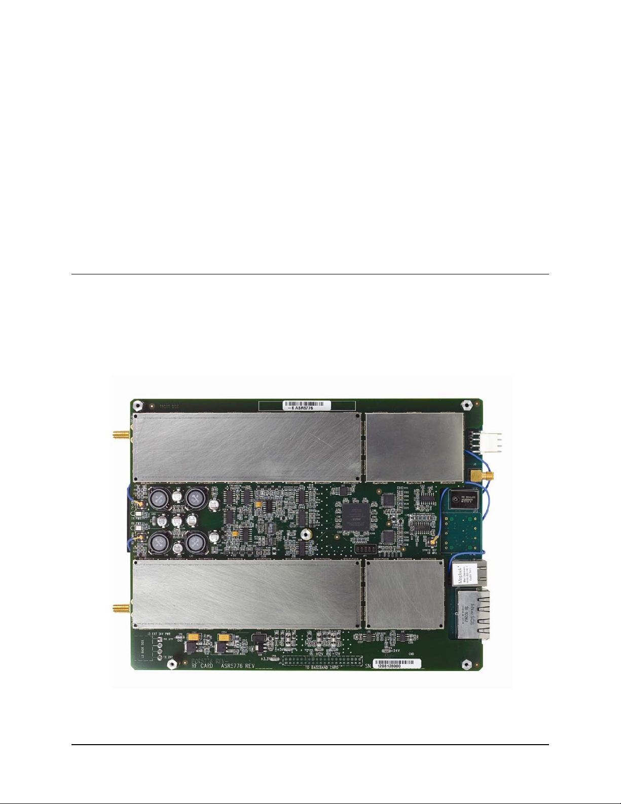
This chapter provides an overview of the DMD1050 Satellite Board Modem, which is designed
for satellite IP, telecom, video and internet applications.
1.1 Overview
• Duplex L-Band modem
• MIL-STD-188-165A standards
• IDR, IBS and DVB
• Data rates up to 20 Mbps
Chapter 1. Introduction
Figure 1-1. DMD1050 Satellite Board Modem (Top Vi ew)
MN-DMD1050 1–1
Revision 9
Page 20

DMD1050 Satellite Modem Board Introduction
The DMD1050's impressive remote accessibility rivals all others in the field. Remote control via
RLLP (Radyne Link Level Protocol), Ethernet 10 Base-T SNMP and Web Browser includes
control of all the modem's features plus so f tware maintenance. The unit presents monitor and
control functions on the screen.
Additional options and configuration (such as Monitor and Control (M&C) Functions) can be
activated in seconds via the Web Browser.
Compatibility with current modems, such as the DMD2050, DMD50, DMD20 and the DISA
certified MIL-188-165 compliant DMD15L are maintained for seamless substitution and addition
to existing systems.
This unit offers built in Standard Inter f aces that are selectable from MIL-188-114A and a Dual
Port Ethernet Bridge.
1.2 DMD1050 Configurations
The DMD1050 can be configured in the following different ways:
• Features and options that are installed when the unit is ordered
• Feature upgrades
• Hardware options that the user can install at their own location
• Options that are installed to a unit that is sent to a comtech service center
1.2.1 Features/Options Installed at Time of Order
Features installed at the time of ordering are the options pre-installed/initialized in the factory
prior to shipment. These can be reviewed f r om the web browser. Refer to Section 4, User
Interfaces for information on how to view these features.
Factory installed options are chassis and board configurations that are introduced during
manufacture.
1.2.2 Feature Upgrades
Feature Upgrades are a simple and quick way of changing the feature set of an installed modem.
Feature upgrades are how most DMD1050 options are implemented. Features may be purchased
at any time by contacting a salesperson. Refer to Section 3 and Appendix D, for information on
how upgrade features.
1.3 Function Accessibility
All functions can be accessed with a terminal or personal computer via a serial link for complete
remote monitoring and control capability.
MN-DMD1050 1–2
Revision 9
Page 21
WARNINGS
inside the DMD105.
CAUTION
Make sure to obey proper ESD practices to avoid damaging the unit.
Chapter 2. Installation
This section provides instructions on unpacking and installation, as well as storage of the unit.
2.1 Installation Requirements
Installation of the DMD1050 Modem Board requires adequate planning by the user to ensure no
damage will occur to the unit. Package design considerations for the modem board include
mounting, temperature limits, adequate ventilation, limited vibration, no exposure to
condensation/ moisture and a stable power source.
Mating connectors are supplied with each unit. A full description of the modems pin outs can be
found in Section 4. Appendix E gives details of the various connectors and mating connectors
supplied.
1. The DMD1050 contains a Lithium Battery. DANGER OF
Before connecting power to the unit, disconnect the transmit output from the
operating ground station equipment. Communication traffic can be disrupted
by connecting power to a unit when the configuration settings are not known
and may be incorrect.
EXPLOSION exists if the battery is incorrectly replaced. Replace only
with the same or equivalent type recommended by the manufacturer.
Dispose of used batteries in accordance with local and national
regulations
2. Make sure to eliminate the potential for Static Discharge that can
damage the Modem Board.
3. There are no user-serviceable parts or configuration sett ings located
MN-DMD1050 2–1
Revision 9
Page 22

DMD1050 Satellite Modem Board Installation
CAUTION
First, make sure to select the DMD1050 Int erf ace Type (MIL-188-114A or
2.2 Unpacking
The DMD1050 Universal Satellite Mod em was carefully packaged to avoid damage an d should
arrive complete with the following items for proper installation:
• DMD1050 Modem Board
• Installation and Operation Manual
2.3 Removal and Assembly
The DMD1050 Modem Unit is shipped fully assembled.
Make sure to obey proper ESD practices to avoid damaging the unit.
Carefully unpack the unit and ensure that all of the above items are in the carton. If the available
Power cable and Data cables can be supplied.
2.4 Installation Considerations
User must consider adequate ventilation when installing the DMD1050 into the final package.
The recommended ambient temperature for the modem board should be between 10° and 35°C,
and held constant for best equipment operation. Ventilated air should be clean and relatively dry.
Modem board must have adequate spacing between other products to avoid cross talk or electrical
shorts. Modems should not be placed immediately above a high-heat or EMF Generator to ensure
the output signal integrity and proper receive operation.
Do not install the DMD1050 in an unprotected outdoor location where there is direct contact with
rain, snow, wind or sun. The only tools required for installing the DMD1050 are five (5)
mounting holes. Caution should be exercised when installing the modem board to ensure the
modem board is not bent, warped or compressed to ensure the unit does not get damaged.
2.5 DMD1050 Initial Configuration Check
The DMD1050 is shipped from the factory with preset factory defaults. Upon initial power-up, a
user check should be performed to verify the shipped modem configuration. Refer to Section 4;
User Interfaces, to locate and verify that the following configuration settings are correct:
Ethernet Data Interface) BEFORE you install the mating connectors. Failure
to do this can damage the Data Interface.
MN-DMD1050 2–2
Revision 9
Page 23

DMD1050 Satellite Modem Board Installation
Using the modem’s loopback capabilities with the Ethernet data interface can cause
loopback, the results will not be as desired.
IMPORTANT
Implementing Strap Code 26 can set the following modem configuration.
the strap code.
IMPORTANT
2.5.1 Standard DMD1050 Factory C onfi guration Settings
Refer to Table 4-4 for an explanation and tabular listing of available Strap
Codes. The Frequency and Modulator Output Power are set independently of
Modulator:
Data Rate: 2.048 Mbps
Mode: Closed Network
Satellite Framing: None
Scrambler: V.35 (IESS)
Inner FEC: 1/2 Rate Viterbi
Outer FEC: Disabled
Modulation: QPSK
Frequency: 950 MHz
Modulator Output Power: -20 dBm
Demodulator:
Data Rate: 2.048 Mbps
Mode: Closed Network
Satellite Framing: None
Scrambler: V.35 (IESS)
Inner FEC: 1/2 Rate Viterbi
Outer FEC: Disabled
Modulation: QPSK
Frequency: 950 MHz
To lock up the modem, enter ‘IF Loopback Enable’ under the Test Menu, or connect a Loopback
Cable from TX port to RX port.
undesirable network loops. Before you do any data test with an Ethernet interface,
make sure to use two modems connected back-to-back. If you use one modem and a
MN-DMD1050 2–3
Revision 9
Page 24

DMD1050 Satellite Modem Board Installation
IMPORTANT
Make sure that the modem’s input DC power is clean, stable and free of spikes.
and may be incorrect.
2.6 Modulator Chec kout
The following descriptions assume that the DMD1050 is installed in a suitable location with
clean, stable DC power. Make sure that DC spikes are not present during initial power up.
2.6.1 Initial Power-Up
If the input DC power is of poor quality, it will damage the unit .
Before connecting power to the unit, disconnect the transmit output from the
operating ground station equipment. Communication traffic can be disrupted
by connecting power to a unit when the configuration settings are not known
New units are shipped with the transmit carrier set to OFF.
The initial field checkout of the modem can be accomplished from the Web Browser or Terminal
Mode. The Web Browser and Terminal Mod e has the advantage of providing full screen acce ss
to all of the modem’s parameters, but requires a separate terminal or computer running a
Terminal Program. The modem is configured with the Web Browser enabled.
2.6.2 M&C Web Browser Setup
The Ethernet M&C Interface requires a standard RJ45 Male connector. The Ethernet Interface is
shipped from the factory in an addressable defaulted condition that allows the user to access the
unit. This condition is identified as IP TEST MODE. .
Boot Modes: IPTEST
IP Address Mask: 255.255.255.000
Modem IP Address: 192.168.0.238
Server IP Address: 192.168.000.101
Router IP Address: 192.168.000.102
Refer to section C & D for proper setup of the Ethernet M&C Interface.
Connect an Ethernet cable between the unit and a computer that has web browser capability.
Access the browser and enter the default web address for the unit.
Refer to Section 4
Refer to Appendix C
Setup.
for a complete description of the GUI Interface operation and parameters.
and Appendix D for proper setup of the TCP-IP interface and Web Browser
MN-DMD1050 2–4
Revision 9
Page 25

DMD1050 Satellite Modem Board Installation
Web Browser and Terminal Interfaces Reset
See Section 3 for more information.
IMPORTANT
2.6.3 M&C Terminal Setup
The initial field checkout of the modem can also be accomplished from the Terminal Mode. The
Terminal Mode has the advantage of providing full screen access to the modem’s para met er s, but
requires a separate terminal or computer running a Terminal Program such as Hyp er-ter minal an d
connection to the applicable pins on the M&C connector J1. The recommended terminal setup is
as follows (These settings can be changed via the Web Browser):
Emulation Type: VT-100
Baud Rate: 19.2 K
Data Bits: 8
Parity: No Parity (Fixed)
If you cannot access the Web Browser or Terminal interface, reset the
interface defaults. To reset the interface defa ults, use the shorting plug
(CNRSHUNT). Obey these steps:
1. Make sure the electrical power to the unit is disconnected.
2. Find the JP5 and JP6 connectors.
3. Find pins 1 and 2 on the JP5 and JP6 connectors.
4. Install the CNRSHUNT shorting plug on pins 1 and 2 of JP5 and pins
1 and 2 of JP6.
5. Connect the electrical power to the unit.
6. This will reset the interface defaults.
MN-DMD1050 2–5
Revision 9
Page 26

DMD1050 Satellite Modem Board Installation
2.7 Storage
It is recommended that the unit be stored in its original sealed packing. The unit should be stored
in a dry location where the temperature is stable, away from direct contact with rain, snow, wind,
sun, or anything that may cause damage.
MN-DMD1050 2–6
Revision 9
Page 27
L - Band
IF
Card
Digital
Baseband
Card
(
Interface
&
Turbo
)
Cable
Chapter 3. Theory of Operation
3.1 DMD1050 Hardware
The DMD1050 is based on a two printed circuit card design. The standard configuration consists
of an L-Band Assembly and a Digital Baseband Assembly. This configuration includes built in
Data interfaces and a number of different software upgrade options. A block diagram of the
DMD1050E is shown in Figure 3-1.
Figure 3-1. DMD1050 Block Diagram
MN-DMD1050 3–1
Revision 9
Page 28
DMD1050 Satellite Modem Board Theory of Operation
Quadrature
Demodulator
IF Board Connector (40-Pin Header)
Demodulator I
Demodulator I Inv.
Demodulator Q
Demodulator Q Inv.
AGC
L-Band
Synthesizer
PDA
Analog Q Inv.
Analog I Inv.
L-Band
Synthesizer
Quadrature
Modulator
Analog Q
Analog I
LPF
LPF
Switch
RxLB
TxLB
Coupler
DCSA
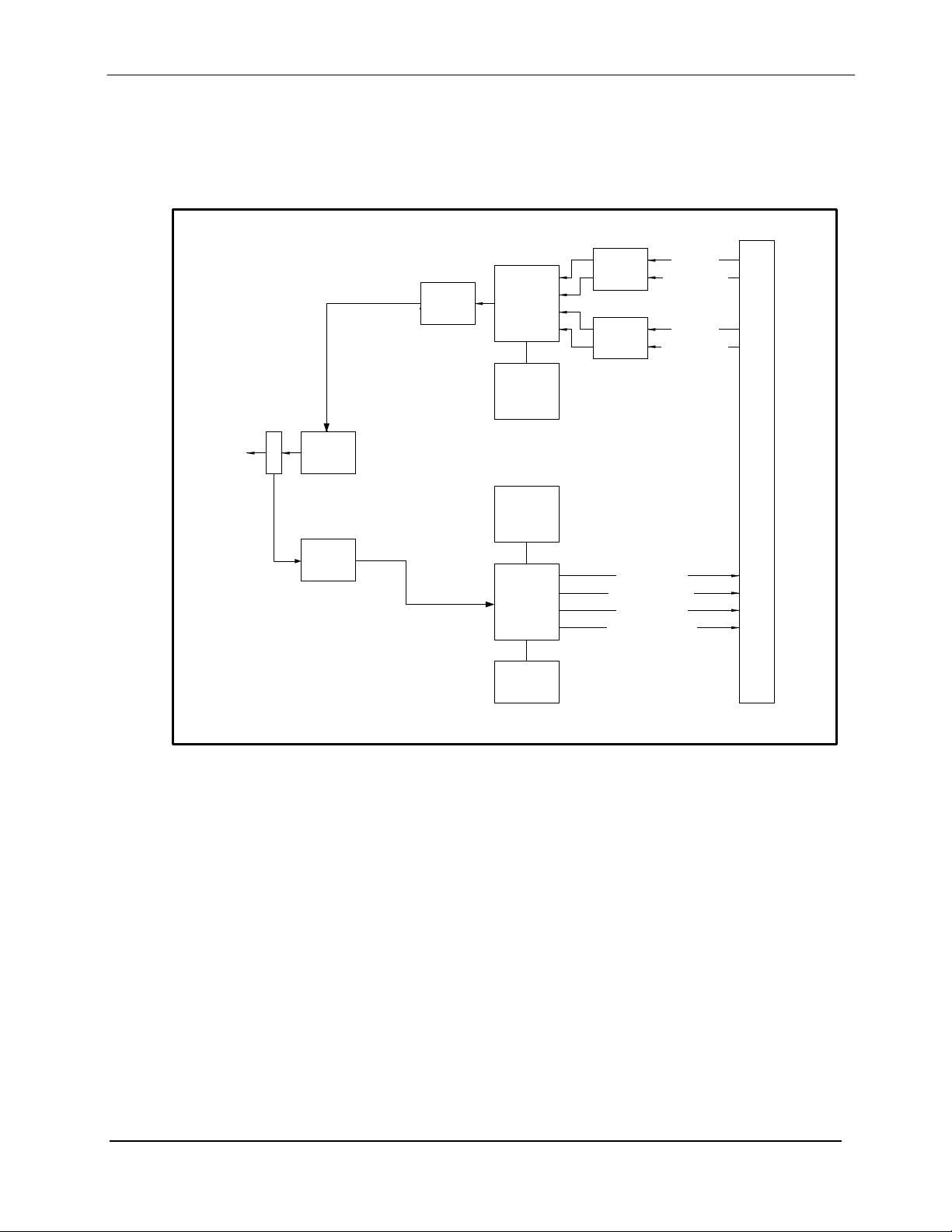
3.1.1 DMD1050 L-Band Printed Circuit Card
The L-Band/IF Printed Circuit Card consists of an analog modulation function, an analog
complex down conversion, and two wide-band digital synthesizers. The block diagram of the LBand Assembly is shown in Figure 3-2.
Figure 3-2. L-Band Assembly
In the modulator, analog in-phase (I) and quadrature (Q) signals are generated on the Digital
Baseband Printed Circuit Card, routed to the L-Band Printed Circuit Card, and modulated at the
desired frequency. The L-Band modulated signal is then passed through a microprocessor
controlled variable attenuator providing gain control of the output signal.
In the complex downconverter, the signal for demodulation is amplified and sent through a
variable wideband attenuator for AGC. Th e gain-controlled signal is then passed through a
complex downconverter to a low IF.
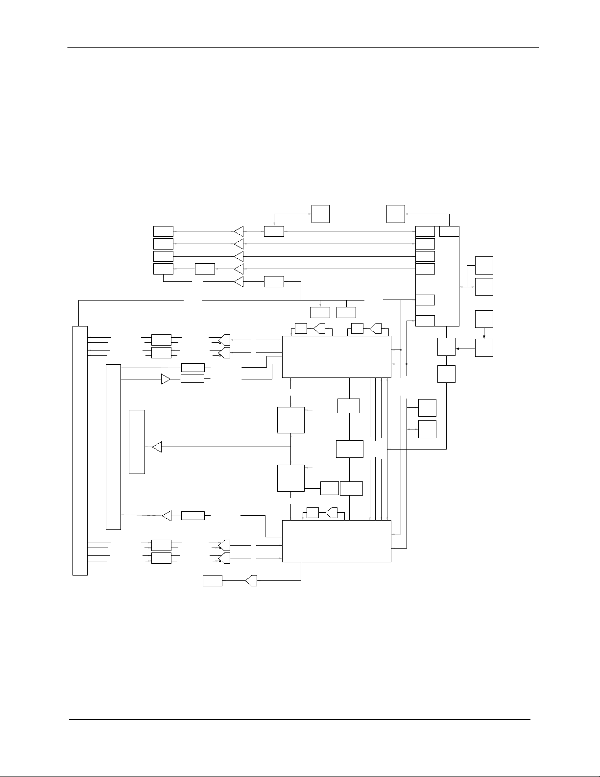
3.1.2 DMD1050 Baseband Processing Printed Circuit Card
The advent of million-plus gate count FPGAs, advanced logic syn thesis tools, and DSPs
providing hundreds of MIPs enabled the design of a software configurable mod em. Large, fast
FPGAs now provide designers with what is essentially an on the fly programmable ASIC . High
speed, complex digital logic functions that previously could only be implemented in dedicated
integrated circuits are now download ed from a micro-controller through a serial or peripheral
interface. When a new digital logic function is needed, a new configuration file is loaded into the
MN-DMD1050 3–2
Revision 9
Page 29
DMD1050 Satellite Modem Board Theory of Operation
Battery
Xtal
uProcessor
PCMCIA
Controller
SCC2
SMC2
SCC3
GPIO
uProc
Bus
SPI
40
MHz
x2
Compact
Flash
Demodulator
FPGA
SDRAM
2 x
Boot
Flash
8 Mbx8
256 Mbx16
25 MHz
Xtal
Ethernet
PHY
Relays
Fault
(DB9)
RLLP
Terminal
Ethernet
DAC
AGC
Modulator
FPGA
SCT/SCTE
Rx SAT
Loopback
80 MHz
uProc Bus
SPI Bus
I/Q
TP
2 x
r2r
Q
I
ADC
ADC
Analog I Filter
Analog I Inv Filter
Analog Q Inv Filter
Analog Q Filter
Alias
Filter
Alias
Filter
Analog I Unfilter
Analog I Inv Unfilter
Analog Q Unfilter
Analog Q Inv Unfilter
DMD1050 IF Board Connector (40-Pin Header)
I
Q
Analog Q Inv Unfilter
Analog Q Unfilter
Analog I Inv Unfilter
Analog I Unfilter
Analog I Filter
Analog I Inv Filter
Analog Q Filter
Analog Q Inv Filter
Alias
Filter
Alias
Filter
ADC
ADC
DB-25 Sync Data (RS-422, MIL-STD-188-114A) & Ethernet 10Base-T
TPC Codec
ADC
Serial
EEPROM
SPI Bus
SPI Bus
Terrestrial Data
LPF
DAC
Tx
Clk
SCT
LPF
R2R
SCT
R2R
LPF
Insert DSP
Mem Space DMA
Drop DSP
Mem Space DMA
Buf
SRAM
40 MHz
40 MHz
Async (DB-9)
Buffers
Terrestrial Data
Buffers
Terrestrial Data
Buffers
10 Mhz
OCXO
PLL
Buffers
Buffers
FPGA. There is no limit to the number of digital logic configurations available to the FPGA,
aside from the amount of Flash memory availabl e to the system microprocessor for storage of
configuration files.
The DMD1050 Baseband Processing Printed Circuit Card provides a flexible architecture that
allows many different modes of terrestrial and satellite framing, various FEC options, digital
voice processing, and several different modulation/demodulation formats. Also included on the
Baseband Printed Circuit Card is a MIL-188-114A/RS-422 synchronous interfaces and a two port
10/100 Ethernet Bridge interface.
A block diagram of the Baseband Processing Card is shown in Figure 3-3.
Figure 3-3. DMD1050 Baseband Processing Card B lock Diagram
MN-DMD1050 3–3
Revision 9
Page 30

DMD1050 Satellite Modem Board Theory of Operation
The DMD1050 supports IBS & IDR compatible framing modes. Since
supported in a Closed network Mode.
IMPORTANT
The Baseband Printed Circuit Card also contains the Monitor and Control (M&C) Circuitry
responsible for:
Programmable part setup and initiali zation
Continuous control and adjustment of some functions
Calibration
Monitoring fault status
Calculating and displaying measurements
Calculations
User monitor and control interface including front panel and remote
Unit’s configuration and feature set
The M&C System is based on a powerful microprocessor with a large amount of Flash memory.
Several bus architectures are used to interconnect the M&C to all components of the DMD1050.
Communication to the outside world is done via connections to the remote port, terminal port,
Ethernet port, and alarm ports. The M&C runs off software programmed into its Flash memory.
The memory can be reprogrammed via the E thernet port to facilitate changes in software.
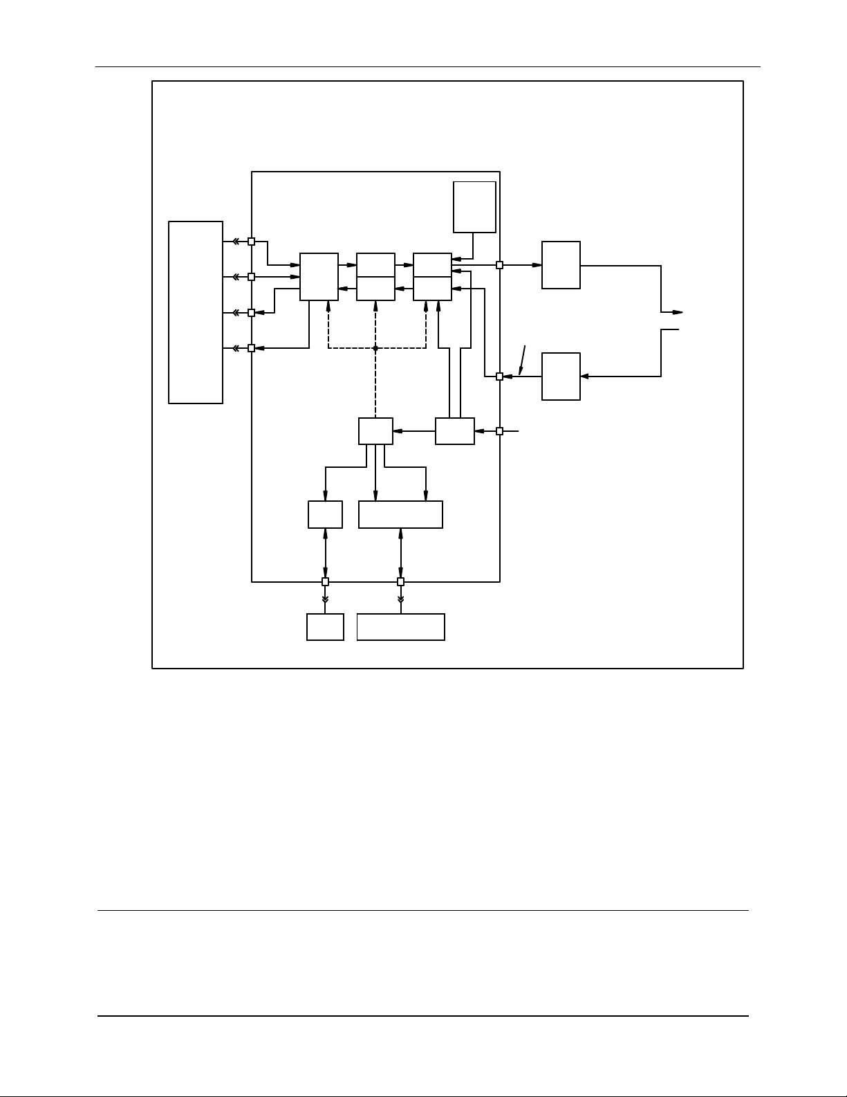
3.2 DMD1050 Functional Block Diagram
Figure 3-4 represents the DMD1050 Functional Blocks. The modem is shown in a typical
application with customer data, Tx/Rx RF equipment and an antenna.
3.2.1 Baseband Proces si ng
The Baseband Processor performs all of the functions required for an IBS/IDR Framing Unit, a
Reed-Solomon Codec. In addition, the Baseband Processing Section provides for transmit clock
selection and rate adaptation as well as a rate adapter and Plesiochronous/Dopp ler (PD) Buffer in
the receive direction. A multiplexer is also provided for the SCT Clock Source for Loop Timing
Applications. The transmit and receive paths may be configured independently under processor
control.
the modem does not have all supporting interfaces as stipulated by
IESS308/309, it is not 100% compliant. IBS and IDR framing modes are
3.2.2 Tx Baseband Proces si ng
The Tx Data and Clock enters the Baseband Pr ocessor, passes through a Rate Adapting F I FO and
enters the Framer Processor. In Closed -Net Mode, the data passes through the framer unaltered.
In IDR & IBS framining enabled, it adds the appropriate framing as defined in IESS-308 and
309. The data is then sent to the Reed-Solomon Encoder.
The Reed-Solomon Encoder, encodes the data into Reed-Solomon Blocks. The blocks are then
interleaved and synchronized to the frame pattern as defined by the selected specification (IESS308, IESS-309, DVB, etc.). After Reed-Solomon Encoding, the composite data and clock are
applied to the BB Loopback Circuit.
MN-DMD1050 3–4
Revision 9
Page 31
DMD1050 Satellite Modem Board Theory of Operation
Sync
Data
I/O
Collector
Terrestrial
Phy
Rx DSP
Tx DSP
Digital
Baseband
Processor
M&C
DEMOD
FPGA
Universal
Modem
MOD
FPGA
Terminal
Remote
Port
Power
Regulator
2 x 10
1 x 10
-6
8
Reference
Ref. (Opt.)
Remote Serial Interfaces
DMD1050
Universal Satellite
Modem
Tx
RF
Equipment
Rx
RF
Equipment
IF Input
950-2050 MHz
IF Output
950-2050 MHz
0 to -25 dBm
+24 VDC
Asynchronous
Overhead
LAN
10 Base-T
Ethernet
Ethernet
Data
Interface
Antenna
Open
Faults
Figure 3-4. DMD1050 Universal Satellite Modem Functional Block Diagram
3.2.3 Rx Baseband Proces si ng
The Receive Processor performs the inverse function of the Tx Processor. Data received from the
satellite passes through the BB Loopback Circuit to the Reed-Solomon Decoder to the Deframer.
The Deframer acquires the IBS/IDR/DVB frame, synchronizes the Reed-Solomon Decoder and
extracts the received data and over head from the frame structure, placing the data in to the PD
Buffer, sending the overhead data to the UIM. The data is extracted from the buffer and is sent to
the UIM. Backward Alarm indications are sent to the M&C Subsystem.
3.3 Monitor & Control (M&C)
The modems M&C system is connected to most of the circuitry on any board contained in the
modem. These connections provide status on the working condition of the circuitry as well as
providing the data required for the various measurements the modem provides. The M&C
MN-DMD1050 3–5
Revision 9
Page 32

DMD1050 Satellite Modem Board Theory of Operation
processes this information and generates status indications as well as alarms when necessary.
Detailed status information is available via the modems various user interfaces including the
remote and terminal ports. An external summary fault is available on the RS422 Data int er f ace
The M&C contains a high-performance microprocessor and is responsible for overall command
and control of modem functions. The M&C is constantly monitoring all subsystems of the
modem by performing a periodic poll routine and configures the modem by responding to
commands input to the system. During each poll cycle, the status of each of the sub systems is
collected and reported to each of the external ports. Performance statistics such as Eb/No, buffer
fill %, etc. are compiled. If faults are detected, the M&C will take appropriate actions to
minimize the effect of such faults on the system (refer to the Fault Matrices in Section 6).
The DMD1050 supports the following M&C protocols: These are:
Terminal Interface (Section 3.3.1)
Remote Port Interface (Section 3.4)
Web Browser (Section 3.5)
M&C Default/Reset Plug Settings (Sections 3.6 and 4.4.4.1)
SNMP (Simple Network Management Protocol (Refer to TM117 Remote Protocol Manual)
3.3.1 Terminal Port/ES-ES Communications (J1)
J1 functions as the Modem Remote Port, Terminal Port or ES-ES Communications. For
Terminal port application, it supports an asynchronous control protocol. It may be configured to
support either RS-232 or RS-485 signal levels. This port is intended for use in computer-based
remote M&C. All functions of the modem may be monitored and controlled from this port via a
common terminal connected to the Terminal Port. This function is front panel selectab le.
This port is also dedicated for ES-ES Communications. The port may be configured for a number
of communications protocols. Overhead data to/from the UIM is routed to/from the
framer/deframer. This port may be configured to support either RS-232 or RS-485 signal levels.
The baud rate and protocol can be selecte d from the Web Browser.
3.3.2 Terminal Mode Control
The DMD1050 Terminal Mode Control allows the use of an external terminal or computer to
monitor and control the modem from a full screen interactive presentation operated by the modem
itself. No external software is required other than VT-100 Terminal Emulation Software (e.g.
“Procomm” for a computer when used as a terminal. The Control Port is normally used as an
RS–232 Connection to the terminal device. The RS-232 operating parameters can be set using
the modem Front Panel and stored in Non-volatile memory for future use (refer to the Remote
Protocol Manual TM117 for setup and terminal screens).
3.3.3 Modem Terminal Mode Control
The modem can be interactively monitored and controlled in the Terminal Mode, with a full
screen presentation of current settings and status. Programming is accomplished by selecting the
item to be modified and pressing the terminal key of the option number. For example, to change
the transmit data rate, enter ‘33’ at the terminal. The modem will respond by presenting the
options available and requesting input. Two types of input may be requested. If the input is
multiple choice, the desired choice is selected by pressing the ‘Space’ key. When the desired
MN-DMD1050 3–6
Revision 9
Page 33

DMD1050 Satellite Modem Board Theory of Operation
IMPORTANT
option is displayed, press the ‘Enter’ key to select that option. The other possible input type
requires a numerical input (such as entering a frequency or data rate.
This type of input is followed by pressing the ‘Enter’ or carriage return key. An input can be
aborted at any time by pressing the ‘ESC’ key. Invalid input keys cause an error message to be
displayed on the terminal.
The Terminal Control Mode supports serial baud rates of 150, 300, 1200, 2400, 4800, 9600,
19200, and 38400. The connection must be set for 8 data bits, 1 stop bit and no parity (8,N,1).
Three terminal emulations are suppor ted: VT-100, WYSE 50, and ADDS-VP.
“$” is used for setting the screen when the terminal is used for the first time the non-volatile
memory is reset.
3.3.4 Modem Setup for Terminal Mode
Terminal Mode Communications and Protocol is set from the Web Browser by setting the
“Control Mode” Parameter to “Terminal”, and then setting the “Modem Port”, “Term Baud” and
“Emulation” Parameters as desired. Then a terminal is connected to J1connector. All operating
software for the Terminal Mode is contained within the DMD1050 Modem Internal Control
Software.
A “break” signal on the communications line, pressing “ESC” on the terminal or Power On o f the
modem will initiate full screen terminal mode printing and redraw the full screen. The Terminal
Mode displays the present status of all user parameters controlled and read by the processor, and
offers a menu allowing change to any controlled parameter.
The Terminal Mode uses eight “Screens,” each of which have the basic contents of the three
modem monitor and control areas as set in the Front Panel matrix columns. This screen is used
for setting the parameters of the Modulator, Demodulator, Event, Alarm, Latched Alarm, and
Interface Areas.
The Terminal Control Mode is menu-driven and the allowable values for each item number will
be shown. To change an item, type in its number followed by <ENTER>. If the parameter to be
changed requires a numeric value, enter th e number followed by <ENTER> If the parameter i s
non-numeric, press <SPACE> to cycle through the list of available entries.
Items that do not have ID numbers are Status only and cannot be
changed.
3.3.5 Connecting the T erminal
1. Connect the computer to the DMD1050 Remote Connector (J1) on the board using the
RS-232 Cable.
2. Enable the termi nal by selecting Terminal Mode under the Web Browser
3. Verify that your emulation software is set to the following:
8 data bits
no parity
MN-DMD1050 3–7
Revision 9
Page 34

DMD1050 Satellite Modem Board Theory of Operation
IMPORTANT
IMPORTANT
1 stop bit
3.3.6 Terminal Screens
Refer to the Remote Protocol Manual (TM117) for the terminal screens.
3.4 Modem Remote Communications (RLLP)
The Remote Port located on J1 allows for control and monitoring of parameters and functions via
an RS-232 Serial Interface, or RS-485 for RLLP Protocol. ‘Equipment Remote Mode’ setup can
be entered from the Web Browser interface under the “System” menu. This requires the u ser to
first set the Remote Port Control to “Remote” then set the Multidrop Address as needed followed
by setting the Remote Interface to RS232 or RS485.
Control and status messages are conveyed between the modem and all subsidiary modems and th e
host computer using packetized message blocks in accordance with a proprietary communications
specification. This communication is handled by the Radyne Link Level Protocol (RLLP), which
serves as a protocol ‘wrapper’ for the RM&C data. Complete information on monitor and control
software is contained in the following sections.
3.4.1 RLLP Protocol Structure
The Communications Specification (COMMSPEC) defines the interaction of computer resident
Monitor and Control Software used in satellite earth station equipment such as modems,
redundancy switches, multiplexers, and other ancillary support gear. Communication is bidirectional, and is normally established on one or more full-duplex 9600-baud multi-drop control
buses that conform to EIA Standard RS-485.
Each piece of earth station equipment on a control bus has a unique physical address, which is
assigned during station setup/configuration or prior to shipment. Valid decimal addresses on one
control bus range from 032 through 255 for a total of up to 224 devices per bus. Address 255 of
each control bus is usually reserved for the M&C computer.
Refer to the Remote Protocol Manual (TM117) for the RLLP Protocol.
3.5 Modem Setup for Ethernet M&C (J10)
This port is dedicated for Ethernet Communications supporting SNMP, FTP and Web Browser.
The port is configured for 10 Base-T communications protocols. The Ethernet M&C Interface
requires a standard RJ45 Male connector. The Ethernet Interface is shipped from the factory in
an addressable “BOOT MODE” state that allows the user to access the unit. This “BOOT
MODE” state is set to “IP TEST”.
MN-DMD1050 3–8
Revision 9
Page 35

DMD1050 Satellite Modem Board Theory of Operation
IMPORTANT
Connect an Ethernet cable between the unit and a computer that has web browser capability.
Access the browser and enter the default web address for the unit. Refer to Section 4
for a
complete description of the GUI Interface operation and parameters. Refer to Appendix C and
Appendix D for proper setup of the TCP-IP interface and Web Browser Setup.
3.6 M&C Default/Reset Plug Settings (JP5 & JP6)
If the user is experiencing difficulty accessing the Web Browser or the Terminal Interface, the
user can reset the interface settings by utilizing the supplied default plug CNRSHUNT. on the
JP5 and JP6 connectors. Refer to Figure 4-5. By installing the default plug onto pins 1 & 2 of
JP5 and JP6 and cycling power, the unit communication parameters will be reset to the following
settings:
TCP-IP BOOT MODE will be set to IP TEST. (Refer to TCP-IP Setup Appendix)
Remote Control Mode will be set to Terminal
Terminal port will be set to RS232
Web Browser Names and Passwords are Reset: (Refer to Web Browser Setup Guide,
Appendix D)
Once default settings have been activated, remove Jumpers.
3.7 Ethernet Data Interface – (J11)
If the Ethernet Data Interface is selected, then the Tx Clock Source will default to SCTE and the
Clock Polarity will default to Normal. Th e Ethernet Bridge Interface makes connecting LAN's via
satellite easy to do. Simply select Ether net as your terrestrial interface and plu g your LAN into
any of the two RJ-45 connectors on the unit. With its multi-port interface, automatic Learning
and Aging, Auto-Crossover, Auto-Polarity, Auto-Negotiation and embedded Quality of Service,
the Enhanced Ethernet Interface offer s true Plug-n-Play connectivity.
The DMD1050 Ethernet Interface maintains backward compatible with the
DMD20/20LBST/DMD50/DMD2050 and the OM20. It Allows for all higher level protocols like
DHCP, UDP, TCP, HTTP, and FTP, etc. to pass transparently. And with it’s line speed learning
capability, traffic is forwarded immediately to the appropriate ports without any unnecessary
startup delay.
For users who desire more control over their traffic, the Ethernet interface provides additional
QOS controls and new features such as port based priorities, strict priority queuing, and the
ability to operate in a FIFO like mode.
When it comes to performance, the full duplex capability of the standard 10/100 interface allows
it to pass up to 20 Mbps in each direction over the satellite.
The DMD1050 supports Radyne HDLC an d Comtech HDLC modes,
offering compatibility with the SLM5650A Bridge Interface.
MN-DMD1050 3–9
Revision 9
Page 36

DMD1050 Satellite Modem Board Theory of Operation
3.7.1.1 Configuring the Modem to use the Ethernet Data Interface
When the optional Ethernet Data Interface Card is selected, all of the Ethernet related menus can
be used to control the interface as follows:
Setup the TX Interface Menu to: (refer to Section 7.3.4.3 Figure 7-16 for Interface/TX Setup)
Set the Terrestrial Interface to Ethernet.
Set the Ethernet Flow Control as desired
Set the Ethernet Daisy Chain as desired
Set the Ethernet QOS Type as desired
Set the Ethernet QOS Queue as desired
Tx Clock is set to SCTE.
Set the Tx Clock Polarity to Normal.
Setup the RX Interface Setup Menu to: (refer to Section 7.3.4.3 Figure 7-17 for Interface/RX
Setup)
Set the Terrestrial Interface to Ethernet.
Set the Buffer Size to Zero.
Buffer Clock is set to Rx Sat.
Set the Buffer Clock Polarity to Normal.
3.7.1.2 Ethernet Flow Control
When disabled, if a packet is received for transmission and no packet buffer space is available,
the incoming packet is discarded.
When enabled, flow control is used to throttle the transmission station in order to avoid
overrunning the transmit buffers, which would in turn cause packets to be dropped. The
throttling mechanism used depends upon the interface and whether it is half-duplex or full
duplex.
3.7.1.3 Half-Duplex Flow Control
In half-duplex mode, the unit uses industry standard backpressure to support flow control as
follows:
When available buffer space is almost gone, the modem will force a collision on the input port
when it senses an incoming packet. Th is collision will cause the transmitting station to back off
and retry the transmission.
The interface will stop forcing collisions as soon as free buffer space becomes av ailable.
3.7.1.4 Full-Duplex Flow Control
In full-duplex mode, the interface implements IEEE 8802.3x flow control as follows:
When available buffer space is almost gone, the unit sends out a pause frame with the maximum
pause time to stop the remote nodes from transmitting.
MN-DMD1050 3–10
Revision 9
Page 37

DMD1050 Satellite Modem Board Theory of Operation
The interface sends out another pause frame with the pause time set to zero as soon as free buffer
space becomes available.
3.7.1.5 Ethernet Daisy Chain
When disabled, Port 2 on the Ethernet Data Interface operates normally. Data received on Port 2
that is not addressed to other equipment o n the LAN side, is transmitted over the satellite.
When Port 2 is selected for Daisy Chain, any data received on Port 2 is forwarded to of the other
LAN side ports (Ports 1) and is not transmitted o ver the satellite. This is extremely useful in a
point-to -multipoint configuration as illustrated in Figure 3-5.
3.7.1.6 Ethernet QOS Type
When Normal QOS is selected, the interface determines a packets priority based on the
following:
IEEE 803.3ac Tag when present
IPv4 Type of Service / Differentiated Services Field
Ipv6 T raffic Class
When Port Based QOS is selected, the interface determines the priority of a packed based upon
the port on which it arrived.
Port 1 (JS1) has the highest priority
Port 2 (JS2) has the second highest priority
3.7.1.7 Ethernet QOS Queue
When Fair Weighted queuing is selected, the interface transmits packets at a rate of 8, 4, 2, and 1
from the highest priority queue to the lowest respectively. With fair weighted queuing, all queues
with data in them are guaranteed to receive some bandwidth.
When Strict Priority is selected, the interface transmits packets from the highest priority queue
until it is empty. It then begins transmitting data from the next highest priority queue. If higher
priority data arrives, the interface finishes the current packet and then goes back to transmitting
packets from the higher priority queue until it is again empty. Care must be taken when sel ecting
Strict Priority, as it is entirely possible for the lower priority queues to be stalled indefinitely.
MN-DMD1050 3–11
Revision 9
Page 38

DMD1050 Satellite Modem Board Theory of Operation
3.7.1.8 Setting Up The DMD1050 Ethernet Bridge To Operate Like A FIFO
In certain circumstances, it may be desir able to have the Ethernet interface operate i n a FIFO like
manner with no reordering of packets. This can be established by using a single port on the
Ethernet interface and setting the Ethernet QOS Type to Port Based and the Ethernet QOS Queue
to Strict Priority. When Setup and used in this manner, the packets will be transmitted in the exact
order in which they are received.
Figure 3-5. Point-to-Multipoint with Daisy Chaining
MN-DMD1050 3–12
Revision 9
Page 39

DMD1050 Satellite Modem Board Theory of Operation
3.7.1.9 Packet Statistics
The following statistics are available under the Monitor Menu when the Ethernet Data Interface is
selected.
Total Packets: This Counter displays the total number of Ethernet packets received from the
satellite.
Error Packets: This counter displays the total number of Ethernet packets received from the
satellite that had errors.
Packet Error Rate: This displays the Ethernet Packet Error Rate (PER) from the satellite.
Packet Statistics Reset: Allows the user to r eset the Ethernet Total Packets and Ethernet Error
Count by pressing <Enter>.
Link Status: The following status is available under the Monitor Menu/Link Status Sub-Menu
when the Ethernet Data Interface is selected:
Port 1 Status: Displays the current status of LAN Port 1.
Port 2 Status: Displays the current status of LAN Port 2.
For each of the above-listed ports, the status may take on one of the following values/meanings.
Down: The link is down.
Unresolved: Unable to agree on connection speed.
10 Mbps Half: Connected at 10 Base-T Half Duplex.
10 Mbps Full: Connected at 10 Base-T Full Duplex.
100 Mbps Half: Connected at 100 Base-T Half Duplex.
100 Mbps Full: Connected at 100 Base-T Full Duplex.
If all LAN Ports are down, a Tx Data Activity Minor Alarm will be generated.
If the WAN Port is down, a Tx and Rx Ethernet WAN Major Alarm will be generated.
3.8 Internal Clock
The time and date is kept in order to ‘time-tag’ system events. User can change the time and date
via the Web Browser.
MN-DMD1050 3–13
Revision 9
Page 40

DMD1050 Satellite Modem Board Theory of Operation
Usage of the modems loopback capabilities in conjunction with the
IMPORTANT
3.9 Loopback Features (Terrestrial & IF)
The modem provides for a number of different loopbacks. The Loopback supported are:
IF Loopback – Tx IF port is looped back to the Rx IF port
TX Terrestr ial Loopback - Tx Data port is looped back to the Rx Data port after the
interface driver/receiver. (prior to the framing unit)
TX Baseband Loopback - Tx Data port is looped back to the Rx Data port after the
interface driver/receiver. (after the framing unit)
RX Terrestrial Loopback - Receive Data from the sat ellite is looped back for retransmission
to the satellite, providing a far end loopback. (prior to the framing unit)
RX Baseband Loopback - Receive Data from the satellite i s looped back for retransmission
to the satellite, providing a far end loopback. (after to framing unit)
TX/RX Terrestrial Loopback - provides both Terrestrial loopbacks simultaneously
TX/RX Baseband Loopback - provides both Baseband loopbacks simultaneously
Refer to Figure 3-6 through Figure 3-8 for loopback functional block diagrams.
Ethernet data interface can produce und esirable network loops. In order
to run any type of data test with an Ethernet interface you must utilize
two modems connected back to back. Simply using one modem and a
loopback will not produce the desired results.
MN-DMD1050 3–14
Revision 9
Page 41

DMD1050 Satellite Modem Board Theory of Operation
Figure 3-6. Loopback Functional Block Diagram
MN-DMD1050 3–15
Revision 9
Page 42

DMD1050 Satellite Modem Board Theory of Operation
Figure 3-7. Loopback Functional Block Diagram
Figure 3-8. Loopback Functional Block Diagram
MN-DMD1050 3–16
Revision 9
Page 43

DMD1050 Satellite Modem Board Theory of Operation
SD
TT
Tx CLK
SRC
High Stability
Oscillator
ST
CLOCK &
DATA
EXT REF
EXTERNAL
INTERNAL
SCT CLK
SRC
REF FREQ
SRC
SCT
SCTE
TRANSMIT
RECEIVE
CLOCK & DATA
RECOVERY
SCT
SCTE
RX SAT
RT
RD
SCR
BUFFER CLK
SRC
DMD1050 CLOCKING AND POLARITY
MODULATION
HIGH STABILITY
DEMODULATION
CLK POL
DATA POLARITY
NORMAL
INVERTED
AUTO
INV. TERR&BASE
INVERT NONE
INV. BASEBAND
INV. TERR DATA
DATA POLARITY
BUFFER CLK POL
NORMAL
INVERTED
INV. TERR&BASE
INVERT NONE
INV. BASEBAND
INV. TERR DATA
3.10 DM D10 50 Cl oc ki ng Opt io ns
The DMD1050 supports a number of different clocking options that can be recovered from the
satellite or the terrestrial links. The v ar ious clocking options allow users to determine which
clock will best fit their applications. Figure 3-9 gives an overview on how the modem processes
the various clocks for the Tx Clock source and the Rx Buffer Clock source. Tx and Rx Clocks
may be independently locked.
Figure 3-9. Clocking and Polarity Diagram
3.10.1 TX Clock Options
TX clock options can be recovered from the t er r estrial interface, satellite interface or internally
generated. The allows users to select SCTE Clock (Terrestrial) or the SCT internal clock. The
MN-DMD1050 3–17
Revision 9
modem also allows user to recover the SCT Clock from the satellite (SCR) or from the modem
internally. The modem allows users to select clock polarity. The Tx clock selections available
are:
Page 44

DMD1050 Satellite Modem Board Theory of Operation
The following paragraphs define the types of clocking options available to the user at the Front
Panel.
SCT (Internal Oscillator)
SCTE (External Tx Terrestrial Clock)
Rx Satellite Clock
3.10.1.1 SCTE: Serial Clock Transmit External
The SCTE clock is the Transmit Terrestrial Clock associated with the data interface. SCTE is an
external clock received from the terrestrial equipment and the modem utilizes the ter r estrial clock
to lock the internal clock.
In Figure 3-9, the Transmit Terrestrial Data enters the modem and is clocked into a deter FIFO.
Data is clocked out of the FIFO by the Modulator Clock. The Modulator Clock and PhaseLocked Loop (PLL), in conjunction with the Dejitter FIFO, which reduces the input jitter. Jitter
reduction exceeds the jitter transfer specified in CCITT G.821.
SCTE is sometimes referred to as Tx Terrestrial Timing or Terminal Timing. Terminal Timing is
reference to the RS422 or MIL 188-114A synchronous interfaces.
3.10.1.2 SCT: Serial Clock Transmit
The SCT clock can be generated internall y or recovered from the satellite. The SCT clock source
can be used as the TX clock source, RX Buffer Clock source and the Terrestrial Terminal
equipment for clocking the transmit data. If the SCT clock is recovered from the satellite, then it
is referred to as SCR. SCR is also referred to as Receive Clock, Satellite Clock, or Receive
Timing (RT).
When SCT clock is configured as Internal, the frequency of the clock is set the same as the
Transmit Terrestrial Clock rate. If SCT clock is configured as SCR, the internal clock is set to the
same rate as the incoming receive satellite clock. SCT is sometimes referred to as Int er nal
Timing or Send Timing (ST). In the event that the satellite clock is lost, the modem will
automatically switch over to the Internal Clock and revert back to SCR when activity is detected.
If SCT is selected, then Terrestrial data that is synchronous to the SCT Clock is required to be
supplied by the modem. It is intended for the terminal equipment to use the SCT as its clock
source. The Autophase Circuit will automatically ensure that the data is clocked correctly into
the modem. Therefore, a return clock is not necessary. The Clock Polarity should be set to Auto.
MN-DMD1050 3–18
Revision 9
Page 45

DMD1050 Satellite Modem Board Theory of Operation
3.10.2 RX Buffer Clock Options
The DMD1050 supports a number of RX Buffer clock options that can be recovered from the
satellite, terrestrial links or internally. The various clocking options allow users to determine
which clock will best fit their applications. Figure 3-9 gives an overview on how the modem
processes the various clocks for the Tx Clock and the Rx Buffer Clock. Tx and Rx Clocks may
be independently locked. The following Buffer clock selections are available on the DMD1050:
SCTE (External Tx Terrestrial Clock)
SCT (Internal Oscillator)
Rx Satellite Clock
The DMD1050 handles RX Buffer clock select ions based on source priority levels. Refer t o
Appendix D “Web Browser Setup”. The user assigns priorities to the clock sources based on
source selections. Source 1 has the highest priority and Source 3 has the lowest prio r ity. If a
fallback clock is selected and activity is lost at the highest priority source, the modem will fall
back to the next highest priority clock with activity. When activity resumes on a higher priority
source, the modem resumes using the higher priority source
Clock Source
RX SAT 1 of 3
SCTE 2 of 3
SCT 3 of 3
Priority
3.10.3 RX SAT Clock
The RX Sat clock is recovered from the satellite that is received from the distant end. I f selected
the Buffer Clock is lock to the RX sat clock .
3.10.4 SCTE: Serial Clock Transmit External
When SCTE is selected as the Rx Buffer clock, the modem receives the clock from the Transmit
Terrestrial interface.
3.10.5 SCT: Serial Clock Transmit
If SCT clock is selected as the RX Buffer clock source, then it should be configured for internal.
SCT is sometimes referred to as Internal Timing or Send Timing (ST).
3.10.5.1 External Reference: J8 SMA Female
This is not actually a clock, but does have some clocking implications. When the external
reference is used, the master oscillator within the DMD1050 is locked to the external r ef er ence,
and the internal accuracy and stability of the DMD1050 assumes that of the External Reference.
Therefore, not only are the transmit frequencies of the DMD1050 locked to the external
reference, but the modem’s internal SCT Oscillator is locked to the external reference as well.
MN-DMD1050 3–19
Revision 9
Page 46

DMD1050 Satellite Modem Board Theory of Operation
IMPORTANT
3.11 Ethernet Data Interface
The modem supports dual port 10/100 Base T Interface. When selected, the Tx Clock Source
will default to SCTE and the Clock Polarity will default to Normal. In addition, the Buffer Clock
will default to RxSat and the Buffer Clock Polarity will default to Normal. Refer to Appendix C
for interface set up and supporting features.
3.12 Reed-Solomon Codec
Refer to Figure 3-10, Figure 3-11 and Table 3-1.
Utilizing a Reed-Solomon (R-S) Outer Codec concatenated with a Convolutional Inner Codec is
an effective way to produce very low error rates even for poor signal-to-noise ratios while
requiring only a small increase in transmission bandwidth. Typically, concatenating an R-S
Codec requires an increase in transmission bandwidth of only 9 – 12% while producing a greater
than 2 dB improvement in E
encoder which adds 2t = (N – K) check bytes to produce an N byte R-S block. The R-S decoder
can then correct up to “t” erred bytes in the block.
. R-S is a block Codec where K data bytes are fed into the
b/No
3.12.1 Reed-Solomon Operation in the DMD1050
When the Reed-Solomon Codec is enabled, data is fed to the R-S Encoding Section of the
DMD1050 where it is scrambled, formed into blocks, R-S encoded, and interleaved. Unique
words are added so that the blocks can b e r ef ormed in the Receiving Modem (Refer to Figure
3-10 and Figure 3-11). Data is then sent to the modulator where it is convolutionally encoded,
modulated and transmitted to the satellite.
When the signal is received and demodulated by the Receiving Modem, it is fed to a Viterbi
Decoder for the first layer of error correction. After error correction is performed by the Viterbi
Decoder, the unique words are located and the data is deinterleaved and reformed into blocks.
The R-S Decoder then corrects the leftover errors in each block. The data is then descrambled
and output from the R-S Section.
3.12.2 Reed-Solomon Code Rate
The Standard R-S Code Rate is defined by (N, K) where N is the total R-S block size in bytes data + check bytes - and K is the number of data bytes input into the R-S Encoder. The
transmission rate expansion required by the R-S Codec is then defined by N/K. In Closed Net
Mode, the DMD1050 allows the following N and K setting: (126, 112), (219, 201), (194, 178),
(225, 205). Table 3-1 reflects IBS/IDR compliant modes.
Custom Reed Solomon rate are available as an option.
MN-DMD1050 3–20
Revision 9
Page 47

DMD1050 Satellite Modem Board Theory of Operation
Type of
Data Rate
R-S Code
Bandwidth
[ (n/k) -1 ]
Interleaving
Maximum
Delay (ms)
Small IDR
64
1536
(126, 112, 7)
(126, 112, 7)
0.125
0.125
4
4
115
5
IDR
1544
(225, 205,10)
0.0976
4
9
8PSK
1544
8448
(219, 201, 9)
(219, 201, 9)
0.0896
0.0896
8
8
18
3
DVB
All
(204, 188, 8)
0.0851
12
-
1. n = code length, k = information symbols and t = symbol error correcting capability.
2. Design objective.
3.12.3 Interleaving
The DMD1050 allows for interleaving depths of 4 or 8 R-S Blocks so that burst errors are spread
over 4 or 8 R-S blocks to enhance the error correction of the R-S Codec. In Closed Network
Mode, manually set the interleaver depth to 4 or 8. In DVB Network Mode, the DMD1050 sets
the interleaver depth to 12 automatically.
Figure 3-10. Reed-Solomon Encoder Functional Block Diagram
Service
(With 16/15
O/H)
(With 96 Kbps
O/H)
Figure 3-11. Reed-Solomon Decoder Functional Block Diagram
Table 3-1. Reed Solomon Codes
(Kbps)
128
256
384
512
768
1024
2048
6312
8448
2048
6312
(n, k, t) 1
(126, 112, 7)
(126, 112, 7)
(126, 112, 7)
(126, 112, 7)
(126, 112, 7)
(126, 112, 7)
(219, 201, 9)
(194, 178, 8)
(194, 178, 8)
(219, 201, 9)
(219, 201, 9)
Expansion
0.125
0.125
0.125
0.125
0.125
0.125
0.0896
0.0899
0.0899
0.0896
0.0896
Depth
4
4
4
4
4
4
4
4
4
8
8
2
R-S Codec
58
29
19
15
10
8
7
2
<2
13
4
MN-DMD1050 3–21
Revision 9
Page 48

DMD1050 Satellite Modem Board Theory of Operation
Implementing Strap Code 26 can set the following modem configuration.
independently of the strap code.
IMPORTANT
3.13 DM D 1050 Automatic Uplink Power Control (AUPC Operation)
The modem has an optional built-in provision for Automatic Uplink Power Control, AUPC.
AUPC is useful when operating power levels are affected by environmental changes in t he
atmosphere. AUPC attempts to adjust local power output to maintain a constant E
b/No
at the
receiver location.
The modem supports three versions of AUPC. They include Radyne AUPC, EF AUPC and Near
Side AUPC. Radyne AUPC and EF AUPC use satellite overhead to send messages between t he
local and remote ends of an SCPC link. The messaging is done with IBS 1/15 and EF AUPC
Framing messages.
Refer to Table 4-4 for an explanation and tabular listing of available
Strap Codes. The Frequency and Modulator Output Power are set
3.13.1 Radyne AUPC
In this case, Target Eb/No indicates the remote value the local uni t wants to maintain by adjusting
the local power level.
Radyne AUPC can be set to operate on either or both directions of a link but alway s r equire a bidirectional channel. Enabling AUPC on one side of the link will activate AUPC on the distant
end of the link. It is necessary that both the Modulator and Demodulator be set to the appropriate
framing for AUPC options to be editable and for the AUPC function to operate properly.
Examples of the basic Radyne AUPC Operat ions are described as follows:
Assume that the two modems, one at each end of the link, are set to Radyne AUPC operatio n.
Only one direction is discussed, but the same functions could be occurring in both directions
simultaneously.
Local Modem is transmitting to Remote modem under normal conditions and the Remote modem
has a receive E
output power level of -15 dBm.
It begins raining at Remote site and the E
constantly sending update messages of its E
drop in the remote E
the remote E
but Local modem continues to increase its power level to compensate.
When the rain diminishes, Local modem will see the remote E
modem will lower its power level. The operation is therefore a feedback control loop with the
added complication of a significant time delay.
of 7.5 dB. Local modem has been set to a Target Eb/No of 7.5 dB with an
b/No
drops to –7.0 then –6.8 dB. Remote Modem is
b/No
to Local modem. When Local modem sees the
b/No
, it slowly begins to raise the output power, and will continue to adjust if
b/No
continues to drop. As the rain increases in intensity, the remote Eb/No decreases
b/No
begin to increase. Local
b/No
MN-DMD1050 3–22
Revision 9
Page 49

DMD1050 Satellite Modem Board Theory of Operation
3.13.2 EF AUPC
In this case, Target Eb/No indicates the local unit wants the remote unit to maintain a power level
sufficient to provide the local E
EF AUPC can be set to operate on either or both directions of a link but always require a bidirectional channel. Enabling AUPC on one side of the link will activate AUPC on the distant
end of the link. It is necessary that both the Modulator and Demodulator be set to the appropriate
framing for AUPC options to be editable and for the AUPC function to operate properly.
Examples of the basic EF AUPC Operations are described as follows:
Assume that the two modems, one at each end of the link, are set to AUPC operation. Only one
direction is discussed, but the same functions could be occurring in both directions
simultaneously.
The local modem is transmitting to modem at a remote locale under normal conditions. The
remote modem has a receive E
of 7.5 dB, and has a current power output of –15 dBm.
It begins to raining at the local site, and the E
is constantly sending update messages of it s E
modem sees the drop in the E
do so until the Target E
is restored at the local site.
b/No
When the rain diminishes, the local modem’s E
will now lower its power level to restore the target value. The operation is therefore a feedback
control loop with the added complication of a significant time delay.
value.
b/No
of 7.5 dB. The local modem has been set with a Target Eb/No
b/No
drops to –7.0 then –6.8 dB. The local modem
b/No
to the remote modem. When the remote
b/No
, it slowly begins to raise it’s output power, and will continue to
b/No
will begin to increase. The remote modem
b/No
3.13.3 Near Side AUPC
Near Side AUPC is a loop back system that adjusts the broadcast uplink signal when local
conditions change. This is done by having the Near Side AUPC attempt to adjust the outbound
power to compensate for local weather.
The local receiver must be tuned and locked to the transmitter and then the internal E
for feedback. This creates a Tx-Satellite-Rx control loop is created.
Near Side AUPC is primarily used for broadcast applications since the modem cannot expect to
receive data from a distant location. Near S ide AUPC can be utilized with any satellite framing
mode.
There are safeguards built into the AUPC System. First, the modulator has two parameters,
which allow control of the maximum and minimum output power Levels. Second, a nominal, or
default, power level is specified which takes effect if the receive signal or messaging is lost. This
nominal power should be set to a level high enough to re-establish communications regardless of
rain fade.
EF AUPC, also provides some control over the rate of power change; while the Radyne and Near
Side AUPC use a optimized rate for rain fade compensation.
The AUPC Menu Functions and their descriptions are shown on Table 3-2 and Table 3-3.
b/No.
, is used
MN-DMD1050 3–23
Revision 9
Page 50

DMD1050 Satellite Modem Board Theory of Operation
1. The AUPC Menus are located under the Modulator Menu as shown in Section 4.
3. Highlighted areas are activated when modem is set to EF AUPC
The Remote AUPC Menus are only su pported by EFAUPC
Table 3-2. Local AUPC Functions
Function AUPC Available Options Description
AUPC MODE DISABLE, NEARSIDE, RADYNE,
EFDATA
Enables/Disables the AUPC to function
locally
NOMINAL POWER 0 TO -25 dB Sets default output power to be us ed
MINIMUM POWER 0 TO -25 dB Sets minimum output power to be used
MAXIMIM POWER 0 TO -25 dB Sets maximum output power to be
TARGET Eb/No 4.0 TO 16 dB Desired Eb/N0 of remote modem
TRACKING RATE 6.0 to 0.5 dB/MIN Adjustable in .5dB increments
LOCAL CL ACTION HOLD, MAXIMUM, NOMINAL Allows user to determine what power
setting the remote modem will use in the
event of a carrier loss at the local side.
REMOTE CL ACTION HOLD, MAXIMUM, NOMINAL This setting allows users to determine
what local output power setting to use in
the event that the remote end has a
carrier loss.
2. The EF AUPC Menu displays when EFAUPC Framing is enabled in the Demod and Mod set up menus.
Table 3-3. Remote AUPC Functions (EF AUPC Only)
Function AUPC Available Options Description
AUPC MODE Disable, EFDATA Enables/Disables t he AUPC to function
remotely
LOOPBACK Enabled/Disabled Loop back test over satell ite link
TX 2047 TEST BER Enabled/Disabled Initiates 2047 Test pattern BER Test
RX 2047 BER Status Menu Identifies the BER status on the dist ant RX
side
AUPC DEF LVL Sets default output power to be used
MN-DMD1050 3–24
Revision 9
Page 51

DMD1050 Satellite Modem Board Theory of Operation
3.14 Asynchronous Overhead Operation (J1)
This port is also dedicated for ES-ES Communications. The port may be configured for a number
of Asyncrounous communications protocols. Protocol supported are Standard IBS ES-ES,
Enhancd Asyncrouns and SCC. Overhead data to/from the UIM is routed to/from the
framer/deframer. This port may be configured to support either RS-232 or RS-485 signal levels.
The baud rate and protocol can be selecte d from the Web Browser.
The Asynchronous Framing/Multiplexer is capable of multiplexing a relatively low-speed
overhead channel onto the terrestrial data stream resulting in a slightly higher combined or
aggregate data rate through the modem. The overhead channel is recovered at the far end. This
added channel is termed variously “An Overhead Channel”, ”Service Channel”, “Async Channel”
or in IESS terminology an “ES to ES Data Channel.” The basic frame structure used by th e
multiplexer is that specified in the IESS-309 Standard, resulting in a 16/15 Aggregate t0 throughData Ratio.
IBS 1/15 framing supports two Asnchrounous protocols.
For Regular Async: (ES to ES), the Baud Rate is approximately 1/2000 of the Data
Rate listed in Table 3-3.
For Enhanced Async: (Radyne Proprietary Async.), the Baud Rate is selectable, but
Data Rate is limited. Refer to Table 3-3 for differences between
Regular and Enhanced Async.
The maximum Baud Rate is 19,200 bps for I B S Async. Two software-controlled modes are
designed into the card to best utilize the available bits; “Standard IBS ES to ES” and “IBS (
Enhanced Async)”.
The Async Channel can be set under software-control to either RS-232 or RS-485 mode. The pin
assignments for both modes are shown in Table 3-4. The “RS-485” Setting controls the output
into tri-state when the modem is not transmitting data, allowing multiple modem outputs to be
connected together.
MN-DMD1050 3–25
Revision 9
Page 52

DMD1050 Satellite Modem Board Theory of Operation
Kbps
Baud Rate Example for Standard IBS
Kbps
Baud Rate Example for Enhanced Mode
128
64
9.6
300
256
128
19.2
600
384
192
32
600
512
256
64
1200
640
320
128
2400
768
384
192
4800
896
448
256
4800
1024
512
320
9600
1152
576
384
9600
1280
640
448
9600
1408
704
512
9600
1536
768
576
9600
1664
832
640
19200
1792
896
704
19200
1920
960
768
19200
1920
960
768
19200
2048
1024
832
19200
896
19200
960
19200
1024
19200
1088
19200
1152
19200
1216
19200
1280
19200
1344
19200
1408
19200
1472
19200
1536
19200
1600
19200
1664
19200
1728
19200
1792
19200
1856
19200
1920
19200
1984
19200
2048
19200
Table 3-4. Pin Assignments
MN-DMD1050 3–26
Revision 9
Page 53

DMD1050 Satellite Modem Board Theory of Operation
3.15 Sta ndard IBS ES to ES Mode
In the first or “Normal” mode, all bit assignments are per the IBS standard. The bits of Overhead
Housekeeping byte 32 are implemented as shown in Table 3-5 below:
Table 3-5. IBS Standard
th
Bit 1 ES to ES Data
Channel
This bit is routed directly to the ES t o ES Data Channel. Its data rate is 1/512
th
aggregate rate (or 1/480
of the through terrestrial data rate), and is normally used to
super-sample an asynchronous data channel.
of the
Bit 2 Frame
Alignment
Bit 3 Backward
Alarm
Bit 4 Multiframe
Message
Bits 5
Spare Not currently utilized.
and 6
Bits 7
and 8
Encryption
Utilization
The ratio of the Through Terrestrial Data Ch annel Rate to the aggregate rate is 15/16. The
standard transmit and receive channels of the ES to ES Data Channel in a Standard IBS Mode are
raw channels operating at the specific bit r ate as controlled by the data channel rate, without
buffering. In addition, no clocks are provided with this channel. Since it would be rare that the
data rate provided was exactly that req uired for a standard rate device, the only method of
communicating using this channel is to allow it to super-sample the user data.
Part of the Frame Alignment word.
Transmit and Receive with main processor to activate Main Alarm/LED.
As per IBS.
Not currently utilized.
MN-DMD1050 3–27
Revision 9
Page 54

DMD1050 Satellite Modem Board Theory of Operation
IMPORTANT
3.16 Enhanced Asynchronous Mode (Radyne Proprietary)
Since many of the frame bits in the standard IBS mode are not used, an “Enhanced” Multiplexer
Mode has been implemented that can be engaged under software control. Since this mode
changes the use of many of the framed non-data bits, this mode is only usable when the
DMD1050 is at both ends of a link. In this mode, the overhead signaling bytes 16 and 48 can be
used to implement a significantly higher speed ES to ES Data Channel under software control.
When implemented, this rate is 16 times that of the normal ES to ES IBS mode, or 1/30
terrestrial data rate (1/32
nd
of the aggregate rate).
th
of the
The IBS 1/15 framing mode MUST be selected for Asynchronous channel
operation to be available.
3.17 Satellite Control Channel (SCC) - J1
The SCC format uses a variable overhead rate to transmit an asynchronous data channel in
addition to the normal data channel. The SCC asynchronous mode implemented on the DMD20
is "PassThru" Mode.
In Pass Thru Mode, there is no formatting or deformatting of the input data in the buffer, and it is
transmitted on a first-in first-out basis. In band data entering the remote port is inserted into the
user data stream. The in-band data is received and passed on to the user without any deformatting
or depacketizing involved. The maximum in band rate supported is 115200bps.
The Asynchronous Data Interface (J1) is a 10-Pin Dual Row header. The data interface can be
configured for RS232 or RS485 via the Web Browser or Terminal Screen. Refer to Table 4.3.4
for pinouts.
MN-DMD1050 3–28
Revision 9
Page 55

DMD1050 Satellite Modem Board Theory of Operation
3.17.1 SCC Framing Structure
Each SCC frame consists of the following :
• A 10-bit synchronization pattern called the Synchronizing Word.
• Multiple variable length slots filled with user data.
• Multiple 10-bit control words that contains eight bits of in-band data (the extra two bits are
for the async start/stop).
The number of user data slots and control words per frame is selected by the SCC Control Ratio
Parameter. This can be any value from 1 to 1 through 1 to 7. A higher ratio allows a lower
overhead rate but since there are less Sync Words, there is a hig her acquisition time.
The following examples show a control ratio of 1 to 3 and 1 to 1. Example 1 shows three Control
Words for every Synchronizing Word, and Example 2 shows one Control Word for every
Synchronizing Word.
1 to 3 Control Ratio
1 to 1 Control Ratio
The Control Ratio of the receiving units must match the Control Ratio of the transmitting unit.
MN-DMD1050 3–29
Revision 9
Page 56

DMD1050 Satellite Modem Board Theory of Operation
3.17.2 Aggregate Data Rate
The aggregate data rate equals the following:
User Data Rate + In-Band Rate + Synchronizing Overhead Rate
Because SCC must adjust the overhead so that there are an equal number of user data bits in each
slot, the synchronizing overhead cannot be easily calculated. However, dividing the In-Band Rate
by the Control Ratio can approximate it. The following equation shows the basic calculation of
this rate:
Aggregate Date Rate = User Data Rate + In-Band Rate + (In-Band Rate/Control Ratio)
User Data Rate
Aggregate Data Rate
As an example, given the following parameters:
User Data Rate: 1,024,000 bps
In-Band Rate: 19,200 bps
Control Ratio: 1 to 7
Aggregate data rate = 1,024,000 + 19,200 + (19,200/7) or approximately 1,045,942 (actually
1045974).
This gives an overhead ratio of 1,045,974/1,024,000 = 1.021
In addition, another constraint changes the actual Aggregate Data Rate. The user data slot size
is limited to 2,500 bits. Because of this, the modem increases the in-band rate to reduce the user
data slot size. This only happens at higher user data rates.
NOTE: The Maximum In-Band rate is 115200. The Async interface R ate must be equal or
greater in value.
In-Band
Rate
Synchronizing
Overhead
MN-DMD1050 3–30
Revision 9
Page 57

DMD1050 Satellite Modem Board Theory of Operation
3.17.3 Overhead Rate Compar ison
The SCC Overhead Ratio varies depending on the User Data Rate, the In-Band Rate, and the
Control Ratio. This gives SCC the advantage of lower overhead rates when compared t o IBS,
which has a fixed overhead ratio of 16/15 or 1.067. The following table gives some examples of
SCC overhead rates for different user dat a and control ratios.
User Data Rate In-Band Rate Control Ratio Aggregate Data Rate Overhead Ratio
512,000 19,200 1/7 533,974 1.043
1,024,000 19,200 1/7 1,045,974 1.021
2,048,000 19,200 1/7 2,069,951 1.011
3,072,000 19,200 1/7 3,093,943 1.007
4,096,000 19,200 1/7 4,117,951 1.005
6,312,000 19,200 1/7 6,337,248 1.004
6,312,000 19,200 1/3 6,337,606 1.004
6,312,000 19,200 1/1 6,350,418 1.006
MN-DMD1050 3–31
Revision 9
Page 58

DMD1050 Satellite Modem Board Theory of Operation
3.17.4 Actual Overhead Rate Calculation
The following is the actual calculation the modem does to calculate the overhead r atio:
1. The modem calculates the minimum in-band r ate to limit the size of the user data slots to
2,500 bits (the result is truncated to an integer).
Minimum In-Band = (User Data Rate * Control Ratio)/((Control Ratio + 1) * 250)
2. Using the bigger of Minimum In-Band or the selected In-Band, the modem calculates the
number of bits for each user data slot (resul t is truncated to an integer).
Slot Bits = (User Data Rate * (Control Ratio * 10))/(In-band Rate * (Control Ratio + 1))
Note: Slot bits of 0 are invalid.
The actual ratio the modem uses is:
Actual Ratio = (Slot Bits + 10)/Slot Bits
Example 1:
User Data Rate: 1,024,000 bps
In-Band Rate: 19,200 bps
Control Ratio: 1 to 7
Minimum In-Band = (1,024,000 * 7)/((7 + 1) * 250) = 3,584
Slot Bits = (1,024,000 * (7 * 10))/(19,200 * (7 + 1)) = 466
Actual Ratio = (466 + 10)/466 = 1.021
Example 2:
User Data Rate: 6,312,000 bps
In-Band Rate: 19,200 bps
Control Ratio: 1 to 7
(less than In-Band Rate)
MN-DMD1050 3–32
Revision 9
Page 59

DMD1050 Satellite Modem Board Theory of Operation
3.17.5 SCC Overhead Channel Setup
1. Set the Framing Mode (located under Mod and Demod Data Menus) to SCC. After doing
this, two new menus will appear to the right of the Framing Menu, for both the Mod and
Demod. The new menus will be:
SCC CTL RATIO
SCC INBAND RATE
2. Set the desired SCC control ratio:
SCC CTL RATIO {1/1, 1/2, 1/3, 1/4, 1/5, 1/6, 1/7}
This allows the user to simulate the framing used by the Satellite Control Channel
Option (Pass-Thru Mode only). The SCC CTL RATIO is the ratio of overhead in-band
data to synchronizing words.
3. Set the desired SCC in-band rate:
SCC INBAND RATE {300 to 115200}
This allows the user to request the rate of in-band data for the overhead channel. This
sets the overhead amount only. The actual amount of data that can be passed through the
overhead channel will be set under “ES B aud Rate” (see Step 6 below).
4. Under the Interface > General menus, locate the TX ASYNC MODE (menu).
5. Under the TX ASYNC MODE Menu, set the desired ES Interface type:
ES INTERFACE {RS-232, RS-485}
This allows the user to select the interface type.
6. Under TX ASYNC MODE Menu, set the desired baud rate for the ASYNC Port (J1).
This will be the baud rate that will pass through the overhead channel:
ES BAUD RATE {150 - 115200}
This allows the user to select the baud rate of the ASYNC port (J1) in SCC Mode.
7. Under TX ASYNC MODE Menu, set the desired ES BITS/CHAR:
ES BITS/CHAR {7,8}
This allows the user to choose between 7 or 8 bits of data.
8. Repeat Steps 4 through 7 under the RX ASYNC MODE (menu)
9. The physical connection to the overhead channel will be a 10 pin dual row male header
(J1). Refer to Appendix E for mating connector details.
MN-DMD1050 3–33
Revision 9
Page 60

DMD1050 Satellite Modem Board Theory of Operation
SCC Overhead Chart Examples
(Viterbi 3/4 w/V.35 Scrambler)
Modem Data Rate Kbps SCC Control Channel Rate In-Band Overhead Rate Setting Symbol Rate
9.6 1/1 300 6800
9.6 1/2 300 6700
9.6 1/3 300 6667
9.6 1/4 300 6650
9.6 1/5 300 6641
9.6 1/6 300 6634
9.6 1/7 300 6629
9.6 1/1 9600 19200
9.6 1/2 9600 17067
9.6 1/3 9600 15543
9.6 1/4 9600 14400
9.6 1/5 9600 14400
9.6 1/6 9600 14400
9.6 1/7 9600 14400
512 1/1 9600 354165
512 1/2 9600 350948
512 1/3 9600 349867
512 1/4 9600 349346
512 1/5 9600 349201
512 1/6 9600 348802
512 1/7 9600 348658
MN-DMD1050 3–34
Revision 9
Page 61

DMD1050 Satellite Modem Board Theory of Operation
3.18 DMD1050 ID Codes (Feature Upgrades)
The modem has unique ID codes that allow the user to add feature upgrades to the modem
without the unit having to be returned to the factory. Users are required to identify t hese ID codes
when they want additional features added to their unit. Comtech will supply a new ID code that is
required to be entered in the ID code field. Once the new ID code is entered, the modem will
activate the new features.
ID Codes can be located in the Section 7, “Web B r owser”, Figure 7-28 - System Setup Menu.
3.19 Strap Codes
The Strap Code is a quick set key that sets many of the modem parameters. For quick setup of
the DMD1050, Strap Codes are very helpful. When a Strap Code is entered, the modem is
automatically configured for the code’s corresponding data rate, overhead, code rate, framing,
scrambler type and modulation. An example of how to set a strap code follows:
Example: In the Ethernet interface <Modulator> Menu, depress the Transmit Gel-tab, then move
the cursor down and depress “General”. Now move the cursor over to ‘Strap Code’. Click inside
the box and enter the new strap code submenu and enter #16. The DMD1050 will be
automatically configured to the parameters shown below in the highlighted row ‘Strap Code 16’.
Refer to Appendix G
for the various strap code options.
MN-DMD1050 3–35
Revision 9
Page 62

DMD1050 Satellite Modem Board Theory of Operation
Notes:
MN-DMD1050 3–36
Revision 9
Page 63

Chapter 4. Rear Panel Interface
This section discusses the electrical interfaces available from the rear panel. All locations are as
viewed from the rear of the unit unless otherwise specified.
4.1 DMD1050 Connections
All DMD1050 connections are made to labeled connectors located on the Modem Board. ( r ef er
to Figures 4-1, 4-2, 4-3 and 4-4). The connector definitions below are those on the DMD1050
unit. Any connection interfacing to the DMD1050 must be the appropriate mating connector.
Refer to Appendix E for various connectors that will be used to operate the DMD1050.
The DMD1050 consists of two PC board assemblies.
• RF Board (ASR5776)
• Baseband Board (AS/5780)
MN-DMD1050 4–1
Revision 9
Page 64

DMD1050 Satellite Modem Board Rear Panel Interface
SMA OPT (F)
SMA OPT (F)
J9
J8
Oscillator
J3
Pin 1
TX L-BAND
Compact
Flash Card
RX L-BAND
J3
BUC & LNB
INPUT POWER
Figure 4-1. DMD1050 Front View
J11
RJ45
Ethernet
Data
Figure 4-2. DMD1050 Rear View
J10
RJ45
M&C
U113
High
Stability
SMA (F)
EXT REF
INPUT
J7
Pin 1
J7
INPUT
POWER
24 V
MN-DMD1050 4–2
Revision 9
Page 65

DMD1050 Satellite Modem Board Rear Panel Interface
SMA OPT (F)
SMA OPT (F)
J9
RX L-BAND
Compact
Flash Card
TX L-BAND
J11
RJ45
Ethernet
Data
J10
RJ45
M&C
J8
SMA
FEMALE
J7
INPUT
POWER
2
Figure 4-3. DMD1050 Top View
MN-DMD1050 4–3
Revision 9
Page 66

DMD1050 Satellite Modem Board Rear Panel Interface
J1
J2 DATA
2
Data
INTERFACE
MIL 188-114A
ASYNC &
RLLP
HW1
BATTERY
J7
INPUT
POWER
J8
SMA
FEMALE
J10
RJ45
M&C
J11
RJ45
Ethernet
Figure 4-4. DMD1050 Bottom View
MN-DMD1050 4–4
Revision 9
Page 67

DMD1050 Satellite Modem Board Rear Panel Interface
4.2 Compact Flash (J9)
The compact flash slot is located on the right side as viewed from the rear of the unit. A 256 Mbit
flash memory card stores all the modem M&C and operational data. It must be present when th e
modem is operating.
4.3 Power Input (J7)
The Input DC Power for the modem board requires +21 to +24.5 Volts DC. Manufacturer part
number for this connector is referenced in Appendix E. Refer to Table 4-1 for pin out
descriptions.
Table 4-1 DC Input Power Ports (J7)
Pin No. Signal Name Signal
1 Ground GND
2 Ground GND
3 24 Volts DC --4 24 Volts DC ---
Table 4-1. Power Input Connector (J7)
4.4 Chassis Connections (Standard)
4.4.1 EXT REF (J8)
The External Reference Port is a 50 Ohm Female SMA Connector and will accept the following
frequencies: 1.0, 1.544, 2.0, 2.048, 5.0, and 10.0 MHz).
Input Level: 0.1 Vp-p to 5 Vp-p (Sine or Square wave)
4.4.2 TX L-Band IF (J1)
The Transmit IF Output Port is a 50 Ohm SMA Female Connector that can be used for L-Band
IF. The power level is programmable from 0 to -25 dBm, in 0.1 dBm steps. The IF Frequency
can be programmed to 950 – 2050 MHz, in 1 Hz Steps.
4.4.3 RX L-Band IF (J2)
The Receive IF Input Port is a 50 Ohm SMA Female Connector that can be used for L-Band IF.
The IF Frequency can be programmed from 950 to 2050 MHz in 1 Hz Steps.
MN-DMD1050 4–5
Revision 9
Page 68

DMD1050 Satellite Modem Board Rear Panel Interface
4.4.4 ASYNC & Remote Port (J1) - 10 Pin Dual Row Header
This port support both the Async and the Remote interfaces. The remote port can support RS485
or RS232. This port is a 10 pin dual row header. Manufacturer part number for this connector is
referenced in Appendix E. Refer to Table 4-2 for pinouts.
Table 4-2 ASYNC & Remote Ports (J1)
Pin No. Signal Name Signal Direction
1 RX_ASYNC_B 485/RXD_B Output
2 RX_ASYNC_A 485/RXD_A Output
3 TX_ASYNC_B 485/TXD_B Input
4 TX_ASYNC_A 485/TXD_A Input
5 RX_RLLP_B 485/CTS Input
6 RX_RLLP_A 485-A_232 Input
7 TX_RLLP_B 485-B Output
8 TX_RLLP_A 485-A_232 Output
9 Ground GND ---
10 No Connect --- ---
Table 4-2. ASYNC & Remote Ports (J1)
MN-DMD1050 4–6
Revision 9
Page 69

DMD1050 Satellite Modem Board Rear Panel Interface
Pin 1
Pin 1
4.4.4.1 Default/Shorting Plug (JP5 JP6) - 3 Pin Male Connector
If user is experiencing difficulty accessing the Web Browser or the Terminal Interface, the user
can reset the M&C interface settings by utilizing the supplied default plug (CNRSHUNT). B y
installing the default plug across pins 1 and 2 of JP5 & JP6 connector and cycling power, the
interface default settings will be reset. Default jumper/shunts are supplied with the supplied
connector kit. The default jumper may be installed between pins 2 and 3 and user can reposition
the jumper across pins 1 & 2. Once default settings have been activated, remove Jumpers.
Table 4-2-1. Default/Reset connections: 3-Pin male Connector (JP5 & JP6)
Install shunt/jumper Between Pin No.
Pin 1 & 2
Figure 4-5a
Figure 4-5b
MN-DMD1050 4–7
Revision 9
Page 70

DMD1050 Satellite Modem Board Rear Panel Interface
4.4.5 TERMINAL - Factory use only
4.4.6 MIL-188-114A (J2) EIA-530 Port RS-422
See Appendix E for the manufacturer part number for this connector.
Table 4-3. MIL-188-114A Port (RS-422) 26-Pin Dual Row Male Header (J2)
Pin No. Signal Name Signal Direction
1 Ground --- --2 Send Data B (+) SD-B Input
3 Send Data A (-) SD-A Input
4 Send Timing A (-) ST-A Output
5 Receive Data A (-) RD-A Output
6 Receive Data B (+) RD-B Output
7 Request To Send A (-) RS-A Input
8 Receive Timing A (-) RT-A Output
9 Clear To Send A (-) CS-A Output
10 Modulator Fault - Open Collector MF Output
11 Data Mode A (-) DM-A Output
12 Request To Send B (+) RS-B Input
13 Ground GND --14 Data Terminal Ready A (-) TR-A Input
15 Receiver Ready A (-) RR-A Output
16 Demodulator Fault DF Output
17 Receive Timing B (+) RT-B Output
18 Data Mode B (+) DM-B Output
19 Receiver Ready B (+) RR-B Output
20 Data Terminal Ready B (+) TR-B Input
21 Terminal Timing B (+) TT-B Input
22 Terminal Timing A (-) TT-A Input
23 Send Timing B (+) ST-B Output
24 Antenna AGC --- Output
25 Clear T Send B (+) CS-B Output
26 No Connect --- ---
MN-DMD1050 4–8
Revision 9
Page 71

DMD1050 Satellite Modem Board Rear Panel Interface
4.4.7 ETHERNET M&C (J10)
The Ethernet M&C Port is a 10 Base-T Interf ace. J10 can be used for the Monitor & Control
(M&C) Functions of the unit. The physical interface is a standard female RJ-45 Connector.
4.5 Ethernet Data Interface (J11)
The DMD1050 Ethernet Data Interface pr ovides two RJ-45, Auto-Crossover and Auto-Sensing,
10/100 Ethernet Data Ports. Refer to Figures 4-3 for configurations.
4.6 BUC & LNB Power Input (J3)
The BUC and LNB input connector allows the u ser to externally inject DC voltage for the BUC
and LNB voltage. Manufacturer part number for this connector is referenced in Appendix E.
Refer to Table 4-4 for pin out descriptions.
Table 4-4 BUC & LNB DC input connector
Pin No. Signal Name Signal
1 LNB DC Input
2 Ground GND
3 Ground GND
4 BUC DC Input
MN-DMD1050 4–9
Revision 9
Page 72

DMD1050 Satellite Modem Board Rear Panel Interface
Notes:
MN-DMD1050 4–10
Revision 9
Page 73

Symptom
Possible Cause
There is an improper receive input to modem.
The Receive Carrier Level is too low.
The Receive Carrier Frequency is outside of the acquisition ran ge.
The Transmit Carrier is incompatible.
Modem is in Test Mode.
correctly.
CAUTION
The DMD1050 contains a Lithium Battery. DANGER OF EXPLOSION exists
accordance with local and national regulations.
Chapter 5. Maintenance and
Troubleshooting
if the battery is incorrectly replaced. Replace only with the same or equivalent
type recommended by the manufacturer. Di spose of used batteries in
5.1 Periodic Maintenance
The DMD1050 does not require periodic maintenance.
5.2 Troubleshooting
Should a unit be suspected of a defect in fiel d operations after all interface signals are verified,
the correct procedure is to replace the unit with another known working DMD1050. If this does
not correct the problem, wiring or power should be suspect.
The following is a brief list of possible problems that could be caused by failures of the modem or
by improper setup and configuration for the type of service. The list is arranged by possible
symptoms exhibited by the modem.
The Modem will not acquire the
incoming carrier:
The Async Port is not configured
The switches may not be set in the correct positions.
MN-DMD1050 5–1
Revision 9
Page 74

DMD1050 Satellite Modem Board Maintenance and Troubleshooting
Alarm
Possible Cause
DSP CFG
Shows a transmit FPGA failure.
parameter changes. A steady display shows a problem in the modem configuration.
modem (SCTE).
parameter changes. A steady display shows a configuration problem in the modem.
Ethernet WAN
Shows that the WAN Port is down.
Alarm
Possible Cause
DSP CFG
Shows a receive DSP failure.
SIGNAL LOCK
Shows that the demod is unabl e to lock to a signal.
FRAME LOCK
Shows that the Framing Unit is un able to find the expected framing pattern.
MULTIFRAME LOCK
Shows that the Framing Unit is unab le to find the expected framing pattern.
parameter changes. A steady display shows a problem in the modem configuration.
Ethernet WAN
Shows that the WAN Port is down.
Alarm
Possible Cause
TERR DATA ACT
Shows no Tx Data activity.
TX TERR AIS
Shows that AIS has been detect ed in the Tx Data Stream.
Stream exists.
5.2.1 Alarm Faults
5.2.1.1 Major Tx Alarms
FPGA CFG Shows a transmit FPGA hardwar e f ailure.
SCT Clock PLL Shows that the Tx SCT Clock PLL is not lock ed. T his alarm flashes during certain
SYM Clock PLL Shows th at t he Tx Symbol Clock PLL is not lock ed. This alarm flashes during cer tain
parameter changes. A steady display shows a problem with the incoming c lock to the
LB Synth PLL Shows that the Tx L-Band Synthesizer is not locked. T his alarm flashes during certain
5.2.1.2 Major Rx Alarms
FPGA CFG Shows a receive FPGA hardware fa ilure.
LB SYNTH PLL Shows that the Rx L-Band Synthesizer is not locked. This alarm flashes during certain
5.2.1.3 Minor Tx Alarms
TERR CLK ACT Shows no Terrestrial Clock activity.
TX DVB FRAME LOCK Shows that the Tx Input Data Stream Framing d oes not match the selected Tx Terr
Framing. Incorrect Tx Terr Frami ng is selected. Incorrectly fr am ed Tx Input Data
MN-DMD1050 5–2
Revision 9
Page 75

DMD1050 Satellite Modem Board Maintenance and Troubleshooting
Alarm
Possible Cause
BUFF NEAR EMPTY
Shows that the Doppler Buffer is ab out to underflow.
BUFF NEAR FULL
Shows that the Doppler Buffer is ab out to overflow.
BUFF OVERFLOW
Shows that a Doppler Buffer overflow has occurred.
Ethernet port is active (no cabl e is plugged in).
SAT AIS
Shows that AIS has been detect ed in the receive satellite data st r eam.
IFEC LOCK
Shows that the Inner Codec is not locked.
OFEC LOCK
Shows that the Reed-Solomon Decoder is not locked.
INTERLEAVER
Shows that the Reed-Solomon Interleaver is not synchro nized.
EBNO (dB)
Shows that the Eb/No is outside of limits.
IBS BER
Shows that there are more than on e in 1000 bits in error in IBS mode.
RX DVB FRAME LOCK
Shows that the Rx Satellite Data Stream Framing is not DVB.
Alarm
Possible Cause
wrong file.
wrong file.
+1.5V RX SUPPLY
Shows the measured voltage of t he 1.5 Volt Rx power bus located ins ide the modem.
+1.5V TX SUPPLY
Shows the measured voltage of the 1.5 Volt Tx power bus located inside the modem.
+3.3V SUPPLY
Shows the measured voltage of t he + 3.3 Volt power bus located insi de the modem.
+5V SUPPLY
Shows the measured voltage of t he + 5 Volt power bus located inside the modem.
+12V SUPPLY
Shows the measured voltage of t he + 12 Volt power bus located inside the modem.
+24V SUPPLY
Shows the measured voltage of t he + 24 Volt power bus located inside the modem.
EXT CLOCK ACT
Shows that the External Clock is not active.
EXT REF ACT
Shows no activity on the External Reference.
EXT REF LOCK
Shows that the External Reference PLL is not locked.
5.2.1.4 Minor Rx Alarms
BUFF UNDERFLOW Shows that a Doppler Buffer underf low has occurred.
RX DATA ACTIVITY Shows that there is no Rx Data activity. For the Ethernet Interface, Shows that no
5.2.1.5 Common Major Alarms
TERR FPGA CFG Shows an Interface Card FPG A configuration failure probably caused by a missing, or
CODEC FPGA CFG Shows Turbo Codec Card FPGA configuration failure probably caused by a missing, or
5.2.2 Alarm Masks
The DMD1050 performs a high degree of self-monitoring and fault isolation. The alarms for
these faults are separated into the fo llowing three categories:
MN-DMD1050 5–3
Revision 9
Page 76

DMD1050 Satellite Modem Board Maintenance and Troubleshooting
CAUTION
Active Alarms
Common Equipment Alarms
A feature exists that allows the user to ‘Mask’ out certain alarms as explained below. Al arms that
are recorded in the event buffer are the same as the alarm buffer.
Masking alarms may cause undesirable modem performance .
When an alarm is masked the Fault Relay do not get asserted, but the Alarm will still be
displayed. This feature is very helpful during debugging or to lock out a failure of which the user
is already aware.
5.2.2.1 Active Alarms
5.2.2.1.1 Major Alarms
Major Alarms indicate a modem hardware failure. Major Alarms may flash briefly during
modem configuration changes and during power-up but should not stay illuminated. Alarms are
grouped into Transmit and Receive Alarms - Transmit and Receiv e are completely independent.
5.2.2.1.2 Minor Alarms
Minor Alarms indicate that a problem may persist outside the modem such as loss of Terrestrial
Clock, loss of terrestrial data activity, or a detected transmit or receive AIS condition.
Alarms are grouped into Transmit and Receiv e Alarms - Transmit and Receive are completely
independent.
5.2.2.1.3 Common Equipment Faults
Common equipment faults indicate hardware or configuration problems in the modem that effect
both transmit and receive operation. Most common faults indicate a hardware failure within the
modem, such as a bad power supply. Common faults for the External Reference and External
Clock indicate a bad modem configuration, not a hardware failure.
5.2.2.2 Latched Alarms
Latched Alarms are used to catch intermitt ent failures. If a fault occurs, the fault indication will
be latched even if the alarm goes away. After the modem is configured and running, it is
recommended that the Latched Alarms be cleared as a final step.
MN-DMD1050 5–4
Revision 9
Page 77

6.1 Data Rates
BPSK Uncoded 4.8 Kbps to 10.0 Mbps
1/2 Rate BPSK 2.4 Kbps to 10.0 Mbps
3/4 Rate BPSK 3.6 Kbps to 10.0 Mbps
7/8 Rate BPSK 4.2 Kbps to 10.0 Mbps
QPSK Uncoded 9.6 Kbps to 10.0 Mbps
1/2 Rate QPSK 4.8 Kbps to 20.0 Mbps
3/4 Rate QPSK 7.2 Kbps to 20.0 Mbps
7/8 Rate QPSK 8.4 Kbps to 20.0 Mbps
Rate 2/3 8PSK 9.6 Kbps to 20.0 Mbps
3/4 Rate 16QAM 14.4 Kbps to 20.0 Mbps
7/8 Rate 16QAM 16.84 Kbps to 20.0 Mbps
Chapter 6. Technical
Specifications
6.2 Modulator
Modulation BPSK, QPSK, and OQPSK, 8PSK, 16QAM
L-Band Tuning Range 950 to 2050 MHz in 1 Hz Steps
Impedance SMA, 50 Ohm or F-Type 75 Ohm (Optional)
Connector SMA, or F-Type (Optional)
Return Loss SMA 2.0:1
Output Power 0 to -25 dB
Output Stability L-Band, ±1.0 dB Over Frequency and Temperature
Output Spectrum Selectable and Meet s MIL-188-165A or IESS 308/309/ 310
Power Spectral Mask
Spurious -55 dBc In-Band
-45 dBc Out-of-Band
On/Off Power Ratio >60 dB
Scrambler OM-73, CCITT V.35 or IBS
FEC Viterbi, K = 7 at 1/2, 3/4 and 7/8
2/3 Rate Trellis
Turbo Product Code (Optional)
BPSK 21/44
QPSK/OQPSK 1/2, 3/4, 7/8
8PSK/16QAM 3/4, 7/8
Outer Encoder Options Reed-Solomon INTELSAT (DVB Optional)
Custom (N, K) Reed-Solomon
Data Clock Source Internal, External, Rx Recovered
MN-DMD1050 6–1
Revision 9
Page 78

DMD1050 Satellite Modem Board Technical Specifications
Internal Stability +/- 1 x 10⁻⁶
High Stability (optional) +/- 5 x 10
-8
6.3 Demodulator
Demodulation BPSK, QPSK, and OQPSK, 8PSK, 16QAM
IF Tuning Range L-Band Tuning Range 950 to 2050 MHz in 1 Hz Steps
Impedance SMA, 50 Ohm, F-Type 75 Ohm (Optional)
Connector SMA, F-Type (Optional)
Return Loss SMA 2.0:1
Spectrum Selectable and Meets MIL-188-165A or INTELSAT IESS
308/309/310 Compliant
Input Level -55 to +10 dBm
Total Input Power +20 dBm or +40 dBc (the Lesser)
FEC Viterbi, K = 7 at 1/2, 3/4 and 7/8 Rate,
Rate Sequential 1/2 Rate, 3/4, 7/8 (Optional)
Trellis 2/3
Turbo Product Code (Optional)
BPSK 21/44
QPSK/OQPSK 1/2, 3/4, 7/8
8PSK/16QAM 3/4, 7/8
Decoder Options Reed-Solomon INTELSAT (DVB Optional)
Custom (N, K) Reed-Solomon
Descrambler OM-73, CCITT V.35 or IBS
Acquisition Range Programmable ±1 kHz to ± 255 kHz
Reacquisition Range Programmable ±1 Hz to 25000 Hz
Sweep Delay Value 0 to 6000 seconds in 100 msec Steps
6.4 Plesiochronous Buffer
Size 0 msec to 64 msec
Centering Automatic on Underflow/Overflow
Centering Modes IBS: Integral Number of Frames
IDR: Integral Number of Multi-Frames
Clock External, Rx Recovered or SCT (Internal)
6.5 Monitor and Control
Ethernet 10 Base-T/Web Browser, Remote RS-485/Terminal RS-232
6.6 Terrestrial Interfaces
MIL-188-114A All Rates, Differential, Clock/Data, DCE
Ethernet 2 Port 10/100 Base-T Two RJ-45, Auto-Crossover, Auto-Sensing, 10/100 Ethernet
Data Ports. Complies with IEEE 802.3 and IEEE 802.3u.
6.7 Environmental
Prime Power +21 to +24.5 Volts DC
Operating Temperature 0 to +50°C, 95% Humidity, Non-Condensing
Storage Temperature -20 to 70°C, 99% humidity, Non-Condensing
6.8 Physical
Size 7” W x 9.125 D x 1.0” H / (17.78 x 23.12 x 2.54 cm)
Weight 1.2 Pounds (0.544 Kg)
MN-DMD1050 6–2
Revision 9
Page 79

DMD1050 Satellite Modem Board Technical Specifications
6.9 DMD2050 Data Rate Limits
6.9.1 Non-DVB
Modulation Code Rate Min Data Rate Max Data Rate
BPSK NONE 4800 10000000
BPSK VIT 1/2 2400 10000000
BPSK VIT 3/4 3600 10000000
BPSK VIT 7/8 4200 10000000
BPSK SEQ 1/2 2400 2048000
BPSK SEQ 3/4 3600 2048000
BPSK SEQ 7/8 4200 2048000
BPSK TPC 21/44 2400 4772727
BPSK TPC 3/4 4800 7500000
BPSK TPC 7/8 4800 8750000
BPSK TPC .495 2376 4950000
BPSK TPC .793 3806 6312000
QPSK NONE 9600 20000000
QPSK VIT 1/2 4800 20000000
QPSK VIT 3/4 7200 20000000
QPSK VIT 7/8 8400 20000000
QPSK SEQ 1/2 4800 2048000
QPSK SEQ 3/4 7200 2048000
QPSK SEQ 7/8 8400 2048000
QPSK TPC 1/2 4582 9545454
QPSK TPC 3/4 7200 15000000
QPSK TPC 7/8 8400 17500000
QPSK TPC .495 4752 6312000
QPSK TPC .793 7612 6312000
OQPSK NONE 9600 20000000
OQPSK VIT 1/2 4800 20000000
OQPSK VIT 3/4 7200 20000000
OQPSK VIT 7/8 8400 20000000
OQPSK SEQ 1/2 4800 2048000
OQPSK SEQ 3/4 7200 2048000
MN-DMD1050 6–3
Revision 9
Page 80

DMD1050 Satellite Modem Board Technical Specifications
OQPSK SEQ 7/8 8400 2048000
OQPSK TPC 1/2 4582 9545454
OQPSK TPC 3/4 7200 15000000
OQPSK TPC 7/8 8400 17500000
8PSK TRE 2/3 9600 20000000
8PSK TPC 3/4 10800 20000000
8PSK TPC 7/8 12600 20000000
16QAM VIT 3/4 14400 20000000
16QAM VIT 7/8 16800 20000000
16QAM TPC 3/4 14400 20000000
16QAM TPC 7/8 16840 20000000
6.9.2 DVB
187 Mode
Modulation Code Rate Min Data Rate Max Data Rate
BPSK VIT 1/2 2400 4583333
BPSK VIT 2/3 2934 6111111
BPSK VIT 3/4 3300 6875000
BPSK VIT 5/6 3667 7638888
BPSK VIT 7/8 3850 8020833
QPSK VIT 1/2 4400 9166666
QPSK VIT 2/3 5867 12222222
QPSK VIT 3/4 6600 13750000
QPSK VIT 5/6 7334 15277777
QPSK VIT 7/8 7700 16041666
8PSK TRE 2/3 8800 18333333
8PSK TRE 5/6 11000 20000000
8PSK TRE 8/9 11550 20000000
16QAM TRE 3/4 13200 20000000
16QAM TRE 7/8 15400 20000000
MN-DMD1050 6–4
Revision 9
Page 81

DMD1050 Satellite Modem Board Technical Specifications
188 Mode
Modulation Code Rate Min Data Rate Max Data Rate
BPSK VIT 1/2 2400 4607843
BPSK VIT 2/3 2950 6143790
BPSK VIT 3/4 3318 6911764
BPSK VIT 5/6 3687 7679738
BPSK VIT 7/8 3871 8063725
QPSK VIT 1/2 4424 9215686
QPSK VIT 2/3 5899 12287581
QPSK VIT 3/4 6636 13823529
QPSK VIT 5/6 7373 15359476
QPSK VIT 7/8 7742 16127450
8PSK TRE 2/3 8848 18431372
8PSK TRE 5/6 11059 20000000
8PSK TRE 8/9 11797 20000000
16QAM TRE 3/4 13271 20000000
16QAM TRE 7/8 15483 20000000
204 Mode
Modulation Code Rate Min Data Rate Max Data Rate
BPSK VIT 1/2 2400 5000000
BPSK VIT 2/3 3200 6666666
BPSK VIT 3/4 3600 7500000
BPSK VIT 5/6 4000 8333333
BPSK VIT 7/8 4200 8750000
QPSK VIT 1/2 4800 10000000
QPSK VIT 2/3 6400 13333333
QPSK VIT 3/4 7200 15000000
QPSK VIT 5/6 8000 16666666
QPSK VIT 7/8 8400 17500000
8PSK TRE 2/3 9600 20000000
8PSK TRE 5/6 12000 20000000
8PSK TRE 8/9 12800 20000000
16QAM TRE 3/4 14400 20000000
16QAM TRE 7/8 16800 20000000
MN-DMD1050 6–5
Revision 9
Page 82

DMD1050 Satellite Modem Board Technical Specifications
1E-9
1E-8
1E-7
1E-6
1E-5
1E-4
1E
-3
1E-2
1E-1
0 1 2 3 4 5 6 7 8 9 10 11 12
Eb/No in dB
BE
R
Viterbi
Decode
Specification
1/2 Rate
Specification
3/4 Rate
Specification
7/8 Rate
Typical
Performance
B/O/QPSK Uncoded Theory
6.10 DMD1050 BER Specifications
6.10.1 BER Performance (Viterbi)
MN-DMD1050 6–6
Revision 9
Figure 6-1. B/O/QPSK BER Performance (Viterbi)
Note: Eb/No values include the effect of using Differential Decoding and V.35 descrambling.
Page 83

DMD1050 Satellite Modem Board Technical Specifications
1E-9 1E-8
1E-7
1E-6
1E-5
1E-4
1E-3
1E-2
1E-1
0 1 2 3 4 5 6 7 8 9 10 11 12
Eb/No in dB
BE
R
Sequentia
Decode
Specification
1/2 Rate
Specification
3/4 Rate
Specification
7/8 Rate
Typical
Performance
B/O/QPSK Uncoded Theory
Figure 7-2. B/O/QPSK BER Performance (Sequential)
6.10.2 BER Performance (Sequential)
Figure 6-2. B/O/QPSK BER Performance (Sequential)
Note: Eb/No values include the effect of using Differential Decoding and V.35 descrambling.
MN-DMD1050 6–7
Revision 9
Page 84

DMD1050 Satellite Modem Board Technical Specifications
1E-9
1E-8
1E-7
1E-6
1E-5 1E-4
1E-3 1E-2
1E-1 0 1 2 3 4 5 6 7 8 9 10 11 12
Eb/No in dB
BE
R
Viterbi
Reed
Specification
1/2 Rate
Specification
3/4 Rate
B/O/QPSK Uncoded Theory
Figure 7-3. B/O/QPSK BER Performance (Viterbi - w/RS)
Typical
Performance
Specification
7/8 Rate
Figure 6-3. B/O/QPSK BER Performance (Viterbi – w/RS)
6.10.3 BER Performance (Viterbi with Reed-Solomon)
Note: Eb/No values include the effect of using Differential Decoding.
MN-DMD1050 6–8
Revision 9
Page 85

DMD1050 Satellite Modem Board Technical Specifications
1E
-9 1E-8
1E-7
1E-6
1E-5
1E-
4
1E-3
1E-2
1E-1
0 1 2 3 4 5 6 7 8 9 10 11 12
Eb/No in dB
BE
R
Trellis
Decode
Specification
2/3 Rate
Specification
2/3 Rate w/RS
Typical
Performance
8PSK Uncoded Theory
Figure 7
-5. 8PSK BER Performance (Trellis)
Figure 6-4. B/O/QPSK BER Performance (Trellis)
6.10.4 BER Performance (8PSK Trellis )
MN-DMD1050 6–9
Revision 9
Note: Eb/No values include the effect of using Differential Decoding and V.35 Descrambling.
Page 86

DMD1050 Satellite Modem Board Technical Specifications
1E-9 1E
-8
1E-7
1E-6
1E-5
1E-4
1E-3
1E-2
1E-1
0 1 2 3 4 5 6 7 8 9 10 11 12 13 14 15
Eb/No in dB
BE
R
Viterbi
Decode
Specification
3/4 Rate
Specification
7/8 Rate
Typical
Performance
16QAM Uncoded Theory
Figure 7-7. 16QAM BER Performance (Viterbi)
Figure 6-5. 16QAM BER Performance (Viterbi)
6.10.5 BER Performance (16QAM Viterbi)
Note: Eb/No values include the effect of using Differential Decoding and V.35 Descrambling.
MN-DMD1050 6–10
Revision 9
Page 87

DMD1050 Satellite Modem Board Technical Specifications
1E-9 1E
-8
1E-7
1E-6
1E-5
1E-4
1E-3
1E-2
1E-1
0 1 2 3 4 5 6 7 8 9 10 11 12 13 14 15
Eb/No in dB
BE
R
Viterbi Decoder
Reed
Specification
3/4 Rate w/RS
Specification
7/8 Rate w/RS
Typical
Performance
16QAM Uncoded Theory
Figure 7-8. 16QAM BER Performance (Viterbi w/RS)
Figure 6-6. 16QAM BER Performance (Viterbi w/RS)
6.10.6 BER Performance (16QAM Viterbi with Reed-Solomon)
Note: Eb/No values include the effect of using Differential Decoding.
MN-DMD1050 6–11
Revision 9
Page 88

DMD1050 Satellite Modem Board Technical Specifications
1E-9
1E-8
1E-7
1E-6
1E-5
1E-4
1E-3
1E-2
1E-1 0 1 2 3 4 5 6 7 8 9 10 11 12
Eb/No in dB
BE
R
Turbo
Specification
1/2 Rate
Specification
3/4 Rate
Typical
Performance
B/O/QPSK Uncoded Theory
Figure 7-10. (O)QPSK BER Performance (Turbo)
Specification
7/8 Rate
Figure 6-7. 16QAM BER Performance (Viterbi)
6.10.7 BER Performance ((O)QPSK Turbo)
MN-DMD1050 6–12
Revision 9
Page 89

DMD1050 Satellite Modem Board Technical Specifications
1E
-9 1E-8
1E-7
1E-6
1E-5
1E-
4
1E-3
1E-2
1E-1
0 1 2 3 4 5 6 7 8 9 10 11 12
Eb/No in dB
BE
R
Turbo
Specification
3/4 Rate
Typical
Performance
8PSK Uncoded Theory
Figure 7-11. 8PSK BER Performance (Turbo)
Specification
7/8 Rate
Figure 6-8. 8PSK BER Performance (Turbo)
6.10.8 BER Performance (8PSK Turbo)
MN-DMD1050 6–13
Revision 9
Page 90

DMD1050 Satellite Modem Board Technical Specifications
1E-9 1E
-8
1E-7
1E-6
1E-5
1E-4
1E-3
1E-2
1E-1
0 1 2 3 4 5 6 7 8 9 10 11 12 13 14 15
Eb/No in dB
BE
R
Turbo
Specification
3/4 Rate
Typical
Performance
16QAM Uncoded Theory
Figure 7-12. 16 QAM BER Performance (Turbo)
Specification
7/8 Rate
Figure 6-9. 16QAM BER Performance (Turbo)
6.10.9 BER Performance (16QAM T urbo)
MN-DMD1050 6–14
Revision 9
Page 91

DMD1050 Satellite Modem Board Technical Specifications
1/2 Rate
3/4 Rate
7/8 Rate
1/2 Rate
3/4 Rate
7/8 Rate
1E-3
3.3 dB
5.1 dB
-
3 dB
4.3 dB
5.3 dB
1E-4
3.5 dB
5.3 dB
-
3.2 dB
4.5 dB
5.7 dB
1E-5
3.8 dB
5.4 dB
6.5 dB
3.4 dB
4.7 dB
6 dB
1E-6
4.1 dB
5.6 dB
6.7 dB
3.6 dB
4.9 dB
6.4 dB
1E-7
4.2 dB
5.8 dB
6.9 dB
3.8 dB
5.1 dB
6.7 dB
1E-8
4.4 dB
6 dB
7.2 dB
4 dB
5.3 dB
7.1 dB
1E-9
4.7 dB
6.1 dB
7.5 dB
4.2 dB
5.4 dB
7.4 dB
1E-10
5 dB
6.3 dB
7.8 dB
4.4 dB
5.6 dB
7.7 dB
Table 6-3 - B/O/QPSK BER Performance (Viterbi - w/RS)
BER
Specification
Typical
1/2 Rate
3/4 Rate
7/8 Rate
1/2 Rate
3/4 Rate
7/8 Rate
1E-3
4.8 dB
5.2 dB
6 dB
4.3 dB
4.7 dB
5.5 dB
1E-4
5.2 dB
5.7 dB
6.4 dB
4.7 dB
5.2 dB
5.9 dB
1E-5
5.6 dB
6.1 dB
6.9 dB
5.1 dB
5.6 dB
6.4 dB
1E-6
5.9 dB
6.5 dB
7.4 dB
5.4 dB
6.1 dB
6.9 dB
1E-7
6.3 dB
7 dB
7.9 dB
5.8 dB
6.5 dB
7.4 dB
1E-8
6.7 dB
7.4 dB
8.4 dB
6.2 dB
6.9 dB
7.9 dB
1E-9
7.1 dB
7.8 dB
8.9 dB
6.6 dB
7.4 dB
8.4 dB
1E-10
7.4 dB
8.3 dB
9.4 dB
6.9 dB
7.8 dB
8.9 dB
Table 6-2 - B/O/QPSK BER Performance (Sequential)
BER
Specification
Typical
1/2 Rate
3/4 Rate
7/8 Rate
1/2 Rate
3/4 Rate
7/8 Rate
1E-3
4.2 dB
5.3 dB
6.2 dB
3.9 dB
4.9 dB
5.8 dB
1E-4
4.8 dB
6.1 dB
7.1 dB
4.5 dB
5.6 dB
6.5 dB
1E-5
5.5 dB
6.8 dB
7.9 dB
5.1 dB
6.3 dB
7.2 dB
1E-6
6.1 dB
7.6 dB
8.6 dB
5.7 dB
7 dB
7.9 dB
1E-7
6.7 dB
8.3 dB
9.3 dB
6.2 dB
7.7 dB
8.6 dB
1E-8
7.4 dB
8.9 dB
10.2 dB
6.8 dB
8.4 dB
9.4 dB
1E-9
8.2 dB
9.7 dB
11 dB
7.4 dB
9.1 dB
10.0 dB
1E-10
9 dB
10.3 dB
11.7 dB
8.1 dB
9.8 dB
10.5 dB
Table 6-1 - B/O/QPSK BER Performance (Viterbi)
Specification
Typical
BER
MN-DMD1050 6–15
Revision 9
Page 92

DMD1050 Satellite Modem Board Technical Specifications
3/4 Rate
7/8 Rate
3/4 Rate
7/8 Rate
1E-3
8.4 dB
9.8 dB
7.8 dB
9.3 dB
1E-4
8.6 dB
10.1 dB
8.1 dB
9.6 dB
1E-5
8.9 dB
10.3 dB
8.3 dB
9.9 dB
1E-6
9.1 dB
10.5 dB
8.6 dB
10.2 dB
1E-7
9.3 dB
10.8 dB
8.8 dB
10.4 dB
1E-8
9.5 dB
11.0 dB
9.1 dB
10.7 dB
1E-9
9.8 dB
11.3 dB
9.3 dB
11.0 dB
1E-10
10.0 dB
11.5 dB
9.6 dB
11.3 dB
Specification
Typical
Table 6-6 - 16QAM BER Performance (Viterbi w/RS)
BER
3/4 Rate
7/8 Rate
3/4 Rate
7/8 Rate
1E-3
8.9 dB
10.3 dB
8.1 dB
9.5 dB
1E-4
9.8 dB
11.1 dB
9 dB
10.3 dB
1E-5
10.7 dB
11.9 dB
9.9 dB
11.1 dB
1E-6
11.5 dB
12.7 dB
10.7 dB
11.9 dB
1E-7
12.4 dB
13.5 dB
11.6 dB
12.7 dB
1E-8
13.3 dB
14.3 dB
12.5 dB
13.5 dB
1E-9
14.2 dB
15.1 dB
13.4 dB
14.3 dB
1E-10
15 dB
15.9 dB
14.2 dB
15.1 dB
Table 6-5 - 16QAM BER Performance (Viterbi)
Typical
BER
Specification
2/3 Rate
2/3 Rate w/RS
2/3 Rate
2/3 Rate w/RS
1E-3
6.3 dB
5.8 dB
4.8 dB
4.9 dB
1E-4
7.3 dB
6.1 dB
5.6 dB
5.1 dB
1E-5
8.2 dB
6.3 dB
6.4 dB
5.4 dB
1E-6
9 dB
6.5 dB
7.2 dB
5.6 dB
1E-7
9.8 dB
6.7 dB
8.1 dB
5.8 dB
1E-8
10.4 dB
6.9 dB
8.9 dB
6.1 dB
1E-9
11.1 dB
7.1 dB
9.7 dB
6.3 dB
1E-10
11.9 dB
7.3 dB
10.5 dB
6.6 dB
Specification
Typical
Table 6-4 - 8PSK BER Performance (Trellis)
BER
MN-DMD1050 6–16
Revision 9
Page 93

DMD1050 Satellite Modem Board Technical Specifications
3/4 Rate
7/8 Rate
3/4 Rate
7/8 Rate
1E-3
6.3 dB
7.8 dB
6 dB
7.4 dB
1E-4
6.7 dB
7.9 dB
6.4 dB
7.5 dB
1E-5
7 dB
8 dB
6.7 dB
7.6 dB
1E-6
7.4 dB
8.1 dB
7.1 dB
7.7 dB
1E-7
7.8 dB
8.2 dB
7.5 dB
7.8 dB
1E-8
8.2 dB
8.3 dB
7.9 dB
7.9 dB
Table 6-9 - 16 QAM BER Performance (Turbo)
BER
Specification
Typical
3/4 Rate
7/8 Rate
3/4 Rate
7/8 Rate
1E-3
5.6 dB
6.7 dB
5.2 dB
6.3 dB
1E-4
5.8 dB
6.8 dB
5.4 dB
6.4 dB
1E-5
6 dB
6.9 dB
5.6 dB
6.5 dB
1E-6
6.3 dB
7 dB
5.8 dB
6.6 dB
1E-7
6.5 dB
7.1 dB
6.0 dB
6.7 dB
1E-8
6.7 dB
7.2 dB
6.3 dB
6.8 dB
Table 6-8 - 8PSK BER Performance (Turbo)
BER
Specification
Typical
1/2 Rate
3/4 Rate
7/8 Rate
1/2 Rate
3/4 Rate
7/8 Rate
1E-3
-
3.2 dB
4 dB
-
2.8 dB
3.7 dB
1E-4
-
3.4 dB
4.1 dB
-
3 dB
3.8 dB
1E-5
2.7 dB
3.6 dB
4.2 dB
2.4 dB
3.2 dB
3.9 dB
1E-6
2.9 dB
3.8 dB
4.3 dB
2.6 dB
3.4 dB
4 dB
1E-7
3.1 dB
4.1 dB
4.4 dB
2.8 dB
3.7 dB
4.1 dB
1E-8
3.3 dB
4.4 dB
4.5 dB
3 dB
4 dB
4.2 dB
BER
Specification
Typical
Table 6-7 - (O)QPSK BER Performance (Turbo)
Table 6-10. IBS/IDR Compliant Framing Modes
BER
Specification Typical
IBS IDR IBS IDR
1/2 Rate 3/4 Rate 3/4 Rate 3/4 Rate
1E-3 4.1 dB 5.2 dB 4.2 dB 4.35 dB
1E-4 4.6 dB 6.0 dB 4.9 dB 5.25 dB
1E-5 5.3 dB 6.7 dB 5.6 dB 5.9 dB
1E-6 6.0 dB 7.5 dB 6.3 dB 6.6 dB
1E-7 6.6 dB 8.2 dB 6.9 dB 7.3 dB
1E-8 7.1 dB 8.7 dB 7.5 dB 7.8 dB
MN-DMD1050 6–17
Revision 9
Page 94

DMD1050 Satellite Modem Board Technical Specifications
6.10.11 ACG Output Voltage
The AGC Output Voltage is a function of the Input Power Level in dBm. The AGC Output
Voltage is found on the Alarm connector Pin 24 of J2.
Figure 6-13. AGC Voltage Monitor
MN-DMD1050 6–18
Revision 9
Page 95

IMPORTANT
Chapter 7. Web Browser
7.1 Web Browser User Interface
The Web Browser interface for DMD1050 can be accessed through the RJ45 (J10), SNMP port
located on the unit. Instructions on how to configure the interface for this application are
discussed.
The Web Browser menus for the DMD1050 can only be accessed utilizing
Microsoft Internet Explorer 6 or greater .
7.2 Configuring Your PC
An example of a GUI layout is shown in Fig ure 7-1, showing the location and labeling of the
Interface. The graphical user interface is designed to replicate the front panel. For user s f amiliar
with the front panel interface adjusting to the GUI interface should be seamless. The GUI
Interface is divided into four function al areas: the Front Panel Display simulatio n, Gel-tab area,
information/data entry and product information and contact area.
Figure 7-1. Web User Interface
MN-DMD1050 7–1
Revision 9
Page 96
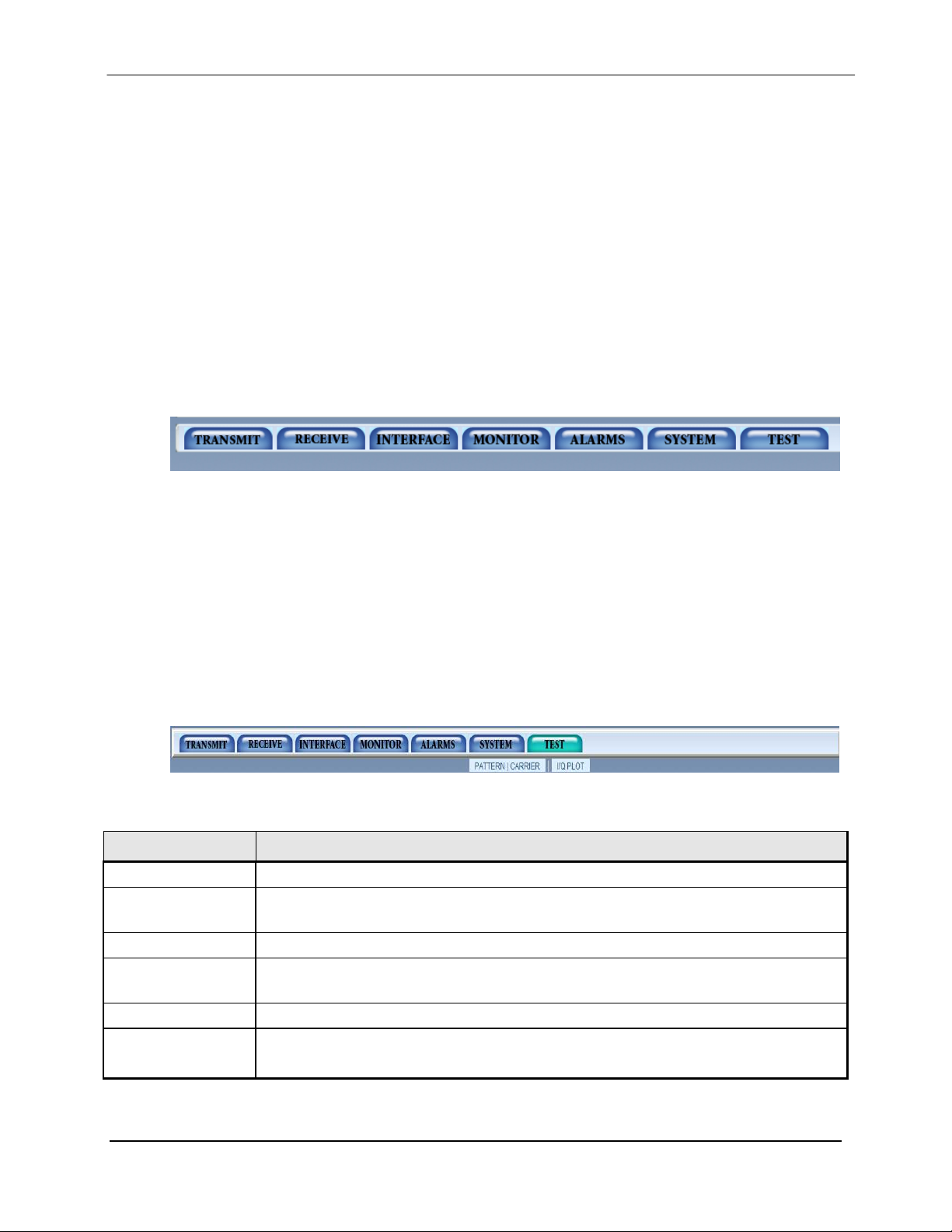
DMD1050 Satellite Modem Board Web Browser
Product Name
This shows which product is con nected to the interface.
Name/Location
Alarm and Monitor
This shows fault and performance status.
drop-down menu opens.
Data Entry Area
Edit parameters in this area.
Contact Information
Select Contact Us to email Customer Service.
7.2.1 Appearance
This site is a monitor and control of an individual complete satellite terminal. With a front panel
look and feel, and an appearance that resembles the DMD20 layout, the product features a
familiar look.
7.2.2 Navigation
The navigation scheme consists of gel tabs that correspond to the front panel top-level menu
selections. When the mouse is dragged over a tab, it gets highlighted with a rollov er ef f ect and a
sub-level of selections is revealed. These typically correspond to the front panel sub-menus, but
some areas have been combined.
Below the navigation menus, a content page will show the current control scope. This will be the
last user selected control page. At the top of the page, breadcrumb links remind the user how the
page is selected.
The menu works as follows:
Mousing over a global navigation link causes the corresponding subglobal division to be
revealed and all other sub global divisions to be hidden.
Mousing off a sub global menu link (outside a specified region x and y pixels from the top of
the page), causes all sub global divisions to be hidden.
The position of the mouse is continuously being monitored.
Thus, we have a show-hide layer submenu effect.
Table 7-1
Description Function
Product
This shows the name and location of t he unit.
Menu Tabs The menu tabs give you access to data and control entry. Move the cursor to a tab and a
Product Information
MN-DMD1050 7–2
Revision 9
This gives you access to technical trouble-shooting, product options and specifications.
Page 97

DMD1050 Satellite Modem Board Web Browser
Power
Green
Indicates that the unit is turned on.
Fault
Red
Indicates a hardware fault for the unit .
in the Terminal Mode.
FTP.
Transmit On
Green
Indicates that the Modulator tr ansmitter is on.
Major Alarm
Red
Indicates that the Transmit Dir ection has failed, losing traffi c .
Minor Alarm
Yellow
Indicates that a Transmit Warning Condition exists.
activity.
including FEC Sync.
Major Alarm
Red
Indicates that the Receive Dir ec tion has failed, losing traffic.
Minor Alarm
Yellow
Indicates that a Receive Warni ng Condition exists.
activity.
7.2.3 LED Indicators
Twelve LEDs on the DMD1050 GUI Interface (R efer to Table 7-2) indicate the status of the
DMD1050’s operation. The LED colors maintain a consistent meaning. Green is appropriate for
normal operation, Yellow means that there is a condition not proper for normal operation, and
Red indicates a fault condition that will result in lost communications.
Table 7-2.
LED Color Function
Modem LED Indicators
Event Yellow Indicates that a con dit ion or event has occurred that t he modem
has stored in memory. The events may be viewed from the GUI or
Remote Green Indicates that the unit is in the process of updating firmware with
Modulator LED Indicators
Test Mode Yellow Indicates th at the transmitter is involved in a curr ent Test Mode
Demodulator LED Indicators
Signal Lock Green Indicates that the receiv er locked to an incoming carrier and data,
Test Mode Yellow Indicates th at the receiver is involved in a current T est Mode
MN-DMD1050 7–3
Revision 9
Page 98

DMD1050 Satellite Modem Board Web Browser
7.3 GUI Screen Menus
There are four main menus displayed on the Introduction screen upon startup of the web browser.
This screen will give a brief overview of the product and contains no configurable items. The
four main menus and with submenus are:
Introduction
Password Setup
o Access
o Preferences
IP Administration
o Modem Addressing
o Configure Apps
o Configure PC
Monitor and Control
o Transmit
o Receive
o Interface
o Monitor
o Alarms
o System
o Test
MN-DMD1050 7–4
Revision 9
Page 99

DMD1050 Satellite Modem Board Web Browser
7.3.1 Introduction Menu
This menu will first appear when starting up the web browser. This page lists the general f eatures
of the unit, and lists a brief description of the unit. Notice on the bottom of the page that there are
selections for Technical Specifications, Product Options, Troubleshooting, About Us, and Contact
us. Access these areas for further detailed description of the selection.
Figure 7.2. Introduction Screen
MN-DMD1050 7–5
Revision 9
Page 100

DMD1050 Satellite Modem Board Web Browser
7.3.1.1 Login Screen
Upon initially accessing the Password Setup, IP Administration and Monitor & Control
configuration menu tabs a login prompt will appear. In order to gain access to any of the
configuration menus, log in with the correct user name and password. (The factory default login
name is “admin” and the default password is “admin”). For further information on setting user
profiles see Section 7.2.3 IP and Application Administration Menu
.
Figure 7-3. Login Screen
MN-DMD1050 7–6
Revision 9
 Loading...